Monteringsanvisning - Handicare
Monteringsanvisning - Handicare
Monteringsanvisning - Handicare

Create successful ePaper yourself
Turn your PDF publications into a flip-book with our unique Google optimized e-Paper software.
INNHOLD<br />
Monteringsveiledning<br />
Vimec V64/V74<br />
Plattform trappeheis<br />
1. Levering ..............................................................................................................side 2<br />
2. Montering av skinnen ........................................................................................side 3<br />
3. Montering av drivvogn ......................................................................................side 4<br />
4. Komplett aktuator montering ...........................................................................side 4<br />
5. Montering av drivenhet .....................................................................................side 4<br />
6. Montering av plattform med motorisert sidepåkjøring ...................................side 7<br />
7. Montering av plattform .....................................................................................side 9<br />
8. Elektrisk tilkobling ..............................................................................................side 10<br />
9. Kontroll av montering ........................................................................................side 10<br />
10. Montering av deksler drivenhet ........................................................................side 10<br />
11. Sluttkontroll ........................................................................................................side 11
2<br />
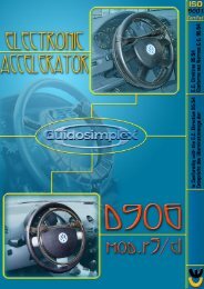
Innhold ved levering<br />
1) INNHOLD VED LEVERING<br />
Trappeheisen 1) SYSTEM SUPPLY leveres delt CONDITION i følgende komponenter:<br />
The stairlift is supplied subdivided into the following<br />
Drivenhet components: (fi g 1/a)<br />
Komplett med girmotor, sikkerhetsbøyler, drivverks-<br />
Lift structure (Fig. 1/a)<br />
og elektriske komponenter.<br />
Complete with gear motor, safety bars, drive<br />
components and electrical system.<br />
Plattform (fi g 1/b)<br />
Komplett Carrier platform med deksler (Fig. og 1/b) sikkerhetsbrett (inkl. mikrobrytere).<br />
Complete with guard boards and sensor base with<br />
safety microswitches.<br />
Drivvogn (fi g 2)<br />
Komplett Drive carriage med fangapparat (Fig. 2) – fi g 2/a.<br />
Complete with safety gear - Fig. 2/a.<br />
Betjeningspanel på heis(fi g 3/a)<br />
Lift control board (Fig. 3/a)<br />
Med 2, 4 eller 6 knapper.<br />
With 2 - 4 or 6 buttons.<br />
(Heis<br />
(lift up/down).<br />
opp/ned).<br />
(Plattform (platform heve/senke).<br />
fold/lower).<br />
(Bøyler (bars open/close). åpne/lukke).<br />
Betjeningspanel Control board at ved floor gulv (Fig. (fi 3/b) g 3/b)<br />
Med With 4 4 knapper buttons (B.C.).<br />
Med With 6 6 knapper buttons (B.I. – - B.R.).<br />
Rail unit (Fig. 4)<br />
Skinne (fi g 4) Består av:<br />
Comprising:<br />
- komplett skinne produsert etter mål (fi g 4/a)<br />
- Complete rail constructed to measure (Fig. 4/a).<br />
-<br />
-<br />
kjede<br />
Chain<br />
løpebane<br />
runway (Fig.<br />
(fi g<br />
4/a).<br />
4/a)<br />
- - kjede Cable til carrier kabelholder chain and og electric elektriske wires kabler (Fig. 4/c).<br />
- - føtter Feet for til trapper stairs (Fig. (fi g 4/d) 4/d) (optional). (valgfri)<br />
FIG.3 b<br />
FIG.4<br />
b<br />
a<br />
c<br />
FIG.1<br />
FIG.2<br />
a<br />
a<br />
d<br />
b<br />
a<br />
d<br />
b<br />
b
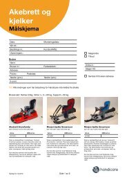
2. MONTERING AV SKINNEN<br />
2) INSTALLING THE RAIL<br />
Installasjons<br />
ONLY FOR STOCK<br />
tips!<br />
GUIDE:<br />
Følg - Following dimensjonene the som dimensions vist på monterings shown tegningen on the<br />
(eksempel assembly fi drawing g 6) , som (see er example spesifi kk in til Fig. hver 6) enkelt specific installasjon,<br />
to each installation, plasser skinnen place i riktig the posisjon rail in position på skinne- of<br />
fotens the guide brakett connections med skruer using M8x25 the (fi screws g 5/a) (moment: M8 x 25<br />
1,6 (Fig. – 2 5/a) Nm) (driving torque: 1,6 ÷ 2 DaNm).<br />
- If the guide junction is projected, connect to plates<br />
Hvis (plates skinnen + dowels kommer with driving i to eller torque: fl ere 5 deler ÷ 6 DaNm monter - Fig.<br />
disse 1/b). sammen med skjøtestykkene og medfølgende<br />
skruer - If the som system vist på installation fi g. 5b. drawing envisages then,<br />
Hvis place skinnen the feet er levert (optional) med as føtter, shown plasser in Fig. føttene 6/a, fixed<br />
(valgfritt) resting on som the vist floor u or fi g on 6/a, the stairs. fast montert på gulvet<br />
eller - When trappen. mounting a rail without stair steps, supported<br />
Hvis by the montering wall-mountings uten trappeføtter, only, use the men positioning med veggfes- feet<br />
ter, provided bruk eventuelt (accessories posisjoneringsføtter. for the installation (tilbehør technician). for<br />
montør). - After fixing all the feet (if present) and checking the<br />
Etter project montering dimensions av alle (Fig. føttene, 8) prearrange eventuelt veggfes- the wall<br />
tene, attachments kontroller (shim prosjektdimensjonene with washers to reach som the vist minimum på (fi g<br />
8), dimension sjekk at avstanden 100 mm) mellom and fixed vegg by og inserting forkant skinne the<br />
er expansion minimum plugs 100mm provided +/- 0,5mm. (Fig. 7). (bruk mellomleggsskiver<br />
N.B.: for maximum å oppnå flatness riktig dimensjonen, error on 4 connecting se fi g 7). points<br />
of 1 mm.<br />
FIG.7<br />
FIG.8<br />
Koblingsblokk<br />
C<br />
CONNECTOR<br />
BLOCK<br />
CONTROL<br />
BOARD<br />
HIGH LEVEL<br />
SHEATH<br />
Ø 20<br />
100<br />
Kontrollbrett<br />
øvre nivå<br />
Mantel<br />
Ø20mm<br />
A<br />
Max.1 mm<br />
FIG.5<br />
MAX. 500 MAX. 1200 MAX. 300<br />
FIG.6<br />
a<br />
a A (V64) A (V74) B C<br />
10 ÷ 12<br />
12,1 ÷ 14<br />
14,1 ÷ 16<br />
16,1 ÷ 18<br />
18,1 ÷ 20<br />
20,1 ÷ 22<br />
22,1 ÷ 24<br />
24,1 ÷ 26<br />
26,1 ÷ 28<br />
28,1 ÷ 30<br />
30,1 ÷ 32<br />
32,1 ÷ 34<br />
34,1 ÷ 36<br />
36,1 ÷ 38<br />
38,1 ÷ 40<br />
40,1 ÷ 42<br />
42,1 ÷ 44<br />
44,1 ÷ 46<br />
46,1 ÷ 48<br />
48,1 ÷ 50<br />
Montering av skinnen<br />
a<br />
a<br />
163<br />
127<br />
110<br />
100<br />
84<br />
64<br />
46<br />
43<br />
50<br />
56<br />
63<br />
69<br />
76<br />
83<br />
90<br />
97<br />
104<br />
112<br />
120<br />
129<br />
± 0,25<br />
377,5<br />
MAX. 1200<br />
263<br />
227<br />
210<br />
200<br />
184<br />
164<br />
146<br />
143<br />
150<br />
156<br />
163<br />
169<br />
176<br />
183<br />
190<br />
197<br />
204<br />
212<br />
220<br />
229<br />
SHEATH<br />
Ø 20<br />
CONTROL<br />
BOARD<br />
LOW LEVEL<br />
B<br />
MIN. 200<br />
169<br />
156<br />
144<br />
133<br />
122<br />
113<br />
103<br />
92<br />
85<br />
74<br />
68<br />
61<br />
54<br />
48<br />
42<br />
37<br />
33<br />
29<br />
25<br />
22<br />
Mantel<br />
Ø20mm<br />
Kontrollbrett<br />
nedre nivå<br />
b<br />
a<br />
304<br />
320<br />
336<br />
351<br />
368<br />
384<br />
400<br />
417<br />
433<br />
450<br />
467<br />
483<br />
500<br />
517<br />
533<br />
550<br />
566<br />
583<br />
600<br />
615<br />
b<br />
3
4<br />
Montering av skinnen<br />
Monterings tips!<br />
ONLY FOR STOCK GUIDE:<br />
- Holding to the specific dimensions (Fig. 9) for each equipment, proceed to the drilling of the chain<br />
Ihht til de spesifi kke dimensjonene for hver enkelt enhet (fi g 9), borr nå hullene i kjedeholderprofi len som vist<br />
holder profile (aluminium bonnet - Fig. 10).<br />
på - fi g Assemble 10 (aluminiumsdekselt).<br />
the terminal mesh (Fig. 11/a) to the cable carriage chain (Fig. 11/b) and fix it to the support.<br />
Monter The cable strekkavlasteren (Fig. 11/c) must (fi g 11a) be placed med kabelkjedet with the protection (fi g 11/b) guard og fest (plus det its til holderen. seal - Fig. Kabelen 11/d) bending (fi g 11c) the festes two<br />
med tongues beskyttelsesdeksel (Fig. 11/e). og tetningen (fi g 11d), ved å bøye ut de to leppene (fi g 11c).<br />
Fest - Insert kabelkjeden the cable (fi g carriage 9a) med chain skrue (Fig. TSPCE 9/a) M4x45, and fix skiver it with 6x18 the og indicated låsemutter screw M4. TSPCE Fest kabelklemmen M4x45, washer (fi 6x18 g 9b)<br />
med and vist self-locking skrue TE M6x14 nut M4. og låsemutter Fix the cable-stopper M6. clamp (Fig. 9/b) with the indicated screw TE M6x14 and<br />
Monter self-locking og fest teleskop-platen nut M6. (fi g 9f) med selvgjengene skruer 4,8x13 (fi g 9g).<br />
Monter - Assemble og fest and kabelholderprofi fix the telescoping len. plate (Fig. 9/f) with self-tapping screws 4.8x13 (Fig. 9/g).<br />
Monter - Assemble beskyttelsesdekselet and fix the cable med guide viste profile. selvgjengene skruer 4,8x13 på skinnens nedre del (fi g 9d).<br />
- Assemble the guard and the cover with the indicated self-threading screws 4.8x13, on the guide lower<br />
side (Fig. 9/d).<br />
FIG.9<br />
Nedre<br />
LOW SIDE<br />
d<br />
FIG.10 FIG.11<br />
SECTION A-A SECTION B-B<br />
Ø 5<br />
g<br />
Ø 10<br />
f<br />
15<br />
A<br />
Ø 7<br />
c<br />
g<br />
a<br />
40<br />
A<br />
A<br />
a<br />
c<br />
g<br />
b<br />
HIGH SIDE<br />
Guide lenght Dimension A<br />
from 1500 to 3300<br />
from 3300 to 6900<br />
from 6900 to 14100<br />
a<br />
Øvre<br />
b<br />
c d<br />
e<br />
g<br />
50<br />
B<br />
B<br />
1400<br />
3200<br />
6800<br />
e
Monterings tips!<br />
Legg ONLY tilførselskabelen FOR STOCK GUIDE: inne i spiralhylsa og fest med<br />
korrekt - Pass kabel the power gjennomføring supply cable til øvre inside skinnedeksel the spiral<br />
(fi tube g 9e). and fix with the proper fairlead to the guard<br />
Fest in plate kabelkjedeholderen cover support ved at high å borre side Ø (Fig. 4,25 9/e). hull, i<br />
skinnebraketten - Drill with Ø 4,25 og fest the chain med korrekt carriage selvgjengene<br />
profile close<br />
skruer to the 4,8x13 guide (fi connection g 9c). and fix with the proper<br />
self-threading screws 4,8x13 (Fig. 9/c).<br />
3) MONTERING AV DRIVVOGN<br />
Ta 3) med INSTALLING drivvognen THE til CARRIAGE øvre nivå, fjern deretter den<br />
mekaniske - Bring the endestopperen carriage unit to the på upper enden floor av skinnen. then remove<br />
Monter the mechanical drivvognen limit på stop skinnen buffer on the top end of the<br />
Monter rail. kabelkjedets brakett til drivvognen (mot retning<br />
- Assemble nedover) the med cover medfølgende and the plate skruer with (fi the g 12c). proper<br />
Kontroller self-threading nå at screws fangapparatest 4,8x13, on krok the guide er horisontal at high side. (fi g<br />
12e) og at pinnene (fi g 12a) er vertikalt innstilt (bruk<br />
- Fix the cable carriage plate to the carriage (facing in<br />
vater).<br />
the down direction) using suitable screws (Fig. 12/c).<br />
NB: Hvert enkelt anlegg er påført ett kort som<br />
forteller - At this om point, innstilling check that av fangapparatet.<br />
the safety gear hook is<br />
Koble horizontal fra fangapparatets (Fig. 12/e) and krok that the for pins å unngå (Fig. aktivering 12/a - Fig.<br />
mens<br />
12/b)<br />
heisen<br />
are vertically<br />
monteres.<br />
aligned (using a spirit level).<br />
N.B.: Each system will carry a card listing the<br />
4) operations MONTERING to be AV carried AKTUATOR out. FOR MOTORISERT<br />
PLATTFORM - Engage the safety gear hook to prevent undesirable<br />
Monter movements aktuatoren when the (fi g lift 13a) structure med mutter is fitted. (fi g 13b) og<br />
skive (fi g 13c) til plattformutløseren (13d). Husk å<br />
montere 4) COMPLETE plattformutløseren ACTUATOR riktig ASSEMBLY vei avhengig av om<br />
aktatoren 1) Assemble monteres the actuator på høyre (Fig. eller 13/a) venstre with nut side. (Fig. Sjekk 13/<br />
aktatordimmensjonen b), washer (Fig. 13/c) ihht and til friction fi g 13. (Fig. 13/d) paying<br />
Fest attention gaffelen that på the aktuatoren release friction ved hjelp must av result gummidem- opposite<br />
pere, to the skiver, machine skrue and og check låsemutter the quote som 271 vist mm på (vedi fi g 14 Fig.<br />
a-e.<br />
13) when the actuator is closed (therefore on the opposite<br />
side of the micros of the actuator itself).<br />
MERK: 2) On Skru the support gummidemperne (fork) insert the passe two inntill. rubber pieces<br />
(vibration-damping) (Fig. 14/b), then screw the actua-<br />
Fest tor (Fig. aktuatorens 14/e) with gaffel a TE til M10x90 drivenheten screw (Fig. med 14/a), skrue a Ø<br />
M10x30<br />
UNI 6593<br />
skruer<br />
washer<br />
se fi<br />
(Fig.<br />
g 15.<br />
14/c) and M10 self-locking nut<br />
(Fig. 14/d) (it is advisable doing this before as the frame<br />
Aktiviser plattformens nødutløser (fi g 16a).<br />
is obstructing the field).<br />
Trekk<br />
Please<br />
utløserrøret<br />
Note: screw<br />
ned<br />
till<br />
og<br />
placing<br />
fest det<br />
the<br />
til plattform<br />
rubber spacers<br />
braketten<br />
at support M8x50 skrue level. (Fig 17) husk å bruke låsevæske.<br />
3) Screw into the frame (on the machine low side) (Fig.<br />
5) MONTERING AV DRIVENHET TIL DRIVVOGN<br />
15/c) with M10x30 screw (Fig. 15/a) and Ø 10 washer<br />
Sentrer drivenhet og drivvogn.<br />
(Fig. 15/b).<br />
Koble til kablene fra kabelkjedet :<br />
(blå 4) Release kabel 4x1 the til friction strømforsyning) (Fig. 16/a).<br />
(grønn 5) Bring kabel the friction 8x0,35 tube til betjeningspanel)(valgfri)<br />
(Fig. 17/a) at the same level<br />
as the support holes (Fig. 17/b) and fix with TE M8x50<br />
screw (Fig. 17/c) and thread-locking adhesive.<br />
5) FITTING THE LIFT BODYWORK<br />
- Bring the lift bodywork towards the carriage, trying to<br />
align it with the carriage sprocket.<br />
- Connect the connectors of the cable carrier chain<br />
driver:<br />
(blue cable 4 x 1 for power supply)<br />
(green cable 8 x 0,35 for control board) (optional)<br />
FIG.12<br />
FIG.13<br />
FIG.14<br />
e<br />
b<br />
f<br />
d<br />
e<br />
274 0<br />
-0,5<br />
c<br />
b<br />
b<br />
c<br />
d<br />
h<br />
a<br />
a<br />
b<br />
Montering<br />
c<br />
a<br />
d<br />
c<br />
g<br />
5
6<br />
Montering<br />
Fest den nedre endebryter (SQ16 eller SQ12)(fi g 12g).<br />
Fest - Fix den the øvre down endebryter limit stop plate (SQ16 (SQ16 eller or SQ12) (Fig. og øvre 12/g).<br />
sikkerhetsbryter - Fix the up limit (fi stop g 12h). plate (SQ16 or SQ12) and the up<br />
Fest overlimits drivenheten microswitch til drivvognen (SQ4) (Fig. med 12/h). tre skruer (fi g<br />
12d), - Connect drivenheten the safety skal gear være microswitch horisontalt. connector Moment (SQ2) -<br />
M10x1 Fig. 12/f. – 3,5 Nm.<br />
Bor - Fix ett the hull lift (min body Ø10mm, to the carriage dybde 4mm) by means gjennom of the 3<br />
M12 screws hullet - Fig. (fi g 12/d, 18a) checking på drivenheten. that it is Skru horizontal. deretter<br />
inn (Tightening M12x25 settskruen torque M10x1 inn - i hullet 3.5 DaNm). og fest den med<br />
vedlagte - Use a mutter. bit with diameter 10 mm to drill a hole at least<br />
Fest 4 mm drivkjedet deep in (fi the g carriage 18b) med plate vedlagte through kjedelås, the M12 og hole<br />
juster (Fig. med 18/a) kjedestrammeren on the frame. Then (forhåndsmontert screw the M12x25 på stud-<br />
undersiden bolt supplied av into vognen)(fi the hole g and 18c). fix it with the nut provided.<br />
- Fit the drive chain (Fig. 18/b) with links as supplied<br />
NB and – ikke adjust stram using opp the kjeden chain stretcher for mye! (Fig. 18/c), premounted<br />
on the underside of the carriage.<br />
Hvis N.B.: nødvendig, Do not over-stretch bruk nødsveiven the chain. til manuell drift for<br />
å - forenkle If necessary, montering use the av handwheel kjedestrammeren for manual (fi g opera- 19a).<br />
Fjern tion støttebena to adjust the og chain håndtak in order fra to drivenheten. simplify fitting of the<br />
chain stretcher - Fig. 19/a.<br />
- Remove the supporting feet and handles from the lift<br />
body.<br />
FIG.15<br />
FIG.16<br />
a<br />
a<br />
b<br />
c<br />
FIG.17<br />
FIG.18<br />
FIG.19<br />
b<br />
c<br />
b<br />
a<br />
a<br />
c<br />
a
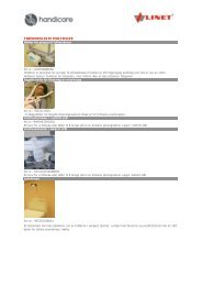
6) MONTERING AV PLATTFORMEN MED MOTORISERT<br />
SIDEPÅKJØRING 6) ASSEMBLING (B.I. – B.C. THE – B.R.) PLATFORM WITH<br />
Motorisert MOTORIZED sidepåkjøring ACCESS er FRONTAL tilgjengelig (B.I. som - B.C. tilbehør. - B.R.)<br />
(fi On g 20a). customer Dette request tilbehøret it is tillater, possible kun to have på nederste a footboard<br />
nivå, with adkomst/utgang overturning front vinkelrett side (Fig. 20/a). på plattformen.<br />
Such a footboard permits, on the lower floor only, to<br />
6.1) MONTERING AV MOTORISERT SIDEPÅKJØRING<br />
access/go down perpendicularly to the machine.<br />
a) Demonter plattformgulvet fra plattform ved å skru<br />
6.1) ut gjeldende Assembling skruer. the platform<br />
b) a) Påse Remove at monteringsbrakettene the top plate from the på platform drivenheten by undoing er i<br />
the korrekt relative monteringsposisjon screws. (fi g 21a/b). Fjern kilen<br />
og plaststripset.<br />
b) Make sure that the two platform supports, fixed by a<br />
c) Sett på plass plattformen, hold den vertikalt og<br />
wedge and a plastic clamp, are in the assembly position<br />
sving den 90° nedover som vist (fi g 22).<br />
(Fig. 21/a/b).<br />
d) Fest plattformen til drivenheten med M8 skruer<br />
c) (fi g Fit 22a). the platform, keeping it vertical and turning it<br />
e) through Fest sikkerhetsbrettets 90° as shown in to (Fig. mikrobrytere 22). (fi g 23a)<br />
til plattformen – før de mellom sikkerhetsbrettet og<br />
d) Fix the platform to the frame using the relative M8<br />
flathead<br />
plattformrammen<br />
screws (Fig.<br />
(fi g<br />
22/a).<br />
23b).<br />
Hvis e) Fix nødvendig the two microswitches kan sikkerhetsbrettets of the sensor utløserarm base (Fig. (fi g<br />
23/c) 23/a) skyves to the platform, tilbake for passing å gi plass them til between gjennomføring the sensor<br />
av base mikrobryterne. and the platform Gjenopprett frame (Fig. deretter 23/b). original<br />
posisjon If necessary, slik at back sikkerhetsbrettet off the sensor utløser base mikro- tripping cams<br />
bryterne (Fig. 23/c) når to den allow skyves the microswitch ned. to pass.<br />
Then restore the original positions so that the sensor<br />
base trips the microswitches when it is pressed.<br />
FIG.20<br />
a<br />
FIG.21<br />
FIG.22<br />
a<br />
FIG.23<br />
c<br />
b<br />
a<br />
b<br />
Montering<br />
d<br />
a<br />
a<br />
c<br />
7
8<br />
Montering<br />
f) Koble til av-/påkjøringsklaffenes kontrollkabler (fi g<br />
24f-e) f) Connect til gaffelleddet the lateral (fi guard g 24b). board operating cables<br />
(Fig. 24/f) and frontal (Fig. 24/e) to the fork (Fig. 24/b).<br />
Trekk - Tighten til med with mutter nut and og screw. låseskrue.<br />
Monter eksenter (fi g 24h) med ledeblekk (fi g 24g), på<br />
- Insert the eccentric (Fig. 24/h) with handling belt (Fig.<br />
spesialtappen (fi g 24i) og fest med låsering (fi g 24m).<br />
24/g), front chute on the special pin (Fig. 24/i) and<br />
block with seeger (Fig. 24/m).<br />
FIG.24<br />
i<br />
b<br />
h<br />
e<br />
c e<br />
Fortsett Proceeds med to å check kontrollere the proper at påkjøringsklaffene working of the front funacgerercess tilfredstillende.<br />
chute:<br />
Kontroller - Check the at vinkelen angle between mellom the plattformgulvet chute (in working (i posi-<br />
arbeidsstilling) tion) and the footboard og påkjøringsklaffen is 90° (Fig. 25). er minimum 90°<br />
max.<br />
- Check<br />
120o<br />
the<br />
(fi g<br />
front<br />
25).<br />
access micro chute intervenes with a<br />
Hvis maximum påkjøringsklaffene rotation of 30° ikke of åpner the same eller chute lukker with korrerekt,spect juster to the til working spesifi sert position posisjon as in med Fig. gaffelen 25. (fi g<br />
24b).<br />
- If the guards are not opened or closed correctly, adjust<br />
to the specified position using the register fork (Fig.21/<br />
b).<br />
f<br />
m<br />
g<br />
FIG.25 FIG.26<br />
B.R.: fest kabelen (fi g 24f) til påkjøringsbrettet med<br />
spesialskruer.<br />
B.R.: fix the cable (Fig. 24/f) already present on the<br />
Fest side kabeløyet bar chute (fi with g 24e) special til eksenteren screws. (fi g 24h) med<br />
skrue, - Fix the mutter cable og eye låsemutter, (Fig. 24/e) med to the tilstrekkelig eccentric (Fig. klaring 24/<br />
for h) rotasjon by screw, av selve nut and kabeløyet. lock nut leaving the necessary<br />
clearance for the rotation of the eye itself.<br />
125<br />
b<br />
a<br />
g) g) Monter Replace plattformgulvet.<br />
the top plate on the platform using the rela-<br />
h) tive Fjern fixing kilen screws. og plastklemmen (fi g 21c-d).<br />
i) Trekk til justeringsskruen og låsemutteren med 4<br />
h) Remove the wedge and the plastic clamp (Fig. 21/<br />
Nm (fi g 26a-c).<br />
c/d) used to keep the platform horizontal during the<br />
adjustments from the platform supports.<br />
I) Kontroller at plattformens nødutløser blir resatt.<br />
i) Tighten with a driving torque of 4 daN ± 0,1the dowel,<br />
the nut and the locknut (Fig. 26/a,b,c).<br />
d<br />
l) Check friction group is engaged.<br />
c<br />
b<br />
a
7) MONTERING AV PLATTFORMEN<br />
MED 7) ASSEMBLING STANDARD PÅKJØRING THE PLATFORM<br />
a) Remove the top plate from the platform by undoing<br />
a) the Demonter relative plattformgulvet screws. fra plattform ved å skru<br />
ut gjeldende skruer.<br />
b) b) Påse Make at monteringsbrakettene sure that the two platform på supports, drivenheten fixed er by i a<br />
wedge korrekt and monteringsposisjon a plastic clamp, are (fi in g the 27a/b). assembly Fjern position kilen<br />
(Fig. og plaststripset.<br />
27/a/b).<br />
c) Sett på plass plattformen, hold den vertikalt og<br />
c)<br />
sving<br />
Fit the<br />
den<br />
platform,<br />
90° nedover<br />
keeping<br />
som<br />
it<br />
vist<br />
vertical<br />
(fi g 28).<br />
and turning it<br />
through 90° as shown in (Fig. 28).<br />
d) Fest plattformen til drivenheten med M8 skruer<br />
d)<br />
(fi g<br />
Fix<br />
28a).<br />
the platform to the frame using the relative M8<br />
e) flathead Fest sikkerhetsbrettets screws (Fig. 28/a). to mikrobrytere (fi g 29a)<br />
til plattformen – før de mellom sikkerhetsbrettet og<br />
e) plattformrammen Fix the two microswitches (fi g 29b). of the sensor base (Fig.<br />
29/a) to the platform, passing them between the sensor<br />
Hvis base nødvendig and the platform kan sikkerhetsbrettets frame (Fig. 29/b). utløserarm (fi g<br />
29/c) If necessary, skyves tilbake back off for the å gi sensor plass til base gjennomføring<br />
tripping cams<br />
av (Fig. mikrobryterne. 29/c) to allow Gjenopprett the microswitch deretter to pass. original posisjon<br />
Then<br />
slik<br />
restore<br />
at sikkerhetsbrettet<br />
the original positions<br />
utløser<br />
so<br />
mikrobryterne<br />
that the sensor<br />
base trips the microswitches when it is pressed.<br />
når den skyves ned.<br />
f) Connect the lateral guard board operating cables to<br />
f) the Koble relative til av-/påkjøringsklaffenes bar actuators, passing them kontrollkabler around the til pin<br />
(Fig.30/a). gaffelleddet (fi g 30)ved å føre dem rundt pinnen<br />
If (fi the g 30a). guards are not opened or closed correctly, adjust<br />
to the specified position using the register fork (Fig.30/<br />
g) b). Monter plattformgulvet.<br />
h) Fjern kilen og plastklemmen (fi g 21c-d).<br />
g) Replace the top plate on the platform using the rela-<br />
i)<br />
tive<br />
Trekk<br />
fixing<br />
til justeringsskruen<br />
screws.<br />
og låsemutteren med 4<br />
Nm (fi g 26a-c).<br />
h) Remove the wedge and the plastic clamp (Fig. 27/<br />
I) c/d) Kontroller used to at keep plattformens the platform nødutløser horizontal blir during resatt. the<br />
adjustments from the platform supports.<br />
i) Tighten with a driving torque of 4 daN ± 0,1the dowel,<br />
the nut and the locknut (Fig. 29/d,e,f).<br />
l) Check friction group is engaged.<br />
FIG.29<br />
a<br />
b<br />
c<br />
FIG.27<br />
FIG.28<br />
a<br />
c<br />
b<br />
f<br />
Montering<br />
d<br />
e d<br />
a<br />
9
10<br />
Elektrisk tilkobling<br />
8) ELEKTRISK TILKOBLING<br />
8) CONNECTING THE ELECTRICAL SYSTEM<br />
To Two kabler wires kommer lead out ut from av av the toppen top end på of den the ekstruderte extruded<br />
aluminiumskanalen aluminium raceway på on skinnen the rail (Fig. (fi g 31a-b). 31/a/b)<br />
1. - kabel blue wire 4x1, 4x1, strømforsyning<br />
power supply<br />
2. - kabel green 8x0,35 wire 8x0,35 til betjeningspanel for control board (valgfri) at floor (optional)<br />
Koble Connect til kablene these wires som as følger: follows:<br />
Koble - Connect 4x1 kabelen the 4x1 (fi blue g 31a) wire til (Fig. nettforsyningens 31/a) to the power sikring<br />
supply (installert mains av using kunde the på circuit forhånd). breaker installed<br />
Koble<br />
previously<br />
8x0,35<br />
by<br />
kabelen<br />
the customer<br />
til koblingsboksen<br />
(fairlead + sheath).<br />
under skin-<br />
- If the optional floor control board is present:<br />
nens lokk ved det øvre nivå (fi g 31b).<br />
- Connect the 8x0,35 green wire to the junction box<br />
I boksen,<br />
under<br />
koble<br />
the lid<br />
sammen<br />
of the rail<br />
de<br />
at<br />
to<br />
the<br />
kablene<br />
top end<br />
for<br />
(Fig.<br />
hente/<br />
31/b).<br />
sendetablåene - In the box, som connect vist i vedlagte the two cables skjema. provided for<br />
Koble the til floor det øvre push-buttons hente/sendetablåets as shown in kabel the enclosed direkte,<br />
pass diagram. på å beskytte den hele veien, ved hjelp av kanalen.<br />
- Connect the top control board cable (Fig. 31/c)<br />
Legg directly, kabelen taking for nedre care to hente/sendetablå protect it throughout (fi g its 31d) path<br />
gjennom using den the nedre raceway skinnen provided. og ut nederst, koble den<br />
deretter - Pass til nedre the cable hente/sendetablå, of the control board pass for på the å be- lower<br />
skytte<br />
floor<br />
den<br />
(Fig.<br />
hele<br />
31/d)<br />
veien,<br />
through<br />
ved hjelp<br />
the<br />
av<br />
lower<br />
den medfølgende<br />
tubular rail,<br />
leading it out at the bottom end, then connect it to<br />
plastkanalen.<br />
the lower floor control board, taking care to protect<br />
Monter<br />
it throughout<br />
de to endedekslene<br />
its path using<br />
på<br />
the<br />
skinnen.<br />
raceway provided.<br />
- Fit the two rail cover guards (Fig. 32).<br />
NB: Sikringen til hovedstrømforsyningen må være<br />
N.B.: The differential security breaker connected to the<br />
installert av kunden før heisen kan monteres.<br />
mains power supply must be installed by the customer<br />
before the system is installed.<br />
9) KONTROLL AV KJØRERETNING<br />
Kontoller 9) INSTALLATION at driftsmodusbryteren CHECKS (JB22 – JB23) er satt<br />
ihht - Check systemtype that the (RH operating eller LH). mode setting switch (JB22 -<br />
Kontroller JB23) is set mot as vedlagte appropriate koblingsskjema to the system at type alle (RH hei- or<br />
sens LH). mikrobrytere er posisjonert korrekt.<br />
- Check that all the lift’s microswitches are correctly<br />
positioned,consulting the electrical system diagrams<br />
10)<br />
provided.<br />
MONTERING AV DEKSLER<br />
Monter 10) FITTING alle deksler THE BODYWORK på drivenhet og SECTIONS drivvogn som<br />
fulgte - Fit all med the heisen. bodywork sections provided with the lift.<br />
FIG.30<br />
b 125<br />
FIG.31<br />
c<br />
d<br />
FIG.32<br />
b<br />
a<br />
a
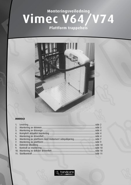
11) SLUTTKONTROLL<br />
11) FINAL TESTING<br />
Koble til hovedstrømmen og utfør følgende<br />
funksjonstester:<br />
Supply power to the system and perform the<br />
following functional checks:<br />
Belastningsprøve<br />
- Load test:<br />
Last heisen med 1,1 ganger maks belastning påført<br />
- Load the lift with 1.1 times the rated load stated on<br />
merkeplaten.<br />
the nameplate.<br />
Kjør heisen opp og ned fl ere ganger, og kontroller<br />
heisens - Send the stabilitet lift up and på skinnen. down several times, checking its<br />
Kjør stability heisen on til the øvre rail. nivå og plasser plattformen i normal<br />
endepossisjon for avkjøring. Påse at mikrobryte-<br />
- Drive the machine to the upper level and place the<br />
ren platform skyves as inn to (fi let g the 33a). unloading of the bodywork and<br />
Kjør assemble heisen the til nedre cam on nivå the og guide plasser (Fig. plattformen 33/a), so that i the<br />
normal rise limitstop endepossisjon micro is pressed for avkjøring. on (Fig. Påse 33/b). at mikrobryteren<br />
skyves inn (fi g 33d).<br />
- Drive the machine to the lower level and place the<br />
Gjenta operasjonen for å kontrollere endepossisjon<br />
platform as to let the unloading of the bodywork and<br />
Lås assemble anslaget the til cam endebryterne on the guide med (Fig. den 33/c),so sylindriske that the<br />
pinnen descent Ø4x30. limitstop micro operates (Fig. 33/d).<br />
Plasser det tredje anslaget (mekanisk ekstra stem-<br />
- Repeat the operation to check the operating of the<br />
pelslag) med sylindrisk pinne Ø4x30, til skinnens<br />
limit stop and extra stroke micro, making the machine<br />
nedstigningsside<br />
rise and descent.<br />
– oppmerksom på montering rotert<br />
180° (fi g 33e).<br />
-Lock the cams with the indicated cylindrical pin Ø4x30.<br />
Innledende - Place the third kontroller cam (mechanical extra stroke) with<br />
Utfør the indicated kontrollene cylindrical beskrevet pin Ø4x30, i punkt on 6.1 the i brukerveiled-<br />
guide decent<br />
ningen. side paying attention to assemble it rotated 180° (Fig.<br />
33/e).<br />
Kontroll av fangapparat<br />
- Preliminary checks<br />
Kontroller fangapparatet som beskrevet i teknisk do-<br />
Perform the checks described in point 6.1 on page 8 of<br />
kumentasjon. Denne testen må kun utføres uten last<br />
the Use and Maintenance Manual.<br />
på heisen.<br />
- Safety gear test<br />
Kontroller Test the safety skinnens gear as festepunkter described in Section 9, point<br />
Kontroller “d”. at skinnen er festet ihht dimensjonene<br />
fastlagt (This test i installasjonstegningen, must be carried out with eller no load systemoppset- on the lift).<br />
tet, levert med heisen.<br />
- Check on fixing of the rail<br />
Kontroller - Check that at alle the festeskruer rail is positioned eller ekspansjonsplugger<br />
in accordance with<br />
the dimensions stated in the installation drawing (or<br />
er stabile og festet ordentlig.<br />
system layout) supplied with the lift.<br />
- Check that all the fixing screws of the connections to<br />
the mounts or any expansion plugs are stable and firmly<br />
tightened.<br />
FIG.33<br />
c<br />
SN CARRIAGE CONFIGURATION<br />
FRONT VIEW<br />
DESCENT<br />
SIDE<br />
~ 130<br />
e<br />
d<br />
MACHINE<br />
ADVANCE<br />
a<br />
Sluttkontroll<br />
a<br />
RISE<br />
SIDE<br />
11
MERK: Innholdet i denne brukermanualen er kun ment som informasjon. Denne informasjonen<br />
kan endres uten forvarsel og må derfor ikke oppfattes som forpliktelser fra <strong>Handicare</strong> ASA. <strong>Handicare</strong><br />
ASA påtar seg intet ansvar, juridisk eller økonomisk, for eventuelle feil eller unøyaktigheter som kan<br />
fi nnes i denne brukermanualen. Alle produktene som er nevnt i denne brukermanualen, er registrerte<br />
varemerker og kan ikke benyttes i andre sammenhenger uten samtykke fra <strong>Handicare</strong> asa.<br />
© 2005 <strong>Handicare</strong> ASA - utgitt 200504 <strong>Handicare</strong> marked.<br />
Øreveien 37 - Postboks 163 - 1501 Moss<br />
telefon:6924 4400 - faks: 6924 4500<br />
post@handicare.no - www.handicare.no