APC Smart-UPS 1000VA
APC Smart-UPS 1000VA
APC Smart-UPS 1000VA

You also want an ePaper? Increase the reach of your titles
YUMPU automatically turns print PDFs into web optimized ePapers that Google loves.
User Manual English<br />
<strong>APC</strong> <strong>Smart</strong>-<strong>UPS</strong> ®<br />
1000/1500 VA<br />
100/120/230 VAC<br />
750/1000XL VA<br />
120/230 VAC<br />
Tower<br />
Uninterruptible Power Supply<br />
990-1074B 01/2006
Introduction<br />
American Power Conversion Corporation (<strong>APC</strong>) is the leading national and international manufacturer<br />
of state-of-the-art uninterruptible power supplies, redundant switches, power management software,<br />
and related equipment. <strong>APC</strong> products protect hardware, software, and data from power disturbances<br />
in business and government offices throughout the world.<br />
The <strong>APC</strong> Uninterruptible Power Supply (<strong>UPS</strong>) is designed to prevent blackouts, brownouts, sags,<br />
and surges from reaching your computer and other valuable electronic equipment. The <strong>UPS</strong> filters<br />
small utility line fluctuations and isolates your equipment from large disturbances by internally disconnecting<br />
from the utility line. The <strong>UPS</strong> provides continuous power from its internal battery until<br />
the utility line returns to safe levels or the battery is discharged.<br />
1: INSTALLATION<br />
Read the Safety Instruction sheet before installing the <strong>UPS</strong>.<br />
Unpacking<br />
Inspect the <strong>UPS</strong> upon receipt. <strong>APC</strong> designed robust packaging for your product. However, accidents<br />
and damage may occur during shipment. Notify the carrier and dealer if there is damage.<br />
The packaging is recyclable; save it for reuse or dispose of it properly.<br />
Check the package contents. The package contains the <strong>UPS</strong>, a literature kit containing one CD, one<br />
serial cable, one USB cable, product documentation and Safety Information.<br />
230V models: Two IEC jumper cables are included and a utility connector plug is included for use<br />
on servers with permanently attached power cords.<br />
The <strong>UPS</strong> is shipped with the battery disconnected.<br />
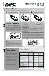
Positioning the <strong>UPS</strong><br />
The <strong>UPS</strong> is heavy. Select a location sturdy enough to handle the weight.<br />
Do not operate the <strong>UPS</strong> where there is excessive dust or the temperature and humidity are outside the<br />
specified limits.<br />
PLACEMENT<br />
0º- 40ºC (32º-104ºF)<br />
0-95% Relative<br />
Humidity<br />
2.5cm (1in)<br />
1
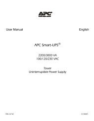
Connecting Equipment and Power to the <strong>UPS</strong><br />
SMART-<strong>UPS</strong> REAR PANEL<br />
230V MODELS 120V/100V MODELS<br />
<br />
1. Plug in the battery connector .<br />
<br />
2. Connect equipment to the <strong>UPS</strong>. Note: Do not connect a laser printer to the <strong>UPS</strong>. A laser<br />
printer draws significantly more power than other types of equipment and may overload<br />
the <strong>UPS</strong>.<br />
3. Add any optional accessories to the <strong>Smart</strong>-Slot .<br />
4. Using the power cord, plug the <strong>UPS</strong> into a two-pole, three-wire, grounded receptacle only.<br />
Avoid using extension cords.<br />
• 230V models: A utility connector plug is included for use on servers with permanently attached<br />
power cords.<br />
• 120V/100V models: The power cord is permanently attached to the rear panel of the <strong>UPS</strong>.<br />
5. Turn on all connected equipment. To use the <strong>UPS</strong> as a master ON/OFF switch, be sure all connected<br />
equipment is switched ON. The equipment will not be powered until the <strong>UPS</strong> is turned<br />
on.<br />
6. To power up the <strong>UPS</strong> press the button on the front panel.<br />
• The <strong>UPS</strong> charges its battery when it is connected to utility power. The battery charges to<br />
90% capacity during the first three hours of normal operation. Do not expect full battery run<br />
capability during this initial charge period.<br />
• 120V Models: Check the site wiring fault LED located on the rear panel. It lights up if the<br />
<strong>UPS</strong> is plugged into an improperly wired utility power outlet. Refer to Troubleshooting in<br />
this manual.<br />
7. For additional computer system security, install PowerChutePlus ® <strong>UPS</strong> Power Management and<br />
Diagnostic Software.<br />
2
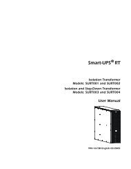
BASIC CONNECTORS<br />
Serial Port<br />
External Battery<br />
Pack Connector<br />
TVSS Screw<br />
USB Port<br />
Power management software and interface kits can be used<br />
with the <strong>UPS</strong>. Use only interface kits supplied or approved<br />
by <strong>APC</strong>.<br />
Use the <strong>APC</strong> supplied cable to connect to the Serial Port. DO NOT use a standard<br />
serial interface cable since it is incompatible with the <strong>UPS</strong> connector.<br />
Both Serial and USB Ports are provided. They cannot be used simultaneously.<br />
XL models: Use the battery pack connector to connect optional external<br />
battery pack(s). These units support up to ten external battery packs.<br />
See the <strong>APC</strong> web site, www.apc.com/support for the correct external<br />
battery pack model number for your <strong>UPS</strong>.<br />
The <strong>UPS</strong> features a transient voltage surge-suppression (TVSS) screw for<br />
connecting the ground lead on surge suppression devices such as telephone<br />
and network line protectors.<br />
When connecting grounding cable, disconnect the unit from the utility<br />
power outlet.<br />
3
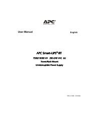
2: OPERATION<br />
SMART-<strong>UPS</strong> FRONT PANEL<br />
Online<br />
AVR Trim<br />
Power On<br />
Power Off<br />
Load Battery Charge<br />
The online LED illuminates when the <strong>UPS</strong> is supplying utility power to the connected<br />
equipment. If the LED is not lit, the <strong>UPS</strong> is either not turned ON, or is supplying<br />
battery power.<br />
This LED illuminates to indicate the <strong>UPS</strong> is compensating for a high utility voltage.<br />
4
AVR Boost<br />
On Battery<br />
Overload<br />
Replace Battery<br />
Battery<br />
Disconnected<br />
Automatic Self-Test<br />
This LED illuminates to indicate the <strong>UPS</strong> is compensating for a low<br />
utility voltage.<br />
When the on battery power LED is lit the <strong>UPS</strong> is supplying battery<br />
power to the connected equipment. When on battery, the <strong>UPS</strong> sounds<br />
an alarm—four beeps every 30 seconds.<br />
The LED illuminates and the <strong>UPS</strong> emits a sustained alarm tone when<br />
an overload condition occurs.<br />
Failure of a battery self-test causes the <strong>UPS</strong> to emit short beeps for<br />
one minute and the replace battery LED illuminates. Refer to Troubleshooting<br />
in this manual.<br />
The replace battery LED flashes and short beep is emitted every two<br />
seconds to indicate the battery is disconnected.<br />
The <strong>UPS</strong> performs a self-test automatically when turned on, and every<br />
two weeks thereafter (by default).<br />
During the self-test, the <strong>UPS</strong> briefly operates the connected equipment<br />
on battery.<br />
If the <strong>UPS</strong> fails the self-test, the replace battery LED lights and<br />
immediately returns to online operation. The connected equipment is<br />
not affected by a failed test. Recharge the battery for 24 hours and<br />
perform another self-test. If it fails, the battery must be replaced.<br />
Manual Self-Test Press and hold the button for a few seconds to initiate the selftest.<br />
On Battery Operation<br />
The <strong>Smart</strong>-<strong>UPS</strong> switches to battery operation automatically if the utility power fails. While running<br />
on battery, an alarm beeps four times every 30 seconds.<br />
Press the button (front panel) to silence the <strong>UPS</strong> alarm (for the current alarm only. If the utility<br />
power does not return, the <strong>UPS</strong> continues to supply power to the connected equipment until the battery<br />
is exhausted.<br />
If PowerChute is not being used you must manually save your files and power down before the <strong>UPS</strong><br />
turns off.<br />
DETERMINING ON BATTERY RUN TIME<br />
<strong>UPS</strong> battery life differs based on usage and environment. It is recommended that the battery/batteries<br />
be changed once every three years. See the <strong>APC</strong> web site, www.apc.com, for on battery run times.<br />
5
3: USER CONFIGURABLE ITEMS<br />
NOTE: SETTINGS ARE MADE THROUGH SUPPLIED POWERCHUTE SOFTWARE OR OPTIONAL SMART SLOT<br />
ACCESSORY CARDS.<br />
FUNCTION<br />
FACTORY<br />
DEFAULT<br />
Automatic Self-Test Every 14 days<br />
(336 hours)<br />
USER SELECTABLE CHOICES DESCRIPTION<br />
Every 7 days<br />
(168 hours),<br />
On Startup Only, No Self-<br />
Test<br />
<strong>UPS</strong> ID <strong>UPS</strong>_IDEN Up to eight characters to<br />
define the <strong>UPS</strong><br />
Date of Last Battery Replacement<br />
Minimum Capacity Before<br />
Return from Shutdown<br />
Voltage Sensitivity<br />
The <strong>UPS</strong> detects and<br />
reacts to line voltage<br />
distortions by transferring<br />
to battery operation to<br />
protect the connected<br />
equipment. Where power<br />
quality is poor, the <strong>UPS</strong><br />
may frequently transfer to<br />
battery operation. If the<br />
connected equipment can<br />
operate normally under<br />
such conditions, reduce<br />
the sensitivity setting to<br />
conserve battery capacity<br />
and service life.<br />
Manufacture<br />
Date<br />
Date of Battery Replacement<br />
mm/dd/yy<br />
0 percent 15, 30, 45, 50, 60, 75, 90<br />
percent<br />
Brightly lit: <strong>UPS</strong> is set to<br />
high sensitivity (default).<br />
Dimly lit: <strong>UPS</strong> is set to<br />
medium sensitivity.<br />
Off: Low battery<br />
warning interval is about<br />
eight minutes.<br />
6<br />
This function sets the interval<br />
at which the <strong>UPS</strong> will<br />
execute a self-test. Refer to<br />
your software manual for<br />
details.<br />
Use this field to uniquely<br />
identify the <strong>UPS</strong>, (ie. server<br />
name or location) for network<br />
management purposes.<br />
Reset this date when you<br />
replace the battery module.<br />
The <strong>UPS</strong> will charge its<br />
batteries to the specified<br />
percentage before return<br />
from a shutdown.<br />
To change the <strong>UPS</strong> sensitivity,<br />
press the voltage sensitivity<br />
button (rear panel).<br />
Use a pointed object (such as<br />
a pen) to do so.<br />
You can change the sensitivity<br />
level through Power-<br />
Chute software.<br />
Alarm Control Enable Mute, Disable User can mute an ongoing<br />
alarm or disable all existing<br />
alarms permanently.<br />
Shutdown Delay 90 seconds 0, 180, 270, 360, 450, 540,<br />
630 seconds<br />
Sets the interval between the<br />
time when the <strong>UPS</strong> receives<br />
a shutdown command and<br />
actual shutdown.
NOTE: SETTINGS ARE MADE THROUGH SUPPLIED POWERCHUTE SOFTWARE OR OPTIONAL SMART SLOT<br />
ACCESSORY CARDS.<br />
FUNCTION<br />
Low Battery Warning.<br />
PowerChute interface<br />
software provides automatic,<br />
unattended shutdown<br />
when approximately<br />
two minutes (by<br />
default) of battery operated<br />
run time remains.<br />
Synchronized Turn-on<br />
Delay<br />
FACTORY<br />
DEFAULT<br />
High Transfer Point 230V models:<br />
253VAC<br />
120V models:<br />
127VAC<br />
100V models:<br />
108VAC<br />
Low Transfer Point 230V models:<br />
208VAC<br />
120V models:<br />
106VAC<br />
100V models:<br />
92VAC<br />
Output Voltage 230V models:<br />
230VAC<br />
USER SELECTABLE CHOICES DESCRIPTION<br />
Brightly lit: Low battery<br />
warning interval is about two<br />
minutes.<br />
Dimly lit: Low battery<br />
warning interval is about five<br />
minutes.<br />
Off: Low battery<br />
warning interval is about<br />
eight minutes.<br />
Possible interval settings:<br />
2, 5, 8, 11, 14, 17, 20, 23<br />
minutes.<br />
0 seconds 60, 120, 180, 240, 300, 360,<br />
420 seconds<br />
230V models:<br />
257, 261, 265VAC<br />
120V models:<br />
130, 133, 136VAC<br />
100V models:<br />
110, 112, 114VAC<br />
230V models:<br />
196, 200, 204VAC<br />
120V models:<br />
97, 100, 103VAC<br />
100V models:<br />
86, 88, 90VAC<br />
230V models:<br />
220, 240VAC<br />
7<br />
The low battery warning<br />
beeps are continuous when<br />
two minutes of run time<br />
remain.<br />
To change the warning interval<br />
default setting, press<br />
the voltage sensitivity button<br />
(use a pointed object such as<br />
a pen to do so), while press-<br />
ing and holding the<br />
button (front panel).<br />
The <strong>UPS</strong> will wait the specified<br />
time after the return of<br />
utility power before turn-on<br />
(to avoid branch circuit<br />
overload).<br />
To avoid unnecessary battery<br />
usage, set the high<br />
transfer point higher if the<br />
utility voltage is chronically<br />
high and the connected<br />
equipment is known to work<br />
under this condition.<br />
Set the low transfer point<br />
lower if the utility voltage is<br />
chronically low and the connected<br />
equipment can tolerate<br />
this condition.<br />
230V models ONLY, allow<br />
the user to select the output<br />
voltage.
4: STORAGE, MAINTENANCE, AND TRANSPORTING<br />
Storage<br />
Store the <strong>UPS</strong> covered and positioned as for proper functioning, in a cool, dry location, with the batteries<br />
fully charged.<br />
At -15 to +30 °C (+5 to +86 °F), charge the <strong>UPS</strong> battery every six months.<br />
At +30 to +45 °C (+86 to +113 °F), charge the <strong>UPS</strong> battery every three months.<br />
Replacing the Battery Module<br />
This <strong>UPS</strong> has an easy to replace, hot-swappable battery module. Replacement is a safe procedure,<br />
isolated from electrical hazards. You may leave the <strong>UPS</strong> and connected equipment on for this procedure.<br />
See your dealer or contact <strong>APC</strong> at the web site, www.apc.com/support for information on replacement<br />
battery modules.<br />
Once the battery is disconnected, the connected equipment is not protected from<br />
power outages.<br />
Be careful during the following steps-the battery module is heavy.<br />
REMOVING THE FRONT BEZEL AND BATTERY MODULE<br />
Step 1 Step 2<br />
8
1500VA Model<br />
Step 3<br />
<strong>1000VA</strong> Model<br />
Battery<br />
Terminals<br />
Step A<br />
Step 3<br />
9<br />
Pull the battery module out of the compartment<br />
until the back of the module is flush with the<br />
outer edges of the <strong>UPS</strong>.<br />
Disconnect the battery connector.<br />
Step B<br />
Disconnect the battery cable terminals before<br />
removing the battery module from the <strong>UPS</strong>.<br />
Note: The red cable connects to the red colorcoded<br />
terminal; the black cable connects to the<br />
black color-coded terminal. This will be important<br />
during the battery replacement procedure.<br />
Battery<br />
Terminals<br />
Be sure to deliver the spent battery to a recycling facility or ship it to <strong>APC</strong> in the replacement<br />
battery packing material.
REPLACING THE BATTERY MODULE<br />
To replace the battery module, reverse the directions above for Removing the Front Bezel and Battery<br />
Module.<br />
Disconnecting the Battery for Transport<br />
Always DISCONNECT THE BATTERY before shipping in compliance with U.S.<br />
Department of Transportation (DOT) regulations.<br />
The battery may remain in the <strong>UPS</strong>; it does not have to be removed.<br />
1. Shut down and disconnect any equipment attached to the <strong>UPS</strong>.<br />
2. Shut down and disconnect the <strong>UPS</strong> from the power supply.<br />
3. Unplug the battery connector<br />
(rear panel).<br />
For shipping instructions and to obtain appropriate packing materials contact <strong>APC</strong> at the web site,<br />
www.apc.com/support/contact.<br />
10
5: TROUBLESHOOTING<br />
Use the chart below to solve minor <strong>Smart</strong>-<strong>UPS</strong> installation and operation problems. Refer to the <strong>APC</strong><br />
web site, www.apc.com, for assistance with complex <strong>UPS</strong> problems.<br />
PROBLEM AND POSSIBLE<br />
CAUSE<br />
<strong>UPS</strong> WILL NOT TURN ON<br />
Battery not connected properly.<br />
11<br />
SOLUTION<br />
Check that the battery connector (rear panel) is fully engaged.<br />
button not pushed. Press the button once to power the <strong>UPS</strong> and the connected equipment.<br />
<strong>UPS</strong> not connected to utility<br />
power supply.<br />
Check that the power cable from the <strong>UPS</strong> to the utility power supply is securely<br />
connected at both ends.<br />
Very low or no utility voltage. Check the utility power supply to the <strong>UPS</strong> by plugging in a table lamp. If the<br />
light is very dim, have the utility voltage checked.<br />
<strong>UPS</strong> WILL NOT TURN OFF<br />
Internal <strong>UPS</strong> fault. Do not attempt to use the <strong>UPS</strong>. Unplug the <strong>UPS</strong> and have it serviced immediately.<br />
<strong>UPS</strong> BEEPS OCCASIONALLY<br />
Normal <strong>UPS</strong> operation. None. The <strong>UPS</strong> is protecting the connected equipment.<br />
<strong>UPS</strong> DOES NOT PROVIDE EXPECTED BACKUP TIME<br />
The <strong>UPS</strong> battery is weak due<br />
to a recent outage or is near<br />
the end of its service life.<br />
Charge the battery. Batteries require recharging after extended outages.<br />
They wear faster when put into service often or when operated at elevated<br />
temperatures. If the battery is near the end of its service life, consider replacing<br />
the battery even if the replace battery LED is not yet lit.<br />
ALL LEDS ARE LIT AND THE <strong>UPS</strong> EMITS A CONSTANT BEEPING<br />
Internal <strong>UPS</strong> fault. Do not attempt to use the <strong>UPS</strong>. Turn the <strong>UPS</strong> off and have it serviced immediately.<br />
FRONT PANEL LEDS FLASH SEQUENTIALLY<br />
The <strong>UPS</strong> has been shut down<br />
remotely through software or<br />
an optional accessory card.<br />
None. The <strong>UPS</strong> will restart automatically when utility power returns.<br />
ALL LEDS ARE OFF AND THE <strong>UPS</strong> IS PLUGGED INTO A WALL OUTLET<br />
The <strong>UPS</strong> is shut down and the<br />
battery is discharged from an<br />
extended outage.<br />
None. The <strong>UPS</strong> will return to normal operation when the power is restored<br />
and the battery has a sufficient charge.
PROBLEM AND POSSIBLE<br />
CAUSE<br />
12<br />
SOLUTION<br />
THE OVERLOAD LED IS LIT AND THE <strong>UPS</strong> EMITS A SUSTAINED ALARM TONE<br />
The <strong>UPS</strong> is overloaded. The connected equipment exceeds the specified “maximum load” as defined<br />
in Specifications at the <strong>APC</strong> web site, www.apc.com.<br />
The alarm remains on until the overload is removed. Disconnect nonessential<br />
equipment from the <strong>UPS</strong> to eliminate the overload.<br />
The <strong>UPS</strong> continues to supply power as long as it is online and the circuit<br />
breaker does not trip; the <strong>UPS</strong> will not provide power from batteries in the<br />
event of a utility voltage interruption.<br />
If a continuous overload occurs while the <strong>UPS</strong> is on battery, the unit turns<br />
off output in order to protect the <strong>UPS</strong> from possible damage.<br />
THE REPLACE BATTERY LED IS LIT<br />
Replace Battery LED flashes<br />
and short beep is emitted every<br />
two seconds to indicate the<br />
battery is disconnected.<br />
Check that the battery connectors are fully engaged.<br />
Weak battery. Allow the battery to recharge for 24 hours. Then, perform a self-test. If the<br />
problem persists after recharging, replace the battery.<br />
Failure of a battery self-test. The <strong>UPS</strong> emits short beeps for one minute and the replace battery LED<br />
illuminates. The <strong>UPS</strong> repeats the alarm every five hours. Perform the selftest<br />
procedure after the battery has charged for 24 hours to confirm the<br />
replace battery condition. The alarm stops and the LED clears if the battery<br />
passes the self-test.<br />
THE SITE WIRING FAULT LED IS LIT<br />
The site wiring LED is lit<br />
(rear panel).<br />
120V models only.<br />
THE INPUT CIRCUIT BREAKER TRIPS<br />
The plunger on the circuit<br />
breaker (located above the input<br />
cable connection) pops out.<br />
The <strong>UPS</strong> is plugged into an improperly wired utility power outlet. Wiring<br />
faults detected include missing ground, hot-neutral polarity reversal, and<br />
overloaded neutral circuit. Contact a qualified electrician to correct the<br />
building wiring.<br />
Reduce the load on the <strong>UPS</strong> by unplugging equipment and press the<br />
plunger in.<br />
AVR BOOST OR AVR TRIM LEDS LIGHT<br />
AVR Boost or Trim LEDs light Have qualified service personnel check your facility for electrical prob-<br />
Your system is experiencing<br />
lems. If the problem continues, contact the utility company for further<br />
excessive periods of low r high<br />
assistance.<br />
voltage.
PROBLEM AND POSSIBLE<br />
CAUSE<br />
UTILITY CIRCUIT BREAKER TRIPS<br />
Utility circuit breaker trips during<br />
normal operation.<br />
13<br />
SOLUTION<br />
100V models: In order to operate at the full VA rating of the 1500VA<br />
product, the supplied 15A plug must be replaced with a 20A plug. This<br />
change must be performed by qualified service personnel.<br />
<strong>UPS</strong> OPERATES ON BATTERY ALTHOUGH NORMAL LINE VOLTAGE EXISTS<br />
<strong>UPS</strong> input circuit breaker tripped. Reduce the load on the <strong>UPS</strong> by unplugging equipment and resetting the<br />
circuit breaker (on the back of <strong>UPS</strong>) by pressing the plunger in.<br />
Very high, low, or distorted line<br />
voltage. Inexpensive fuel powered<br />
generators can distort the voltage.<br />
BATTERY CHARGE AND BATTERY LOAD LEDS FLASH SIMULTANEOUSLY<br />
<strong>UPS</strong> has shutdown.<br />
The internal temperature of the<br />
<strong>UPS</strong> has exceeded the allowable<br />
threshold for safe operation.<br />
DIAGNOSTIC UTILITY VOLTAGE FEATURE<br />
Utility Voltage<br />
Move the <strong>UPS</strong> to a different outlet on a different circuit. Test the input<br />
voltage with the utility voltage display (see below). If acceptable to the<br />
connected equipment, reduce the <strong>UPS</strong> sensitivity.<br />
Check that the room temperature is within the specified limits for operation.<br />
Check that the <strong>UPS</strong> is properly installed allowing for adequate ventilation.<br />
Allow the <strong>UPS</strong> to cool down. Restart the <strong>UPS</strong>. If the problem continues<br />
contact <strong>APC</strong> at, www.apc.com/supoport.<br />
The <strong>UPS</strong> has a diagnostic feature that displays the utility voltage. Plug<br />
the <strong>UPS</strong> into the normal utility power.<br />
Press and hold the button to view the utility voltage bar graph display.<br />
After a few seconds the five-LED, Battery Charge, , display<br />
on the right of the front panel shows the utility input voltage.<br />
Refer to the figure at left for the voltage reading (values are not listed on<br />
the <strong>UPS</strong>).<br />
The display indicates the voltage is between the displayed value on the<br />
list and the next higher value.<br />
Three LEDs light, indicating utility voltage within the normal range.<br />
If no LEDs are lit and the <strong>UPS</strong> is plugged into a working utility power<br />
outlet, the line voltage is extremely low.<br />
If all five LEDs are lit, the line voltage is extremely high and should be<br />
checked by an electrician.<br />
The <strong>UPS</strong> starts a self-test as part of this procedure. The self-test does not affect the voltage display.
Service<br />
If the <strong>UPS</strong> requires service do not return it to the dealer. Instead, follow these steps:<br />
1. Review the problems discussed in the Troubleshooting section of this manual to eliminate common<br />
problems.<br />
2. If the problem persists, contact <strong>APC</strong> Customer Service through the <strong>APC</strong> web site,<br />
www.apc.com/support.<br />
Note the model number of the <strong>UPS</strong>, the serial number, and the date purchased. If you call<br />
<strong>APC</strong> Customer Service, a technician will ask you to describe the problem and try to solve it<br />
over the phone, if possible. If this is not possible, the technician will issue a Returned Material<br />
Authorization Number (RMA#).<br />
If the <strong>UPS</strong> is under warranty, repairs are free. If not, there is a repair charge.<br />
3. Pack the <strong>UPS</strong> in its original packaging. If the original packing is not available, refer to the <strong>APC</strong><br />
web site, www.apc.com/support, for information about obtaining a new set.<br />
Pack the <strong>UPS</strong> properly to avoid damage in transit. Never use Styrofoam beads for packaging.<br />
Damage sustained in transit is not covered under warranty.<br />
Always DISCONNECT THE BATTERY before shipping in compliance with U.S.<br />
Department of Transportation (DOT) regulations.<br />
The battery may remain in the <strong>UPS</strong>; it does not have to be removed.<br />
4. Mark the RMA# on the outside of the package.<br />
5. Return the <strong>UPS</strong> by insured, prepaid carrier to the address given to you by Customer Service.<br />
Contacting <strong>APC</strong><br />
Refer to the information provided at the <strong>APC</strong> Internet site,<br />
http://www.apc.com/support.<br />
14
6: REGULATORY AND WARRANTY INFORMATION<br />
Regulatory Agency Approvals and Radio Frequency Warnings<br />
230V MODELS<br />
120V MODELS<br />
15<br />
This is a Class A product. In a domestic environment<br />
this product may cause radio interference, in which<br />
case the user may be required to take corrective actions.<br />
This equipment has been tested and found to comply with the limits for a Class A digital device, pursuant to part 15 of the<br />
FCC Rules. These limits are designed to provide reasonable protection against harmful interference when the equipment is<br />
operated in a commercial environment. This equipment generates, uses, and can radiate radio frequency energy and, if not<br />
installed and used in accordance with the instruction manual, may cause harmful interference to radio communications.<br />
Operation of this equipment in a residential area is likely to cause harmful interference in which case the user will be required<br />
to correct the interference at his own expense.<br />
Shielded signal cables must be used with this product to ensure compliance with the Class A FCC limits.<br />
100V MODELS
Declaration of Conformity<br />
Limited Warranty<br />
American Power Conversion (<strong>APC</strong>) warrants its products to be free from defects in materials and workmanship for a period of<br />
two years from the date of purchase. Its obligation under this warranty is limited to repairing or replacing, at its own sole option,<br />
any such defective products. To obtain service under warranty you must obtain a Returned Material Authorization<br />
(RMA) number from customer support. Products must be returned with transportation charges prepaid and must be accompanied<br />
by a brief description of the problem encountered and proof of date and place of purchase. This warranty does not apply<br />
to equipment that has been damaged by accident, negligence, or misapplication or has been altered or modified in any way.<br />
This warranty applies only to the original purchaser who must have properly registered the product within 10 days of purchase.<br />
EXCEPT AS PROVIDED HEREIN, AMERICAN POWER CONVERSION MAKES NO WARRANTIES, EXPRESSED OR<br />
IMPLIED, INCLUDING WARRANTIES OF MERCHANTABILITY AND FITNESS FOR A PARTICULAR PURPOSE.<br />
Some states do not permit limitation or exclusion of implied warranties; therefore, the aforesaid limitation(s) or exclusion(s)<br />
may not apply to the purchaser.<br />
EXCEPT AS PROVIDED ABOVE, IN NO EVENT WILL <strong>APC</strong> BE LIABLE FOR DIRECT, INDIRECT, SPECIAL, INCI-<br />
DENTAL, OR CONSEQUENTIAL DAMAGES ARISING OUT OF THE USE OF THIS PRODUCT, EVEN IF ADVISED<br />
OF THE POSSIBILITY OF SUCH DAMAGE. Specifically, <strong>APC</strong> is not liable for any costs, such as lost profits or revenue,<br />
loss of equipment, loss of use of equipment, loss of software, loss of data, costs of substitutes, claims by third parties, or otherwise.<br />
Entire contents copyright 2001 by American Power Conversion Corporation. All rights reserved. Reproduction in whole or in<br />
part without permission is prohibited.<br />
<strong>APC</strong>, <strong>Smart</strong>-<strong>UPS</strong>, and PowerChute are registered trademarks of American Power Conversion Corporation.<br />
All other trademarks are the property of their respective owners.<br />
16