
You also want an ePaper? Increase the reach of your titles
YUMPU automatically turns print PDFs into web optimized ePapers that Google loves.
<strong>XPC</strong> <strong>User</strong> <strong>Guide</strong><br />
For the : SN68SG2
Shuttle <strong>XPC</strong> EMI Test Statement<br />
Shuttle <strong>XPC</strong> have been through EMI tests according to the following series of regulations:<br />
N55022: 1998/A1: 2000/A2: 2003;AS/NZS CISPR22: 2004,EN55024: 1998/A1: 2001/A2: 2003;<br />
AS/NZS CISPR24:2002,FCC Rules CFR47 Part 15 Subpart B Class B,ANSI C63.4-2003,<br />
CNS13438(2006);CNS14336(2005). The items tested are illustrated as follows:<br />
(A) Voltage: AC 110V/60HZ & AC 230V/50HZ<br />
(B) Tested Product Information:<br />
Product Name: <strong>XPC</strong><br />
Status: Sample<br />
Model Name: SN68SG2 Series<br />
S/N: N/A<br />
CPU:<br />
External Frequency: 200 MHz<br />
AMD Athlon TM 64x2 : 6000+<br />
Clear CMOS button: 1 port<br />
USB 2.0 Port: 6 ports<br />
1394 Port: 1 port with 6 pins respectively, 1 port with 4 pins.<br />
LAN Port: 1 port (10Mbps/100Mbps/1000Mbps)<br />
Mic-In & Line-In & Earphone Ports: 1 port for each<br />
Center/Bass-Out Port: 1 port<br />
Surround-Out Port: 1 port<br />
Surround-Back Port: 1 port<br />
Front-Out Port: 1 port<br />
SPDIF-Out (Optical) Port: 1 port<br />
SPDIF-In (Optical) Port: 1 port<br />
DIMM Memory (optional): DDR2 2GB *2<br />
Power Cable: Detachable and Shielded (with a GND pin)<br />
D-Sub Port : 1920 X 1440 V: 75Hz<br />
All CPUs have completely been tested, and values offered by the worst EMI combination of<br />
CPU external frequency are listed as follows:<br />
Test Mode External Frequency CPU CPU Open/Close<br />
1 200MHz AMD Athlon TM 64X2 6000+ Close<br />
2 200MHz AMD Athlon TM 64X2 6000+ Open
(C) Remedy for the Tested Product & Its EMI Interference:<br />
Remedy: N/A<br />
EMI Interference:<br />
Crystal : 32.768 KHz(X5)/ 24.576 MHz(X4)/ 25 MHz(X6)<br />
(D) Supported Host Peripherals:<br />
Host Peripheral Product Name Model Name<br />
# 1 Case SN68SG2<br />
# 2 Power Supply PC40N250EV16DLA380<br />
# 3 Serial ATA II HITACHI HDT7225<br />
# 4 DVD Dual Player PX-712SA<br />
(E) Notices for Assembling Computers:<br />
1. Cases should be made of iron or other metal that has good electric conductivity.<br />
2. Cylinders in a case should be made of metal, and as having a mainboard mounted<br />
in a case, make sure screws are all utilized and fastened on a mainboard.<br />
3. An I/O shielding should be contacted with I/O metallic parts of a mainboard.<br />
4. Cables should appropriately be arranged and fixed in a case. Follow instructions:<br />
Leave IDE cables not crossed upon CPU and SDRAM;<br />
Leave power cables minimum in length, and not crossed upon a mainboard;<br />
Leave CPU fan cables minimum in length, and not near CPU;<br />
Leave cables on panels and other spare cables tied in a computer case.<br />
5. Make sure an EMI shielding attached to a case has properly been installed.<br />
6. Make sure a 5.25" or 3.5" FDD and screws are fastened to an EMI shielding.<br />
7. Make sure a case is closely in contact with EMI connected points.<br />
8. Make sure there is no cleft in a case which is not deformed.<br />
9. Make sure a PCI or AGP door is bound to a case.<br />
10. Make sure cables of other devices (fans or some others) are fixed in a case.
Shuttle ®<br />
<strong>XPC</strong> Installation <strong>Guide</strong><br />
Copyright<br />
Copyright © 2007 by Shuttle ® Inc. All Rights Reserved.<br />
No part of this publication may be reproduced, transcribed, stored in a retrieval system,<br />
translated into any language, or transmitted in any form or by any means, electronic,<br />
mechanical, magnetic, optical, chemical, photocopying, manual, or otherwise, without prior<br />
written permission from Shuttle ® Inc.<br />
Disclaimer<br />
Shuttle ® Inc. shall not be liable for any incidental or consequential damages resulting from<br />
the performance or use of this product.<br />
This company makes no representations or warranties regarding the contents of this manual.<br />
Information in this manual has been carefully checked for reliability; however, no<br />
guarantee is given as to the correctness of the contents. In the interest of continued product<br />
improvement, this company reserves the right to revise the manual or include changes in<br />
the specifications of the product described within it at any time without notice and without<br />
obligation to notify any person of such revision or changes. The information contained in<br />
this manual is provided for general use by customers.<br />
This device complies with Part 15 of the FCC Rules, Operation is subject to the following<br />
two conditions:<br />
1. This device may not cause harmful interference.<br />
2. This device must accept any interference received, including interference that may<br />
cause undesired operation.<br />
Trademarks<br />
Shuttle is a registered trademark of Shuttle Inc.<br />
Intel and Pentium are registered trademarks of Intel Corporation.<br />
PS/2 is a registered trademark of IBM Corporation.<br />
AWARD is a registered trademark of Award Software Inc.<br />
Microsoft and Windows are registered trademarks of Microsoft Corporation.<br />
General Notice<br />
Other brand and product names used herein are for identification purposes only and may<br />
be trademarks of their respective owners.
Safety Information<br />
Read the following precautions before setting up a Shuttle <strong>XPC</strong>.<br />
CAUTION<br />
Incorrectly replacing the battery may damage this computer. Replace only with<br />
the same or equivalent as recommended by Shuttle. Dispose of used batteries<br />
according to the manufacturer's instructions.<br />
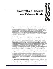
Installation Notices<br />
Do not place this device underneath<br />
heavy loads or in an unstable position.<br />
Do not expose this device to high<br />
levels of direct sunlight, high-humidity<br />
or wet conditions.<br />
Do not use or expose this device<br />
around magnetic fields as magnetic<br />
interference may affect the<br />
performance of the device.<br />
Do not block the air vents to this<br />
device or impede the airflow in<br />
any way.
TABLE OF CONTENTS<br />
1 Driver and Software Installation........................................................................... 1<br />
1.1 Mainboard Driver CD ..................................................................................... 2<br />
1.1.1 Install Mainboard Software ..................................................................... 2<br />
Appendix .................................................................................................................. 3<br />
Enter the BIOS ..................................................................................................... 3<br />
THE MAIN MENU ................................................................................................. 4<br />
Standard CMOS Features .............................................................................. 6<br />
Advanced BIOS Features ............................................................................... 9<br />
Advanced Chipset Features ..........................................................................11<br />
Integrated Peripherals .................................................................................. 13<br />
Power Management Setup ........................................................................... 17<br />
PnP/PCI Configurations ............................................................................... 19<br />
PC Health Status .......................................................................................... 21<br />
Frequency/Voltage Control ........................................................................... 22<br />
Load Optimized Defaults .............................................................................. 24<br />
Set Supervisor/<strong>User</strong> Password ..................................................................... 24<br />
Save & Exit Setup ........................................................................................ 25<br />
Exit Without Saving ...................................................................................... 25
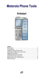
1.1 Mainboard Driver CD<br />
The Mainboard Driver CD contains all the motherboard driver necessary to optimize<br />
the performance of this <strong>XPC</strong> in a Windows(R) OS. Install these drivers after installing<br />
Microsoft(R) Windows(R).<br />
Navigation Bar Description :<br />
1 Driver and Software Installation<br />
Note: The CD contents attached in SN68SG2 mainboard are subject<br />
to change without notice.<br />
Install Mainboard Software - nVIDIA Chipset Driver,<br />
High Definition Audio Driver.<br />
Install Utility - <strong>XPC</strong> Tools.<br />
Manual - SN68SG2 user's guide and nVIDIA manual in PDF format.<br />
Link to Shuttle Homepage - Link to shuttle website homepage.<br />
Browse this CD - Allows you to see contents of this CD.<br />
1<br />
English
English<br />
1.1.1 Install Mainboard Software<br />
2<br />
Insert the attached CD into your CD-ROM drive. The CD AutoRun screen should<br />
appear. If the AutoRun screen does not appear, double click on Autorun icon in<br />
My Computer to bring up Shuttle Main-board Software Setup screen.<br />
Click the “Install Main-board Software“ bar. Individually install the following<br />
drivers.<br />
Install nVIDIA Chipset Driver<br />
Install High Definition Audio Driver
BIOS Settings<br />
The SN68SG2 BIOS ROM has a built-in Setup program that allows users to modify<br />
basic system configuration. This information is stored in battery-backed RAM so that it<br />
retains Setup information even if the system power is turned off.<br />
The system BIOS manages and executes a variety of hardware related functions<br />
including:<br />
System date and time<br />
Hardware execution sequence<br />
Power management functions<br />
Allocation of system resources<br />
Enter the BIOS<br />
Appendix<br />
To enter the BIOS (Basic Input / Output System) utility, follow these steps:<br />
Step1. Power on the computer. The system will perform its POST (Power-On<br />
Self Test) routine checks.<br />
Step2. Press the key immediately, or at the following message:<br />
Press DEL to enter SETUP, or simultaneously press ,,<br />
keys<br />
Note 1. If you miss the train of words mentioned in step2 (the message disappears<br />
before you can respond) and you still wish to enter BIOS Setup,<br />
restart the system and try again by turning the computer OFF and<br />
ON again or by pressing the switch located at the<br />
computer’s front-panel. You may also reboot by simultaneously<br />
pressing the ,, keys simultaneously.<br />
Note 2. If you do not press the keys in time and system does not boot, the<br />
screen will prompt an error message, and you will be given the<br />
following options:<br />
"Press F1 to Continue, DEL to Enter Setup”<br />
Step3. When you enter the BIOS program, the CMOS Setup Utility will display the<br />
Main Menu, as shown in the next section.<br />
3<br />
English
English<br />
4<br />
The Main Menu<br />
Once you enter the AwardBIOS(tm) CMOS Setup Utility, the Main Menu<br />
will appear on the screen. The Main Menu allows you to select from several<br />
setup functions and two exit choices. Use the arrow keys to select<br />
among the items and press to accept and enter the sub-menu.<br />
Note that a brief description of each highlighted selection appears at the<br />
bottom of the screen.<br />
Setup Items<br />
The main menu includes the following main setup categories. Recall that<br />
some systems may not include all entries.<br />
Standard CMOS Features<br />
Use this menu for basic system configuration.<br />
Advanced BIOS Features<br />
Use this menu to set the Advanced Features available on your system.<br />
Advanced Chipset Features<br />
Use this menu to change the values in the chipset registers and optimize<br />
your system's performance.<br />
Integrated Peripherals<br />
Use this menu to specify your settings for integrated peripherals.<br />
Power Management Setup<br />
Use this menu to specify your power management settings.
PnP / PCI Configurations<br />
This entry appears if your system supports PnP / PCI.<br />
PC Health Status<br />
This entry displays the current system temperature, Voltage, and FAN<br />
settings.<br />
Frequency/Voltage Control<br />
Use this menu to specify your settings for Frequency/Voltage control.<br />
Load Optimized Defaults<br />
Use this menu to load the BIOS default values that are factory-set for optimal<br />
system operation. While Award has designed the custom BIOS to<br />
maximize performance, the factory has the right to change these defaults<br />
to meet users' needs.<br />
Set Supervisor / <strong>User</strong> Password<br />
Use this menu to change, set, or disable password protection. This allows<br />
you to limit access to the system and Setup, or only to Setup.<br />
Save & Exit Setup<br />
Save CMOS value changes in CMOS and exit from setup.<br />
Exit Without Saving<br />
Abandon all CMOS value changes and exit from setup.<br />
5<br />
English
English<br />
Standard CMOS Features<br />
6<br />
The items in the Standard CMOS Setup Menu are divided into several<br />
categories. Each category includes none, one or more than one setup<br />
items. Use the arrow keys to highlight the item and then use the <br />
or keys to select the value you want in each item.<br />
Date<br />
<br />
Set the system date. Note that the 'Day' automatically changes when<br />
you set the date.<br />
Time<br />
<br />
The time is converted based on the 24-hour military-time clock.<br />
For example, 5 p.m. is 17:00:00.<br />
IDE Channel 0 Master/Slave<br />
Options are in its sub-menu.<br />
Press to enter the sub-menu of detailed options.<br />
Drive A<br />
Select the type of floppy disk drive installed in your system.<br />
The choice: None, 1.44M, 3.5 in, or 2.88M, 3.5 in.<br />
Halt On<br />
Select the situation in which you want the BIOS to stop the POST<br />
process and notify you.<br />
The choice: All Errors, No Errors, All, But Keyboard<br />
or All, But Diskette.
Base/Extended/Total Memory<br />
Theseitems are automatically detected by the system at start up time.<br />
These are display-only fields. You can't make change to these fields.<br />
******************************************************<br />
IDE Adapters<br />
The IDE adapters control the hard disk drive. Use a separate sub-menu<br />
to configure each hard disk drive.<br />
IDE HDD Auto-Detection<br />
Press to auto-detect HDD on this channel. If detection is<br />
successful, it fills the remaining fields on this menu.<br />
Press Enter<br />
IDE Channel 0 Master<br />
Selecting 'manual' lets you set the remaining fields on this screen and<br />
select the type of fixed disk. "<strong>User</strong> Type" will let you select the number of<br />
cylinders, heads, etc., Note: PRECOMP=65535 means<br />
NONE !<br />
The choice: None, Auto, or Manual.<br />
Access Mode<br />
Choose the access mode for this hard disk.<br />
The choice: CHS, LBA, Large, or Auto.<br />
Capacity<br />
Disk drive capacity (Approximated). Note that this size is usually slightly<br />
greater than the size of a formatted disk given by a disk checking program.<br />
Auto-Display your disk drive size.<br />
The following options are selectable only if the 'IDE Primary Master'<br />
item is set to 'Manual'<br />
Cylinder<br />
Set the number of cylinders for this hard disk.<br />
Min = 0, Max = 65535<br />
Head<br />
Set the number of read/write heads.<br />
Min = 0, Max = 255<br />
7<br />
English
English<br />
8<br />
Precomp<br />
Warning: Setting a value of 65535 means no hard disk.<br />
Min = 0, Max = 65535<br />
Landing zone<br />
Set the Landing zone size.<br />
Min = 0, Max = 65535<br />
Sector<br />
Number of sector per track.<br />
Min = 0, Max = 255<br />
******************************************************
Advanced BIOS Features<br />
This section allows you to configure your system for basic operation. You<br />
have the opportunity to select the system's default speed, boot-up sequence,<br />
keyboard operation, shadowing, and security.<br />
Removable Device Priority<br />
Options are in its sub-menu.<br />
Press to enter the sub-menu of detailed options.<br />
Hard Disk Boot Priority<br />
This item allows you to select Hard Disk Book Device Priority.<br />
CD-ROM Boot Priority<br />
This item allows you to select CD-ROM Book Device Priority.<br />
Bios Write Protect<br />
This item allows you to enable or disable the Bios Write Protect.<br />
If you want to flash BIOS, you must set it [Disabled].<br />
The choice: Enabled or Disabled.<br />
Quick Power On Self Test<br />
This item speeds up Power-On Self Test (POST) after you power on the<br />
computer. If it is set to enabled, BIOS will shorten or skip some check<br />
items during POST.<br />
The choice: Enabled or Disabled.<br />
9<br />
English
English<br />
10<br />
First/Second/Third Boot Device<br />
The BIOS attempts to load the operating system from the devices in the<br />
sequence selected in these items.<br />
The Choice: NVIDIA Boot Age, Hard Disk, CDROM, Legacy LAN,<br />
Removable or Disabled.<br />
Boot Other Device<br />
Select Your Boot Device Priority.<br />
The choice: Enabled or Disabled.<br />
Boot Up Floppy Seek<br />
Seeks disk drives during boot-Up. Disabling speed boots up. Enabled tests<br />
floppy drives to determine whether they have 40 or 80 tracks.<br />
The choice: Enabled or Disabled.<br />
Security Option<br />
Select whether the password is required every time the system boots or<br />
only when you enter setup.<br />
System The system will not boot and access to Setup will be<br />
denied if the correct password is not entered promptly.<br />
Setup The system will boot, but access to Setup will be<br />
denied if the correct password is not entered promptly.<br />
The choice: System or Setup.<br />
Note :To disabled security, select PASSWORD SETTING at Main Menu,<br />
and then you will be asked to enter password. Do not type anything<br />
and just press ; it will disable security.<br />
Once the security is disabled, the system will boot, and you can<br />
enter Setup freely.
Advanced Chipset Features<br />
This section allows you to configure the system based on the specific features<br />
of the installed chipset. This chipset manages bus speeds and access to system<br />
memory resources, such as DRAM and the external cache. It also coordinates<br />
communications between the conventional ISA bus and the PCI bus. It<br />
states that these items should never need to be altered.<br />
The default settings have been chosen because they provide the best operating<br />
conditions for your system. If you discovered that data was being lost<br />
while using your system, you might consider making any changes.<br />
iGPU Frame Buffer Control<br />
This item allows you to set the iGPU Frame Buffer Control.<br />
The choice: Auto or Manual.<br />
Frame Buffer Size<br />
This item allows you to set the Frame Buffer Size.<br />
The choice: 64M, 128M, 256M or Disabled.<br />
K8 NB HT Speed<br />
This item allows you to set the NB HT Speed.<br />
The choice: Auto, 1x~5x.<br />
K8NB HT Width<br />
This item allows you to set the NB HT Width.<br />
The choice: 8 8 or 16 16.<br />
11<br />
English
English<br />
12<br />
DRAM Configuration<br />
Options are in its sub-menu.<br />
Press to enter the sub-menu of detailed options.<br />
Timing Mode<br />
The Choice: Auto or MaxMemClk.<br />
Memory Clock value or Limi<br />
Setting platform Memclock.<br />
The Choice: DDR533, DDR667 or DDR800.<br />
DDRII Timing Item<br />
The Choice: Enabled or Disabled.<br />
TwTr Command Delay<br />
The Choice: 1~3 bus clocks.<br />
Trfc0 for DIMM0<br />
The Choice: 75ns, 105ns, 127.5ns, 195ns, or 327.5ns.<br />
Trfc1 for DIMM1<br />
The Choice: 75ns, 105ns, 127.5ns, 195ns, or 327.5ns.<br />
(Twr) Write Recovery Time<br />
The Choice: 3~6 bus clocks.<br />
(Trtp) Precharge Time<br />
The Choice: 2~3 clocks.<br />
(Trc) Row Cycle Time<br />
The Choice: 11~26 bus clocks.<br />
(Trcd)RAS to CAS R/W Delay<br />
The Choice: 3~6 clocks.<br />
(Trrd)RAS to RAS Delay<br />
The Choice: 2~5 clocks.<br />
(Trp)Row Precharge Time<br />
The Choice: 3~6 clocks.<br />
(Tras)Minimum RAS Active Time<br />
The Choice: 5~18 bus clocks.
Integrated Peripherals<br />
IDE Function Setup<br />
Options are in its sub-menu.<br />
Press to enter the sub-menu of detailed options.<br />
OnChip IDE Channel 0<br />
The chipset contains a PCI IDE interface with support to two IDE channels.<br />
Select Enabled to activate the primary IDE interface. select Disabled to<br />
deactivate this interface.<br />
The Choice: Enabled or Disabled.<br />
Primary Master/Slave PIO<br />
The four IDE PIO (Programmed Input/Output) fields let you set a PIO mode<br />
(0-4) for each of the four IDE devices that the onboard IDE interface<br />
supports. Modes 0 through 4 provide successively increased performance.<br />
In Auto mode, the system automatically determines the best mode for<br />
each device.<br />
The choice: Auto, Mode 0, Mode 1, Mode 2, Mode 3, or Mode 4.<br />
Primary Master/Slave UDMA<br />
Ultra DMA/100 implementation is possible only if your IDE hard drive<br />
supports it and the operating environment includes a DMA driver (Windows<br />
95 OSR2 or a third-party IDE bus master driver). If both of your hard<br />
drive and your system software support Ultra DMA/100, select Auto to<br />
enable BIOS support.<br />
The choice: Auto or Disabled.<br />
13<br />
English
English<br />
14<br />
Serial-ATA Controller<br />
This item allows you to enable/disable the SATA transfer access.<br />
The choice: Enabled, or Disabled.<br />
IDE HDD Block Mode<br />
Block mode is also called block transfer, multiple commands, or multiple<br />
sector read/write. If your IDE hard drive supports block mode(most new<br />
drivers do), select Enabled for automatic detection of the optimal number<br />
of block read/write per sector the drive can support.<br />
The Choice: Enable or Disabled.<br />
MCP Storage Config<br />
Options are in its sub-menu.<br />
Press to enter the sub-menu of detailed options.<br />
SATA Operation Mode<br />
This item allows you to set the SATA Mode.<br />
The choice: IDE, RAID or AHCI.<br />
SATA Pri-Master/Slave<br />
This item allows you to set the SATA Pri-Master/Slave.<br />
The Choice: Enabled or Disabled.<br />
SATA Sec-Master/Slave<br />
This item allows you to set the SATA Sec-Master/Slave.<br />
The Choice: Enabled or Disabled.<br />
Init Display First<br />
This item is used to determine initial device when system power on.<br />
The choice: PCI Slot, Onboard or PCI-Ex.<br />
HD Audio<br />
This item allows you to control the HD Audio.<br />
The Choice: Auto or Disabled.<br />
MAC Lan<br />
This item allows you to control the MAC Lan.<br />
The Choice: Auto or Disabled.
Onboard FDC Controller<br />
This item specifices onboard floopy disk drive controller. This setting<br />
allows you to connect your floopy disk drives to the onboard floopy<br />
connector.<br />
The Choice: Enable or Disabled.<br />
Onboard Parallel Port<br />
This item allows you to determine onboard parallel port controller I/O<br />
address and interrupt request ( IRQ ).<br />
The choice: 378/IRQ7, 278/IRQ5, 3BC/IRQ7, or Disabled.<br />
Parallel Port Mode<br />
Select an operating mode for the onboard parallel (printer) port. Select<br />
Normal, Compatible, or SPP unless you are certain your hardware and<br />
software both support one of the other available modes.<br />
The choice: SPP, EPP, ECP, or ECP+EPP.<br />
ECP Mode Use DMA<br />
When the onboard parallel is set to ECP mode, the parallel port can use<br />
DMA3 or DMA1.<br />
The choice: 1 or 3.<br />
USB Device Setting<br />
Option are in its sub-menu.<br />
Pressto enter the sub-menu of detailed options.<br />
USB Operation Mode<br />
Auto decide USB device operation mode.<br />
High speed: If USB device was high speed device, then it operated on<br />
high speed mode.If USB device was full/low speed device,<br />
then it operated on full/low speed mode.<br />
Full/Low Speed: All of USB device operated on full/low speed mode.<br />
The choice: High speed or Full/Low Speed.<br />
*** USB Mass Storage Device Boot Setting ***<br />
UFDDA USB Floppy<br />
UFDDB USB Floppy<br />
15<br />
English
English<br />
16<br />
No Device<br />
Auto: According to contents of USB MSD decide boot up type.<br />
FDD Mode: The USB MSD always boot up as floppy disk.<br />
HDD Mode: The USB MSD always boot up as hard disk.<br />
The choice: Auto mode, FDD mode or HDD mode.
Power Management Setup<br />
The Power Management Setup allows you to configure your system to<br />
most effectively saving energy while operating in a manner consistent<br />
with your own style of computer use.<br />
ACPI Function<br />
This item allows you to enable/disable the Advanced Configuration and<br />
Power Management (ACPI).<br />
Always "Enabled".<br />
ACPI Suspend Type<br />
This item allows you to select sleep state when suspend.<br />
The choice: S1(POS) or S3(STR).<br />
Soft-Off By PBTN<br />
Pressing the power button for more than 4 seconds forces the system to<br />
enter the Soft-Off state when the system has " hung".<br />
The choice: Delay 4 Sec or Instant-Off.<br />
WOL(PME#) From Soft-Off<br />
If this item sets to Enable, the system power will be turned on when the<br />
LAN port receives an incoming signal. You have to connect the fax/modem<br />
to the mainboard Wake On LAN connector for this feature to work.<br />
The choice: Enabled or Disabled.<br />
17<br />
English
English<br />
18<br />
MAC Resume from S4/S5<br />
This item allows you to enable/disable the MAC Resume from S4/S5.<br />
The choice: Disabled or Enabled.<br />
Power-On by Alarm<br />
When this item enabled, your can set the date (day of the month) and<br />
time to turn on your system.<br />
The choice: Disabled or Enabled.<br />
Date(of Month) Alarm<br />
This item selects the alarm Date (day of the month).<br />
Key in a DEC number: Min=0, Max=31.<br />
Time(hh : mm : ss) Alarm<br />
This item selects the alarm Time.<br />
[hh] Key in a DEC number: Min=0, Max=23.<br />
[mm/ss] Key in a DEC number: Min=0, Max=59.<br />
PS2 Keyboard Power ON<br />
This item allows you to set the Keyboard Power On function.<br />
The choice: Disabled, password, or Hot KEY.<br />
KB Power ON Password<br />
This item allows you to set the KB Power On Password.<br />
Press" Enter" to set Password.<br />
Hot Key Power On<br />
This item allows you to set the Hot Key Power On.<br />
The choice: Any Key, Ctrl-F1~Ctrl-F12.<br />
PS2 Mouse Power ON<br />
This item allows you to set the the Mouse Power On function.<br />
The choice: Disabled or Enabled.<br />
PWRON After PWR-Fail<br />
This item allows you to select power on function when power fail.<br />
The choice: Off or On.
PnP/PCI Configurations<br />
This section describes the configuration of PCI bus system. PCI or Personal<br />
Computer Interconnection is a system which allows I/O devices to<br />
operate at the speed CPU itself keeps when CPU communicating with its<br />
own special components.<br />
This section covers some very technical items, and it is strongly recommended<br />
that only experienced users should make any changes to the<br />
default settings.<br />
Resource controlled By<br />
The Award Plug-and-Play BIOS has the capacity to automatically configure<br />
all of the boot and Plug-and-Play compatible devices. However, this<br />
capability means absolutely nothing unless you are using a Plug-and-Play<br />
operating system such as Windows 95.<br />
If you set this field to "manual" , choose specific resources by going into<br />
each of the sub-menu that follows this field (a sub-menu is proceeded by<br />
a ">").<br />
The choice: Auto(ESCD) or Manual.<br />
IRQ Resources<br />
When resources are controlled manually, assign each system interrupt a<br />
type, depending on the type of device using the interrupt.<br />
IRQ5/7/9/10/11/14 assigned to<br />
This item allows you to determine the IRQ assigned to the ISA bus and is<br />
not available to any PCI slot. Legacy ISA for devices is compliant with the<br />
original PC AT bus specification; PCI/ISA PnP for devices is compliant<br />
19<br />
English
English<br />
20<br />
with the Plug-and-Play standard whether designed for PCI or ISA bus<br />
architecture.<br />
The choice: PCI Device or Reserved.<br />
PCI/VGA Palette Snoop<br />
It determines whether the MPEG ISA/VESA VGA Cards can work with<br />
PCI/VGA or not. If you have MPEG ISA/VESA VGA Cards and PCI/VGA<br />
Card worked, Enable this field. Otherwise, please Disable it.<br />
The choice: Enabled or Disabled.<br />
INP Pin 1~4 Assignment<br />
This item allows you to set the INP Pin 1~4 Assignment.<br />
The choice: Auto, 3, 4, 5, 7, 9, 10, 11, 12, 14, or 15.<br />
** PCI Express relative items **<br />
Maximum Payload Size<br />
Set maximum TLP payload size for the PCI Express devices.<br />
The unit is byte.<br />
The choice: 128, 256, 512, 1024, 2048 or 4096.
PC Health Status<br />
CPU Fan Speed Control<br />
Here you can set the CPU Fan Speed.<br />
The choice: Smart Fan, Ultra-Low, Low, Mid, or Full.<br />
CPU Voltage<br />
+ 5V VIN<br />
3.3V VIN<br />
+12V VIN<br />
RAM Voltage<br />
Chipset Voltage<br />
5V SBVIN<br />
Voltage Battery<br />
System Temperature<br />
CPU Temperature<br />
CPU FAN Speed<br />
System FAN Speed Warning:<br />
Note: Before manually modifying<br />
the CPU fan setting, please<br />
make sure fan connectors<br />
are plug ged into the correct<br />
fan conne ctor on the<br />
mainboard.<br />
It is strongly recommended to<br />
disable 'Smart Fan' if you use<br />
an alternative fan to the default.<br />
21<br />
English
English<br />
Frequency/Voltage Control<br />
22<br />
CPU Frequency<br />
This item allows you to enable or disable the spread spectrum modulation.<br />
The choice: 200~300.<br />
Chipset Voltage Setting<br />
This item allows you to set the Chipset Voltage.<br />
The choice: Auto , 1.3V, 1.4V, or 1.5V.<br />
DDR2 Voltage Setting<br />
This item allows you to set the DDR2 Voltage.<br />
The choice: Auto, 1.825V~2.575V.<br />
CPU Voltage Setting<br />
This item allows you to set the CPU Voltage.<br />
The choice: Auto, +10mV~+400mV.<br />
CPU Spread Spectrum<br />
This item allows you to enable or disable the CPU spread spectrum.<br />
The Choice: Enabled or Disabled.<br />
PCIE Spread Spectrum<br />
This item allows you to enable or disable the PCIE spread spectrum.<br />
The Choice: Enabled or Disabled.
SATA Spread Spectrum<br />
This item allows you to enable or disable the SATA spread spectrum.<br />
The Choice: Enabled or Disabled.<br />
iGPU Spread Spectrum<br />
This item allows you to set the iGPU Spread Spectrum.<br />
The choice: Enabled or Disabled.<br />
PCIE Clock<br />
This item allows you to set the PCIE Clock.<br />
The choice: 100~150Mhz.<br />
23<br />
English
English<br />
Load Optimized Defaults<br />
Set Supervisor/<strong>User</strong> Password<br />
24<br />
When you press on this item, you will get a confirmation<br />
dialog box with a message similar to:<br />
Steps to set supervisor/user password are described as follows:<br />
New Password Setting:<br />
1. Press the key. A dialog box appears to ask you to “Enter password: “.<br />
2. Key in a new password.<br />
Load Optimized Defaults (Y/N) ? N<br />
Pressing 'Y' loads the default values that are factory-set for optimal<br />
performance system operation.<br />
The password can not be over eight characters or numbers.<br />
3. The system will then request you to confirm the new password by asking you to<br />
key in the new password again.<br />
4. Once the confirmation is completed, new code is in effect.
No Password Setting:<br />
5. If you want to delete the password, just press the key instead of<br />
typing a new password. Follow the procedure as above.<br />
If You Forget Password:<br />
6. If you forget your password, you must turn off the system and clear CMOS.<br />
Please refer to the tech notes at the end of section two for more information.<br />
Save & Exit Setup<br />
Exit Without Saving<br />
Pressing on this item asks for confirmation:<br />
SAVE to CMOS and EXIT (Y/N)? Y<br />
Pressing "Y" stores the selections made in the menus of CMOS - a special<br />
section of memory that stays on after you turn your system off. The next<br />
time you boot your computer, the BIOS configures your system according<br />
to the Setup selections stored in CMOS. After saving the values the<br />
system is restarted again.<br />
Pressing on this item asks for confirmation:<br />
Quit Without Saving (Y/N)? N<br />
This allows you to exit from Setup without storing in CMOS any change.<br />
The previous selections remain in effect. This exits from the Setup utility<br />
and restarts your computer.<br />
25<br />
English