Matrix™ UPS - APC Media
Matrix™ UPS - APC Media
Matrix™ UPS - APC Media

You also want an ePaper? Increase the reach of your titles
YUMPU automatically turns print PDFs into web optimized ePapers that Google loves.
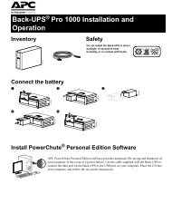
Matrix <strong>UPS</strong><br />
Models 3000 and 5000<br />
208/220–240 Vac, 50/60 Hz version<br />
User’s<br />
Manual
Important safety instructions!<br />
Please read this manual!<br />
Veuillez lire ce manuel!<br />
Bitte lesen Sie dieses Anleitungshandbuch!<br />
¡Se ruega leer este manual de instrucciones!<br />
This manual provides safety, installation, and operating instructions to help you get the<br />
fullest performance and service life that the <strong>UPS</strong> has to offer.<br />
PLEASE SAVE THIS MANUAL ! It includes important instructions for the safe use of<br />
this <strong>UPS</strong> and for obtaining factory service should the proper operation of the <strong>UPS</strong><br />
come into question. Down the road, service or storage issues may arise and require<br />
reference to this manual.<br />
CONSERVER CES INSTRUCTIONS ! Cette notice contient des instructions<br />
importantes concernant la sécurité.<br />
Radio frequency interference<br />
WARNING: Changes or modifications to this unit not expressly approved by the party<br />
responsible for compliance could void the user's authority to operate the equipment.<br />
NOTE: This equipment has been tested and found to comply with the limits for a Class<br />
A digital device pursuant to Part 15 of the FCC Rules. These limits are designed to<br />
provide reasonable protection against harmful interference when the equipment is<br />
operated in a commercial environment. This equipment generates, uses, and can radiate<br />
radio frequency energy and, if not installed and used in accordance with the instruction<br />
manual, may cause harmful interference to radio communications. Operation of this<br />
equipment in a residential area is likely to cause harmful interference in which case the<br />
user will be required to correct the interference at his own expense.<br />
Shielded cables must be used with this unit to ensure compliance with the<br />
Class A FCC limits.<br />
This digital apparatus does not exceed the Class A limits for radio noise emissions<br />
from digital apparatus set out in the Radio Interference Regulations of the Canadian<br />
Department of Communications.<br />
Le présent appareil numérique n'emet pas de bruits radioélectriques dépassant les<br />
limites applicables aux appareils numériques de la Class A prescrites dans le<br />
Règlement sur le brouillage radioélectrique édicte par le ministère dès Communications<br />
du Canada.
Limited Warranty<br />
American Power Conversion (<strong>APC</strong>) warrants its products to be free from defects in materials and<br />
workmanship for a period of two years from the date of purchase. Its obligation under this<br />
warranty is limited to repairing or replacing, at its own sole option, any such defective products.<br />
To obtain service under warranty you must obtain a Returned Material Authorization (RMA)<br />
number from <strong>APC</strong> or an <strong>APC</strong> service center. Products must be returned to <strong>APC</strong> or an <strong>APC</strong><br />
service center with transportation charges prepaid and must be accompanied by a brief description<br />
of the problem encountered and proof of date and place of purchase. This warranty does not<br />
apply to equipment which has been damaged by accident, negligence, or mis-application or has<br />
been altered or modified in any way. This warranty applies only to the original purchaser who<br />
must have properly registered the product within 10 days of purchase.<br />
EXCEPT AS PROVIDED HEREIN, AMERICAN POWER CONVERSION MAKES NO WARRANTIES,<br />
EXPRESS OR IMPLIED, INCLUDING WARRANTIES OF MERCHANTABILITY AND FITNESS FOR<br />
A PARTICULAR PURPOSE. Some states do not permit limitation or exclusion of implied warranties;<br />
therefore, the aforesaid limitation(s) or exclusion(s) may not apply to the purchaser.<br />
EXCEPT AS PROVIDED ABOVE, IN NO EVENT WILL <strong>APC</strong> BE LIABLE FOR DIRECT, INDIRECT,<br />
SPECIAL, INCIDENTAL, OR CONSEQUENTIAL DAMAGES ARISING OUT OF THE USE OF THIS<br />
PRODUCT, EVEN IF ADVISED OF THE POSSIBILITY OF SUCH DAMAGE. Specifically, <strong>APC</strong> is<br />
not liable for any costs, such as lost profits or revenue, loss of equipment, loss of use of<br />
equipment, loss of software, loss of data, costs of substitutes, claims by third parties, or otherwise.<br />
This warranty gives you specific legal rights and you may also have other rights which vary from<br />
state to state.<br />
Life Support Policy<br />
As a general policy, American Power Conversion (<strong>APC</strong>) does not recommend the use of any of<br />
its products in life support applications where failure or malfunction of the <strong>APC</strong> product can be<br />
reasonably expected to cause failure of the life support device or to significantly affect its safety<br />
or effectiveness. <strong>APC</strong> does not recommend the use of any of its products in direct patient care.<br />
<strong>APC</strong> will not knowingly sell its products for use in such applications unless it receives in writing<br />
assurances satisfactory to <strong>APC</strong> that (a) the risks of injury or damage have been minimized, (b)<br />
the customer assumes all such risks, and (c) the liability of American Power Conversion is<br />
adequately protected under the circumstances.<br />
Examples of devices considered to be life support devices are neonatal oxygen analyzers, nerve<br />
stimulators (whether used for anesthesia, pain relief, or other purposes), autotransfusion devices,<br />
blood pumps, defibrillators, arrhythmia detectors and alarms, pacemakers, hemodialysis systems,<br />
peritoneal dialysis systems, neonatal ventilator incubators, ventilators for both adults and infants,<br />
anesthesia ventilators, and infusion pumps as well as any other devices designated as “critical”<br />
by the U.S. FDA.<br />
Hospital grade wiring devices and leakage current may be ordered as options on many <strong>APC</strong><br />
<strong>UPS</strong> systems. <strong>APC</strong> does not claim that units with this modification are certified or listed as<br />
Hospital Grade by <strong>APC</strong> or any other organization. Therefore these units do not meet the<br />
requirements for use in direct patient care.
Table of Contents<br />
1.0 Introduction ............................................................................. 2<br />
2.0 Safety! Sécurité! Sicherheit! ¡Seguridad! .............................. 4<br />
3.0 Presentation ............................................................................. 8<br />
Isolation Unit (IU) ................................................................................................................................... 8<br />
Electronics Unit (EU) ........................................................................................................................... 10<br />
Battery Pack ............................................................................................................................................ 12<br />
4.0 Installation ............................................................................. 14<br />
Receiving inspection, Protection strategies, Moving the <strong>UPS</strong>, Placement ....................... 14<br />
Input voltage requirements ............................................................................................................... 16<br />
Installation procedures........................................................................................................................ 17<br />
Input hard wiring procedure ............................................................................................................ 18<br />
Input voltage tap selection—208 Vac, 50/60 Hz use only .................................................... 21<br />
Output wiring procedure ................................................................................................................... 22<br />
Module interconnections.................................................................................................................... 24<br />
Emergency Power Off (EPO) interface......................................................................................... 26<br />
Start-up ...................................................................................................................................................... 27<br />
5.0 Operation .............................................................................. 28<br />
Modes of operation .............................................................................................................................. 2 8<br />
Display and controls operation ....................................................................................................... 30<br />
6.0 <strong>UPS</strong> Monitoring ...................................................................... 38<br />
Computer Interface port ..................................................................................................................... 39<br />
7.0 Difficulty Difficulté Schwierigkeit Dificultad ...................... 40<br />
Troubleshooting Chart ........................................................................................................................ 44<br />
Fault messages ....................................................................................................................................... 45<br />
Replacing the Electronics Unit ......................................................................................................... 46<br />
Replacing or adding Battery Packs................................................................................................. 47<br />
Obtaining Service.................................................................................................................................. 48<br />
8.0 Storing the <strong>UPS</strong> ...................................................................... 49<br />
9.0 Specifications.......................................................................... 50<br />
Recharge and Run Times ................................................................................................................... 52<br />
1
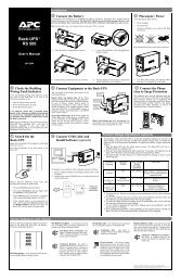
1.0 Introduction<br />
1.1 Overview<br />
The <strong>UPS</strong> is a high-power enhanced line-interactive uninterruptible power source<br />
which provides clean, reliable AC power to computer, data handling, and telecommunications<br />
loads. Normally, the <strong>UPS</strong> operates “on-line” and provides power derived<br />
from the input mains source, continuously regulating the load voltage to compensate<br />
for voltage fluctuations on the mains. A multilevel transformer tap changing circuit<br />
provides this regulation while attaining high levels of on-line efficiency. To adjust the<br />
load voltage, the <strong>UPS</strong> temporarily operates the load from battery power while an<br />
appropriate transformer tap change is made. If line conditions become unacceptable,<br />
the <strong>UPS</strong> transfers load power from the mains to the inverter (“on-battery” operation)<br />
synchronously and virtually seamlessly under all conditions. The voltage waveshape<br />
during on-battery operation is a low-distortion sine wave. Resynchronization and<br />
transfer of load power back to the mains is automatic when the line voltage is again<br />
within normal limits.<br />
A complete <strong>UPS</strong> system consists of three module types: an Electronics Unit (EU)<br />
mounted on top of an Isolation Unit (IU), and Battery Packs, which can be added to<br />
increase on-battery run time. The EU self-connects to the IU when mounted, and<br />
contains the <strong>UPS</strong>’s microprocessor controls, inverter, battery charger, transfer and tap<br />
changing circuits, remote interfaces, and the user control and display panel. The IU<br />
contains the <strong>UPS</strong>’s isolation transformer, EMI/RFI filtering and surge-suppression<br />
circuits, bypass circuit, and the mains and load wiring interfaces. The Battery Packs<br />
“daisy chain” from the EU using a heavy duty cable and lockable connector system.<br />
The Battery Packs and the EU communicate over modular-plug cables. Each Battery<br />
Pack contains four high-capacity batteries and microprocessor-controlled electronics<br />
for communications and battery pack monitoring.<br />
2<br />
Electronics Unit<br />
(EU)<br />
Isolation Unit<br />
(IU)<br />
Battery Packs
1.0 Introduction<br />
1.2 Hot swappable modules<br />
The IU is capable of autonomous operation and allows service or upgrade of the<br />
Electronics Unit without interruption of power to the load. In addition, a worn Battery<br />
Pack can be replaced, or new packs can be added, while maintaining power to the<br />
load. In the event of EU failure, functions controlled by the EU are automatically<br />
bypassed and the IU operates autonomously. For servicing, this bypass mode may be<br />
selected manually.<br />
1.3 Emergency Power Off (EPO)<br />
For applications where, for safety reasons, power to all room equipment may be cut<br />
off, the <strong>UPS</strong> provides a remote Emergency Power Off interface.<br />
1.4 Display<br />
Local <strong>UPS</strong> user interface is served by a display and control panel containing a back-lit<br />
2×16 character display and three buttons. Using the buttons, menus for displaying<br />
<strong>UPS</strong> status, <strong>UPS</strong> control commands, <strong>UPS</strong> setup, <strong>UPS</strong> tests and <strong>UPS</strong> diagnostics are<br />
shown. Critical <strong>UPS</strong> functions can be password protected. A loud audible alarm warns<br />
of operating modes that could result in the loss of power to the load without user<br />
intervention.<br />
1.5 Remote interfaces<br />
The <strong>UPS</strong> provides a full RS-232 communications computer interface. When used with<br />
PowerDoctor <strong>UPS</strong> monitoring software and a serially connected local DOS PC, the<br />
local display and control panel functions are duplicated and power quality events can<br />
be logged. PowerChute plus offers the features of PowerDoctor, and the control of<br />
orderly and unattended network or multi-user computer system shutdown. Also<br />
available for the <strong>UPS</strong> is the SNMP (Simple Network Management Protocol) Adapter to<br />
provide load-type independent remote monitoring and management over Ethernet or<br />
Token Ring based LANs or WANs capable of routing IP messages. Using any standard<br />
Network Management System (NMS) and the SNMP Adapter, the <strong>UPS</strong> is manageable<br />
through a single familiar interface—from across your building or across the world.<br />
3
2.0 Safety! ENGLISH<br />
4<br />
CAUTION!<br />
n To reduce the risk of electric shock, disconnect the Uninterruptible<br />
Power Source from the mains before installing computer interface signal cable (when<br />
used). Reconnect the power cord only after all signalling interconnections have been<br />
made.<br />
n Connect the Uninterruptible Power Source to a two-pole, three-wire grounding<br />
mains receptacle. The receptacle must be connected to appropriate branch protection<br />
(fuse or circuit breaker). Connection to any other type of receptacle may result in a<br />
shock hazard and may violate local electrical codes.<br />
n This Uninterruptible Power Source has an internal energy source<br />
(the battery) that cannot be de-energized by the user. The output may be energized<br />
when the unit is not connected to a mains supply.<br />
n To properly deenergize the Uninterruptible Power Source in an emergency, move<br />
the rear panel I/O switch to the O (off) position and disconnect the power cord from<br />
the mains.<br />
n Avoid installing the Uninterruptible Power Source in locations where there is<br />
water or excessive humidity.<br />
n Do not allow water or any foreign object to get inside the Uninterruptible Power<br />
Source. Do not put objects containing liquid on or near the unit.<br />
n To reduce the risk of overheating the Uninterruptible Power Source, avoid<br />
exposing the unit to the direct rays of the sun. Avoid installing the unit near heat<br />
emitting appliances such as a room heater or stove.
2.0 Sécurité! FRANÇAIS<br />
ATTENTION!<br />
n Pour réduire le risque d’électrocution, débranchez la prise principale de la source<br />
d’alimentation permanente (Uninterruptible Power Source), avant d’installer le câble<br />
d’interface allant à l’ordinateur (si utilisé). Ne rebranchez le bloc d’alimentation<br />
qu’après avoir effectué toutes les connections.<br />
n Branchez la source d’alimentation permanente (<strong>UPS</strong>) dans une prise de courant à<br />
3 dérivations (deux pôles et la terre). Cette prise doit être munie d’une protection<br />
adéquate (fusible ou coupe-circuit). Le branchement dans tout autre genre de prise<br />
pourrait entraîner un risque d’électrocution et peut constituer une infraction à la<br />
réglementation locale concernant les installations électriques.<br />
n Cette source d’alimentation permanente (<strong>UPS</strong>) est munie d’une source d’énergie<br />
interne (accumulateur) qui ne peut pas être désactivée par l’utilisateur. La prise de<br />
sortie peut donc être sous tension même lorsque l’appareil n’est pas branché.<br />
n En cas d’urgence, pour désactiver correctement la source d’alimentation permanente<br />
(<strong>UPS</strong>), poussez l’interrupteur du panneau arrière sur la position O (Off) et<br />
débranchez le cordon d’alimentation principal.<br />
n Ne pas installer la source d’alimentation permanente (<strong>UPS</strong>) dans un endroit où il y<br />
a de l’eau ou une humidité excessive.<br />
n Ne pas laisser de l’eau ou tout objet pénétrer dans la source d’alimentation<br />
permanente (<strong>UPS</strong>). Ne pas placer de récipients contenant un liquide sur cet appareil,<br />
ni à proximité de celui-ci.<br />
n Pour éviter une surchauffe de la source d’alimentation permanente (<strong>UPS</strong>),<br />
conservez-la à l’abri du soleil. Ne pas installer à proximité d’appareils dégageant de la<br />
chaleur tels que radiateurs ou appareils de chauffage.<br />
5
2.0 Sicherheit! DEUTSCH<br />
6<br />
VORSICHT!<br />
n Um die Gefahr eines elektrischen Schlages auf ein Minimum zu reduzieren, die<br />
unterbrechungsfreie Stromversorgung vom Stromnetz trennen, bevor ggf. ein<br />
Computer-Schnittstellensignalkabel angeschlossen wird. Das Netzkabel erst nach<br />
Herstellung aller Signalverbindungen wieder einstecken.<br />
n Die unterbrechungsfreie Stromversorgung an eine geerdete zweipolige Dreiphasen-Netzsteckdose<br />
anschließen. Die Steckdose muß mit einem geeigneten<br />
Abzweigschutz (Sicherung oder Leistungsschalter) verbunden sein. Der Anschluß der<br />
unterbrechungsfreien Stromversorgung an einen anderen Steckdosentyp kann zu<br />
Stromschlägen führen und gegen die örtlichen Vorschriften verstoßen.<br />
n Diese unterbrechungsfreie Stromversorgung besitzt eine interne Energiequelle (Batterie),<br />
die vom Benutzer nicht abgeschaltet werden kann. Der Ausgang kann eingeschaltet<br />
werden, wenn das Gerät nicht an das Stromnetz angeschlossen ist.<br />
n Um die unterbrechungsfreie Stromversorgung im Notfall ordnungsgemäß abzuschalten,<br />
den I/O-Schalter an der Rückseite auf O (Aus) stellen und das Netzkabel aus<br />
der Steckdose ziehen.<br />
n Die unterbrechungsfreie Stromversorgung nicht an einem Ort aufstellen, an dem<br />
sie mit Wasser oder übermäßig hoher Luftfeuchtigkeit in Berührung kommen könnte.<br />
n Darauf achten, daß weder Wasser noch Fremdkörper in das Innere der unterbrechungsfreien<br />
Stromversorgung eindringen. Keine Objekte, die Flüssigkeit enthalten,<br />
auf oder neben die unterbrechungsfreie Stromversorgung stellen.<br />
n Um ein Überhitzen der unterbrechungsfreien Stromversorgung zu verhindern, das Gerät<br />
vor direkter Sonneneinstrahlung fernhalten und nicht in der Nähe von wärmeabstrahlenden<br />
Haushaltsgeräten (z.B. Heizgerät oder Herd) aufstellen.
2.0 ¡Seguridad! ESPAÑOL<br />
¡ATENCION!<br />
n Para reducir el riesgo de descarga eléctrica, desconecte de la red la Fuente de<br />
energía ininterrumpible antes de instalar el cable de señalización de interfaz de la<br />
computadora (si se usa). Vuelva a conectar el conductor flexible de alimentación<br />
solamente una vez efectuadas todas las interconexiones de señalización.<br />
n Conecte la Fuente de energía ininterrumpible a un tomacorriente bipolar y trifilar<br />
con neutro de puesta a tierra. El tomacorriente debe estar conectado a la protección<br />
de derivación apropiada (ya sea un fusible o un disyuntor). La conexión a cualquier<br />
otro tipo de tomacorriente puede constituir peligro de descarga eléctrica y violar los<br />
códigos eléctricos locales.<br />
n Esta Fuente de energía ininterrumpible tiene una fuente de energía interna (la<br />
batería) que no puede ser desactivada por el usuario. La salida puede tener corriente<br />
aun cuando la unidad no se encuentre conectada al suministro de red.<br />
n Para desactivar correctamente la Fuente de energía ininterrumpible en una<br />
situación de emergencia, coloque el interruptor I/O del panel posterior en la posición<br />
O (Off–desconectado) y desconecte de la red el conductor flexible de alimentación.<br />
n No instale la Fuente de energía ininterrumpible en lugares donde haya agua o<br />
humedad excesiva.<br />
n No deje que en la Fuente de energía ininterrumpible entre agua ni ningún objeto<br />
extraño. No ponga objetos con líquidos encima de la unidad ni cerca de ella.<br />
n Para reducir el riesgo de sobrecalentamiento, no exponga la unidad a los rayos<br />
directos del sol ni la instale cerca de artefactos que emiten calor, como estufas o<br />
cocinas.<br />
7
3.0 Presentation<br />
3.1 Isolation Unit (IU)<br />
8<br />
3<br />
2<br />
1<br />
1 Isolation Unit (IU)<br />
4 5<br />
8 7<br />
Rear view of the Isolation Unit<br />
The Isolation Unit contains the <strong>UPS</strong>’s isolation transformer, EMI/RFI and surge<br />
suppression, bypass circuits including an auxiliary power supply, and mains and load<br />
wiring interfaces. The IU is capable of autonomous operation and allows service of<br />
the Electronics Unit without interruption of power to the load.<br />
2 Input circuit breaker (power ON / OFF)<br />
The input circuit breaker controls power to the <strong>UPS</strong>. It protects the <strong>UPS</strong> and the<br />
service wiring from extreme overloads.<br />
3 Cooling fan<br />
The fan exhausts air from the IU and operates whenever the input circuit breaker is<br />
ON (I). If the fan fails, the <strong>UPS</strong> will indicate an alarm condition. Under such conditions,<br />
the <strong>UPS</strong> will remain operating and is capable of delivering full power to the<br />
load.<br />
6<br />
6a<br />
6b
3.0 Presentation<br />
4 EU separating screw<br />
The Electronics Unit separating screw is turned counterclockwise to remove the EU<br />
for service. If this action is taken while the <strong>UPS</strong> is on-line, the <strong>UPS</strong> will automatically<br />
transfer to bypass operation. See the Difficulty section of this manual for the proper<br />
EU replacement procedure.<br />
Note: The <strong>UPS</strong>’s display is blank when the EU separating screw is loosened. Control<br />
of the <strong>UPS</strong> is regained when the screw is tightened and any control button is<br />
pressed.<br />
5 Wiring inspection cover<br />
When removed, the wiring inspection cover reveals the output wiring connections to<br />
the <strong>UPS</strong>. It is necessary to inspect the connections during installation as the wires may<br />
move when the power distribution plate is reattached. See the Installation section of<br />
this manual.<br />
6 Power distribution plate<br />
The standard furnished power distribution plate is removable for access to the input<br />
and output wiring terminations, and to the input voltage selection taps. Optional<br />
power distribution plates with wiring devices other than those provided as standard<br />
can be ordered from the factory and installed in the field.<br />
6a IEC 320 C13 receptacles<br />
A total of eight IEC 320 C13 outlets are provided for multiple small loads.<br />
6b IEC 320 C13 receptacle circuit breaker<br />
Each row of quad IEC 320 C13 output receptacles is protected by a 12 Amp circuit<br />
breaker. This protection is necessary because the <strong>UPS</strong> is capable of delivering more<br />
than the receptacle's maximum current rating.<br />
7 Electrical fittings knockouts<br />
Knockouts appropriate for use with 0.75-in. (19 mm) and 1-in. (25 mm) electrical<br />
cable clamp fittings are provided at the input cable plate, and at the output power<br />
distribution plate.<br />
8 Input cable plate<br />
The input cable plate is removed during the input wiring installation.<br />
9
3.0 Presentation<br />
3.2 Electronics Unit (EU)<br />
10<br />
3<br />
2<br />
1<br />
4 5<br />
Rear view of the Electronics Unit<br />
6<br />
7<br />
8<br />
Front-panel<br />
controls<br />
(see Sec. 5.2)<br />
1 Electronics Unit (EU)<br />
The Electronics Unit contains the <strong>UPS</strong>’s microprocessor controls, inverter, battery<br />
charger, transfer and tap changing circuits, remote interfaces, and the user control and<br />
display console. The EU may be separated from the IU for service. See the manual<br />
section entitled Difficulty for instructions on removal of the EU.<br />
2 Cooling fans<br />
The EU cooling fans operate at two speeds depending upon mode of operation. The<br />
fans turn faster when the <strong>UPS</strong> is heavily loaded while operating on-battery. If either<br />
of the fans fail while operating on-line, the <strong>UPS</strong> will indicate an alarm condition and<br />
transfer to bypass operation. If either of the fans fail while operating on-battery, the<br />
<strong>UPS</strong> will immediately indicate an alarm condition. Initially, the <strong>UPS</strong> will continue to<br />
provide power to the load. However, when heavily loaded the <strong>UPS</strong> will eventually<br />
shut down in order to prevent the EU from overheating.
3.0 Presentation<br />
3 Battery Pack coupler<br />
Battery Packs are connected at this coupler. A coupler clamp is installed over the<br />
coupler opening as furnished from the factory. See the Installation section for<br />
instructions on how to lock mated couplers.<br />
4 Accessory panel<br />
The EU is furnished with an opening that accepts accessories that work with the <strong>UPS</strong>.<br />
Call your dealer or the factory for information on available accessories.<br />
5 Computer interface port<br />
See the <strong>UPS</strong> Monitoring section of this manual for information on this interface port.<br />
6 Battery communications jack<br />
The Battery Pack communications cable from the Battery Pack OUTPUT is connected<br />
at this jack.<br />
7 Manual bypass switch<br />
Pressing the manual bypass switch causes the <strong>UPS</strong> to transfer to the bypass mode of<br />
operation. While in this mode, the load is supplied with power conditioned by the<br />
IU. However, the load will not be protected from mains voltage sags, swells or<br />
blackouts. The EU is removed for service when the <strong>UPS</strong> is operating in bypass. See<br />
the Operation section of this manual for more details on this mode of operation.<br />
8 Emergency Power Off jack<br />
For applications where, for safety reasons, power to all room equipment must be cut<br />
off, the <strong>UPS</strong> provides a remote Emergency Power Off interface. A modular 6 position<br />
plug with offset latch fits this jack. See the Installation section of this manual for<br />
instructions on how to connect to the jack.<br />
11
3.0 Presentation<br />
3.3 Battery Pack<br />
1 Battery Pack<br />
The Battery Pack contains four series connected nominal 12 Vdc high capacity sealed<br />
lead-acid batteries. Built-in ultra-low power consumption battery pack voltage and<br />
current monitoring electronics report pack status to the <strong>UPS</strong>. To conserve battery<br />
capacity, the internal electronics are shut down when the battery communications<br />
cable is not connected to the <strong>UPS</strong>, or when the <strong>UPS</strong> is not running.<br />
2 INPUT battery communications jack<br />
This input accepts battery status signals from the OUTPUT of another Battery Pack in<br />
the system. No connection is made to this jack in a single Battery Pack system.<br />
3 OUTPUT battery communications jack<br />
The Battery Pack sends status signals to the <strong>UPS</strong> or to the INPUT of another Battery<br />
Pack (in a multiple Battery Pack system) from this jack.<br />
12<br />
3<br />
2<br />
1<br />
7<br />
4 5<br />
Rear view Front view<br />
6
3.0 Presentation<br />
4 Battery Pack panel coupler<br />
Additional Battery Packs are connected to this panel coupler. A coupler clamp is<br />
installed over the coupler opening as furnished from the factory. See the Installation<br />
section of this manual for instructions on how to lock mated couplers.<br />
5 Battery Pack cables<br />
Each Battery Pack cable is made from “welding grade” wire to withstand abrasion or<br />
crimping in rough duty applications.<br />
6 Replace Battery indicator<br />
The Replace Battery indicator is illuminated when the Battery Pack can no longer<br />
sustain a charge due to wear. See the Difficulty section of this manual if the indicator<br />
is lit.<br />
7 In-line Battery Pack coupler<br />
The in-line Battery Pack coupler connects to the <strong>UPS</strong> or to the panel coupler on<br />
another Battery Pack.<br />
8 Battery communications cable<br />
Each Battery Pack is supplied with a battery communications cable.<br />
8<br />
13
4.0 Installation<br />
4.1 Receiving inspection<br />
Once the <strong>UPS</strong> has been removed from its shipping container, it should be inspected<br />
for damage that may have occurred while in transit. Immediately notify the carrier<br />
and place of purchase if any damage is found. The packing materials are made from<br />
recyclable materials and should be saved for reuse or disposed of properly.<br />
4.2 Protection Strategies<br />
This <strong>UPS</strong> provides high performance power line protection to the loads. There are,<br />
however, other potential entry points for damaging surges in information systems.<br />
These include serial ports (RS-232, RS-422, RS-485, etc.), parallel ports, telephone<br />
lines, and network connections. These other entry points must be considered in<br />
developing a comprehensive system protection strategy. Contact your dealer or call<br />
the number on the back cover of this manual for information on a complete set of<br />
related products designed to accomplish total system protection.<br />
Sensitive information systems can be further safeguarded by following these guidelines:<br />
n Verify that all electrical outlets are properly grounded.<br />
n Connect information systems to a different electrical service branch than heavy<br />
motor loads like air conditioners, copiers, refrigerators, and heavy industrial<br />
machinery.<br />
n Plug all power protection and information system equipment into the same<br />
branch where possible.<br />
4.3 Moving the <strong>UPS</strong><br />
The <strong>UPS</strong> is heavy and should be moved to the operating site by hand truck. Two<br />
people are necessary to load the <strong>UPS</strong> into position on the truck noseplate. Load the<br />
<strong>UPS</strong> onto the hand truck as shown below. Use hand truck straps to stabilize the load<br />
while moving.<br />
14<br />
Caution:<br />
Never attempt to lift the<br />
<strong>UPS</strong> by the Electronics Unit<br />
or by the EU separating<br />
screw!
4.0 Installation<br />
4.4 Placement<br />
The <strong>UPS</strong> may be installed in any protected environment. The location should provide<br />
adequate air flow around the unit, in an atmosphere free from excessive dust. Do not<br />
operate the <strong>UPS</strong> in an environment where the ambient temperature or humidity is<br />
outside the limits given in the Specifications section of this manual.<br />
15
4.0 Installation<br />
n Warning: Risk of electric shock exists inside the <strong>UPS</strong>. Input voltage tap selection<br />
and power distribution panel replacement should be performed only by qualified<br />
service personnel.<br />
n Avertissement: Un risque de choc électrique existe à l’intérieur de l’<strong>UPS</strong>. La<br />
sélection des fils de tension d’entrée et le remplacement du panneau de distribution de<br />
puissance doivent être effectués seulement par du personnel d’entretien et réparations<br />
qualifié.<br />
n Warnung: Im Inneren der unterbrechungsfreien Spannungsversorgung besteht die<br />
Gefahr des elektrischen Schlages. Spannungswahl und Austausch der Verteilereinheit<br />
darf nur von qualifiziertem Servicepersonal durchgeführt werden.<br />
n Advertencia: Dentro de la Fuente de Poder Ininterrumpible existe el riesgo de una<br />
descarga eléctrica. Tanto la selección de las conexiones para el voltaje de entrada<br />
como el reemplazo del panel de distribución de potencia deben ser realizados por<br />
personal de servicio calificado.<br />
4.5 Input voltage requirements<br />
4.5.1 208 Vac operation<br />
The <strong>UPS</strong> may be installed where the nominal single phase voltage is 208 Vac, 50/60<br />
Hz. However, an alternate power distribution plate must be installed as the supplied<br />
receptacles are not appropriate for use with such service. In addition, an input<br />
voltage tap selection must be made for proper operation. Call your dealer or Customer<br />
Service for information on available power distribution plates (also called<br />
“PDUs”) for this <strong>UPS</strong>.<br />
4.5.2 220–240 Vac operation<br />
The <strong>UPS</strong> may be installed where the nominal single phase voltage is 220, 230, or<br />
240 Vac; 50 or 60 Hz. As supplied, the <strong>UPS</strong> will deliver a nominal 240 Vac at the<br />
output receptacles with the output frequency and phase automatically synchronized<br />
to the mains. Using the control and display panel, the nominal output voltage may be<br />
set to 220, 225, 230, or 240 Vac.<br />
The <strong>UPS</strong> may be installed in TN-S, TN-C-S, TN-C, and TT Power Systems. These<br />
Power Systems have a protective function (wire) that is directly earthed.<br />
16
4.0 Installation<br />
4.6 Installation procedures<br />
Note: Except as described below for installing the 3000 VA model with the supplied<br />
mains lead, <strong>UPS</strong> input power connections must be made by qualified service personnel.<br />
The <strong>UPS</strong> may be connected to input power with either the included materials or<br />
through a hard wired approach (see section 4.7 below).<br />
The 3000 VA model is equipped with an IEC 320 C20 type input power receptacle, a<br />
mains lead with a CEE7/7 type plug, and a knock out plate for hard wired installation.<br />
The 5000 VA model is supplied with an attached 3-conductor mains lead. Hard<br />
wired installation of the 5000 VA model requires removal of the attached mains<br />
lead/strain relief assembly from the input power plate.<br />
n Important!<br />
The cores in the supplied 5000 VA model mains lead are colored in accordance with<br />
the following code:<br />
green and yellow earth<br />
blue neutral<br />
brown live<br />
As the colors of the cores in the attached mains lead may not correspond to the<br />
colored markings that identify your plug terminals, proceed as follows:<br />
The core which is colored green and yellow must be connected to the<br />
terminal in plug marked E or by the earth symbol , or colored green and<br />
yellow.<br />
The core which is colored blue must be connected to the terminal which is<br />
marked with the letter N or colored black.<br />
The core which is colored brown must be connected to the terminal which<br />
is marked with the letter L or colored red.<br />
4.6.1 Required materials<br />
n Input and output electrical cable<br />
Follow the cable sizing recommendations below for a hard wired installation. Plan on<br />
leaving at least 1.0 m (3.3 ft) of slack mains lead so that the <strong>UPS</strong> can be moved for<br />
maintenance or for the addition of new loads. Output cable is needed only when any<br />
individual load requires more than 10 Amps.<br />
17
4.0 Installation<br />
18<br />
Cable Size Strip Length<br />
Model Minimum Maximum Input Cable Output Cable<br />
3000 VA<br />
5000 VA<br />
4 mm 2<br />
12 AWG<br />
6.0 mm 2<br />
10 AWG<br />
10.0 mm 2<br />
8 AWG 12 mm<br />
10.0 mm 2<br />
8 AWG<br />
1/2"<br />
9 mm<br />
3/8"<br />
n Cable clamps<br />
The <strong>UPS</strong> is not furnished with cable clamps for strain relief. Use only approved<br />
0.75-in. (19-mm) or 1.0-in. (25-mm) fittings.<br />
4.6.2 Required tools<br />
• Electrician’s pliers<br />
• Hammer<br />
• Nail set or punch<br />
• Flat blade screwdriver<br />
• No. 2 Phillips screwdriver<br />
4.7 Input hard wiring procedure<br />
4.7.1 Switch off (O) the <strong>UPS</strong>’s input circuit breaker.<br />
4.7.2 Determine the size of the electrical cable clamp fittings to be used, either<br />
0.75 in. (19 mm) or 1.0 in. (25 mm), and remove the appropriate knockout on the<br />
supplied input cable plate (3000 VA model) or remove the attached mains lead and<br />
strain relief at the rear of the Isolation Unit (5000 VA unit).<br />
To remove a knockout, strike in the area shown with a nail set tool and hammer.<br />
Grasp the edge of the knockout with pliers and twist until the knockout is separated<br />
from the plate.<br />
Caution: The edge of the knockout may be sharp!
4.0 Installation<br />
4.7 Input hard wiring procedure (continued)<br />
Example showing removal of 0.75-in. (19-mm) knockout<br />
4.7.3 Remove the input cable plate from the Isolation Unit.<br />
4.7.4 Fasten an appropriately sized and approved cable clamp (not provided) onto<br />
the input cable plate.<br />
4.7.5 If you plan to hardwire output loads to the <strong>UPS</strong>, remove the knockout on the<br />
power distribution plate now.<br />
4.7.6 Remove all screws that secure the wiring inspection cover and power distribution<br />
plate from the rear of the Isolation Unit. Move the power distribution plate aside<br />
gently. Take care not the strain the wires connected to the devices on the plate.<br />
4.7.7 Strip insulation from the mains lead wire ends at the length given in the Cable<br />
Size table.<br />
19
4.0 Installation<br />
4.7 Input hard wiring procedure (continued)<br />
4.7.8 Thread the mains lead through the cable clamp and through the input cable<br />
plate hole in the Isolation Unit. Arrange the cable so that the end is near the input<br />
terminations block.<br />
4.7.9 Put the stripped wire end corresponding to mains Line 1 into the terminations<br />
block terminal marked L1 and tighten the screw.<br />
4.7.10 Put the stripped wire end corresponding to mains Protective Earth into the<br />
terminations block terminal marked with a yellow stripe and and tighten the<br />
screw.<br />
4.7.11 Insert the stripped wire end for the mains Neutral (or Line 2) into the terminations<br />
block terminal marked L2/N and tighten the screw.<br />
4.7.12 Check that there are no loose wire strands and that the terminations block<br />
screws are sufficiently tightened.<br />
4.7.13 Reattach the input cable plate and tighten the cable clamp.<br />
20<br />
I<br />
ON<br />
OFF<br />
0<br />
Input cable<br />
plate<br />
240 VAC<br />
SELECT<br />
Input terminations<br />
block<br />
208 VAC<br />
SELECT<br />
<br />
<br />
Input cable<br />
Typical input cable installation<br />
L1 (brown core)<br />
<br />
L2/N (blue core)
4.0 Installation<br />
4.8 Input voltage tap selection—208 Vac, 50/60 Hz use only<br />
As furnished, the <strong>UPS</strong> is configured to operate from a single phase<br />
220–240 Vac, 50/60 Hz source. To operate the <strong>UPS</strong> from a 208 Vac, 50/60 Hz source,<br />
the <strong>UPS</strong> must be reconfigured. The steps required for this action are listed below.<br />
Note that regardless of the input voltage tap selected, the <strong>UPS</strong>’s output will remain in<br />
the 220–240 Vac range unless an alternate power distribution plate is installed.<br />
4.8.1 Turn off (O) the <strong>UPS</strong>’s input circuit breaker and unplug the input power cord.<br />
4.8.2 Remove the 10-32 x 3/8-in. SEM screw holding the red Input Voltage Select<br />
Wire (see illustration) to the tap bar marked “240 VAC SELECT.”<br />
4.8.3 Move the red Input Voltage Select Wire to the tap bar marked<br />
“208 VAC SELECT” and tighten the screw.<br />
4.8.4 See Section 5.2.6 to check the <strong>UPS</strong>’s upper transfer to on-battery voltage and to<br />
set the <strong>UPS</strong>s output voltage reporting to “208 V.”<br />
Input voltage<br />
select wire<br />
(red)<br />
240 VAC<br />
SELECT<br />
208 VAC<br />
SELECT<br />
220–240 Vac, 50/60 Hz<br />
input configuration<br />
<br />
<br />
240 VAC<br />
SELECT<br />
208 VAC<br />
SELECT<br />
208 Vac, 50/6 Hz<br />
input configuration<br />
21
4.0 Installation<br />
4.9 Output wiring procedure<br />
As furnished, the <strong>UPS</strong> provides a total of eight IEC 320 C13 business appliance<br />
receptacles for multiple small loads. To connect to these outlets, use the supplied<br />
output jumper cords. These jumper cords replace the line cords supplied with your<br />
computer equipment.<br />
22<br />
Jumper cord<br />
Loads requiring more than 10 Amps must be hard wired to the <strong>UPS</strong>. To install output<br />
wiring to the <strong>UPS</strong>, follow the below listed procedure.<br />
4.9.1 If the desired power distribution plate knockout has not already been removed,<br />
remove it now. See Section 4.7.2 for instructions on how to remove the knockout.<br />
4.9.2 Fasten an appropriately sized and approved cable clamp (not provided) onto<br />
the power distribution plate.<br />
4.9.3 Strip insulation from the output cable wire ends at the length given in The<br />
Electrical Cable Size table.<br />
4.9.4 Thread the output cable through the cable clamp and through the power<br />
distribution plate hole. Arrange the cable so that the end is near the output terminations<br />
block.<br />
4.9.5 Put the stripped wire end corresponding to Protective Earth into the terminations<br />
block terminal marked PE and tighten the screw.
4.0 Installation<br />
4.9 Output wiring procedure (continued)<br />
4.9.6 Put the stripped wire end corresponding to Neutral into the terminations block<br />
terminal marked N and tighten the screw.<br />
4.9.7 Put the stripped wire end corresponding to Line into the terminations block<br />
terminal marked L and tighten the screw.<br />
4.9.8 Check that there are no loose wire strands and that the terminations block<br />
screws are sufficiently tightened.<br />
4.9.9 Reattach the power distribution plate to the Isolation Unit.<br />
4.9.10 Check that the output wiring terminations are not strained and reattach the<br />
wiring inspection cover.<br />
<br />
<br />
<br />
<br />
Power distribution<br />
plate<br />
L N PE<br />
<br />
Output cable<br />
Output<br />
terminations<br />
block<br />
23
4.0 Installation<br />
4.10 Module interconnections<br />
Follow the instructions listed below to install and lock the battery couplers.<br />
4.10.1 Using a phillips screwdriver, remove the battery coupler clamps from the<br />
Electronics Unit and from all but one Battery Pack.<br />
4.10.2 Turn the battery coupler clamp over and fasten loosely to one side.<br />
4.10.3 Connect the battery couplers as shown in the figure below.<br />
4.10.4 Fasten the other side of the battery coupler clamp to secure couplers.<br />
Note: To reduce the risk of<br />
toppling, do not stack<br />
equipment more than 2<br />
units high.<br />
24<br />
Remove clamp Turn clamp Mate couplers Secure clamp<br />
Typical installation showing mated battery couplers.
4.0 Installation<br />
4.10 Module interconnections (continued)<br />
Follow the instructions below to install the battery communications cables.<br />
4.10.5 Mate the battery cable plugs in the fashion illustrated below.<br />
4.10.6 Each cable must connect between a Battery Pack OUTPUT and either the<br />
<strong>UPS</strong>’s BATT COMM input, or another Battery Pack INPUT.<br />
TO: <strong>UPS</strong> BATT COM, or<br />
TO: Battery Pack INPUT<br />
FROM: Battery Pack OUTPUT<br />
(multiple Battery Pack systems)<br />
Typical installation showing mated battery communications cables.<br />
25
4.0 Installation<br />
4.11 Emergency Power Off (EPO) interface<br />
The <strong>UPS</strong> may be switched off by a remotely operated Emergency Power Off control.<br />
Such a configuration is common in computer rooms and laboratories where, for safety<br />
reasons, power to the loads must be disconnected. The EPO interface is a six-position<br />
modular jack with an offset latch. Connection to a remotely located EPO switch may<br />
be accomplished as shown below.<br />
Caution: The EPO interface is a Safety Extra Low Voltage (SELV) circuit and may be<br />
connected only to other SELV circuits.<br />
Attention: L'interface de mise hors tension d'urgence est un circuit de sécurité à très<br />
basse tension qui ne peut être connecté qu'à d'autres circuits de sécurité à très basse<br />
tension.<br />
Beachte: Die Schnittstelle für die Notabschaltung ist eine Schutzkleinspannungs-<br />
Schaltung (SELV = safety extra low voltage circuit) und darf nur an andere<br />
Kleinspannungs-Schaltungen angeschlossen werden.<br />
Precaución: La interfaz de Parada de Emergencia es un circuito de seguridad de<br />
extra bajo voltaje, y puede conectarse únicamente a otros circuitos de seguridad de<br />
extra bajo voltaje.<br />
Caution: The EPO interface is designed to monitor circuits that have no determined<br />
voltage potential. Such "closure circuits” may be provided by a switch or relay properly<br />
isolated from the mains. Connection of the EPO interface to any circuit other than a<br />
closure type circuit may cause damage to the Electronics Unit.<br />
26<br />
pin 6<br />
pin 1<br />
offset latch<br />
jack<br />
offset latch plug<br />
Amp p/n 555237 (flat cable)<br />
Amp p/n 555238 (round cable)<br />
or equivalent<br />
1, 2, 3, 4 or 6<br />
5<br />
Normally Open<br />
EPO Switch<br />
NO
4.0 Installation<br />
4.12 Start-up<br />
To start the <strong>UPS</strong>, follow the instructions listed below.<br />
4.12.1 If a <strong>UPS</strong> monitoring signal cable is to be installed, connect<br />
it to the Electronic Unit’s Computer Interface Port. For more<br />
details on the Computer Interface port, see the <strong>UPS</strong> Monitoring<br />
section.<br />
4.12.2 Plug all loads to be protected into the <strong>UPS</strong>. Do<br />
not exceed the <strong>UPS</strong>’s maximum capacity as listed in the<br />
Specifications section of this manual. The total load<br />
capacity is continuously monitored by the <strong>UPS</strong> and is<br />
displayed once the <strong>UPS</strong> is switched on.<br />
4.12.3 Connect power to the <strong>UPS</strong> by switching on the<br />
service branch protection circuit breaker.<br />
4.12.4 Power the <strong>UPS</strong> by switching On the input circuit <strong>UPS</strong> Loads<br />
breaker.<br />
Note: The <strong>UPS</strong> may make a “bump” noise when first switched<br />
on. This is normal. The <strong>UPS</strong> will not make this sound<br />
again.<br />
Note: If the input circuit breaker is rapidly switched<br />
On-Off-On, the <strong>UPS</strong> may operate in the bypass mode.<br />
Follow the display prompts to return to normal on-line<br />
operation.<br />
4.12.5 The <strong>UPS</strong> should display its status as “OnLine.” When first turned on, the <strong>UPS</strong><br />
may adjust the on-line output voltage. Soft “clicking” sounds may be heard when this<br />
is accomplished. This is normal.<br />
Note: See the Difficulty section of this manual if the <strong>UPS</strong> displays<br />
a fault message.<br />
4.12.8 Switch on the protected loads and check the <strong>UPS</strong>’s display. Total load capacity<br />
is displayed as a percentage of the <strong>UPS</strong>’s full rated capacity. It should read below<br />
100%. If above 100%, the <strong>UPS</strong> will indicate an overload.<br />
4.12.9 If desired, set the <strong>UPS</strong>’s output voltage—see Section 5.2.6.<br />
27
5.0 Operation<br />
5.1 Modes of operation<br />
The <strong>UPS</strong> operates in one of five modes—sleep, standby, on-line, on-battery, and<br />
bypass-depending upon the condition of the <strong>UPS</strong>, the batteries, the loads, and the<br />
input mains voltage.<br />
5.1.1 Sleep mode<br />
In sleep mode, the <strong>UPS</strong>’s display is inactive and no voltage is present at the output.<br />
The <strong>UPS</strong> is put to sleep manually when commanded “Off ” by the user. The <strong>UPS</strong><br />
automatically enters sleep mode after 5 minutes with no commands given while in<br />
standby mode (see following section). After 5 minutes, the <strong>UPS</strong> enters sleep mode<br />
from on-battery mode when shut down because of battery exhaustion or overload, to<br />
conserve battery capacity. Press any front-panel button to “awaken” the <strong>UPS</strong>.<br />
Some versions of PowerChute plus allow remote users to put the <strong>UPS</strong> to sleep and<br />
awaken it after a set interval.<br />
5.1.2 Standby mode<br />
While in standby mode, the <strong>UPS</strong>’s display and control interface is active, but no<br />
voltage is present at the output. The <strong>UPS</strong> enters standby mode when first “awakened”<br />
from sleep mode.<br />
5.1.3 On-line mode<br />
Once commanded to power the loads, the <strong>UPS</strong> is normally in on-line mode. While in<br />
this mode the <strong>UPS</strong> delivers power derived from the mains to the loads, maintains<br />
proper battery charge, regulates the output voltage to within a narrow band, and<br />
isolates the load from surges and electrical noise brought by the service wiring. A<br />
multilevel transformer tap changing circuit provides this regulation and isolation while<br />
maintaining extremely high efficiency. When adjusting the load voltage, the <strong>UPS</strong><br />
temporarily operates the load from battery power while it makes an appropriate<br />
transformer tap change. Remote on-battery signaling is disabled during a tap change.<br />
The <strong>UPS</strong>’s display indicates the percent of rated load applied at the output when<br />
operating on-line.<br />
5.1.4 On-battery mode<br />
When in on-battery mode, the <strong>UPS</strong> supplies load power derived by the <strong>UPS</strong>’s inverter<br />
from the Battery Packs. The voltage waveshape delivered in on-battery mode is a<br />
low-distortion sine wave. While on-battery, the <strong>UPS</strong> regulates the output voltage and<br />
frequency to within a narrow band. The <strong>UPS</strong> operates in on-battery mode during the<br />
user-defeatable start-up or scheduled battery tests. The <strong>UPS</strong> operates on-battery when<br />
the line voltage or frequency has fallen outside the limits given in the Specifications<br />
section or has become extremely distorted by, for example, noisy adjacent service<br />
branch loads or an overburdened fuel generator source.<br />
28
5.0 Operation<br />
Operation on-battery is limited in duration according to available battery capacity and<br />
load. Local users are alerted to this mode by visual and audible indicators. When onbattery,<br />
the <strong>UPS</strong> displays available run time and emits a sequence of four beeps every<br />
30 seconds. During an extended mains failure, the battery capacity will eventually<br />
become too low to support the load and the <strong>UPS</strong> will shut down. The <strong>UPS</strong> alerts the<br />
user to a low battery condition 2, 5, 7, or 10 minutes before shutdown, depending<br />
upon the user setting. The <strong>UPS</strong> beeps once every second to warn local users of the<br />
low battery condition. The <strong>UPS</strong> alerts remote users to on-battery operation and low<br />
battery conditions using serial communications or simple signaling from the Computer<br />
Interface port.<br />
5.1.5 Bypass mode<br />
When in bypass mode, the load is supplied power conditioned by the Isolation Unit.<br />
However, the load is not protected from mains voltage sags, swells, or blackouts. The<br />
<strong>UPS</strong> automatically transfers to bypass mode when a failure occurs in the Electronics<br />
Unit, including blocked fan, battery charger fault, overtemperature, and welded main<br />
relay—see Section 7.2 for a complete list of fault messages. The <strong>UPS</strong> also automatically<br />
transfers to bypass if the EU separating screw is loosened. A manual bypass<br />
switch on the EU is used when maintenance of the EU is required. The <strong>UPS</strong> must be<br />
returned to on-line operation manually.<br />
Local users are alerted to this mode by visual and audible indicators. When in bypass,<br />
the <strong>UPS</strong> displays the reason for bypass (fan failure, EU switch actuated, etc.) and<br />
beeps. The <strong>UPS</strong> alerts remote users to the bypass conditions via serial communications<br />
from the Computer Interface port.<br />
5.1.6 Transfer between modes of operation<br />
Transfer of load power to and from all modes of operation occurs synchronously with<br />
the mains voltage phase. See the Specifications section of this manual for transfer time<br />
ratings.<br />
29
5.0 Operation<br />
5.2 Display and controls operation<br />
The <strong>UPS</strong> is equipped with a 2×16 character back lit liquid crystal display (LCD) and<br />
three button keypad user interface. The display is structured with five main menu<br />
screens and a default screen. Each main menu screen allows access to several submenu<br />
screens. Using the pushbuttons, the user can scroll through the menus and<br />
access information or control choices for <strong>UPS</strong> operation, status, diagnostics, set-up<br />
and tests. The main menu and sub-menu selections are described in the following<br />
sections.<br />
5.2.1 Default screens<br />
30<br />
The <strong>UPS</strong>’s mode is displayed on the default screen.<br />
Important fault messages are also shown on the default<br />
screen. The <strong>UPS</strong> shows the default screen<br />
and the main menu screens when the Menu key is<br />
successively pressed. The <strong>UPS</strong> automatically shows the<br />
default screen if there is no keypad activity for<br />
3 minutes, or if warranted by a mode change or device<br />
failure.<br />
Examples of the most common default screens are shown<br />
at left.<br />
5.2.2 Main menu screens<br />
The <strong>UPS</strong> shows the main menu screens when any default<br />
screen key is pressed or when the Menu key is successively<br />
pressed. The five main menu<br />
screens are shown in order at left.<br />
The main menu screens allow access to screens that<br />
display operational choices or show information on<br />
<strong>UPS</strong> status, diagnostics, set-up, and tests. Access to the<br />
sub-menu screens is gained by pressing the Scroll key. To<br />
return to the main menu, press the<br />
Menu key.
5.0 Operation<br />
5.2.3 <strong>UPS</strong> Control menu<br />
The <strong>UPS</strong> Control menu allows the user to access sub-menus that show <strong>UPS</strong> switch<br />
on/off and bypass in/out operation choices. To avoid accidentally powering or<br />
unpowering the load when a <strong>UPS</strong> on/off control choice is mistakenly entered, the<br />
<strong>UPS</strong> will ask the user to confirm the choice.<br />
5.2.4 <strong>UPS</strong> Status menu<br />
The <strong>UPS</strong> Status menu allows the user to access sub-menus that show <strong>UPS</strong>, Battery<br />
Pack, mains, and load parameter values. These parameters are described below.<br />
This screen shows the true rms input line voltage. The<br />
accuracy of this measurement is ±5% of the full scale<br />
value of 285 Vac.<br />
This screen shows the <strong>UPS</strong>’s true rms line-line output<br />
voltage. The accuracy of this measurement is ±5% of the<br />
full scale value of 285 Vac.<br />
This screen shows the applied load as a percentage of the<br />
<strong>UPS</strong>'s full rated capacity. The accuracy of this measurement<br />
is ±4% of the full scale value of 105%.<br />
This screen shows the estimated run time available in<br />
minutes. The indication is based on available battery<br />
capacity and the applied load. The <strong>UPS</strong> keeps track of<br />
changing battery performance and adjusts the available<br />
run time indicated for weak batteries nearing the end of<br />
their service life.<br />
This screen shows the internal temperature of the<br />
Electronics Unit in degrees Centigrade. The indicated<br />
temperature rises when the <strong>UPS</strong> is operating on-battery<br />
and when the ambient temperature rises.<br />
This screen shows the available battery capacity as a<br />
percent of the fully charged condition.<br />
31
5.0 Operation<br />
5.2.4 <strong>UPS</strong> Status menu (continued)<br />
32<br />
This screen shows the frequency to which the <strong>UPS</strong>’s<br />
output is synchronized (accuracy is ±1% of the full scale<br />
value of 63 Hz).<br />
This screen shows the number of Battery Packs connected<br />
in the system.<br />
This screen shows the number of bad or worn Battery<br />
Packs connected in the system. To identify the bad Battery<br />
Packs, locate the packs having an illuminated Replace<br />
Battery indicator.<br />
5.2.5 <strong>UPS</strong> Diagnostics menu<br />
The <strong>UPS</strong> Diagnostic menu allows the user to access information that may be useful<br />
when troubleshooting the <strong>UPS</strong>.<br />
This screen shows the <strong>UPS</strong>’s identity name. The name set<br />
by the factory can be changed to an 8 character alphanumeric<br />
name using optional <strong>UPS</strong> monitoring application<br />
software.<br />
This screen shows the <strong>UPS</strong>’s serial number set by the<br />
factory.<br />
This screen shows the <strong>UPS</strong>’s date of manufacture set by<br />
the factory.<br />
This screen shows the date of the last Battery Pack<br />
replacement. It is set to the date of manufacture by the<br />
factory, but can be updated when new Battery Packs are<br />
installed using optional <strong>UPS</strong> monitoring application<br />
software.<br />
This screen shows the firmware instruction set revision for<br />
the Electronic Unit’s <strong>UPS</strong> control microprocessor.
5.0 Operation<br />
5.2.5 <strong>UPS</strong> Diagnostics menu (continued)<br />
This screen shows the firmware instruction set revision for<br />
the EU’s display microprocessor.<br />
This screen shows the number of Battery Packs reporting<br />
that their voltage level has reached the proper “float”<br />
voltage.<br />
This screen shows the <strong>UPS</strong>’s battery voltage. The accuracy<br />
of this measurement is ±5% of the full scale value of<br />
68 Vdc.<br />
This screen shows the cause of the last transfer to onbattery<br />
operation. This information is updated each time<br />
the <strong>UPS</strong> transfers to on-battery.<br />
• If the <strong>UPS</strong> transferred to on-battery operation because<br />
of a mains voltage notch or spike, the display reports the<br />
cause as “notch/spike.”<br />
• If the <strong>UPS</strong> transferred to on-battery operation because<br />
of an unacceptable rate of change in the output voltage,<br />
the display reports the cause as “dV/dt.”<br />
• If the <strong>UPS</strong> transferred to on-battery operation to<br />
maintain proper output voltage regulation in response to<br />
high or low mains voltage, the display reports the cause<br />
as “Hi Line V” or “Lo Line V.”<br />
• If the <strong>UPS</strong> transferred to on-battery operation to<br />
conduct battery tests, the display reports the cause as “Self<br />
test.”<br />
This screen shows the rms current drawn by the <strong>UPS</strong>’s<br />
load in Amps. The accuracy of this measurement is ±5% of<br />
the full scale value of 35 Amps.<br />
This screen shows the Volt-Amps drawn by the <strong>UPS</strong>'s load<br />
as a percent of full rated capacity. The accuracy of this<br />
measurement is ±5% of the full scale value of 105%.<br />
33
5.0 Operation<br />
5.2.6 <strong>UPS</strong> Setup<br />
The <strong>UPS</strong> Setup menu gives you access to various submenus. Select function choices<br />
with the Select key. Access other submenus and confirm choices by pressing the Ok<br />
key. The submenus are described below. All submenus are shown with the factoryset<br />
function choice.<br />
Note: The submenus are subject to change—for the latest changes refer to any<br />
addendum or errata sheets included with this manual.<br />
This screen shows the selected <strong>UPS</strong> self test mode. The<br />
self test verifies the readiness of the <strong>UPS</strong>. This test helps<br />
warn you of conditions that could cause unexpectedly<br />
short run times.<br />
“ON”—Self test runs immediately at start-up.<br />
“OFF”—Self test function is disabled.<br />
“7 day”—Self test is run automatically at startup and once<br />
every 7 days.<br />
“14 day”—Self test is run automatically at startup and once<br />
every 14 days thereafter.<br />
This screen shows the mains failure sensitivity setting. The<br />
<strong>UPS</strong> can be set to automatically adapt to mains service<br />
where extreme voltage distortion or severe rapid voltage<br />
excursions occur. Such conditions may be caused by<br />
inexpensive fuel generators, long branch circuits burdened<br />
by heavy cyclic loads, nearby arc welding, or<br />
heavy industry equipment.<br />
“AUTO”—<strong>UPS</strong> automatically adapts to mains service<br />
quality. Select this to avoid frequent on-battery transfers<br />
which could needlessly exercise the battery, shortening its<br />
life. Normally, the <strong>UPS</strong> provides voltage regulation within<br />
a narrow band. In response to rapid and frequent mains<br />
voltage fluctuations, the <strong>UPS</strong> relaxes the regulation. This<br />
relaxed regulation band remains within the bounds<br />
recommended by telecommunications and computer<br />
manufacturers. See the Specifications section for the<br />
regulation ratings.<br />
34
5.0 Operation<br />
5.2.6 <strong>UPS</strong> Setup (continued)<br />
“High”—<strong>UPS</strong> remains sensitive to aberrant line voltages.<br />
Load voltage regulation stays within the narrow band.<br />
“Low” or “Medium”—<strong>UPS</strong> is less sensitive to aberrant<br />
voltages. Voltage regulation is relaxed.<br />
The voltage at which the <strong>UPS</strong> transfers to on-battery<br />
operation is adjustable for conditions where high mains<br />
voltage persists and it is known that the loads can<br />
withstand the elevated voltage.<br />
• When configured for 208V service, the transfer voltage<br />
choices are 240V, 244V, 248V and 252V.<br />
• When configured for 240V service, the transfer voltage<br />
choices are 276V, 264V, 253V, 282V.<br />
The minimum interval between activation of the <strong>UPS</strong>’s<br />
low-battery alarm warnings and <strong>UPS</strong> shutdown is user<br />
configurable.<br />
• The choices are 2, 5, 7 and 10 minutes.<br />
The <strong>UPS</strong> may be set to shut down before usable battery<br />
capacity is spent. This conserves battery capacity in the<br />
event of successive outages.<br />
• The choices for the amount of on-battery run time to be<br />
conserved are “NO” (none) and 2, 5, and 8 minutes.<br />
For applications where the <strong>UPS</strong> is used as a remote power<br />
source or where the <strong>UPS</strong> frequently transfers to on-battery<br />
operation because of poor service quality, the function of<br />
the audible alarm may be altered so that it will not<br />
become an annoyance.<br />
“All imed”—A sequence of four beeps is sounded<br />
immediately upon transfer to on-battery operation. The<br />
<strong>UPS</strong> sounds the beep sequence every 30 seconds while<br />
operating on-battery. When low battery conditions are<br />
reached, the alarm changes to a beep once every second.<br />
35
5.0 Operation<br />
5.2.6 <strong>UPS</strong> Setup (continued)<br />
36<br />
“30s dely”—The on-battery audible alarm is disabled for<br />
the first 30 seconds of on-battery operation.<br />
“Low Batt”—The audible alarm is disabled during onbattery<br />
operation until low-battery conditions are reached.<br />
“Disable”—The audible alarm is disabled during onbattery<br />
operation and low-battery conditions.<br />
For computer networks that are unable to issue <strong>UPS</strong><br />
shutdown commands during the last part of a shutdown<br />
routine, the <strong>UPS</strong> provides a settable shutdown delay<br />
interval to allow the network to finish its shutdown<br />
routine.<br />
• Shutdown delay choices are 20, 180, 300, and 600<br />
seconds.<br />
You may set a delay interval for energizing the output<br />
after return of normal mains voltage, or after a scheduled<br />
shutdown. This is useful in applications that require<br />
staggered power up of equipment connected at various<br />
sources.<br />
• Load power delay choices are 0, 60, 180, and 300<br />
seconds.<br />
The user may select the <strong>UPS</strong>’s nominal output voltage to<br />
values of 220, 225, 230, or 240 Vac.<br />
The <strong>UPS</strong>’s nominal output voltage can be changed to<br />
208V using optional power distribution plates (also called<br />
“PDUs,” contact your dealer or the factory) regardless of<br />
whether the input is configured for 208V or 240V service.<br />
When an optional PDU is installed, the <strong>UPS</strong> must be set to<br />
report the correct output voltage. When the “Auto”<br />
function is chosen, the reported nominal output voltage is<br />
scaled according to the input tap selected.
5.0 Operation<br />
5.2.7 <strong>UPS</strong> Tests<br />
The <strong>UPS</strong> Tests menu allows the user to access submenus that show operation<br />
confirmation functions.<br />
This screen shows the audible alarm test sub-menu. When<br />
the Do key is pressed, the <strong>UPS</strong> will briefly sound the<br />
audible alarm.<br />
This screen shows the battery test sub-menu. When the<br />
Do key is pressed, the <strong>UPS</strong> will perform a self test to<br />
determine the readiness of the <strong>UPS</strong> and the batteries to<br />
operate the load while on-battery. When conducting this<br />
test, the <strong>UPS</strong> operates on-battery. The <strong>UPS</strong> does not signal<br />
the on-battery condition at the Computer Interface port<br />
during this test. The display will report “PASS” or “FAIL” at<br />
the end of the test.<br />
This screen shows the battery run time calibration test<br />
sub-menu. To calibrate the <strong>UPS</strong>’s run time display<br />
following installation, press the Do key. If the calibration<br />
test is not conducted, the <strong>UPS</strong> provides only a rough<br />
estimate of run time until actual battery “statistics” can be<br />
acquired during an extended mains failure.<br />
When the Do key is pressed, the <strong>UPS</strong> will perform the test<br />
only if battery capacity is at 100%. The test is completed<br />
and the <strong>UPS</strong> returns to normal on-line operation when the<br />
batteries are discharged to approximately 25% of their full<br />
capacity. The calibration test can be aborted at any time<br />
during the test.<br />
5.2.8 Password protection<br />
All functions accessed by the <strong>UPS</strong> Control, <strong>UPS</strong> Setup and <strong>UPS</strong> Tests menus may be<br />
password protected to prevent operation of the unit in a fashion not intended by the<br />
<strong>UPS</strong> manager. The password settings are accessed by optional <strong>UPS</strong> monitoring<br />
application software.<br />
37
6.0 <strong>UPS</strong> Monitoring<br />
6.1 Overview<br />
A <strong>UPS</strong> system provides excellent protection from brief power problems. However,<br />
during an extended power outage an unattended computer system will eventually<br />
shut down from battery capacity exhaustion. To prevent data corruption when the<br />
<strong>UPS</strong> shuts down, your computer must be informed by the <strong>UPS</strong> of impending shutdown<br />
and take appropriate file-saving measures. This is called “<strong>UPS</strong> monitoring.” The<br />
<strong>UPS</strong>’s Computer Interface port allows your <strong>UPS</strong> to communicate with a computer<br />
system.<br />
Some computer operating systems have built-in <strong>UPS</strong> monitoring. These systems<br />
require various hardware interfaces. Interface kits for all operating systems that<br />
support <strong>UPS</strong> monitoring are available from your dealer. In addition, your dealer also<br />
offers PowerChute software which enhances built-in <strong>UPS</strong> monitoring. Versions of<br />
PowerChute are available to add <strong>UPS</strong> monitoring to operating systems which do not<br />
provide it.<br />
6.2 Interface Kits<br />
Interface kits are available for operating systems that provide <strong>UPS</strong> monitoring. Each<br />
kit includes the specific interface cable for converting status signals from the <strong>UPS</strong> into<br />
signals the operating systems recognize. Each kit includes all necessary installation<br />
instructions. Systems for which interface kits are offered include Novell, LAN Manager,<br />
LANtastic, Banyan VINES, and IBM AS/400.<br />
6.3 PowerChute Software<br />
PowerChute software provides complete data protection for most operating systems.<br />
This software is a background process that monitors the <strong>UPS</strong> through a RS-232 serial<br />
port on the host. PowerChute offers user notification of impending shutdown, power<br />
event logging, auto-restart upon power return, and <strong>UPS</strong> battery conservation features.<br />
For selected operating systems, PowerChute offers sophisticated power diagnostic and<br />
network power management features. These include interactive battery testing;<br />
scheduled server shutdowns, reboots and battery testing; detailed power quality<br />
logging and a remote, real time, graphic power status display showing <strong>UPS</strong> loading<br />
and battery conditions. PowerChute is available for many platforms including Novell,<br />
OS/2, AppleShare, XENIX, most UNIX-based operating systems, and DEC VAX/VMS.<br />
Caution: Use only factory supplied or authorized <strong>UPS</strong> monitoring cables!<br />
38
6.0 <strong>UPS</strong> Monitoring<br />
6.4 Computer Interface port<br />
The Computer Interface port is shown below for your reference. Those with technical<br />
abilities wishing to use this port in a special application should be aware of the<br />
following limitations and capabilities of the interface.<br />
n Outputs at pins 3, 5, and 6 are open collector outputs which must be pulled up to<br />
a common referenced supply no greater than +40 Vdc. The transistors are capable of<br />
a maximum noninductive load of 25 mAdc. Use only Pin 4 as the common.<br />
n The output at Pin 2 will generate a LO to HI RS-232 level upon transfer of the<br />
output load to power derived from the <strong>UPS</strong>’s battery. The pin is normally at a LO RS-<br />
232 level.<br />
n The <strong>UPS</strong> will shut down when a HI RS-232 level, sustained for 4.5 sec., is applied<br />
to Pin 1. The <strong>UPS</strong> responds to this signal, following a delay, only during mains<br />
failures (on-battery operation).<br />
n An unregulated +24 Vdc appears at Pin 8 of the interface port whenever the <strong>UPS</strong> is<br />
powered. The supply is limited to 40 mAdc maximum.<br />
RS-232 Shut Down<br />
Input<br />
RS-232 Line Fail<br />
Output<br />
Unregulated<br />
+24 Vdc Output<br />
3<br />
5<br />
6<br />
4<br />
2<br />
8<br />
9<br />
1<br />
Normally Open<br />
Line Fail Signal<br />
Normally Open<br />
Low Battery Signal<br />
Normally Closed<br />
Line Fail Signal<br />
Common<br />
HI<br />
Chassis<br />
4.5 s<br />
1<br />
2<br />
3<br />
4<br />
5<br />
6<br />
7<br />
8<br />
9<br />
39
7.0 Difficulty ENGLISH<br />
CAUTION!<br />
n This Uninterruptible Power Source contains potentially hazardous voltages. Do not<br />
attempt to disassemble the unit. The unit contains no user serviceable parts. Repairs are<br />
performed only by factory trained service personnel.<br />
n This Uninterruptible Power Source uses batteries. The batteries will eventually become<br />
too weak to provide rated autonomous operation. Due to the potential health and environmental<br />
hazards posed by the batteries, they may be replaced only at factory authorized<br />
Service Centers. To obtain battery replacement or repair service, please call the Customer<br />
Service telephone number written on the cover of this manual for information on the Service<br />
Center nearest you.<br />
n The batteries used by this Uninterruptible Power Source are recyclable. Proper<br />
disposal of the batteries is required. The batteries contain lead and pose a hazard to<br />
the environment and human health if not disposed of properly. Please refer to local<br />
codes for proper disposal requirements or return the unit to a factory authorized<br />
Service Center for battery replacement or disposal.<br />
n Battery replacement should be performed or supervised by personnel familiar<br />
with the danger of batteries and the required precautions. Keep unauthorized<br />
personnel away from batteries. When replacing batteries, use the same number and<br />
type of sealed lead acid batteries as were originally contained in your <strong>UPS</strong>.<br />
n CAUTION—Do not dispose of batteries in a fire. The batteries may explode.<br />
n CAUTION—Do not open or mutilate batteries. They contain an electrolyte which is toxic<br />
and harmful to the skin and eyes.<br />
n CAUTION—A battery can present a risk of electrical shock and high short circuit current.<br />
When replacing batteries, wrist watches and jewelry such as rings should be removed. Use<br />
tools with insulated handles.<br />
40
7.0 Difficulté FRANÇAIS<br />
ATTENTION!<br />
n Cette source d’alimentation permanente (<strong>UPS</strong>) contient des circuits haute tension<br />
présentant un danger. Ne jamais essayer de le démonter. Il n’y a aucun composant<br />
qui puisse être réparé par l’utilisateur. Toutes les réparations doivent être effectuées<br />
par du personnel qualifié et agréé par le constructeur.<br />
n Cette source d’alimentation permanente (<strong>UPS</strong>) contient des accumulateurs. Ces<br />
accumulateurs deviendront un jour trop faibles pour pouvoir assurer un<br />
fonctionnement autonome correct. En raison des risques que posent les<br />
accumulateurs à la santé et à l’environnement, ils ne peuvent être remplacés que dans<br />
les Centres de Service agréés par le fabriquant. Pour toute réparation ou<br />
remplacement des accumulateurs, composez le numéro du Service à la clientèle<br />
inscrit sur la couverture de ce manuel afin d’obtenir les coordonnées du Centre de<br />
Service le plus proche.<br />
n Les accumulateurs contenus dans cette source d’alimentation sont<br />
recyclables. L’elimination des batteries est règlementée. Consulter les codes<br />
locaux à cet effet. Ils contiennent du plomb et représentent donc un risque<br />
pour l’homme et pour l’environnement si les règles de mise au rebut ne sont<br />
pas respectées. Veuillez retournez l’unité à un Centre de Service agréé lorsque<br />
vous désirerez remplacer ou vous débarrasser des accumulateurs usagés.<br />
n ATTENTION—Pour le remplacement, utiliser le même nombre de batteries du<br />
modéle suivant: accumulateur au plomb.<br />
n ATTENTION—Une batterie peut présenter un risque de choc electrique, de<br />
brûlure par transfert d’énergie. Suivre les précautions qui s’imposent.<br />
41
7.0 Schwierigkeit DEUTSCH<br />
VORSICHT!<br />
n Im Inneren dieser unterbrechungsfreien Stromversorgung herrschen potentiell<br />
gefährliche Spannungen. Nicht versuchen, das Gerät zu öffnen. Es enthält keine vom<br />
Benutzer reparierbaren Teile. Reparaturen dürfen nur von ausgebildetem<br />
Kundendienstpersonal durchgeführt werden.<br />
n Diese unterbrechungsfreie Stromversorgung enthält Batterien, die nach einer<br />
bestimmten Zeit so schwach werden, daß der autonome Nennbetrieb nicht mehr<br />
gewährleistet ist. Aufgrund der potentiellen Gesundheits- und Umweltgefahren, die<br />
von den Batterien ausgehen, dürfen sie nur in einem vom Werk autorisierten<br />
Kundendienstzentrum ausgewechselt werden. Wenn die Batterien ausgewechselt<br />
werden müssen oder Reparaturen fällig sind, die auf der Umschlagseite dieser<br />
Gebrauchsanweisung angegebene Kundendienst-Telefonnummer anrufen. Dort teilt<br />
man Ihnen mit, welches Kundendienstzentrum für Sie zuständig ist.<br />
n Die Batterien in dieser unterbrechungsfreien Stromversorgung sind<br />
wiederverwertbar. Sie sind bleihaltig und stellen eine Gefahr für die Umwelt<br />
und die Gesundheit dar, wenn sie nicht ordnungsgemäß entsorgt werden. Das<br />
Gerät an ein vom Werk autorisiertes Kundendienstzentrum einsenden, um die<br />
Batterien auswechseln oder entsorgen zu lassen.<br />
42
7.0 Dificultad ESPAÑOL<br />
¡ATENCION!<br />
n Esta Fuente de energía ininterrumpible contiene niveles de voltaje peligrosos en<br />
potencia. No intente desarmar la unidad, pues no contiene piezas que puedan ser<br />
reparadas por el usuario. Las reparaciones deben efectuarse únicamente por parte del<br />
personal de mantenimiento capacitado en la fábrica.<br />
n Esta Fuente de energía ininterrumpible contiene baterías. Con el tiempo las<br />
baterías se gastan demasiado para poder sustentar el funcionamiento autónomo a la<br />
capacidad nominal. Debido a que presentan un peligro potencial para la salud y el<br />
medio ambiente, las baterías pueden reemplazarse únicamente en los Centros de<br />
Servicio autorizados por la fábrica. Para solicitar el reemplazo de baterías o servicio<br />
de reparaciones, se ruega llamar al número telefónico de Atención a los Clientes<br />
indicado en la tapa de este manual y averiguar el Centro de Servicio más cercano.<br />
n Las baterías que se encuentran en esta Fuente de energía ininterrumpible<br />
son reciclables. Las baterías contienen plomo y constituyen un peligro para el<br />
medio ambiente y para la salud de las personas si no se las desechan como<br />
corresponde. Se ruega devolver la unidad a un Centro de Servicio autorizado<br />
por la fábrica para el reemplazo o la eliminación de las baterías.<br />
43
7.0 Difficulty<br />
ÃÃÃÃ<br />
44<br />
ÃÃ<br />
à ÃÃ<br />
ÃÃÃ<br />
à à à <br />
ÃÃÃ<br />
ÃÃÃÃÃ<br />
ÃÃÃÃÃ<br />
ÃÃÃÃÃÃÃ<br />
ÃÃÃÃÃ<br />
ÃÃÃÃÃÃ<br />
ÃÃÃÃ<br />
<br />
ÃÃÃÃÃ<br />
ÃÃÃÃÃÃ<br />
ÃÃ <br />
ÃÃÃÃÃÃÃ<br />
ÃÃÃÃÃÃ<br />
ÃÃÃ<br />
ÃÃÃÃÃÃ<br />
<br />
à à à <br />
ÃÃ ÃÃ <br />
ÃÃÃÃÃ<br />
ÃÃÃÃÃÃ<br />
ÃÃ Ã Ã ÃÃÃÃÃÃ<br />
ÃÃÃ<br />
ÃÃÃ<br />
ÃÃÃÅ<br />
ÃÅ<br />
ÃÃÃÅ<br />
ÃÃÃÃÅ<br />
ÃÃÃÅÃ<br />
ÃÃÃÅ<br />
ÃÃÃÃÃ<br />
ÃÃ<br />
ÃÃÃÃÃÃÃ<br />
à <br />
ÃÃÃÃÃÃÃ<br />
à <br />
ÃÃÃÃÃ<br />
ÃÃÃ<br />
ÃÃÃÃ<br />
à <br />
ÃÃÃÃÃÃÃ<br />
ÃÃÃÃÃÃ<br />
à à à Ãà <br />
ÃÃÃÃ<br />
ÃÃÃÃÃÃÃ<br />
ÃÃÃÃÃ<br />
<br />
ÃÃÃÃÃÃ<br />
ÃÃÃÃÃÃ<br />
ÃÃÃÃÃ<br />
<br />
ÃÃÃÃÃÃ<br />
Ã<br />
ÃÃÃÃÃÃ<br />
à <br />
à à <br />
ÃÃÃÃ Ã ÃÃ Ã<br />
ÃÃÃ<br />
ÃÃÃÃÃ<br />
à à <br />
ÃÃÃ<br />
à <br />
ÃÃÃÃÃ<br />
à à <br />
ÃÃÃÃ<br />
<br />
ÃÃÃÃÃ<br />
ÃÃ<br />
ÃÃÃÃÃ<br />
ÃÃÃÃ<br />
à à à <br />
ÃÃÃÃÃÃÃ<br />
<br />
ÃÃÃÃÃ<br />
à à à à <br />
ÃÃÃÃÃÃ<br />
ÅÅÃÃÃÃÃ<br />
à à <br />
ÃÃÃÃÃÃÃÃÃ<br />
Ã
7.0 Difficulty<br />
7.2 Fault messages<br />
The <strong>UPS</strong> displays one of the following screens when it detects an internal fault. See<br />
Section 7.5 which covers obtaining service.<br />
7.2.1 Replace Electronics Unit (EU)<br />
A DC imbalance fault results in bypass operation—load<br />
power is lost during a mains failure.<br />
Overheating of the EU results in bypass operation—load<br />
power is lost during a mains failure.<br />
Failure of either EU fan while operating on-battery may<br />
cause overheating within the EU. Overheating while onbattery<br />
will result in the loss of load<br />
power. Failure of either fan while operating on-line will<br />
result in bypass operation—load power may be lost<br />
during a mains failure.<br />
A battery charger fault results in bypass operation—load<br />
power is lost during a mains failure.<br />
A main relay fault results in loss of load power. Remove<br />
the EU to resume load power in bypass mode—load<br />
power is lost during a mains failure.<br />
7.2.2 <strong>UPS</strong> requires service<br />
The <strong>UPS</strong> may remain operating when this IU fan fault<br />
message is encountered. Schedule <strong>UPS</strong> service when<br />
convenient.<br />
Do not attempt manual bypass operation when this fault<br />
message is encountered as load power will be lost.<br />
Schedule <strong>UPS</strong> service when convenient.<br />
If the input voltage tap configuration has been changed, a<br />
qualified technician should reinspect the connections—see<br />
Section 4.8. An output voltage select fault results in bypass<br />
operation—load power is lost during a mains failure.<br />
A bypass relay fault will result in permanent bypass<br />
operation—load power is lost during a mains failure.<br />
45
7.0 Difficulty<br />
7.3 Replacing the Electronics Unit<br />
The <strong>UPS</strong> allows replacement of a failed Electronics Unit without interruption of<br />
power to the load. The Isolation Unit is capable of autonomous operation and<br />
provides power to the load isolated from EMI/RFI noise and surges.<br />
To replace a failed EU, follow the procedures listed below.<br />
7.3.1 Put the <strong>UPS</strong> into the bypass mode of operation by actuating the manual bypass<br />
switch at the rear of the EU. Note: Transfers to bypass mode using the manual bypass<br />
switch occur within 10 mS typically. The transfer back from the bypass mode occurs<br />
in 0 mS.<br />
7.3.2 Using a coin or large flat blade screwdriver, unscrew the EU separating screw<br />
and pull back.<br />
7.3.3 Using a phillips screwdriver, loosen the Battery Pack coupler lock at the rear of<br />
the EU and disconnect the pack coupler. Disconnect the Battery Pack communications<br />
cable from the jack at the rear of the EU.<br />
7.3.4 If necessary, disconnect cables connected at the Computer Interface port and<br />
the Emergency Power Off interface.<br />
7.3.5 Grasp the EU at the slots shown in the illustration and pull straight up and<br />
away from the IU.<br />
7.3.6 Follow the above procedures in reverse to install the replacement EU. Once the<br />
replacement EU is installed, press any key to regain control of the <strong>UPS</strong>.<br />
Note: Do not grasp the EU by<br />
the display and control<br />
panel.<br />
46
7.0 Difficulty<br />
7.4 Replacing or adding Battery Packs<br />
You can expect to receive 3 to 6 years of service life from the Battery Packs when<br />
installed in a cool, dry location. The Battery Pack's life is shortened when operated in<br />
an environment where the ambient temperature is normally above 30°C (86°F).<br />
The Electronics Unit will display this message when any<br />
one of the connected Battery Packs requires replacement.<br />
Battery Packs that can no longer sustain a charge are<br />
identified by an illuminated Replace Battery indicator.<br />
Battery Packs can be added or replaced at any time, regardless of mode of operation.<br />
See the procedures listed below to replace a worn Battery Pack.<br />
Caution: If the first Battery Pack in the string (connected directly the Electronics Unit)<br />
is replaced, the <strong>UPS</strong> will not be able to support the load in the event of a mains failure<br />
during the time that the battery string is uncoupled from the EU. Always place the <strong>UPS</strong><br />
in bypass when this Battery Pack is replaced.<br />
7.4.1 Disconnect both INPUT and OUTPUT battery communications cables connected<br />
at the worn Battery Pack.<br />
7.4.2 Remove the clamps securing the in-line coupler and panel coupler (if necessary)<br />
at the worn Battery Pack.<br />
7.4.3 Unmate the couplers at the worn Battery Pack and return it to the factory for<br />
recycling.<br />
7.4.4 If necessary, remove the panel coupler clamp. Set the new Battery Pack in<br />
place.<br />
7.4.5 Mate the in-line and panel couplers on the new Battery Pack.<br />
7.4.6 Secure the couplers with the coupler clamps.<br />
7.4.7 Plug-in the battery communications cables at the new Battery Pack. See the<br />
illustration in Section 4.10.6.<br />
Note: Always check the number of Battery Packs reported<br />
by the <strong>UPS</strong> (<strong>UPS</strong> Status menu) after adding or replacing<br />
Battery Packs.<br />
Note: If this fault message is encountered, check the<br />
communications cables to, and from each Battery Pack—<br />
see Section 4.10.6.<br />
47
7.0 Difficulty<br />
7.5 Obtaining Service<br />
The troubleshooting chart in Section 7.1 covers most of the difficulties that a user may<br />
encounter under conditions other than a failure of the <strong>UPS</strong> itself. For problems not<br />
covered in the chart, or when the <strong>UPS</strong>’s display shows “call for service,” the procedures<br />
outlined below should be followed.<br />
If your <strong>UPS</strong> should require service:<br />
n See the troubleshooting chart and eliminate the obvious. A tripped <strong>UPS</strong> circuit<br />
breaker is the most common problem encountered and<br />
is user-resettable once excessive loads are unplugged<br />
from the <strong>UPS</strong>.<br />
n If the circuit breaker is OK, note your <strong>UPS</strong> model, serial<br />
number and date of purchase. Contact the Customer Service<br />
Department at the phone number given on the cover of this<br />
booklet.<br />
n Be prepared to provide a description of the problem. A<br />
technician will help you solve the problem over the phone if<br />
possible, or will give you a Return Material Authorization<br />
Number (RMA#).<br />
n If the <strong>UPS</strong> is within the warranty period, repairs will be performed free of charge.<br />
If it is not within the warranty period, there will be a charge for repair.<br />
n Pack the <strong>UPS</strong> in its original packaging. If you no longer have the original shipping<br />
materials, ask the technician about obtaining a new set. It is very important that you<br />
pack the <strong>UPS</strong> properly to avoid damage in transit. Never use styrofoam beads for<br />
packaging a Battery Pack or Electronics Unit because they will settle through beads<br />
and become damaged. Damages sustained in transit are not covered under warranty.<br />
Enclose a letter in the package with your name, RMA#, address, copy of sales receipt,<br />
description of trouble, phone number and check (if necessary).<br />
n Mark your RMA# on the outside of the package. The factory cannot accept any<br />
package without this marking.<br />
n Return your <strong>UPS</strong> by insured, prepaid carrier to the address on the rear of this<br />
manual.<br />
48
8.0 Storing the <strong>UPS</strong><br />
8.1 Storage conditions<br />
The <strong>UPS</strong> should be covered and stored in a cool dry location. The <strong>UPS</strong> should be<br />
stored with the Battery Packs in a fully charged state. That is, the reported battery<br />
capacity should be at 100% before the <strong>UPS</strong> is switched off for storage.<br />
Disconnect any accessories or cables connected to the Computer Interface port—such<br />
devices may unnecessarily drain the batteries.<br />
Disconnect the battery packs from the <strong>UPS</strong> and each other (if applicable). Store the<br />
battery packs in an upright position.<br />
8.2 Extended storage<br />
To achieve expected run time following extended storage, the <strong>UPS</strong> should be allowed<br />
to refresh the Battery Packs every 6 months in environments where the ambient<br />
temperature is -15°C to +30°C (5°F to 86°F). For extended storage in environments<br />
where the ambient temperature is +30°C to +45°C (86°F to 113°F), the <strong>UPS</strong> should be<br />
allowed to refresh the Battery Packs every 3 months.<br />
49
9.0 Specifications<br />
Note: Where different, values for 208 Vac operation are given in brackets [ ].<br />
9.1 Input<br />
Nominal input voltage: single phase 240 Vac [208 Vac].<br />
Nominal input frequency: 50 or 60 Hz.<br />
On-line efficiency at full load: > 93% with fully charged batteries.<br />
Input circuit breaker: 20 Amp (3000VA model), 30 Amp (5000VA model).<br />
Input voltage selection: tap selected.<br />
9.2 Transfer Characteristics<br />
Frequency limits (on-line): 47 to 63 Hz.<br />
Input voltage limits (on-line): –25 to +15% of the nominal input voltage.<br />
Transfer to/from on-battery: 0 ms typical with computer loads, 1.5 ms maximum.<br />
Transfer is synchronous with mains voltage phase.<br />
Transfer to/from bypass: Transfers to and from bypass occur synchronously with<br />
the utility voltage phase. Transfers both to and from bypass mode typically occur in 0<br />
mS.<br />
9.3 Output Characteristics<br />
Maximum load: 3000 VA or 2250 W at 0.75 power factor (3000 VA model); 5000 VA<br />
or 3750 W at 0.75 power factor [4700 VA or 3750 W at 0.8 power factor] (5000VA<br />
model).<br />
Nominal output voltage: 240 Vac; may be user set to 220, 225, or 230 Vac.<br />
On-line voltage regulation: ±5%. User-selected “Auto” or “Low” sensitivity may<br />
relax output voltage regulation to +5%, –12%.<br />
On-line frequency regulation: Synchronized to the mains.<br />
On-battery output voltage regulation: ±5%.<br />
On-battery output frequency regulation: 50 or 60 Hz, ±0.1 Hz unless synchronized<br />
to mains frequency during utility brownout.<br />
On-battery output voltage total harmonic distortion: < 5%.<br />
Protection: overcurrent & short circuit protected, latching shutdown on overload.<br />
Output connections: (8) IEC 320 C13 business appliance receptacles.<br />
9.4 Noise and surge isolation<br />
Isolation: galvanic isolation, output neutral bonded to ground.<br />
Normal mode EMI/RFI noise attenuation: 40–60 dB over 100 kHz to 30 MHz.<br />
Common mode EMI/RFI noise attenuation: 40–60 dB over 100 kHz to 30 MHz.<br />
Normal mode let-through: ≤0.7 % of applied ANSI C62.41 Cat. A or B ±6 kV test.<br />
Common mode let-through: ≤1.0 % of applied ANSI C62.41 Cat. A or B ±6 kV test.<br />
50
9.0 Specifications<br />
9.5 Battery Pack<br />
Battery type: spill proof, maintenance free sealed lead-acid.<br />
Nominal battery pack voltage: 48 Vdc.<br />
Typical battery life: 3 to 6 years (depends upon number of discharge cycles and<br />
normal ambient temperature).<br />
Recharge time: see table in Section 9.9.<br />
Max. number of Battery Packs: limited only by desired recharge time.<br />
9.6 Environment<br />
Operating temperature: 0°C to 40°C (32°F to 104°F).<br />
Storage temperature: -15°C to 45°C (5°F to 113°F).<br />
Operating and storage relative humidity: 0 to 95%, non-condensing.<br />
Operating elevation: 0 to 3,000 m (10,000 ft)<br />
Storage elevation: 0 to 15,000 m (50,000 ft)<br />
Electromagnetic immunity: IEC 801-2, 801-3, 801-4, 801-5; severity level III or IV.<br />
Audible noise: < 55 dBA at 1 m (3 ft).<br />
9.7 Physical<br />
<strong>UPS</strong> dimensions (EU and IU mated): 17.8 H x 13.8 W x 17.8 D in.<br />
(45.2 x 35.1 x 45.2 cm).<br />
Battery pack dimensions: 9.1 H x 6.9 W x 17.8 D in. (23.1 x 17.5 x 45.2 cm).<br />
<strong>UPS</strong> weight (EU and IU mated): 153 lb (69.4 kg), 191 lb (86.6 kg) for the 3000VA<br />
and 5000VA models, respectively.<br />
Electronics Unit (EU) weight: 40 lb (18.1 kg), 45 lb (20.4 kg) for the 3000VA and<br />
5000VA models, respectively. Add 8 lbs (3.6 kg) for shipping independent of IU.<br />
Battery pack weight: 64 lbs (29.0 kg). Add 5 lbs (2.3 kg) for shipping independent<br />
of <strong>UPS</strong>.<br />
Total shipping weight—3000VA model: 256 lb (116.1 kg). Includes weight of<br />
packaging, mated EU and IU, cords, and one (1) Battery Pack.<br />
Total shipping weight—5000VA model: 363 lb (164.6 kg). Includes weight of<br />
packaging, mated EU and IU, cords, and two (2) Battery Packs.<br />
Color: beige.<br />
9.8 Approvals<br />
Safety approvals: UL per 1778, CSA per C22.2., TUV per IEC 950<br />
EMC verification: FCC, CDC, EN55022 Class A verified.<br />
51
Typical On-Battery Run Time Versus Load, 3000 VA Matrix-<strong>UPS</strong> with SmartCells, in Hours<br />
52<br />
Number of SmartCells<br />
Computer<br />
Load (VA)<br />
Recharge Time, in Hours<br />
Calculations based on loads with a .75 power factor. Lower power factor loads will yield higher run times.<br />
Run times are typical at 25° C (77° F).<br />
Recharge times to 90% of rated capacity after discharge into 50% of rated load.
Typical On-Battery Run Time Versus Load, 5000 VA Matrix-<strong>UPS</strong> with SmartCells, in Hours<br />
Number of SmartCells<br />
Computer<br />
Load (VA)<br />
Recharge Time, in Hours<br />
The case of one SmartCell does not apply to 5000 VA Matrix-<strong>UPS</strong>.<br />
Calculations based on loads with a .75 power factor. Lower power factor loads will yield higher run times.<br />
Run times are typical at 25° C (77° F).<br />
Recharge times to 90% of rated capacity after discharge into 50% of rated load.<br />
53
Typical On-Battery Time Versus Load, 3000 VA Matrix-<strong>UPS</strong> with SmartCell XR Battery Packs, in Hours<br />
54<br />
Number of SmartCell XR Battery Packs<br />
Computer<br />
Load<br />
(VA)<br />
Recharge Time, in Hours<br />
Calculations based on loads with a .75 power factor. Lower power factor loads will yield higher run times.<br />
Run times are typical at 25° C (77° F).<br />
Recharge times to 90% of rated capacity after discharge into 50% of rated load.
Typical On-Battery Time Versus Load, 5000 VA Matrix-<strong>UPS</strong> with SmartCell XR Battery Packs, in Hours<br />
Number of SmartCell XR Battery Packs<br />
Computer<br />
Load<br />
(VA)<br />
Recharge Time, in Hours<br />
Calculations based on loads with a .75 power factor. Lower power factor loads will yield higher run times.<br />
Run times are typical at 25° C (77° F).<br />
Recharge times to 90% of rated capacity after discharge into 50% of rated load.<br />
55
56<br />
DECLARATION OF CONFORMITY<br />
Application of Council Directive(s): 89/336/EEC<br />
Standard(s) to which Conformity is Declared: EN55022, EN50082-1<br />
Manufacturer’s Name: AMERICAN POWER CONVERSION<br />
Manufacturer’s Address: 132 FAIRGROUNDS ROAD<br />
Importer’s Name:<br />
Importer’s Address:<br />
WEST KINGSTON, RI 02892 USA<br />
Type of Equipment: UNINTERRUPTIBLE POWER SOURCE<br />
Model No.: MATRIX 3000, 5000<br />
Serial Number: P950100001 - P951299999<br />
Year of Manufacture: 1995<br />
I, the undersigned, hereby declare that the equipment specified above<br />
conforms to the above Directives(s).<br />
Place: BILLERICA, MA USA<br />
(Signature)<br />
Date: 1/1/95 Joseph Pomata<br />
(Full name)<br />
Regulatory Compliance Engineer<br />
(Position)
Toll free technical support:<br />
United States and Canada 1-800-800-4272<br />
Ireland 1-800-702000<br />
U. K. 0800-132990<br />
In areas without toll free numbers, call:<br />
+1 401 789 5735 (USA) or<br />
+353 91 702020 (Ireland)<br />
Please note: Before calling customer service, please have available your <strong>UPS</strong>’s serial<br />
number (see label at the rear of the unit).<br />
Serial Numbers<br />
<strong>UPS</strong>: ______________________________<br />
Return shipment addresses:<br />
Isolation Unit: ______________________ Electronics Unit: ____________________<br />
SmartCell #__: ______________________ SmartCell #__: ______________________<br />
SmartCell #__: ______________________ SmartCell #__: ______________________<br />
SmartCell #__: ______________________ SmartCell #__: ______________________<br />
SmartCell #__: ______________________ SmartCell #__: ______________________<br />
Entire contents copyright © 1994 American Power Conversion. All rights reserved; reproduction in whole or in part<br />
without permission is prohibited. Matrix <strong>UPS</strong>, SmartCell, and SNMP Adapter are trademarks of <strong>APC</strong>. PowerChute and<br />
PowerDoctor are registered trademarks of <strong>APC</strong>. All other trademarks are the property of their respective owners.<br />
990-7008-B Revision 2 12/94<br />
American Power Conversion Corporation<br />
132 Fairgrounds Road<br />
P. O. Box 278<br />
West Kingston, Rhode Island 02892<br />
USA<br />
American Power Conversion Corporation<br />
(A. P. C.) b. v.<br />
Ballybritt Business Park<br />
Galway<br />
Ireland