5 Port 10Base-T Hub User Manual - APC - ExcessUPS
5 Port 10Base-T Hub User Manual - APC - ExcessUPS
5 Port 10Base-T Hub User Manual - APC - ExcessUPS

You also want an ePaper? Increase the reach of your titles
YUMPU automatically turns print PDFs into web optimized ePapers that Google loves.
®<br />
5 <strong>Port</strong><br />
<strong>10Base</strong>-T <strong>Hub</strong><br />
AP9615
Thank You!<br />
Thank you for selecting the <strong>APC</strong> SmartSlot 5 <strong>Port</strong> <strong>10Base</strong>-T <strong>Hub</strong> (AP9615). It has been<br />
designed for many years of reliable, maintenance-free service in combination with your<br />
American Power Conversion (<strong>APC</strong>) uninterruptible power supply (UPS). <strong>APC</strong> is dedicated<br />
to the development of high-performance electrical power conversion and control<br />
products. We hope that you will find this product a valuable, convenient addition to your<br />
computing system.<br />
Please read this manual! It provides important safety, installation, and operating instructions<br />
that will help you get the most from your SmartSlot hub.<br />
Save this manual! It includes instructions for obtaining warranty service.<br />
Radio frequency interference<br />
WARNING: Changes or modifications to this unit not expressly approved by the party<br />
responsible for compliance could void the user’s authority to operate this equipment.<br />
NOTE: This equipment has been tested and found to comply with the limits for a Class B<br />
digital device, pursuant to part 15 of the FCC Rules. These limits are designed to provide<br />
reasonable protection against harmful interference in a residential installation.This equipment<br />
generates, uses and can radiate radio frequency energy and, if not installed and used<br />
in accordance with the instructions, may cause harmful interference to radio communications.<br />
However, there is no guarantee that interference will not occur in a particular<br />
installation. If this equipment does cause harmful interference to radio or television reception,<br />
which can be determined by turning the equipment off and on, try to correct the<br />
interference by one or more of the following measures:<br />
• Reorient or relocate the receiving antenna.<br />
• Increase the separation between the equipment and receiver.<br />
• Connect the equipment into an outlet on a circuit different from that to which the<br />
receiver is connected.<br />
• Consult the dealer or an experienced radio or TV technician for help.<br />
This Class B digital apparatus complies with Canadian ICES-003.<br />
Cet appareil numérique de la classe B est conforme à la norme NMB-003 du Canada.
Contents<br />
Introduction . . . . . . . . . . . . . . . . . . . . . . . . . . . . . . . . . . . . . . 1<br />
Overview 1<br />
Features of the<br />
5 <strong>Port</strong> <strong>10Base</strong>-T <strong>Hub</strong> 1<br />
Hardware requirements 1<br />
Product Description . . . . . . . . . . . . . . . . . . . . . . . . . . . . . . . . 2<br />
Front panel 2<br />
<strong>APC</strong> Communications Compatibility Number 2<br />
LEDs 3<br />
Station ports 4<br />
Uplink port 4<br />
Communication cables 4<br />
Installing the <strong>Hub</strong> . . . . . . . . . . . . . . . . . . . . . . . . . . . . . . . . . . 5<br />
Warning 5<br />
Installing on critical systems 5<br />
Installation procedure 5<br />
Maximum configuration 10<br />
Removal procedure 11<br />
Troubleshooting . . . . . . . . . . . . . . . . . . . . . . . . . . . . . . . . . . 12<br />
Troubleshooting suggestions 12<br />
Product specifications 14<br />
Warranty Information . . . . . . . . . . . . . . . . . . . . . . . . . . . . . . 15<br />
Limited warranty 15<br />
Warranty registration 15<br />
Warranty limitations 15<br />
Obtaining service 16<br />
i
Introduction<br />
Overview The SmartSlot 5-<strong>Port</strong> <strong>10Base</strong>-T <strong>Hub</strong> is an <strong>APC</strong> accessory<br />
that allows you to expand or create a local area network<br />
(LAN) by installing it in the SmartSlot of an <strong>APC</strong> UPS or<br />
expansion chassis.<br />
Features of the<br />
5 <strong>Port</strong> <strong>10Base</strong>-T<br />
<strong>Hub</strong><br />
Hardware<br />
requirements<br />
The following list shows some of the features of the 5 <strong>Port</strong><br />
<strong>10Base</strong>-T <strong>Hub</strong>. Your hub…<br />
• Installs easily into any SmartSlot-equipped <strong>APC</strong> UPS<br />
or expansion chassis, thus minimizing clutter.<br />
• Has 4 station ports and 1 uplink port.<br />
• Can be used to create a stand-alone, 5-station,<br />
<strong>10Base</strong>-T network or can expand an existing <strong>10Base</strong>-T<br />
network by 4 stations.<br />
• Is powered by the host <strong>APC</strong> UPS or accessory.<br />
• Has LEDs that show information on the hub’s power<br />
status and the presence of data collisions.<br />
• Has LEDs on each port that indicate the presence of<br />
traffic, link, and partitioning.<br />
The 5 <strong>Port</strong> <strong>10Base</strong>-T <strong>Hub</strong> requires:<br />
• An <strong>APC</strong> UPS or expansion chassis with an available<br />
SmartSlot.<br />
• A configured <strong>10Base</strong>-T port for each device to be<br />
attached.<br />
• An unshielded twisted pair (UTP) communication cable<br />
for each device to be attached. (See “Communication<br />
cables” on page4 for more information.)<br />
1
Product Description<br />
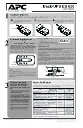
Front panel This figure shows the front panel of the 5 <strong>Port</strong> <strong>10Base</strong>-T <strong>Hub</strong>.<br />
The features of the front panel are described in the paragraphs<br />
that follow.<br />
<strong>APC</strong><br />
Communications<br />
Compatibility<br />
Number<br />
2<br />
15<br />
<strong>APC</strong> Communications<br />
Compatibility Number<br />
Col<br />
www.apcc.com<br />
Collision LED<br />
Station ports<br />
Link/Traffic LED Partition LED<br />
Figure 1: Front Panel and Connector Detail<br />
Uplink port<br />
Power LED<br />
Link/Traffic<br />
Partition<br />
1X 2X 3X 4X Uplink<br />
Smart Slot<br />
AP9615 5 <strong>Port</strong> <strong>10Base</strong>-T <strong>Hub</strong><br />
The <strong>APC</strong> Communications Compatibility Number (CCN),<br />
which appears on the upper left corner of the front panel,<br />
refers to the ability of an accessory to work with other <strong>APC</strong><br />
products. (The CCN for your hub may be different from the<br />
example shown in Figure 1.) In general, we strive to make all<br />
<strong>APC</strong> products compatible with one another; however, if you<br />
want specific information on the compatibility of the 5 <strong>Port</strong><br />
<strong>10Base</strong>-T <strong>Hub</strong> with <strong>APC</strong> UPSs and accessories, visit the<br />
<strong>APC</strong> support page (http://www.apcc.com/support/#kbase)<br />
and search for Communications Compatibility Number.<br />
Pwr<br />
Continued on next page
Product Description continued<br />
LEDs The LEDs provide important information concerning operation<br />
of the hub and each of its ports. Refer to the table below<br />
for a description of the conditions indicated by LEDs.<br />
Label Color Activity Description<br />
Pwr Green On The hub is receiving power.<br />
Col Yellow Blinking<br />
Link/<br />
Traffic<br />
Green<br />
On<br />
Partition Yellow On<br />
The network is experiencing<br />
data collisions. Note that<br />
occasional collisions are<br />
normal.<br />
The link between the port<br />
and the connected device is<br />
good.<br />
Blinking The port is receiving data.<br />
Table 1: Description of LEDs<br />
The port has been partitioned<br />
because of an excessive<br />
frequency of collisions. The<br />
partition condition will<br />
automatically clear when the<br />
connected device begins<br />
operating properly.<br />
Continued on next page<br />
3
Product Description continued<br />
Station ports The Station ports are the first 4 RJ-45 ports, which are<br />
labeled 1X–4X. The Station ports use straight-through UTP<br />
cables to connect the hub with:<br />
• Workstations or other non-hub devices that you want<br />
to include in your network.<br />
• The Uplink port of another hub in a cascading configuration.<br />
Note: A Station port acts as an Uplink port when it is used<br />
with a crossover cable.<br />
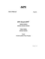
Uplink port The Uplink port is normally used in either of the following<br />
ways, as shown in Figure 2.<br />
Communication<br />
cables<br />
4<br />
➊ ➋<br />
To<br />
Corporate LAN<br />
1X 2X 3X 4X Uplink<br />
straight-through cable<br />
crossover cable<br />
Figure 2: Dual Use of the Uplink <strong>Port</strong><br />
1X 2X 3X 4X Uplink<br />
Connected in cascade with a Station port of another<br />
hub or switching device, using a straight-through<br />
cable.<br />
š Connected to a workstation or other non-hub device,<br />
using a crossover cable.<br />
The hub requires a category 3, 4, or 5 UTP <strong>10Base</strong>-T communication<br />
cable for each device to be attached.
Installing the <strong>Hub</strong><br />
Warning Do not operate the 5 <strong>Port</strong> <strong>10Base</strong>-T <strong>Hub</strong> where conditions<br />
are outside the limits listed in “Product Specifications” on<br />
page 14.<br />
Installing on<br />
critical systems<br />
Installation<br />
procedure<br />
The installation procedure that follows may involve shutting<br />
off power from the UPS. However, if your setup<br />
requires maintaining power to connected equipment<br />
throughout installation, visit the support page on our Website<br />
(http://www.apcc.com/support/#kbase) and follow the<br />
appropriate procedure in Installation Instructions for <strong>APC</strong><br />
Management Accessories on Critical Systems.<br />
To install the 5 <strong>Port</strong> <strong>10Base</strong>-T <strong>Hub</strong>, perform the following<br />
steps in the order given.<br />
Note: The Smart-UPS, Matrix-UPS, Symetra Power Array,<br />
Smart-UPS DP, and Triple Chassis for Silcon require<br />
different procedures to turn off the UPS or device that<br />
will host the hub.<br />
1 To turn off the UPS or device that will host the hub,<br />
follow the appropriate procedure listed below:<br />
Smart-UPS ®<br />
a Shut down and power off the connected equipment.<br />
b Press and hold the UPS’s Power Off button<br />
until you hear a click or until the UPS’s power<br />
LED extinguishes.<br />
c Unplug the UPS from the AC power outlet.<br />
d Press and hold the UPS’s Power Off button<br />
until you hear a click (hold for at least 5 seconds).<br />
Continued on next page<br />
5
Installing the <strong>Hub</strong> continued<br />
Installation<br />
procedure,<br />
continued<br />
6<br />
Matrix-UPS <br />
a Shut down and power off the connected<br />
equipment.<br />
b Turn off the circuit breaker on the bottom left<br />
side on the back panel of the UPS.<br />
Symmetra Power Array <br />
a Shut down and power off the connected<br />
equipment.<br />
b Turn off the System Enable switch on the<br />
bottom left side on the back panel of the UPS.<br />
Smart-UPS ® DP<br />
a Shut down and power off the connected<br />
equipment.<br />
b Turn off the ON/OFF switch on the front<br />
panel.<br />
Triple Chassis for Silcon DP300E Series UPSs<br />
a Shut down and power off the connected equipment.<br />
b If present, unplug the Triple Chassis’s power<br />
supply from the AC power outlet.<br />
c Disconnect the cable attached to the To UPS<br />
port on the Triple Chassis.<br />
2 Unpack the 5 <strong>Port</strong> <strong>10Base</strong>-T <strong>Hub</strong>. The shipping<br />
materials are recyclable. Please save, reuse, or dispose<br />
of them appropriately.<br />
Handle the 5 <strong>Port</strong> <strong>10Base</strong>-T <strong>Hub</strong> by the front<br />
panel. Do not touch the exposed printed circuit<br />
board or components. Touching the<br />
circuit board or components may result in<br />
damage to the hub.<br />
Continued on next page
Installing the <strong>Hub</strong> continued<br />
Installation<br />
procedure,<br />
continued<br />
.<br />
3 Use a #2 Phillips head screwdriver to remove the 2<br />
screws fastening the SmartSlot cover plate to the<br />
back panel of the UPS or triple chassis. Keep the<br />
screws for Step 5 below. Save the SmartSlot cover<br />
plate for future use (e.g. shipping the UPS).<br />
4 Orient the hub to fit into the SmartSlot. Slide the hub<br />
all the way into the slot until its front panel is flush<br />
with the back panel of the UPS or triple chassis.<br />
Observe the correct orientation as shown in Figure 3.<br />
Note that the sides of the circuit board align with the<br />
card guides of the SmartSlot.<br />
Note: While it is not possible to install the hub<br />
upside down, it is possible to damage the<br />
unit in the attempt to do so.<br />
Figure 3: Orient the hub to fit into the SmartSlot.<br />
Continued on next page<br />
7
Installing the <strong>Hub</strong> continued<br />
Installation<br />
procedure,<br />
continued<br />
8<br />
5 Secure the hub with the screws removed in Step 3.<br />
6 Using straight-through UTP cables, connect the Station<br />
ports (1X–4X, in any order) to each workstation’s<br />
<strong>10Base</strong>-T port or to the Uplink port of a hub to<br />
be connected in cascade.(See Figure 2 on page 4.)<br />
7 Connect the Uplink port, if applicable:<br />
• If connecting to another hub:<br />
– Use a straight-through cable to connect to a Station<br />
port. (See Figure 2 on page 4.)<br />
– Use a crossover cable to connect to the Uplink<br />
port. (See Figure 4 on page 10.)<br />
• If connecting the Uplink port to a workstation or<br />
other non-hub device:<br />
– Use a crossover cable. (See Figure 2 on page 4.)<br />
8 Turn on the UPS or device that now houses the hub.<br />
To turn on the UPS or device, follow the appropriate<br />
procedure listed below:<br />
Smart-UPS<br />
a Plug the UPS back into the AC power outlet.<br />
b Press and hold the Power On button until you<br />
hear a click and beep or until the power LED<br />
illuminates.<br />
c Power on the connected equipment.<br />
Matrix-UPS<br />
a Turn on the circuit breaker on the bottom left<br />
side on the back panel of the UPS.<br />
b Turn on the UPS via the front panel.<br />
c Power on the connected equipment.<br />
Continued on next page
Installing the <strong>Hub</strong> continued<br />
Installation<br />
procedure,<br />
continued<br />
Symmetra Power Array<br />
a Turn on the System Enable switch on the<br />
bottom left side on the back panel of the UPS.<br />
b Turn on the UPS via the PowerView display.<br />
c Power on the connected equipment.<br />
Smart-UPS DP<br />
a Turn on the ON/OFF switch on the front<br />
panel.<br />
b Power on the connected equipment.<br />
Triple Chassis for Silcon DP300E Series UPSs<br />
a Attach the cable to the To UPS port on the Triple<br />
Chassis.<br />
b If applicable, plug the Triple Chassis’s power<br />
supply into the AC power outlet.<br />
c Power on the connected equipment.<br />
Continued on next page<br />
9
Installing the <strong>Hub</strong> continued<br />
Maximum<br />
configuration<br />
10<br />
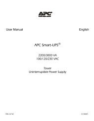
Using a star configuration, you can cascade up to ten 5 <strong>Port</strong><br />
<strong>10Base</strong>-T hubs together to provide network connections for<br />
as many as 32 stations, as shown below in Figure 4. Note<br />
the use of a crossover cable to connect the Uplink ports of<br />
the 2 central hubs.<br />
Figure 4: Cascading <strong>Hub</strong>s in a Star Configuration
Removing the <strong>Hub</strong><br />
Removal<br />
procedure<br />
To remove the 5 <strong>Port</strong> <strong>10Base</strong>-T <strong>Hub</strong>, perform the following<br />
steps in the order given.<br />
1 Disconnect all cables from the hub.<br />
2 Turn off the UPS or device that houses the hub. (For<br />
detailed instructions, see “Installation procedure” on<br />
page 5.)<br />
3 Use a #2 Phillips head screwdriver to remove the 2<br />
screws fastening the hub to the UPS or triple chassis.<br />
Keep the screws for Step 6 below.<br />
4 Carefully grasp the sides of the hub’s front panel and<br />
gently pull the hub from the SmartSlot.<br />
Handle the 5 <strong>Port</strong> <strong>10Base</strong>-T <strong>Hub</strong> by the front<br />
panel. Do not touch the exposed printed circuit<br />
board or components. Touching the<br />
circuit board or components may result in<br />
damage to the hub.<br />
5 Place the hub into its original packaging or other<br />
static-safe material.<br />
6 Replace the SmartSlot coverplate (removed during<br />
installation of the hub) with the screws removed in<br />
Step 3.<br />
11
Troubleshooting<br />
Troubleshooting<br />
suggestions<br />
12<br />
Table 2 provides suggestions for troubleshooting your hub.<br />
LED Action Cause Solution<br />
Col Blinking<br />
Col<br />
Link/<br />
Traffic<br />
Blinking<br />
excessively<br />
Off<br />
(even with<br />
a cable<br />
attached)<br />
Normal data<br />
collisions on the<br />
network.<br />
Data collisions<br />
are occurring<br />
because of a<br />
high volume of<br />
traffic on the<br />
network.<br />
Cables used to<br />
connect to the<br />
network are<br />
defective or of<br />
the wrong type.<br />
Successful link<br />
is not being<br />
detected by the<br />
port.<br />
Table 2: Suggestions for Troubleshooting<br />
No action is necessary.<br />
Make sure connected<br />
devices are not<br />
operating in fullduplex<br />
mode; they<br />
must operate in halfduplex<br />
mode.<br />
Segment the network<br />
with an Ethernet<br />
switch.<br />
Verify that the cable is<br />
of the correct type. See<br />
“Communication<br />
cables” on page4 for<br />
more information.<br />
Verify that the hub and<br />
the connected device<br />
are powered.<br />
Verify that the cable is<br />
of the correct type. See<br />
“Communication<br />
cables” on page4 for<br />
more information.<br />
Inspect cables for<br />
damage, cable pairs to<br />
see if they are wired<br />
correctly, and<br />
connectors to see if<br />
they are loose.<br />
Continued on next page
Troubleshooting continued<br />
Troubleshooting<br />
suggestions,<br />
continued<br />
LED Action Cause Solution<br />
Partition On<br />
32 consecutive<br />
collisions have<br />
caused the port<br />
to partition.<br />
Table 2: Suggestions for Troubleshooting, continued<br />
Check that the correct<br />
cable is in use and<br />
verify that the<br />
connected equipment<br />
is set to operate at 10<br />
Mbit and half-duplex<br />
mode.<br />
As collisions reduce,<br />
the port reconnects<br />
and the Partition<br />
LED turns off.<br />
13
Specifications<br />
Product<br />
specifications<br />
14<br />
The following table shows the product specifications for the<br />
5 <strong>Port</strong> <strong>10Base</strong>-T <strong>Hub</strong>.<br />
Item Specification<br />
Power<br />
Input voltage range: 18–30 VDC<br />
Maximum current draw:<br />
Physical<br />
45 mA<br />
Size (H × W × D): 1.46 × 4.75 × 4.30 in<br />
(3.7 × 12.1 × 10.9 cm)<br />
Weight: 0.25 lb (0.11 kg)<br />
Shipping weight:<br />
Environmental<br />
0.65 lb (0.30 kg)<br />
Elevation (above MSL):<br />
Operating<br />
Storage<br />
0 to 10,000 ft (0 to 3000 m)<br />
0 to 50,000 ft (0 to 15 000 m)<br />
Temperature:<br />
Operating<br />
Storage<br />
32 to 122°F (0 to 50°C)<br />
5 to 158°F (-15 to 70°C)<br />
Relative humidity:<br />
Operating<br />
Storage<br />
0 to 95%, non-condensing<br />
0 to 95%, non-condensing<br />
Approvals/Standards<br />
FCC, Part 15, Class B<br />
EN 55 022 (CISPR 22), Class B<br />
VCCI Class 2<br />
IEC 1000-4-2, 3, 4<br />
CE<br />
C-Tick<br />
IEEE 802.3 <strong>10Base</strong>-T<br />
<strong>Port</strong> Configuration: Station <strong>Port</strong>s are MDI-X, Uplink port is MDI<br />
Table 3: Product Specifications
Warranty Information<br />
Limited<br />
warranty<br />
Warranty<br />
registration<br />
Warranty<br />
limitations<br />
American Power Conversion (<strong>APC</strong>) warrants the 5 <strong>Port</strong><br />
<strong>10Base</strong>-T <strong>Hub</strong> to be free from defects in materials and workmanship<br />
for a period of 2 years from the date of purchase. Its<br />
obligation under this warranty is limited to repairing or<br />
replacing, at its own sole option, any such defective products.This<br />
warranty does not apply to equipment which has<br />
been damaged by accident, negligence, or misapplication or<br />
has been altered or modified in any way. This warranty<br />
applies only to the original purchaser.<br />
To register your product with <strong>APC</strong>, visit our Warranty Registration<br />
Web page. (http://www.apcc.com/support/warranty)<br />
Except as provided herein, American Power Conversion<br />
makes no warranties, express or implied, including warranties<br />
of merchantability and fitness for a particular purpose.<br />
Some jurisdictions do not permit limitation or exclusion of<br />
implied warranties; therefore, the aforesaid limitation(s) or<br />
exclusion(s) may not apply to the purchaser.<br />
Except as provided above, in no event will <strong>APC</strong> be liable for<br />
direct, indirect, special, incidental, or consequential damages<br />
arising out of the use of this product, even if advised of the<br />
possibility of such damage.<br />
Specifically, <strong>APC</strong> is not liable for any costs, such as lost<br />
profits or revenue, loss of equipment, loss of use of equipment,<br />
loss of software, loss of data, costs of substitutes,<br />
claims by third parties, or otherwise. This warranty gives<br />
you specific legal rights and you may also have other rights<br />
which vary from state to state.<br />
15
Warranty Information continued<br />
Obtaining<br />
service<br />
16<br />
To obtain service for your 5 <strong>Port</strong> <strong>10Base</strong>-T <strong>Hub</strong>, follow this<br />
procedure:<br />
1 Note the serial number and date of purchase of the<br />
hub. (The serial number is located on the top, interior<br />
surface of the hub’s front panel.)<br />
2 Contact <strong>APC</strong> Customer Support at the phone number<br />
or address on the back cover of this manual.<br />
3 Be prepared to provide a description of the problem.<br />
A technician will help solve the problem over the<br />
phone, if possible, or will give you a return material<br />
authorization (RMA) number.<br />
4 If the hub is under warranty, repair or replacement is<br />
free of charge. If the warranty has expired, there will<br />
be a nominal charge for repair or replacement.<br />
5 Pack the hub carefully in its original packaging, if<br />
possible. Do not use polystyrene beads for packing.<br />
Damage sustained in transit is not covered under the<br />
warranty. Enclose a letter in the package with your<br />
name, address, RMA number, a copy of the sales<br />
receipt, daytime phone number, and check (if applicable).<br />
6 Mark the RMA number clearly on the outside of the<br />
shipping carton. The service center will not accept<br />
any materials without this marking.<br />
7 Return the hub by insured, prepaid carrier to the<br />
address given to you by <strong>APC</strong> Customer Support.
Declaration of Conformity<br />
Application of Council<br />
Directives<br />
Standards to Which<br />
Conformity is<br />
Declared<br />
Manufacturer’s Name<br />
and Address<br />
Importer’s Name and<br />
Address<br />
89/336/EEC<br />
EN55022: 1995, Class B<br />
EN50082-1: 1992, including:<br />
IEC 1000-4-2: 1995<br />
IEC 1000-4-3: 1995<br />
IEC 1000-4-4: 1995<br />
FCC Part 15, Class B<br />
VCCI, Class 2<br />
American Power Conversion<br />
132 Fairgrounds Road<br />
West Kingston, Rhode Island 02892<br />
USA<br />
–or–<br />
American Power Conversion (A.P.C.) b.v.<br />
Ballybritt Business Park<br />
Galway, Ireland<br />
American Power Conversion (A.P.C.) b.v.<br />
Ballybritt Business Park<br />
Galway, Ireland<br />
Type of Equipment UPS Accessory Equipment<br />
Model Numbers AP9615<br />
Serial Numbers RA9901D00000–RA0001D99999<br />
Years of Manufacture 1999, 2000<br />
Table 4:<br />
We, the undersigned, hereby declare that the equipment specified above<br />
conforms to the above directives.<br />
St. Louis, MO, USA June 24, 1999<br />
Place<br />
Date<br />
Galway, Ireland June 24, 1999<br />
Place<br />
Date<br />
Ted Eckert<br />
Regulatory Compliance Engineer<br />
Ray Ballard<br />
General Manager, Galway
Toll-free Customer Support:<br />
U. S. & Canada 1-800-800-4272<br />
Austria 0660 6480<br />
Belgium 0800 15063<br />
Czech Republic 0 800 102063<br />
Denmark 800 18 153<br />
Finland 9800 13 374<br />
France 0 800 906 483<br />
Germany 01300818907<br />
Holland 0800 0224655<br />
Hungary 00800 12221<br />
Ireland 1 800 702000 x 2045<br />
Israel 177 353 2206<br />
Italy 1678 74731<br />
Japan 0120-80-60-90<br />
Luxembourg 0800 2091<br />
Norway 800 11 632<br />
Poland 00800 353 1202<br />
<strong>Port</strong>ugal 050 553182<br />
South Africa 0800 994206<br />
Spain 900 95 35 33<br />
Sweden 020 795 419<br />
Switzerland 0800 556177<br />
Turkey 0800 35390275<br />
U. K. 0800 132990<br />
Areas without toll-free numbers:<br />
+1 401 789 5735 (USA) or<br />
+353 91 702020 (Ireland)<br />
+7095 916 7166 (Russia)<br />
Serial number:<br />
www.apcc.com<br />
E-mail Customer Support:<br />
Australia anztech@apcc.com<br />
Europe apceurtech@apcc.com<br />
India isbtech@apcc.com<br />
Japan jsupport@apcc.com<br />
Latin America apctchla@apcc.com<br />
SE Asia asetech@apcc.com<br />
On-line Customer Support:<br />
U.S. & Canada http://support.apcc.com/<br />
Addresses:<br />
American Power Conversion Corporation<br />
132 Fairgrounds Road<br />
P. O. Box 278<br />
West Kingston, Rhode Island 02892<br />
USA<br />
<strong>APC</strong> Ireland<br />
(A. P. C.) b. v.<br />
Ballybritt Business Park<br />
Galway<br />
Ireland<br />
<strong>APC</strong> Japan<br />
BR Gotanda 7 th Floor<br />
2-30-4 Nishi-gotanda,<br />
Shinagawa-ku<br />
Tokyo 141 Japan<br />
<strong>APC</strong> Europe<br />
143 Bis Avenue de Verdun<br />
92442 Issy-les-Moulineaux Cedex<br />
France<br />
Entire contents copyright © 1999 American Power Conversion. All rights reserved.<br />
Reproduction in whole or in part without permission is prohibited.<br />
All trademarks are the property of American Power Conversion.<br />
990-0324 7/99