The Global Magazine of Leica Geosystems
The Global Magazine of Leica Geosystems
The Global Magazine of Leica Geosystems

You also want an ePaper? Increase the reach of your titles
YUMPU automatically turns print PDFs into web optimized ePapers that Google loves.
60<br />
<strong>The</strong> <strong>Global</strong> <strong>Magazine</strong> <strong>of</strong> <strong>Leica</strong> <strong>Geosystems</strong>
Dear Readers,<br />
A new edition <strong>of</strong> the “Reporter” lies on my desk,<br />
ready for printing. At such moments, the thought<br />
crosses my mind how exciting the business we all<br />
work in is. In close cooperation with our customers,<br />
the editorial team manages to present the whole<br />
range <strong>of</strong> measurement technologies – geomatics,<br />
engineering, construction, machine control, geographic<br />
information systems, and high definition<br />
scanning – by describing fascinating projects. <strong>The</strong>se<br />
projects, realized by our customers, are very diverse:<br />
for example the Arabian Canal in Dubai’s desert, the<br />
Gotthard base tunnel in Switzerland, an American oil<br />
refinery, or the capturing and processing <strong>of</strong> digital<br />
aerial images in the UK.<br />
Infrastructure projects are an important factor in<br />
helping to ease the economic crisis that dominates<br />
the news as well as our everyday conversations at<br />
the moment. This is also demonstrated through the<br />
economic stimulus programmes launched by governments<br />
all around the world. Sustainability, stability,<br />
and reliability are becoming increasingly important.<br />
At <strong>Leica</strong> <strong>Geosystems</strong>, we combine these values with a<br />
deep understanding <strong>of</strong> users’ needs – accuracy, productivity,<br />
and efficiency. Transferring these values<br />
and this knowledge into products and solutions, we<br />
enable our customers to stay ahead <strong>of</strong> their competitors.<br />
Thus, we not only contribute to their economic<br />
success, but also ensure that our “Reporter”-Team<br />
will have exciting projects to present in the future.<br />
Enjoy reading!<br />
Ola Rollén<br />
CEO Hexagon and <strong>Leica</strong> <strong>Geosystems</strong><br />
2 | Reporter<br />
Editorial<br />
CONTENTS<br />
03<br />
06<br />
08<br />
10<br />
12<br />
14<br />
18<br />
22<br />
23<br />
23<br />
Imprint<br />
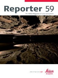
57 km long and<br />
in the right Place<br />
<strong>The</strong> City Walls <strong>of</strong> Dubrovnik<br />
Project Savings at Deer Park<br />
Arabian Canal:<br />
A Miracle in the Making<br />
Laser Land Levelling<br />
Refined Dimensions<br />
A new Level <strong>of</strong> Precision<br />
<strong>Leica</strong> TS30: Pride in Accuracy<br />
NRS TruStory:<br />
First Prize goes to Latvia<br />
<strong>Leica</strong> <strong>Geosystems</strong> Technologies:<br />
«Singapore Quality Class»<br />
Reporter: Customer <strong>Magazine</strong> <strong>of</strong> <strong>Leica</strong> <strong>Geosystems</strong><br />
Published by: <strong>Leica</strong> <strong>Geosystems</strong> AG, CH-9435 Heerbrugg<br />
Editorial Office: <strong>Leica</strong> <strong>Geosystems</strong> AG,<br />
9435 Heerbrugg, Switzerland, Phone +41 71 727 34 08,<br />
reporter@leica-geosystems.com<br />
Contents responsible: Alessandra Doëll<br />
(Director Communications)<br />
Editor: Agnes Zeiner<br />
Publication details: <strong>The</strong> Reporter is published in English,<br />
German, French, and Spanish, twice a year.<br />
Reprints and translations, including excerpts, are subject to<br />
the editor’s prior permission in writing.<br />
© <strong>Leica</strong> <strong>Geosystems</strong> AG, Heerbrugg (Switzerland),<br />
May 2009. Printed in Switzerland<br />
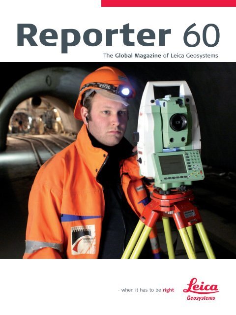
Cover: BSF Swissphoto AG: Employee Reto Bardill<br />
surveying in the Gotthard base tunnel
57 km long and<br />
in the right Place<br />
by Agnes Zeiner, Pictures: BSF Swissphoto AG<br />
With the modernization <strong>of</strong> its railway infrastructure,<br />
Switzerland seeks to connect to the<br />
European high-speed train network and achieve<br />
a reduction in the amount <strong>of</strong> the transit traffic<br />
on its roads. One <strong>of</strong> the key projects is the “Alp-<br />
Transit Gotthard”, at the heart <strong>of</strong> which is the<br />
Gotthard Base Tunnel: A 57-km-long twin-tube<br />
railway tunnel and the longest tunnel in Europe.<br />
A challenge to the surveyors – under and on the<br />
mountain.<br />
Switzerland lies at the centre <strong>of</strong> Europe and the Alps.<br />
This compact country <strong>of</strong> blooming alpine pastures<br />
and the classic children's story <strong>of</strong> Heidi, is the same<br />
country that has a major share <strong>of</strong> European traffic<br />
rolling through it north to south – and back again.<br />
Traffic flows have increased continuously over the<br />
decades, as more and more people and goods cross<br />
the Alps in both directions. One <strong>of</strong> the most important<br />
transit routes in Europe passes over the 2’108 m<br />
high St. Gotthard Pass.<br />
Modern low-level rail link<br />
with speeds <strong>of</strong> up to 250 km/h<br />
<strong>The</strong> Gotthard Rail Tunnel was built more than 125<br />
years ago. Otto Gelpke and Carl Koppe, two surveyors<br />
working independently <strong>of</strong> one another, each<br />
created a triangulation network, which – checked<br />
by comparison <strong>of</strong> the two meshes – was to form<br />
the basis for all the later surveys. In 1880 when the<br />
breakthrough <strong>of</strong> the 15 km long Gotthard Rail Tunnel<br />
took place, the deviation <strong>of</strong> the two headings was<br />
only 30 cm – an incredible success for the surveyors<br />
involved.<br />
>><br />
<strong>The</strong> <strong>Global</strong> <strong>Magazine</strong> <strong>of</strong> <strong>Leica</strong> <strong>Geosystems</strong> | 3
4 | Reporter<br />
Gotthard Base Tunnel<br />
Length: 57 km<br />
Scheduled completion: End <strong>of</strong> 2017<br />
Construction costs (2008):<br />
6.43 billion euro (8.62 billion US$)<br />
Construction costs (2008) including Ceneri<br />
Base Tunnel: 7.76 billion euro (10.41 billion US$)<br />
Surveying:<br />
Consortium VI-GBT c/o Grünenfelder und Partner AG<br />
and ARGE LOS349 c/o BSF Swissphoto AG,<br />
www.bsf-swissphoto.ch<br />
This would have been way outside the accuracy <strong>of</strong><br />
10 cm horizontally and 5 cm vertically required <strong>of</strong> the<br />
engineers working for the surveying consortium VI-<br />
GBT today, because the new Gotthard Base Tunnel<br />
is designed for a modern low-level, high-speed railway.<br />
<strong>The</strong> highest point on the route is only 550 m<br />
above sea level and the maximum gradient is limited<br />
to 0.8 percent. This means that from the end<br />
<strong>of</strong> 2017 (scheduled date), high-speed trains with<br />
people, goods, and vehicles on board will be carried<br />
safely through the Alps at speeds <strong>of</strong> up to 250 km/h.<br />
Perfect alignment <strong>of</strong> the track is essential for this to<br />
happen.<br />
<strong>The</strong> hole in the right place<br />
Ensuring that the alignment complies with these<br />
requirements is the task <strong>of</strong> Ivo Schätti and his team<br />
from Grünenfelder & Partner AG, the lead engineering<br />
consultancy in the surveying consortium. As the<br />
client's surveying engineers, they are responsible for<br />
maintaining the correct position, height, and direction<br />
as the mega-tunnel heading advances. “You<br />
could say we have to make sure the hole is in the<br />
right place,” grins Schätti during our visit to his <strong>of</strong>fice<br />
in Domat-Ems, a small town near the Gotthard section<br />
<strong>of</strong> the works. A map on the wall showing the<br />
whole project gives rise to the suspicion that it might<br />
be somewhat more difficult than that. “<strong>The</strong> special<br />
aspects <strong>of</strong> this project naturally include its length,<br />
Instruments used for tunnel surveying:<br />
Precision total station <strong>Leica</strong> TCA2003<br />
Digital level <strong>Leica</strong> DNA03<br />
Nadirlot NL<br />
Instruments used for monitoring :<br />
Precision total station <strong>Leica</strong> TCA2003<br />
Monitoring s<strong>of</strong>tware <strong>Leica</strong> GeoMoS<br />
<strong>Leica</strong> GPS System 500<br />
Monitoring the Nalps dam wall<br />
the five entry points out <strong>of</strong> which we work, and <strong>of</strong><br />
course the required accuracy,” he adds.<br />
Great effort for control surveys<br />
<strong>The</strong> mega-tunnel is being built from five places at<br />
once – the two portals at Erstfeld (north) and Bodio<br />
(south), and intermediate headings at Amsteg, Sedrun,<br />
and Faido. <strong>The</strong> basic primary network was created<br />
in 1995 and was completely resurveyed ten years<br />
later. “In 1995 the use <strong>of</strong> GPS was still relatively new,<br />
but our measurements confirmed that the points<br />
were stable,” declared Schätti.<br />
One <strong>of</strong> the principal tasks <strong>of</strong> Grünenfelder & Partner<br />
AG at the moment is tunnel control. As the client's<br />
surveyors, the team can take more time for its measurements,<br />
but also work more intensely, using special<br />
instruments such as a gyrotheodolite and enjoying<br />
better working conditions than the contractor's<br />
survey teams, who continuously monitor and control<br />
the heading. <strong>The</strong>ir measurements are usually taken<br />
when the site is shut down. “This entails coming into<br />
work over Christmas and on other public holidays,”<br />
says Schätti.<br />
<strong>The</strong> checks are necessary as errors can creep in<br />
through many factors. One source <strong>of</strong> errors is temperature<br />
fluctuations: ventilation equipment distributes<br />
the relatively high temperatures uniformly
under the mountain specifically for the surveying<br />
operations and the survey concept was designed to<br />
suit these conditions. “When you are underground<br />
you do not know how gravity is behaving in response<br />
to different rock densities – these errors would be<br />
transferred immediately into our measurements.<br />
<strong>The</strong>refore we refer back to survey models based<br />
on measurements we have taken on the surface,”<br />
explains Ivo Schätti.<br />
Dam wall monitoring on the surface<br />
While the tunnel boring machines are continuously<br />
eating their way through the base <strong>of</strong> the Gotthard<br />
massif, other measurements are being taken on<br />
the surface. Some parts <strong>of</strong> the tunnel pass directly<br />
under three water storage reservoirs, and although<br />
the tunnel lies very far underground, the effects on<br />
the surface should not be underestimated. “A tunnel<br />
affects the normal flows and pressures <strong>of</strong> ground<br />
water. <strong>The</strong> pressure loss due to the removal <strong>of</strong> the<br />
water in the rock could cause the mountain literally to<br />
cave in,” explains Ivo Schätti. A change <strong>of</strong> pressure like<br />
this could have disastrous consequences for the dam<br />
walls <strong>of</strong> the three reservoirs at Curnera, Nalps, and<br />
Santa Maria in the Upper Rhine Valley – and the tunnel<br />
driving would have to be stopped immediately.<br />
For this reason BSF Swissphoto AG, the lead surveying<br />
consultant <strong>of</strong> the ARGE Los349 consortium, is<br />
monitoring the valley walls near the dam walls and<br />
the area in front <strong>of</strong> them. Measuring points were<br />
fixed directly on the rock or were set on up to 3metre-high<br />
concrete pillars which the team constructed<br />
themselves. No easy task, given that all the<br />
materials had to be flown in by helicopter and the<br />
prisms fixed on to vertical rock faces. Highly precise<br />
<strong>Leica</strong> TCA2003 total stations, protected against<br />
the weather in small enclosures and controlled using<br />
<strong>Leica</strong> GeoMoS, measure the movements <strong>of</strong> the prisms<br />
and transmit the data to monitoring s<strong>of</strong>tware developed<br />
in-house. “<strong>The</strong> instruments have been operating<br />
since 2000 and continue to work perfectly,” he<br />
adds on behalf <strong>of</strong> a satisfied BSF Swissphoto. Spot<br />
level surveys were carried out at particularly critical<br />
areas along the route using a <strong>Leica</strong> GPS System 500<br />
to determine the settlement <strong>of</strong> individual points.<br />
<strong>The</strong> long, hard winters in the Swiss mountains make<br />
the team's job even more difficult: “In places the<br />
snow depths are huge, some points in avalanche<br />
areas are <strong>of</strong>f limits for the whole <strong>of</strong> the winter, and<br />
<strong>of</strong>ten ice forms on the prisms and can remain there<br />
all day. In spite <strong>of</strong> all this we have been able to reach<br />
90 percent <strong>of</strong> our points, even in the winter,” concludes<br />
Ivo Schätti.<br />
<strong>The</strong> <strong>Global</strong> <strong>Magazine</strong> <strong>of</strong> <strong>Leica</strong> <strong>Geosystems</strong> | 5
6 | Reporter<br />
<strong>The</strong> City Walls<br />
<strong>of</strong> Dubrovnik<br />
by Miljenko Žabcic; Picture: Gerald Loacker<br />
Geographica d.o.o. recently completed a major<br />
project which included scanning and comprehensive<br />
documentation <strong>of</strong> the almost 2 km long<br />
city walls <strong>of</strong> Dubrovnik in the very south <strong>of</strong> Croatia<br />
for the “Society <strong>of</strong> Friends <strong>of</strong> Dubrovnik's<br />
Cultural Heritage”, a group <strong>of</strong> engaged citizens.<br />
<strong>The</strong> medieval city, nicknamed “the Pearl <strong>of</strong> the<br />
Adriatic”, is on the UNESCO list <strong>of</strong> World Heritage<br />
Sites. Purpose <strong>of</strong> the four year project was<br />
to fully document the current state <strong>of</strong> the city<br />
walls and fortresses for future improvements<br />
and in order to preserve their current state for<br />
upcoming generations.<br />
<strong>The</strong> “Society <strong>of</strong> Friends <strong>of</strong> Dubrovnik's Cultural<br />
Heritage” (Društvo prijatelja dubrovacke starine)<br />
approached Geographica d.o.o. in 2004, as<br />
Dubrovnik’s city walls hadn't ever been completely<br />
documented before. 3D laser scanning was selected<br />
as the best method. <strong>The</strong> documentation included<br />
scanning, modeling, and drawing and will be used<br />
for multiple purposes such as everyday maintenance,<br />
legal requirements, interior design for functionality<br />
improvements, cost estimate calculations for various<br />
work, study <strong>of</strong> the object in terms <strong>of</strong> its origin, and<br />
building stages.<br />
<strong>The</strong> town fortifications, ramparts, and towers outside<br />
the walls were built, reinforced, and reconstructed<br />
in the period from the 12th to the second<br />
half <strong>of</strong> the 17th century. A number <strong>of</strong> engineers were<br />
involved in these works – well known names such as<br />
Nicifor Ranjina in 1319, Michelozzo di Bartholomeo in<br />
1461–1464, Juraj Dalmatinac or George the Dalmatian<br />
in 1465–1466, Paskoje Milicevic in 1466–1516,<br />
and Antonio Ferramolino in 1538.<br />
<strong>The</strong> main wall is 1’940 m long (following the ring-corridor),<br />
4–6 m wide on the mainland side and between<br />
1.5 and 5 m wide on the sea side. It is up to 25 m high<br />
in parts. <strong>The</strong> wall was reinforced by three circular and<br />
14 quadrangular towers, five bastions (bulwarks),<br />
two angular fortifications, and a large fortress called<br />
Sveti Ivan (St. John). Among the towers, the most<br />
monumental is the circular tower <strong>of</strong> Minceta, on the<br />
north-western corner <strong>of</strong> the ramparts. <strong>The</strong> reinforcement,<br />
along the main wall on the mainland side,<br />
includes one larger and nine smaller semicircular bastions,<br />
and the casemate fortress Bokar, the oldest<br />
preserved fortress <strong>of</strong> its kind in Europe.<br />
Very dense scan data<br />
Since one <strong>of</strong> the products to be achieved with the<br />
scan data were plane drawings <strong>of</strong> the current state<br />
<strong>of</strong> the walls, including drawings <strong>of</strong> the wall’s struc-
ture, scans had to be very dense. <strong>The</strong>refore all the<br />
walls ware scanned with a resolution <strong>of</strong> under 1 cm,<br />
usually around 5–8 mm, depending <strong>of</strong> the shape <strong>of</strong><br />
the stones. Only the interiors <strong>of</strong> the fortresses were<br />
scanned with a resolution <strong>of</strong> 2.5 cm. <strong>The</strong> scan data is<br />
a very important part <strong>of</strong> the final product because it<br />
will be used in the future for precise measurements<br />
in the process <strong>of</strong> preservation.<br />
3D model as simplified representation<br />
A 3D model was created as a simplified representation<br />
<strong>of</strong> the walls and fortresses but it contained all<br />
main construction elements <strong>of</strong> the walls. It is used<br />
for general planning in various projects, fast overview<br />
<strong>of</strong> parts <strong>of</strong> interest, calculations <strong>of</strong> quantity and<br />
expenses in preservation works and presentations.<br />
<strong>The</strong> model was created in two steps. <strong>The</strong> first step<br />
was edge extraction, done with <strong>Leica</strong> Cyclone S<strong>of</strong>tware<br />
by converting the edges <strong>of</strong> scan data into lines<br />
and polylines. <strong>The</strong> second step was the generation<br />
<strong>of</strong> surfaces from the extracted edges. Surfaces were<br />
generated in a CAD environment to ensure the whole<br />
model is suitable for a wide range <strong>of</strong> applications<br />
and users.<br />
Plane drawings as documentation<br />
<strong>of</strong> the current state<br />
Generating the plane drawings was the most<br />
demanding and time-consuming part <strong>of</strong> the project.<br />
City Walls <strong>of</strong> Dubrovnik<br />
Total perimeter (including both sides<br />
<strong>of</strong> the walls): 4’300 m<br />
Total scanned area: 120’000 m²<br />
Scanning time: 240 days (1 scanner, 2 operators)<br />
Products: <strong>Leica</strong> HDS2500, <strong>Leica</strong> ScanStation<br />
Total project time: 4 years with two persons<br />
in the field and three persons in the <strong>of</strong>fice<br />
According to Croatian laws <strong>of</strong> preservation <strong>of</strong> cultural<br />
heritage this documentation has to be prepared for<br />
plot with a scale factor <strong>of</strong> 1 : 50 and must include<br />
ground views, horizontal, and vertical sections and<br />
facade (elevation) views with stone structure. Every<br />
drawing has to be dimensioned with plane and height<br />
dimensions.<br />
Drawings were created in a CAD environment using<br />
<strong>Leica</strong> CloudWorks for AutoCAD. <strong>The</strong>se drawings are<br />
very detailed and contain all the segments <strong>of</strong> the<br />
walls including drawings <strong>of</strong> every individual stone.<br />
<strong>The</strong> number <strong>of</strong> required drawings was not defined at<br />
the project beginning. <strong>The</strong>re have to be enough to<br />
represent every part <strong>of</strong> the walls and every segment<br />
<strong>of</strong> its construction. In case <strong>of</strong> disaster it must be possible<br />
to completely reconstruct the walls according<br />
to this documentation. Such drawings are also used<br />
for detailed planning in preservation and restoration,<br />
studying the walls’ history and phases <strong>of</strong> building,<br />
everyday preservation works in the field, and various<br />
other tasks.<br />
About the author:<br />
Miljenko Žabcic is a surveying engineer and director<br />
<strong>of</strong> Geographica d.o.o. in Split, Croatia. Geographica<br />
d.o.o., founded in 1999, employs 12 experts covering<br />
the fields <strong>of</strong> geodesy, architecture, construction, and<br />
archaeology. <strong>The</strong> company was the first in Croatia to<br />
start using 3D laser scanning technology in 2003.<br />
<strong>The</strong> <strong>Global</strong> <strong>Magazine</strong> <strong>of</strong> <strong>Leica</strong> <strong>Geosystems</strong> | 7
8 | Reporter<br />
Project Savings<br />
at Deer Park<br />
by Stefana Vella<br />
One <strong>of</strong> Australia’s leading construction companies,<br />
Leighton Contractors, is realizing the<br />
benefits <strong>of</strong> using <strong>Leica</strong> GradeSmart and <strong>Leica</strong><br />
DigSmart machine control technology during<br />
construction <strong>of</strong> Melbourne’s $331 million,<br />
9.3 km Deer Park bypass. <strong>Leica</strong> <strong>Geosystems</strong> distributors<br />
CR Kennedy fitted several graders and<br />
excavators with the latest GNSS 3D technology<br />
to deliver higher productivity, machine utilization,<br />
and performance.<br />
<strong>The</strong> Deer Park bypass is the largest design and construction<br />
contract awarded by VicRoads and features<br />
four lanes and four major interchanges over its 9.3 km<br />
length. Scheduled to open in late 2009, the bypass<br />
will eliminate 20 intersections and is expected to<br />
reduce journeys by up to 15 minutes.<br />
Leighton Construction Manager Ray Wall chose to<br />
equip three graders (two John Deere 872 and a Caterpillar<br />
140H) with <strong>Leica</strong> GradeSmart 3D technology<br />
and to fit two subcontractor excavators with <strong>Leica</strong><br />
DigSmart 3D guidance systems. Calculating the return<br />
on investment was straightforward, Mr. Wall said:<br />
“<strong>The</strong> grader systems have basically cut out the need<br />
for two or three blokes with stringlines and pegs for<br />
each machine. And with the two excavator systems<br />
we have also been able to cut a man out because we<br />
don’t need a spotter measuring with the excavators.<br />
<strong>The</strong> systems are cheap to buy when compared to<br />
what you are saving. When you add up nine wages if<br />
you were using surveying crews you are miles ahead<br />
and over a two-year project like this that adds up to<br />
substantial wage costs. You also don’t have to water<br />
or feed them or get them out <strong>of</strong> the weather.”<br />
Compatibility with surveying equipment<br />
Deer Park bypass senior surveyor, Greg Bennett <strong>of</strong><br />
GW Bennett & Associates said <strong>Leica</strong> <strong>Geosystems</strong>’<br />
compatibility with surveyor’s equipment was a major<br />
feature. “We load the designs straight from our <strong>Leica</strong><br />
LISCAD s<strong>of</strong>tware already in the format required by<br />
the graders. With the <strong>Leica</strong> <strong>Geosystems</strong>’ system we<br />
can also load much more information onto the data<br />
card than any other system available and we can do<br />
it quicker because there are no compatibility problems.<br />
We can load 16 MB <strong>of</strong> data on one data card,<br />
but we generally break the project into two design
models <strong>of</strong> about 8 MB each. Compare that to some<br />
other systems that will only take 1 MB total – it is a<br />
massive advantage,” he said.<br />
Ray Wall added: “This gives us great flexibility with<br />
the graders because we can move them anywhere<br />
on the project – with other systems we are limited<br />
until we load new designs if a grader needs to move.”<br />
Set in automatic mode, the <strong>Leica</strong> GradeSmart 3D system<br />
precisely controls the blade to the design model<br />
loaded, moving it to the required elevation, angle,<br />
and side shift in real time – eliminating operator<br />
guesswork, multipassing, and the need for re-work.<br />
One-man operation<br />
Fitting <strong>Leica</strong> DigSmart 3D technology to two contractor’s<br />
excavators has also delivered timesavings for<br />
Leighton Contractors. “With excavators you’d generally<br />
have to peg trenches up to three times as they<br />
got closer to the design, now with <strong>Leica</strong> <strong>Geosystems</strong>’<br />
technology we start at ground level and go through<br />
in a complete cut – the operator does everything<br />
according to the instructions,” Mr. Wall said. “It is<br />
basically stake-less and with GNSS is accurate to<br />
± 30 mm so when we are pulling up batters it is prob-<br />
ably 20 percent quicker and you don’t have to wait<br />
for anyone to grade check – it becomes a one-man<br />
operation.”<br />
“Wouldn’t do it any other way”<br />
<strong>Leica</strong> DigSmart monitors the precise position <strong>of</strong> the<br />
digging bucket with the data appearing via an onboard<br />
monitor in real time allowing the operator to<br />
excavate, trench, or batter confidently. “We can have<br />
the GNSS machine cut slots in batters every 20 m<br />
and then put another excavator in there to work <strong>of</strong>f<br />
those slots,” Mr. Wall said. “<strong>The</strong> accuracy we achieve<br />
using DigSmart when digging drains and other earthworks<br />
is a lot better than having an operator trying<br />
to measure <strong>of</strong>f pegs. This is the first job where we’ve<br />
had a lot to do with the stake-less systems – I’ve<br />
seen it at EastLink [compare Reporter 57] and was<br />
impressed with it and thought we would give it a go<br />
here. Now I wouldn’t do it any other way.”<br />
About the author:<br />
Stefana Vella is Business Development Consultant and<br />
Marketing Manager for Machine Control at C.R. Kennedy<br />
& Company Pty. Ltd., <strong>Leica</strong> <strong>Geosystems</strong> Dealer<br />
in Australia.<br />
<strong>The</strong> <strong>Global</strong> <strong>Magazine</strong> <strong>of</strong> <strong>Leica</strong> <strong>Geosystems</strong> | 9
10 | Reporter<br />
Arabian Canal:<br />
A Miracle in<br />
the Making<br />
by Agnes Zeiner<br />
“Like our CEO, Saeed Ahmed Saeed, one must<br />
be visionary,” insists Dr. Nedal Al-Hanbali, Head<br />
<strong>of</strong> Corporate Geomatics Information Systems at<br />
Limitless LLC. Visionary is the way to describe<br />
the Arabian Canal, a project on which the surveyor<br />
will work for the next 15 years. In the<br />
Dubai desert, Limitless is building a 75 km long<br />
canal and waterside city where up to two million<br />
people will live and work.<br />
Nedal Al-Hanbali’s life can be defined as dedicated<br />
to establishing and building a new standard and<br />
caliber <strong>of</strong> Geomatics/GIS in the real estate industry<br />
using state-<strong>of</strong>-the-art technologies. One <strong>of</strong> his most<br />
important projects is the Arabian Canal. “At Limitless<br />
we have visionary objectives that do not remain<br />
dreams, but are actually realized. <strong>The</strong> consequences<br />
are projects as unique and innovative as the Arabian<br />
Canal. This visionary approach is the reason I joined<br />
Limitless,” explains the Geomatics/Surveying expert,<br />
former pr<strong>of</strong>essor at the Al-Balqa’ University in Jordan<br />
and researcher at the University <strong>of</strong> Calgary/Canada.<br />
Modern city in the Dubai desert<br />
This fascinating project involves construction <strong>of</strong> a<br />
75 km long canal, in the shape <strong>of</strong> a horseshoe, flowing<br />
inland from Palm Jumeirah harbor to the west to<br />
the new Dubai World Central International Airport,<br />
and east to the harbor area again. It will be approximately<br />
150 m wide and 6 m deep.
On its banks will be hills and valleys – a new topography<br />
for Dubai – and a modern, sustainable city.<br />
Supplied with water from the Gulf, Arabian Canal<br />
will have marinas, promenades, beaches, and public<br />
transport on the canal. Construction costs for the<br />
waterway – the most complex civil engineering project<br />
ever undertaken in the Middle East – are estimated<br />
at US$11 billion.<br />
For a project <strong>of</strong> this magnitude it is crucial to use<br />
resources as economically as possible. “<strong>The</strong> project<br />
involves moving large amounts <strong>of</strong> earth each day,<br />
which requires a highly efficient system,” explains<br />
Dr. Nedal. “<strong>The</strong> basis for the system is a model <strong>of</strong><br />
the terrain that is constantly kept up to date with<br />
the aid <strong>of</strong> a complex interaction between total stations,<br />
GPS/GNSS, HDS scanners, airborne digital sensor<br />
cameras with LIDAR, reference stations, and to<br />
some extent custom s<strong>of</strong>tware.”<br />
Continuous support<br />
Several <strong>Leica</strong> <strong>Geosystems</strong> instruments for static and<br />
dynamic measurements are used in this process. A<br />
high definition scanner, <strong>Leica</strong> ScanStation 2, provides<br />
point clouds <strong>of</strong> the terrain, while <strong>Leica</strong> SmartPoles<br />
are used for the surveying. A dedicated GNSS reference<br />
station network with five stations and <strong>Leica</strong><br />
GNSS Spider s<strong>of</strong>tware provide the necessary RTK<br />
correction data for the entire area. Soon a further<br />
reference station will be added.<br />
Before appointing <strong>Leica</strong> <strong>Geosystems</strong> as a supplier, a<br />
number <strong>of</strong> possible systems were put through their<br />
paces, explains Nedal Al-Hanbali. “We organized<br />
a ‘competition’ between the various providers to<br />
obtain the best possible instruments for our requirements.<br />
Important factors included speed, efficiency,<br />
accuracy, the integration <strong>of</strong> s<strong>of</strong>tware and workflows,<br />
and also the customer support and people behind<br />
these products. During this process all companies<br />
<strong>of</strong>fered their equipment for several days <strong>of</strong> testing in<br />
the Arabian Canal pilot excavation. <strong>The</strong> regional sales<br />
partner for <strong>Leica</strong> <strong>Geosystems</strong>, Geco, was very cooperative,<br />
<strong>of</strong>fering their scanner for three consecutive<br />
tests to explore all possible scanning and processing<br />
possibilities. As a result we could check on-site that<br />
the instruments – and service – met our requirements.<br />
Geco now also provides us with continuous<br />
support during the construction phase.”<br />
Limitless LLC<br />
<strong>Global</strong> Real Estate Developer<br />
Business unit <strong>of</strong> Dubai World,<br />
one <strong>of</strong> Dubai's leading business groups<br />
Set up in July 2005<br />
CEO: Saeed Ahmed Saeed<br />
Vision: “To enhance and enrich lives through the<br />
delivery <strong>of</strong> distinctive, sustainable developments.”<br />
Geco – General<br />
Enterprises Company<br />
<strong>Leica</strong> <strong>Geosystems</strong>’ Partner<br />
in the United Arab Emirates for 32 years<br />
Distribution, training, and service<br />
30 employees<br />
Projects:<br />
Al Garhoud Bridge, Dubai<br />
Reference station network Abu Dhabi<br />
Burj Dubai [see Reporter 56]<br />
Abu Dhabi Airport<br />
<strong>The</strong> <strong>Global</strong> <strong>Magazine</strong> <strong>of</strong> <strong>Leica</strong> <strong>Geosystems</strong> | 11
12 | Reporter<br />
Laser Land Levelling<br />
by Raymond Chia<br />
<strong>The</strong> economical benefits <strong>of</strong> perfectly levelled<br />
fields are enormous, especially in India. For<br />
instance, a levelled field results in substantial<br />
watersavings and an increase in yield and product<br />
quality. Rotating lasers have become essential<br />
tools for agricultural applications. <strong>The</strong>y make<br />
faster work <strong>of</strong> many jobs, while eliminating costly<br />
errors for precise levelling. Once considered “nice<br />
to have,” today they are a competitive “must have”<br />
to get the job done efficiently and precisely.<br />
Uneven soil surface has a major impact on the germination,<br />
stand, and yield <strong>of</strong> crops due to inhomogeneous<br />
water distribution and soil moisture. <strong>The</strong>refore,<br />
land levelling is a precursor to good agronomic,<br />
soil, and crop management practices. Furthermore,<br />
resource conservation technologies perform better<br />
on well-levelled and laid-out fields.<br />
Benefits <strong>of</strong> land levelling<br />
Effective land levelling optimises water-use, improves<br />
crop establishment, reduces the irrigation time and<br />
the effort required to manage the crop. It reduces<br />
the work in crop establishment and crop management,<br />
and increases the yield and product quality.<br />
Research has shown an increase in rice yield <strong>of</strong> up to<br />
24 percent due to good field levelling. A large part <strong>of</strong><br />
this increase is realized due to improved weed control.<br />
<strong>The</strong>refore, with the improved water coverage,<br />
resulting from proper levelling, the weeds can be<br />
reduced by up to 40 percent. In addition, land levelling<br />
frees up land for cultivation, resulting in larger<br />
fields and larger farming areas, which improves the<br />
operational efficiency. Furthermore, levelling reduces<br />
the time needed for planting and transplanting.<br />
It even gives a greater opportunity to use the much<br />
faster, direct seeding process.<br />
Efficiency <strong>of</strong> water use<br />
<strong>The</strong> average difference in height between the highest<br />
and lowest portions <strong>of</strong> rice fields in Asia is 160 mm.<br />
This means that in an unlevelled field an extra 80 mm<br />
to 100 mm <strong>of</strong> water must be stored in the field to<br />
give complete water coverage. This is nearly an extra<br />
10 percent <strong>of</strong> the total water requirement to grow<br />
the crop. Land levelling effectively terraces fields,<br />
allowing water in the higher fields to be used in the<br />
lower fields for land preparation, plant establishment,<br />
and irrigation.<br />
Economics <strong>of</strong> land levelling<br />
<strong>The</strong> initial cost <strong>of</strong> land levelling using contractor sand<br />
machinery is high. This cost varies with the volume<br />
<strong>of</strong> soil to be moved and the soil type. However, using
Principle <strong>of</strong> Laser Land Levelling<br />
<strong>Leica</strong> Rugby 100LR<br />
transmits the laser beam<br />
more sophisticated equipment increases the area<br />
that can be levelled each day and several examples<br />
show that the initial costs are paid back within 1 or 2<br />
years due to the improved yield.<br />
Farmers recognize this and therefore devote considerable<br />
attention and resources to levelling their<br />
fields properly. However, traditional methods <strong>of</strong> levelling<br />
land are not only more cumbersome and timeconsuming,<br />
but more expensive as well. For instance,<br />
rice farmers level their fields very <strong>of</strong>ten under ponded<br />
water conditions. Others dry level their fields<br />
and check the level by ponding water. With these<br />
methods a considerable amount <strong>of</strong> water is wasted.<br />
Laser land levelling<br />
– the cost-effective solution<br />
Laser levelling systems are commonly used in agricultural<br />
applications in Australia, Japan, and the United<br />
States. Increasingly, laser-guided systems are being<br />
used in less developed country as well. <strong>The</strong> advantages<br />
are obvious:<br />
No waste <strong>of</strong> water to check the field level<br />
Reduced operating time<br />
Increased productivity<br />
Precisely levelled and smooth soil surface<br />
Before the levelling process can start, the fields must<br />
be to be plowed and a topographic survey undertaken,<br />
in most situations. Depending on the amount<br />
<strong>of</strong> soil that must be cut, it may be necessary to plow<br />
during and after the levelling operation, as well.<br />
An optimal combination <strong>of</strong> instruments for laser land<br />
levelling exists with the <strong>Leica</strong> Rugby 100LR, the <strong>Leica</strong><br />
<strong>Leica</strong> MLS700 Sensor<br />
detects the laser beam<br />
<strong>Leica</strong> MCP700 Control Panel helps<br />
control the level <strong>of</strong> the machine<br />
Levelled land Land to be levelled<br />
MLS700 Laser Sensor and the <strong>Leica</strong> MCP700 Control<br />
Panel. <strong>The</strong> <strong>Leica</strong> Rugby 100LR is mounted on a tripod<br />
and placed in a central point <strong>of</strong> the field. This allows<br />
the laser beam to sweep unobstructed above the<br />
tractor. As the <strong>Leica</strong> Rugby 100LR has an operating<br />
range <strong>of</strong> 1’500 m in diameter, several tractors can<br />
work with the “plane <strong>of</strong> light above the field” coming<br />
from one device. <strong>The</strong> laser beam <strong>of</strong> the <strong>Leica</strong> Rugby<br />
100LR is detected by the <strong>Leica</strong> MLS700 Laser Sensor,<br />
which is mounted on the mast attached to the drag<br />
bucket. It transmits the signals to the <strong>Leica</strong> MCP700<br />
Control Panel, which controls the level <strong>of</strong> the machine<br />
and operates the hydraulic valves. With the hydraulic<br />
valves the levelling bucket can be raised and lowered.<br />
<strong>The</strong> desired rate at which the bucket has to be raised<br />
and lowered depends on the operating speed. <strong>The</strong><br />
faster the ground speed, the faster the bucket will<br />
need to be adjusted.<br />
Once a field has been levelled, plowing techniques<br />
must be changed to keep it level. Farmers are encouraged<br />
to plow from the center <strong>of</strong> the field out rather<br />
than continuing to use the traditional technique <strong>of</strong><br />
plowing from the outside <strong>of</strong> the field into the centre.<br />
If appropriate plowing techniques are used, re-levelling<br />
the whole field should not be necessary for at<br />
least eight to ten years.<br />
About the author:<br />
Raymond Chia works as regional marketing manager<br />
in Asia Pacific for the <strong>Leica</strong> <strong>Geosystems</strong> Precision<br />
Tools Division.<br />
<strong>The</strong> <strong>Global</strong> <strong>Magazine</strong> <strong>of</strong> <strong>Leica</strong> <strong>Geosystems</strong> | 13
14 | Reporter<br />
Refined<br />
Dimensions<br />
by Seth Goucher and Brayden L. Sheive<br />
Today's modern oil refinery is a huge, efficient<br />
industrial facility that takes crude petroleum<br />
pumped from deep within the earth and turns<br />
it into useful products such as gasoline, aviation<br />
fuel, lubricating oil, home heating oil, and<br />
more. Motiva Enterprises LLC, a joint-venture<br />
owned by affiliates <strong>of</strong> Shell and Saudi Aramco,<br />
is building an epic expansion at its refinery in<br />
Port Arthur, Texas. This project is vital to providing<br />
additional transportation fuels for the<br />
American consumer.<br />
When completed in 2010, the Motiva Port Arthur<br />
Refinery Expansion Project will create a 325’000<br />
barrel-per-day (b/d) capacity expansion at the Port<br />
Arthur refinery, increasing its crude oil throughput<br />
capacity to 600’000 b/d. <strong>The</strong> expansion will make the<br />
refinery the largest in the U.S., and among the top 10<br />
in the world. <strong>The</strong> project is equivalent to building a<br />
major new refinery. <strong>The</strong> last new refinery in the U.S.<br />
was built more than 30 years ago.<br />
To accommodate a project <strong>of</strong> this magnitude, the construction<br />
plans include <strong>of</strong>fsite fabrication <strong>of</strong> modular<br />
units. <strong>The</strong> modules that are being fabricated are pipe<br />
racks and large sections <strong>of</strong> the process units. <strong>The</strong>se<br />
modular sections <strong>of</strong> the plant are built to a tight<br />
tolerance, and are designed to fit one another while<br />
matching up correctly with the remaining sections<br />
<strong>of</strong> the unit that are built onsite. All the modules will<br />
arrive at the Port Arthur dock on barges, to be <strong>of</strong>floaded<br />
onto a large multiple-wheel transport vehicle<br />
which takes the modules directly to their final positions<br />
within each unit.<br />
Four fabrication contractors located in Maine, South<br />
Carolina, Texas, and Mexico were selected from more<br />
than 120 companies worldwide. Located in Brewer,<br />
Maine, Cianbro Constructors, LLC is fabricating 53<br />
<strong>of</strong> these geometrically complex modules. Each module<br />
weighs up to 650 tons, with an average size <strong>of</strong><br />
40 ft x 50 ft x 120 ft (12 m x 15 m x 36.5 m), and every<br />
module must be constructed to within one-eighth<br />
<strong>of</strong> an inch (3 mm) tolerance at pipe connections. It's<br />
a complex surveying task that normally is accomplished<br />
by using conventional total stations, tapes<br />
and automatic levels. Today, Cianbro surveyors and<br />
engineers look to the latest high-definition surveying<br />
and reflectorless total station technology for<br />
improved speed, accuracy and reliability.<br />
From paper to oil<br />
Modern refineries are made up <strong>of</strong> heat exchangers,<br />
reactors, separators, compressors and other oil processing<br />
equipment. <strong>The</strong>se components are linked by<br />
an intricate network <strong>of</strong> pipes designed to convert
crude oil into a useful petroleum product, efficiently<br />
and with environmental care. A critical phase <strong>of</strong> this<br />
conversion is called hydrotreating and/or hydrocracking,<br />
the process that removes sulfur and other contaminants<br />
from refinery products.<br />
Cianbro's job is to fabricate Motiva's advanced<br />
hydrotreater and hydrocracker units, along with other<br />
modules for the expansion project. This task creates<br />
approximately 500 local, quality jobs and contributes<br />
significantly to Maine's economy.<br />
As a start, Cianbro converted its 39-acre (150 m²)<br />
Eastern Manufacturing Facility located along the<br />
Penobscot River in Brewer from an idle paper mill<br />
into a state-<strong>of</strong>-the-art modular fabrication yard.<br />
<strong>The</strong> jobsite includes a sprawling crushed rock yard,<br />
sidewalk-grade concrete slabs and giant hydraulic<br />
cranes designed to lift the steel beams and columns<br />
that eventually frame each modular section. A 500square-foot<br />
(46.5 m²) module fabrication pad is able<br />
to accommodate up to 20 modules simultaneously.<br />
<strong>The</strong> administration building encloses 12’000 square<br />
feet (111.5 m²), and a heavy haul road leads to the<br />
barge bulkhead.<br />
Tight tolerances<br />
Each refinery module is a prefabricated, self-standing<br />
steel structure approximately four stories tall.<br />
It is constructed <strong>of</strong> steel beams that create the<br />
frame upon which pipes, valves, pumps and wiring<br />
are pieced together to form a catalytic-cracker-feed<br />
hydrotreater, and hydrocracker units.<br />
Before the fabrication begins, a team <strong>of</strong> work package<br />
engineers at Cianbro's Eastern Manufacturing<br />
Facility dissects detailed 3D diagrams <strong>of</strong> the refinery<br />
units, drawings that are provided by the owner. <strong>The</strong><br />
team builds work packages for each module, using<br />
3-D Construct Sim s<strong>of</strong>tware. <strong>The</strong> work packages consist<br />
<strong>of</strong> isometric drawings that detail weld types, pipe<br />
specifications, and 3D spatial data. Once a module's<br />
work package is complete, fabrication begins.<br />
At each module staging pad, construction crews<br />
position transport beams and vertical column base<br />
plates that form the foundation <strong>of</strong> a unique module.<br />
<strong>The</strong> horizontal transport beams are positioned four<br />
to five feet above the ground so that the hauling<br />
trailers can slide under the module, lift it and carry it<br />
to the shipping dock upon completion.<br />
Cianbro's field engineers use two <strong>Leica</strong> TCRA705<br />
reflectorless total stations tied to the Maine state<br />
plane coordinate system to monitor every module<br />
fabrication pad continuously. Once the beams and<br />
columns are in place, engineers are able to verify<br />
that the structural steel tolerances <strong>of</strong> 3/8 " (9.5 mm)<br />
>><br />
<strong>The</strong> <strong>Global</strong> <strong>Magazine</strong> <strong>of</strong> <strong>Leica</strong> <strong>Geosystems</strong> | 15
16 | Reporter<br />
on location, 5/8 " (16 mm) per 50 vertical feet (15 m)<br />
plumb and 1/8 " (3.2 mm) on elevation are met.<br />
<strong>The</strong> two <strong>Leica</strong> TCRA705 total stations continue to<br />
monitor for settlement and/or column movement<br />
throughout the module construction, since such<br />
movements might cause the structural steel to be out<br />
<strong>of</strong> tolerance. Engineers check the tolerances every<br />
morning, and prescribe the proper adjustments so as<br />
not to hold up production.<br />
Scanned alternatives<br />
Once a module's beam and plate foundation is in<br />
place, structural crews begin to piece the components<br />
together at the module's lowest level, based<br />
upon the specifications contained in the work package.<br />
Every work package includes pre-defined pipes<br />
and other components.<br />
When a module level is complete, Cianbro surveyors<br />
verify the positional location and accuracy <strong>of</strong> each<br />
component per the owner's specifications. In previous<br />
situations that required field verifications such<br />
as these, Cianbro relied on conventional tapes, automatic<br />
levels and total stations to gather the necessary<br />
spatial data. It's typically a long and tedious<br />
process which would prove detrimental to the tight<br />
timelines defined by the client for construction <strong>of</strong><br />
the refinery's modules.<br />
Instead, Cianbro turned to high definition scanning,<br />
a relatively new technology that allows surveyors to<br />
create highly accurate, measurable 3D digital images<br />
<strong>of</strong> a structure or scene, quickly and easily. Studies<br />
conducted by Cianbro indicated that scanning a module<br />
would cut the position verification process from<br />
days to just hours, while providing improved accuracy<br />
and data consistency. In early 2008, the manufacturer<br />
purchased its first <strong>Leica</strong> ScanStation 2 scanner<br />
able to provide full 360 ° x 270 ° field <strong>of</strong> view from<br />
a single scan and long range accuracy to six millimeters,<br />
with 300-meter maximum range. <strong>The</strong> <strong>Leica</strong><br />
ScanStation 2 fires at 50’000 points per second.<br />
Collecting clouds<br />
As structural crews complete a module level, Cianbro<br />
surveyors set up the HDS ScanStation 2 on a tripod<br />
and begin scanning. A scan typically covers about<br />
one-quarter <strong>of</strong> a module depending on the module's<br />
size. That process takes about 15 to 30 minutes to<br />
complete and will record some 1.5 million points. <strong>The</strong><br />
field engineering crew then moves to the next position<br />
to scan another portion <strong>of</strong> the module. <strong>The</strong> full<br />
verification scan takes about two hours as the scanner<br />
is moved four to six times to ensure complete<br />
coverage <strong>of</strong> the module. <strong>The</strong> crew uses a traverse<br />
method to collect, constrain, and register a 3D point<br />
cloud <strong>of</strong> the entire module. <strong>The</strong> data is then tied<br />
directly to the site's local coordinate system.<br />
Once the 3D scan data is collected, the ScanStation 2<br />
technicians map the information into a single file.<br />
<strong>The</strong>y verify that the collected data is precise and<br />
highly accurate by using <strong>Leica</strong> Cyclone 6.0 and <strong>Leica</strong><br />
Cloudworx 4.0 s<strong>of</strong>tware. <strong>The</strong> database created within<br />
the team's laptop in the field is then transferred<br />
to the Dell XPS desktop, which is also equipped with<br />
the proper Cyclone s<strong>of</strong>tware for the final rendering<br />
and geospatial referencing <strong>of</strong> the structural steel and<br />
pipe end locations.<br />
This information is then compared to the design values<br />
acquired from the owner's pre-determined theoretical<br />
design. If the engineers find a variance out<br />
<strong>of</strong> tolerance, they note the pipe end or structural<br />
steel values and relay the information to the Quality<br />
Assurance/Quality Control (QA/QC) team. <strong>The</strong> appro
priate crew then receives the required re-alignment<br />
procedures from QA/QC.<br />
<strong>The</strong> laser scan verification is repeated at each module's<br />
construction hold point, typically at the completion<br />
<strong>of</strong> a defined level. Follow-up scans at the<br />
second, third and fourth levels <strong>of</strong> a module provide<br />
further verification that variances found during previous<br />
scans have been corrected. <strong>The</strong> final report is<br />
then placed within the deliverables to the client.<br />
Less risk, speedy support<br />
Typically, the structural crews can erect an averagesize<br />
module in a little over a week. <strong>The</strong> combination<br />
<strong>of</strong> high definition scanning and reflectorless total<br />
stations has allowed Cianbro to minimize its field<br />
engineering crew to four team members, who support<br />
more than 450 craftspeople in the construction<br />
<strong>of</strong> all 53 modules. <strong>The</strong> scanning technology has also<br />
helped minimize the risk to field engineers on the<br />
busy fabrication site by eliminating the need to climb<br />
modules to gather position data. With the high definition<br />
laser scanner, they can collect all necessary<br />
data from the ground. Not only is the risk eliminated,<br />
but the time to collect the data is only a fraction <strong>of</strong><br />
the traditional collection methods that are carried<br />
out by much larger field crews. By reducing the time<br />
needed to collect data, the field engineering crew is<br />
less apt to impact the production yield <strong>of</strong> the associated<br />
crafts who erect the modules.<br />
By the end <strong>of</strong> 2009, all 53 modules will be completed<br />
and shipped to Port Arthur.<br />
About the authors:<br />
Seth Goucher is a chief field engineer for Cianbro<br />
Corporation and a third generation Cianbro employee<br />
residing in Maine. He holds a Bachelor <strong>of</strong> Science<br />
degree with an emphasis in forestry from Unity College.<br />
Goucher is credited with introducing Cianbro to<br />
the spatial data collection capabilities <strong>of</strong> HDS technology.<br />
Brayden Sheive is a field engineer and HDS<br />
technician with Cianbro Constructors. He recently<br />
graduated from the University <strong>of</strong> Maine with a Bachelor<br />
<strong>of</strong> Science in Construction Management Technology<br />
Engineering with minors in Survey Engineering<br />
Technology and Business Administration.<br />
This article is a reprint <strong>of</strong> “<strong>The</strong> American Surveyor”,<br />
March 2009.<br />
<strong>The</strong> <strong>Global</strong> <strong>Magazine</strong> <strong>of</strong> <strong>Leica</strong> <strong>Geosystems</strong> | 17
18 | Reporter<br />
“Landcover”<br />
Landcover refers to the physical cover on the Earth’s<br />
surface, be it a simple subdivision <strong>of</strong> vegetated and<br />
non-vegetated land or all the way down to vegetation<br />
species. Landuse on the other hand is the<br />
human modification <strong>of</strong> the natural environment and<br />
includes classes such as cultivated land, residential<br />
and industrial.<br />
A new Level<br />
<strong>of</strong> Precision<br />
by Andrew Tewkesbury and Anthony Denniss<br />
Infoterra, a leader in the provision <strong>of</strong> geospatial<br />
products and services, originally purchased<br />
a <strong>Leica</strong> ADS40 Airborne Digital Sensor, like most<br />
other operators, in order to replace a conventional<br />
9 inch film survey camera. However, the<br />
“satellite” sensor qualities <strong>of</strong> the camera have<br />
meant that Infoterra has been able to exploit<br />
the acquired imagery far more than expected.<br />
On delivery, the <strong>Leica</strong> ADS40 was put into immediate<br />
operation acquiring data in the UK suitable for<br />
producing a colour RGB ground-orthophoto at 25 cm<br />
resolution. This was no small task because Infoterra,<br />
and its joint-venture partner, was in the process <strong>of</strong><br />
flying the whole <strong>of</strong> England, an area <strong>of</strong> approximately<br />
130’000 km², to build a seamless orthophoto mosaic.<br />
This is an even more daunting task when you con-<br />
“Habitat”<br />
A habitat is a place or set <strong>of</strong> natural conditions where<br />
a plant or animal lives such as a hedgerow or heath<br />
land. Landuse and habitat maps are inherently difficult<br />
to generate because they may include several<br />
different landcover types or require a contextual<br />
interpretation. For example, a grassy landcover could<br />
be either a pasture or used for recreation, amongst<br />
other uses.<br />
sider the UK weather, which at best is unpredictable,<br />
even during the so-called summer months. When the<br />
sun does shine the <strong>Leica</strong> ADS40 certainly proves its<br />
worth by allowing more data to be captured during<br />
each flying day than was possible with the previous<br />
film camera technology.<br />
Once captured, the data was very impressive, not<br />
only in terms <strong>of</strong> resolution but also in terms <strong>of</strong> image<br />
consistency and radiometric performance. <strong>The</strong> CCD<br />
array, capturing multiple datasets, has allowed Infoterra<br />
to expand its standard product portfolio beyond<br />
traditional natural colour imagery. A complete data<br />
stack is now available including colour infra-red (CIR),<br />
digital surface model (DSM), and digital terrain model<br />
(DTM). This data stack <strong>of</strong>fers a wealth <strong>of</strong> information<br />
such as landcover, feature height, and slope information,<br />
which can help studies as diverse as habitat<br />
analysis and soil erosion estimation.
As the world becomes more ‘spatially aware’ there is<br />
an ever increasing demand to measure and monitor<br />
our environment, be it for climate change, biodiversity,<br />
or urban development. Such activities heighten<br />
the need for value-added products, beyond just<br />
imagery, to quantify key features present in geographic<br />
data. <strong>The</strong> depth and quality <strong>of</strong> information<br />
captured using the <strong>Leica</strong> ADS40 takes us a giant leap<br />
towards providing the required measurements.<br />
Landcover<br />
Landcover information is a crucial first step requirement<br />
as it can be used as a quantitative descriptor <strong>of</strong><br />
the landscape, as well as a base to derive other information<br />
such as habitat maps and landuse. Traditionally,<br />
landcover information is extracted in two different<br />
ways: either automatically by classifying the<br />
“color” <strong>of</strong> a satellite image into its most appropriate<br />
class or manually by interpreting aerial photography<br />
based on color and contextual information.<br />
<strong>The</strong> satellite method usually gives a spatially coarse<br />
measurement but has the potential to identify quite<br />
specific classes quickly. <strong>The</strong> aerial photo method can<br />
create highly detailed mapping but is very labour<br />
intensive. Infoterra, using the ADS40 and the latest<br />
image classification technology, has moved towards<br />
a best-<strong>of</strong>-both-worlds solution using the “color” or<br />
“spectral” descriptor <strong>of</strong> the 4 channels, the high resolution,<br />
and height information for context.<br />
Object-based image classification is used to semiautomate<br />
this process whereby the imagery is segmented<br />
(separated into meaningful chunks) into<br />
areas <strong>of</strong> consistent color and texture. Each <strong>of</strong> these<br />
objects can then be assigned specifics such as color,<br />
texture and height, but also contextual information<br />
such as the difference to surrounding objects.<br />
Combining this technology along with the wide area<br />
coverage and radiometric consistency <strong>of</strong> the <strong>Leica</strong><br />
ADS40 allows Infoterra to tackle large areas and provide<br />
a National product.<br />
<strong>The</strong> specification <strong>of</strong> this classification was developed<br />
after reviewing numerous existing schemes both UK<br />
and European in origin (such as LCM2007, NLUD &<br />
CORINE), assessing market needs and iteratively trialling<br />
the classification technology to see what was<br />
possible and robust. A generic, thematic approach<br />
was taken while retaining the high spatial resolution<br />
<strong>of</strong> the original data. <strong>The</strong> prime reason this approach<br />
was taken is that it allows a high resolution measure<br />
<strong>of</strong> the basic landcover make-up, while being suitable<br />
for bespoke thematic upgrades to specific client<br />
requirements. <strong>The</strong> resultant product from Infoterra<br />
is LandBase.<br />
LandBase provides three Level 1 classes and ten Level<br />
2 classes captured to a MMU (Minimum Mapping<br />
Unit) <strong>of</strong> 50 m² allowing analysis down to individual<br />
building and tree level. Level 2 classes include: sea<br />
>><br />
<strong>The</strong> <strong>Global</strong> <strong>Magazine</strong> <strong>of</strong> <strong>Leica</strong> <strong>Geosystems</strong> | 19
20 | Reporter<br />
LandBase Level 2 classification over Derby City<br />
Center utilising LIDAR height information to further<br />
improve classification accuracy.<br />
& estuary, inland water, artificial surface, buildings,<br />
bare ground, herbaceous vegetation, sub-shrubs,<br />
shrubs, tall shrubs/small trees, and trees.<br />
Urban and rural settings<br />
In an urban setting landcover mapping can give useful<br />
insights into the make up <strong>of</strong> a city, such as sealed<br />
surfaces (surfaces sealed with concrete or paving for<br />
example) and urban density. <strong>The</strong> vegetation types<br />
identified as part <strong>of</strong> LandBase are suitable to accurately<br />
define the green space within a city which<br />
can be used for historical tracking, environmental<br />
assessments, and flood modelling. As much <strong>of</strong> the<br />
<strong>Leica</strong> ADS40 data stack as possible is included in the<br />
LandBase product to provide height information and<br />
local cover statistics. This information can be used<br />
for volumetric analysis and measures <strong>of</strong> building/tree<br />
density. Such information is routinely used for telecommunications<br />
network planning but may also be<br />
linked into diverse applications such as air quality<br />
models and human geography.<br />
For urban areas, Infoterra has also enhanced the<br />
LandBase classification by incorporating Lidar height<br />
information, where available. This not only improves<br />
the height precision it also helps to better define<br />
buildings into regular shaped objects.<br />
Classifying rural regions in this way opens up many<br />
new possibilities, for example woodland extent is<br />
captured in such precise detail to include individual<br />
and small groups <strong>of</strong> trees. Typically, existing wood-<br />
LandBase Level 2 classification over Ladybower<br />
Reservoir, Peak District, UK.<br />
land mapping by photo-interpretation only captures<br />
extents greater than 5’000 m². Identification <strong>of</strong><br />
shrubs gives the possibility <strong>of</strong> hedgerow extraction<br />
and in turn an estimate <strong>of</strong> a crucial habitat. Seminatural<br />
environments, such as upland heath, have<br />
traditionally been mapped as either heather or grass<br />
dominant parcels, but can now be broken down in<br />
detail to grass, heather and bare earth components,<br />
allowing more precise extent monitoring.<br />
Using LandBase it is possible to fulfil some very<br />
specific classification goals. For example, if a local<br />
authority or council was introducing a household<br />
composting scheme or monitoring the current collection<br />
volumes, then extracting garden area would<br />
be useful information. By using growing routines<br />
within a spatially aware ruleset, garden extents have<br />
been extracted automatically for a 25 km² test site in<br />
Leicestershire. <strong>The</strong> routine includes grasses, shrubs,<br />
and trees <strong>of</strong> small extent close to buildings, while<br />
excluding woodland, recreational, and common land.<br />
A step beyond Landcover<br />
By using a similar approach <strong>of</strong> applying logical rules,<br />
a more detailed 16 class habitat map <strong>of</strong> the same<br />
study area was generated automatically to include<br />
classes such as reed bed, improved amenity grassland,<br />
and scattered scrub. Such mapping is used by<br />
local authorities for monitoring purposes but this<br />
same approach could be applied to add higher levels<br />
<strong>of</strong> landcover complexity or for detailed landuse<br />
mapping.
Garden extents extracted automatically using Land-<br />
Base and CIR imagery over Leicestershire, UK.<br />
In capturing a “snapshot in time” LandBase has been<br />
proven to aid change detection when used with historical<br />
data. Semi-automatic mapping has been carried<br />
out over Leicester and Maidstone to identify<br />
areas which have recently been built up; from new<br />
housing estates down to the level <strong>of</strong> newly tarmaced<br />
driveways. This was made possible by comparing<br />
the latest <strong>Leica</strong> ADS40 imagery and historical<br />
imagery within LandBase. Areas which have changed<br />
from vegetation to artificial surface or buildings are<br />
automatically highlighted by a classification routine.<br />
Such a method has proven even more effective than<br />
manual interpretation because <strong>of</strong> the difficulties <strong>of</strong><br />
a seemingly easy game <strong>of</strong> spot-the-difference – we<br />
all know is never as easy as you expect. <strong>The</strong> image<br />
resolution has allowed the identification <strong>of</strong> changes<br />
to existing properties, for example building extensions,<br />
as well as new developments to be detected,<br />
and the wide area coverage has added large sample<br />
sizes giving greater statistical validity when doing<br />
cross analysis.<br />
About the Authors:<br />
Andrew Tewkesbury is Technical Development Manager<br />
at Infoterra Ltd. His focus is developing new<br />
image processing techniques and utilizing new satellite<br />
and airborne sensors. Dr Anthony Denniss, COO<br />
for Infoterra Ltd., is responsible for delivering operational<br />
efficiencies across the entire business on a dayto-day<br />
basis. Anthony’s academic background is in<br />
cartography and geological remote sensing.<br />
<strong>The</strong> Future<br />
<strong>The</strong> quality and depth <strong>of</strong> data available from the<br />
<strong>Leica</strong> ADS40 has significantly helped Infoterra meet<br />
its goal <strong>of</strong> being able to quantify and monitor the<br />
environment/surroundings in acute detail. Also the<br />
wide area collection <strong>of</strong> the sensor gives more scope<br />
for consistent data and regular updates. Statistics at a<br />
level not previously available can allow more informed<br />
decision making for a range <strong>of</strong> areas – urban planning,<br />
environmental management, and flood modelling.<br />
As the above example shows, the real power<br />
<strong>of</strong> the <strong>Leica</strong> ADS40 and successive camera’s such as<br />
the <strong>Leica</strong> ADS80, might be in providing a time series<br />
<strong>of</strong> consistent imagery, from which detailed change<br />
detection can be undertaken – allowing a new level<br />
<strong>of</strong> precision for monitoring what is really happening<br />
to our urban and rural landscapes.<br />
If you thought the <strong>Leica</strong> ADS40 only delivers good<br />
quality imagery, then think again about the wealth <strong>of</strong><br />
information that imagery actually contains.<br />
More information:<br />
http://www.infoterra.co.uk/data_landbase.php<br />
<strong>The</strong> <strong>Global</strong> <strong>Magazine</strong> <strong>of</strong> <strong>Leica</strong> <strong>Geosystems</strong> | 21
22 | Reporter<br />
<strong>Leica</strong> TS30<br />
Pride in<br />
Accuracy<br />
It all started more than 75 years ago with the<br />
Wild T3 precision theodolite that stunned the<br />
surveying community with highly accurate measurements.<br />
Now, four generations later, <strong>Leica</strong><br />
<strong>Geosystems</strong> continues to build on the values<br />
<strong>of</strong> accuracy and quality. <strong>The</strong> latest generation<br />
<strong>of</strong> Champions, the <strong>Leica</strong> TS30 total station, has<br />
reached the pinnacle <strong>of</strong> accuracy.<br />
Highly precise and accurate surveying has always<br />
been an important aspect in challenging surveying<br />
and engineering projects all over the world. Beside<br />
the optimum measurement network configuration<br />
and the appropriate operation <strong>of</strong> the survey equipment<br />
by survey engineers, the survey instruments<br />
are the most important factor in the success <strong>of</strong> any<br />
challenging project. <strong>Leica</strong> <strong>Geosystems</strong> has always<br />
provided engineers with the latest, revolutionary and<br />
most accurate technologies and solutions, achieving<br />
the highest possible accuracies.<br />
<strong>The</strong> new <strong>Leica</strong> TS30 total station redefines precise<br />
surveying by <strong>of</strong>fering unmatched accuracy and quality,<br />
delivering impressive performance in individual<br />
disciplines. It perfectly combines angle measurement,<br />
distance measurement, automatic target recognition<br />
and motorization. To achieve maximum acceleration<br />
and speed whilst maintaining optimal accuracy<br />
under the most demanding dynamic conditions, new<br />
direct drives using Piezo technology were developed<br />
for the <strong>Leica</strong> TS30. Piezo direct drives enable high<br />
speed motorization and acceleration capabilities<br />
with low power consumption. <strong>The</strong> long service interval<br />
and low maintenance costs ensure maximum productivity.<br />
<strong>The</strong> <strong>Leica</strong> TS30 is the result <strong>of</strong> a long tradition and<br />
constant innovations based on intensive research. It<br />
is in a league <strong>of</strong> its own, a true companion for surveyors<br />
who take great pride in accuracy.<br />
Technical data <strong>Leica</strong> TS30<br />
Angle Measurement<br />
Accuracy (horizontal, vertical) 0.5 " (0.15 mgon)<br />
Display resolution 0.01 " (0.01 mgon)<br />
Method Absolute, continuous, quadruple<br />
Distance Measurement<br />
Accuracy to prism 0.6 mm + 1 ppm<br />
Accuracy to natural surfaces 2 mm + 2 ppm<br />
Method System analyzer based on<br />
phase shift measurement<br />
(coaxial, visible red laser)<br />
Motorization<br />
Maximum acceleration 400 gon (360 °) / s²<br />
Maximum speed 200 gon (180 °) / s<br />
Method Direct drives based<br />
on Piezo technology
NRS TruStory – First Prize goes to Latvia<br />
“Background information why, where, and how our<br />
customers apply our products and solutions to the<br />
benefit <strong>of</strong> their projects is very interesting to us<br />
and to other customers. <strong>The</strong>refore we have initiated<br />
the ‘GNSS Networks & Reference Stations TruStory’<br />
(NRS TruStory) program, which <strong>of</strong>fers our customers<br />
the opportunity to provide relevant information on<br />
their project(s) in a compact, efficient, and attractive<br />
way,” says Frank Pache, Product Manager at <strong>Leica</strong><br />
<strong>Geosystems</strong>.<br />
Janis Zvirgzds, Manager at Latvia Geospatial Information<br />
Agency, was the first <strong>Leica</strong> <strong>Geosystems</strong><br />
GNSS Networks & Reference Stations customer to<br />
win a prize for his NRS TruStory. <strong>The</strong> prize, a <strong>Leica</strong><br />
DISTO A2 handheld laser distance meter, was<br />
handed over by Andris Cinis, member <strong>of</strong> the Board at<br />
GPS Partners, Ltd., <strong>Leica</strong> <strong>Geosystems</strong>’ distributor in<br />
Latvia. In his NRS TruStory, Janis Zvirgzds described<br />
the establishment <strong>of</strong> LatPos, the first GPS base<br />
<strong>Leica</strong> <strong>Geosystems</strong> Technologies<br />
achieves Singapore Quality Class Certification<br />
<strong>Leica</strong> <strong>Geosystems</strong> Technologies (LGT) Singapore<br />
has been certified with the Singapore Quality Class<br />
award. This award is part <strong>of</strong> the “Business Excellence”<br />
framework that helps organisations strengthen<br />
their business management capabilities to drive<br />
productivity and performance improvements.<br />
“This certification has clearly demonstrated our commitment<br />
and determination to continuously upgrade<br />
our business management capabilities for continued<br />
business growth. We strongly believe that having<br />
strong management capabilities means we can perform<br />
well, especially during economic downturns”,<br />
says managing director Josef Strasser.<br />
<strong>The</strong> “Business Excellence” framework is aligned to<br />
international business excellence frameworks. Certified<br />
organisations are provided with opportunities to<br />
learn from the best practices <strong>of</strong> leading organisations<br />
on the business excellence journey. After meeting<br />
the ISO 9001:2000 and ISO 14001:2004 standards<br />
two years ago, the Singapore Quality Class certification<br />
was a “logical step” for <strong>Leica</strong> <strong>Geosystems</strong><br />
Technologies (LGT) Singapore. “We are very proud<br />
station network in Latvia (http://latpos.lgia.gov.lv).<br />
<strong>The</strong> NRS TruStories can be read online on our website<br />
at www.leica-geosystems.com/nrs.<br />
If you would like to submit an NRS TruStory, please<br />
contact us via nrs.trustory@leica-geosystems.com.<br />
Detailed information and a template document are<br />
provided with every <strong>Leica</strong> GNSS Spider installation<br />
media.<br />
<strong>of</strong> the certification”, says Josef Strasser. “A study<br />
from the National University <strong>of</strong> Singapore shows that<br />
enterprises certified to the Singapore Quality Class<br />
have consistently outperformed their counterparts<br />
in the industry by an average <strong>of</strong> 50 percent in terms<br />
<strong>of</strong> sales growth over a five year period.”<br />
<strong>Leica</strong> <strong>Geosystems</strong> Technologies manufactures products<br />
and tools for applications such as surveying,<br />
machine control, heavy and light construction, interior<br />
construction, and agriculture.<br />
Pr<strong>of</strong> Cham Tao Soon, Chairman, Singapore Quality<br />
Awards Governing Council, hands over the SQC<br />
Award to Mr. Josef Strasser.<br />
<strong>The</strong> <strong>Global</strong> <strong>Magazine</strong> <strong>of</strong> <strong>Leica</strong> <strong>Geosystems</strong> | 23
www.leica-geosystems.com<br />
Head Office<br />
<strong>Leica</strong> <strong>Geosystems</strong> AG<br />
Heerbrugg, Switzerland<br />
Phone +41 71 727 31 31<br />
Fax +41 71 727 46 74<br />
Australia<br />
CR Kennedy & Company Pty Ltd.<br />
Melbourne<br />
Phone +61 3 9823 1555<br />
Fax +61 3 9827 7216<br />
Austria<br />
<strong>Leica</strong> <strong>Geosystems</strong> Austria GmbH<br />
Vienna<br />
Phone +43 1 981 22 0<br />
Fax +43 1 981 22 50<br />
Belgium<br />
<strong>Leica</strong> <strong>Geosystems</strong> NV/SA<br />
Diegem<br />
Phone +32 2 2090700<br />
Fax +32 2 2090701<br />
Brazil<br />
Comercial e Importadora WILD Ltda.<br />
São Paulo<br />
Phone +55 11 3142 8866<br />
Fax +55 11 3142 8886<br />
Canada<br />
<strong>Leica</strong> <strong>Geosystems</strong> Ltd.<br />
Willowdale<br />
Phone +1 416 497 2460<br />
Fax +1 416 497 8516<br />
China P.R.<br />
<strong>Leica</strong> <strong>Geosystems</strong> AG,<br />
Representative Office Beijing<br />
Phone +86 10 8525 1838<br />
Fax +86 10 8525 1836<br />
Denmark<br />
<strong>Leica</strong> <strong>Geosystems</strong> A/S<br />
Herlev<br />
Phone +45 44 54 02 02<br />
Fax +45 44 45 02 22<br />
Finland<br />
<strong>Leica</strong> Nilomark OY<br />
Espoo<br />
Phone +358 9 6153 555<br />
Fax +358 9 5022 398<br />
France<br />
<strong>Leica</strong> <strong>Geosystems</strong> Sarl<br />
Le Pecq Cedex<br />
Phone +33 1 30 09 17 00<br />
Fax +33 1 30 09 17 01<br />
Germany<br />
<strong>Leica</strong> <strong>Geosystems</strong> GmbH Vertrieb<br />
Munich<br />
Phone + 49 89 14 98 10 0<br />
Fax + 49 89 14 98 10 33<br />
Hungary<br />
<strong>Leica</strong> <strong>Geosystems</strong> Hungary Kft.<br />
Budapest<br />
Phone +36 1 814 3420<br />
Fax +36 1 814 3423<br />
India<br />
Elcome Technologies Private Ltd.<br />
Gurgaon (Haryana)<br />
Phone +91 124 4122222<br />
Fax +91 124 4122200<br />
Italy<br />
<strong>Leica</strong> <strong>Geosystems</strong> S.p.A.<br />
Cornegliano Laudense<br />
Phone + 39 0371 69731<br />
Fax + 39 0371 697333<br />
Japan<br />
<strong>Leica</strong> <strong>Geosystems</strong> K.K.<br />
Tokyo<br />
Phone +81 3 5940 3011<br />
Fax +81 3 5940 3012<br />
Korea (Republic <strong>of</strong>)<br />
<strong>Leica</strong> <strong>Geosystems</strong> Korea<br />
Seoul<br />
Phone +82 2 598 1919<br />
Fax +82 2 598 9686<br />
Mexico<br />
<strong>Leica</strong> <strong>Geosystems</strong> S.A. de C.V.<br />
Mexico D.F.<br />
Phone +525 563 5011<br />
Fax +525 611 3243<br />
Netherlands<br />
<strong>Leica</strong> <strong>Geosystems</strong> B.V.<br />
Wateringen<br />
Phone +31 88 001 80 00<br />
Fax +31 88 001 80 88<br />
Norway<br />
<strong>Leica</strong> <strong>Geosystems</strong> AS<br />
Oslo<br />
Phone +47 22 88 60 80<br />
Fax +47 22 88 60 81<br />
Poland<br />
<strong>Leica</strong> <strong>Geosystems</strong> Sp. Z o.o.<br />
Warsaw<br />
Phone +48 22 338 15 00<br />
Fax +48 22 338 15 22<br />
Portugal<br />
<strong>Leica</strong> <strong>Geosystems</strong>, Lda.<br />
Sao Domingos de Rana<br />
Phone +351 214 480 930<br />
Fax +351 214 480 931<br />
Russia<br />
<strong>Leica</strong> <strong>Geosystems</strong> OOO<br />
Moscow<br />
Phone +7 95 234 5560<br />
Fax +7 95 234 2536<br />
Illustrations, descriptions, and technical data are not binding. All rights reserved. Printed in Switzerland.<br />
Copyright <strong>Leica</strong> <strong>Geosystems</strong> AG, Heerbrugg, Switzerland, 2009. 741803en – V.09 – RVA<br />
<strong>Leica</strong> <strong>Geosystems</strong> AG<br />
Heinrich-Wild-Strasse<br />
CH-9435 Heerbrugg<br />
Phone +41 71 727 31 31<br />
Fax +41 71 727 46 74<br />
www.leica-geosystems.com<br />
Singapore<br />
<strong>Leica</strong> <strong>Geosystems</strong> Techn. Pte. Ltd.<br />
Singapore<br />
Phone +65 6511 6511<br />
Fax +65 6511 6500<br />
South Africa<br />
Hexagon <strong>Geosystems</strong> Ltd.<br />
Douglasdale<br />
Phone +27 1146 77082<br />
Fax +27 1146 53710<br />
Spain<br />
<strong>Leica</strong> <strong>Geosystems</strong>, S.L.<br />
Barcelona<br />
Phone +34 934 949 440<br />
Fax +34 934 949 442<br />
Sweden<br />
<strong>Leica</strong> <strong>Geosystems</strong> AB<br />
Sollentuna<br />
Phone +46 8 625 30 00<br />
Fax +46 8 625 30 10<br />
Switzerland<br />
<strong>Leica</strong> <strong>Geosystems</strong> AG<br />
Glattbrugg<br />
Phone +41 44 809 3311<br />
Fax +41 44 810 7937<br />
United Kingdom<br />
<strong>Leica</strong> <strong>Geosystems</strong> Ltd.<br />
Milton Keynes<br />
Phone +44 1908 256 500<br />
Fax +44 1908 246 259<br />
USA<br />
<strong>Leica</strong> <strong>Geosystems</strong> Inc.<br />
Norcross<br />
Phone +1 770 326 9500<br />
Fax +1 770 447 0710