4.6.2–HP StorageWorks Disk System 2300 (DS2300)
4.6.2–HP StorageWorks Disk System 2300 (DS2300)
4.6.2–HP StorageWorks Disk System 2300 (DS2300)

Create successful ePaper yourself
Turn your PDF publications into a flip-book with our unique Google optimized e-Paper software.
Chapter 4<br />
Mass Storage<br />
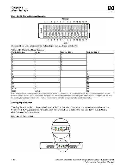
Figure 4.6.2.2 Slot and Address Illustration<br />
Blocked<br />
Addresses<br />
0 1 2 3 4 5 6 8 9 10 11 12 13 14<br />
1 2 3 4 5 6 7 8 9 10 11 12 13 14<br />
Slots<br />
<strong>Disk</strong> and BCC SCSI addresses for full and split bus mode are as follows:<br />
Table 4.6.2.8 Slot and Address Summary<br />
Physical <strong>Disk</strong> Slot Full Bus Split Bus (BCC A) Split Bus (BCC B)<br />
1 0 0<br />
2 1 1<br />
3 2 2<br />
4 3 3<br />
5 4 4<br />
6 5 5<br />
7 6 6<br />
8 8 8<br />
9 9 9<br />
10 10 10<br />
11 11 11<br />
12 12 12<br />
13 13 13<br />
14 14 14<br />
BCC A 15 15<br />
BCC B See Note 15<br />
Note: In split bus mode, the enclosure monitor circuitry on each BCC utilizes SCSI address 15. This is allowable since each BCC is connected to a separate SCSI bus.<br />
However, when the enclosure is in full bus mode and the separate SCSI busses on the midplane are connected together and the enclosure is configured with two BCCs,<br />
the secondary BCC enclosure monitor circuitry is inactive. One disk must be removed to corresponding to the second HBA on the bus.<br />
Setting Dip Switches<br />
Two Dip Switch banks on the rear bulkhead of BCC A (left slot) determine bus architecture and some bus<br />
behavior. If BCC A is removed, then the Dip Switches on BCC B define the bus. See Table 4.6.2.9 for a<br />
description of switch settings.<br />
Figure 4.6.2.3 Switch Bank 1<br />
4-84 HP e3000 Business Servers Configuration Guide – Effective 1/04<br />
Information Subject to Change