4.6.2–HP StorageWorks Disk System 2300 (DS2300)
4.6.2–HP StorageWorks Disk System 2300 (DS2300)
4.6.2–HP StorageWorks Disk System 2300 (DS2300)

You also want an ePaper? Increase the reach of your titles
YUMPU automatically turns print PDFs into web optimized ePapers that Google loves.
4.6.2—HP <strong>StorageWorks</strong> <strong>Disk</strong> <strong>System</strong> <strong>2300</strong> (DS<strong>2300</strong>)<br />
Description<br />
Chapter 4<br />
Mass Storage<br />
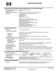
The HP <strong>StorageWorks</strong> <strong>Disk</strong> <strong>System</strong> <strong>2300</strong> is a fourteen-slot Ultra160 SCSI (160 MB/s LVD SCSI) capable<br />
interface storage enclosure. The enclosure is 3 EIA units (3U) high and consists of a single bay in front that<br />
has 14 vertically oriented hot-swappable disk module slots. The low voltage differential Ultra160 SCSI bus<br />
provides a data transfer rate of up to 160 MB/s. The DS<strong>2300</strong> has a storage capacity of up to one terabyte in a<br />
single enclosure. The DS<strong>2300</strong> is intended as a stand-alone JBOD, connected to a host, or hosts (up to two).<br />
Modular and redundant components are easy to upgrade and maintain. <strong>Disk</strong>s, fans, power supplies, and Bus<br />
Control Cards (BCCs) are replaceable parts that plug into individual slots in the front and back of the disk<br />
system. Redundant fans and power supplies can be removed and replaced without interrupting storage<br />
operations. <strong>Disk</strong>s also can be replaced with the system on and with only the affected file systems taken offline.<br />
Hewlett-Packard technical support is optional for these procedures.<br />
A switchable, SES or SAF-TE, environmental monitoring controller and HP software enable remote monitoring<br />
and diagnostics. Sensors on the BCCs monitor the disk system environment, including temperature, voltage,<br />
fan speed, and component status. A not-for-resale version of Command View SDM is included with the<br />
enclosure providing monitoring and diagnostic capabilities for many configurations. For MPE/iX<br />
environments, the status of the enclosure controller and disk drives can be monitored using cstm. Command<br />
View SDM is not supported on MPE/iX.<br />
This storage enclosure is available in field rack, factory rack, and deskside pedestal configurations. A<br />
minimum of one disk drive must be installed for the <strong>Disk</strong> <strong>System</strong> <strong>2300</strong> to function.<br />
The <strong>Disk</strong> <strong>System</strong> <strong>2300</strong> also includes a product manual, a VHDTS68 LVD/SE terminator, disk drive filler panels,<br />
a BCC filler panel and AC power cords.<br />
The DS<strong>2300</strong> will support new Ultra320 drives that will replace the existing Ultra160 drives and offer new<br />
capacity and performance points, including 73-GB 15K RPM and 146-GB 10K RPM drives. However, the<br />
enclosure will only support host connectivity at U160 transfer rates. If you are using a U320 host bus adapter,<br />
you may need to manually set it’s transfer speed to 160Mb/s.<br />
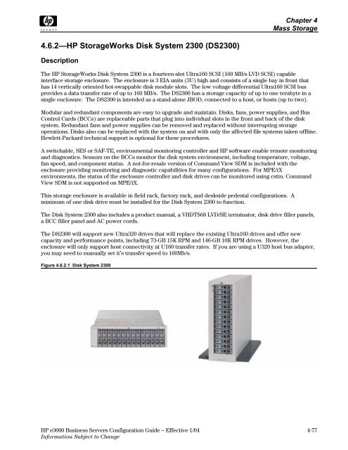
Figure 4.6.2.1 <strong>Disk</strong> <strong>System</strong> <strong>2300</strong><br />
HP e3000 Business Servers Configuration Guide – Effective 1/04 4-77<br />
Information Subject to Change
Chapter 4<br />
Mass Storage<br />
Part Numbers<br />
Table 4.6.2.1 <strong>Disk</strong> <strong>System</strong> <strong>2300</strong>—Field rack<br />
Product/Option Number Description<br />
A6490A <strong>Disk</strong> <strong>System</strong> <strong>2300</strong> field rack enclosure<br />
A6490AE <strong>Disk</strong> <strong>System</strong> <strong>2300</strong> field rack enclosure (empty enclosure for distributor stocking – disk drives cannot be integrated)<br />
A6491A Redundant Controller for HP DS<strong>2300</strong><br />
A6491A option 0D1 Redundant Controller for HP DS<strong>2300</strong> installed into the enclosure<br />
A6571A 36-GB 10K RPM LVD Ultra320 disk module add-on<br />
A6571A option OD1 36-GB 10K RPM LVD Ultra320 disk module installed into the A5675A field rack enclosure<br />
A7285A 73-GB 10K RPM LVD Ultra320 disk module add-on<br />
A7285A option OD1 73-GB 10K RPM LVD Ultra320 disk module installed into the A5675A field rack enclosure<br />
A7286A 73-GB 15K RPM LVD Ultra320 disk module add-on<br />
A7286A option OD1 73-GB 15K RPM LVD Ultra320 disk module installed into the A5675A field rack enclosure<br />
A7287A 146-GB 10K RPM LVD Ultra320 disk module add-on<br />
A7287A option OD1 146-GB 10K RPM LVD Ultra320 disk module installed into the A5675A field rack enclosure<br />
A7328A 18-GB 15K RPM LVD Ultra320 disk module add-on<br />
A7328A option OD1 18-GB 15K RPM LVD Ultra320 disk module installed into the A5675A field rack enclosure<br />
A7329A 36-GB 15K RPM LVD Ultra320 disk module add-on<br />
A7329A option OD1 36-GB 15K RPM LVD Ultra320 disk module installed into the A5675A field rack enclosure<br />
Note: The rack kit for the field rack option must be ordered separately.<br />
Table 4.6.2.2 <strong>Disk</strong> <strong>System</strong> <strong>2300</strong>—Factory rack<br />
Product/Option Number Description<br />
A6490AZ <strong>Disk</strong> <strong>System</strong> <strong>2300</strong> factory rack enclosure<br />
A6491A Redundant Controller for HP DS<strong>2300</strong><br />
A6491A option 0D1 Redundant Controller for HP DS<strong>2300</strong> installed into the enclosure<br />
A6571A 36-GB 10K RPM LVD Ultra320 disk module add-on<br />
A6571A option OD1 36-GB 10K RPM LVD Ultra320 disk module installed into the A5675A field rack enclosure<br />
A7285A 73-GB 10K RPM LVD Ultra320 disk module add-on<br />
A7285A option OD1 73-GB 10K RPM LVD Ultra320 disk module installed into the A5675A field rack enclosure<br />
A7286A 73-GB 15K RPM LVD Ultra320 disk module add-on<br />
A7286A option OD1 73-GB 15K RPM LVD Ultra320 disk module installed into the A5675A field rack enclosure<br />
A7287A 146-GB 10K RPM LVD Ultra320 disk module add-on<br />
A7287A option OD1 146-GB 10K RPM LVD Ultra320 disk module installed into the A5675A field rack enclosure<br />
A7328A 18-GB 15K RPM LVD Ultra320 disk module add-on<br />
A7328A option OD1 18-GB 15K RPM LVD Ultra320 disk module installed into the A5675A field rack enclosure<br />
A7329A 36-GB 15K RPM LVD Ultra320 disk module add-on<br />
A7329A option OD1 36-GB 15K RPM LVD Ultra320 disk module installed into the A5675A field rack enclosure<br />
Note: The rack kit for the factory rack is included with this option.<br />
Table 4.6.2.3 <strong>Disk</strong> <strong>System</strong> <strong>2300</strong>—Deskside<br />
Product/Option Number Description<br />
A6490AD <strong>Disk</strong> <strong>System</strong> <strong>2300</strong> deskside disk enclosure<br />
A6490ED <strong>Disk</strong> <strong>System</strong> <strong>2300</strong> deskside disk enclosure (empty enclosure for distributor stocking – disk drives cannot be integrated)<br />
A6491A Redundant Controller for HP DS<strong>2300</strong><br />
A6491A option 0D1 Redundant Controller for HP DS<strong>2300</strong> installed into the enclosure<br />
A6571A 36-GB 10K RPM LVD Ultra320 disk module add-on<br />
A6571A option OD1 36-GB 10K RPM LVD Ultra320 disk module installed into the A5675A field rack enclosure<br />
A7285A 73-GB 10K RPM LVD Ultra320 disk module add-on<br />
A7285A option OD1 73-GB 10K RPM LVD Ultra320 disk module installed into the A5675A field rack enclosure<br />
A7286A 73-GB 15K RPM LVD Ultra320 disk module add-on<br />
A7286A option OD1 73-GB 15K RPM LVD Ultra320 disk module installed into the A5675A field rack enclosure<br />
A7287A 146-GB 10K RPM LVD Ultra320 disk module add-on<br />
A7287A option OD1 146-GB 10K RPM LVD Ultra320 disk module installed into the A5675A field rack enclosure<br />
A7328A 18-GB 15K RPM LVD Ultra320 disk module add-on<br />
A7328A option OD1 18-GB 15K RPM LVD Ultra320 disk module installed into the A5675A field rack enclosure<br />
A7329A 36-GB 15K RPM LVD Ultra320 disk module add-on<br />
A7329A option OD1 36-GB 15K RPM LVD Ultra320 disk module installed into the A5675A field rack enclosure<br />
4-78 HP e3000 Business Servers Configuration Guide – Effective 1/04<br />
Information Subject to Change
Chapter 4<br />
Mass Storage<br />
Table 4.6.2.4 <strong>Disk</strong> <strong>System</strong> <strong>2300</strong>—Accessories, Enterprise <strong>System</strong>s<br />
Product/Option Number Description<br />
A6209A HP <strong>System</strong>/E Rack Rail Kit<br />
A6244A C278xx rackmount Hardware Kit<br />
A6496A NT/Rittal Rack Rail Kit<br />
A6498A Two Post Rack Rail Kit<br />
C2373A SCSI Cable 2-meter VHDTS68 M/M Multimode<br />
C2373A option 0D1 SCSI Cable 2-meter VHDTS68 M/M Multimode integrated into enclosure packaging<br />
C2374A SCSI Cable 5-meter VHDTS68 M/M Multimode<br />
C2374A option 0D1 SCSI Cable 5-meter VHDTS68 M/M Multimode integrated into enclosure packaging<br />
C2375A SCSI Cable 10-meter VHDTS68 M/M Multimode<br />
C2375A option 0D1 SCSI Cable 10-meter VHDTS68 M/M Multimode integrated into enclosure packaging<br />
C2362B SCSI Cable 2.5-meter VHDTS68/HDTS68 M/M Multimode<br />
C2362B option 0D1 SCSI Cable 2.5-meter VHDTS68/HDTS68 M/M Multimode integrated into enclosure packaging<br />
C2365B SCSI Cable 5-meter VHDTS68/HDTS68 M/M Multimode<br />
C2365B option 0D1 SCSI Cable 5-meter VHDTS68/HDTS68 M/M Multimode integrated into enclosure packaging<br />
C2363B SCSI Cable 10-meter VHDTS68/HDTS68 M/M Multimode<br />
C2363B option 0D1 SCSI Cable 10-meter VHDTS68/HDTS68 M/M Multimode integrated into enclosure packaging<br />
C2370A SCSI Terminator LVD/SE VHDTS68<br />
Notes: The <strong>System</strong> Integration Specification Plan (SISP), product number A3142B must be ordered with the server for a complete factory assembled server/storage<br />
configuration.<br />
Supported Servers and HBAs<br />
Table 4.6.2.5 Supported PA-RISC Platforms<br />
<strong>System</strong> Class HBA Description Bus<br />
HP e3000 A6828A Single-port Ultra160 Adapter PCI<br />
A6829A Dual-port Ultra160 Adapter (N-Class only) PCI<br />
HP 9000 A-/N-/L-/V-Class, Superdome A5149A Single-port Ultra2 SCSI HBA PCI<br />
A6828A Single-port Ultra160 Adapter (see note 2) PCI<br />
A5150A Dual-port Ultra2 SCSI HBA PCI<br />
A6829A Dual-port Ultra160 Adapter (see note 2) PCI<br />
A5838A Dual-port 100Base-T/Dual-Port Wide Ultra2 HBA PCI<br />
A5856A RAID 4si – 4-port Ultra2 LVD/SE RAID HBA PCI<br />
rp5400 series, rp7400, rp7410 rp8400 A5149A Single-port Ultra2 SCSI HBA PCI<br />
A6828A Single-port Ultra160 Adapter PCI<br />
A6829A Dual-port Ultra160 Adapter PCI<br />
A5856A RAID 4si – 4-port Ultra2 LVD/SE RAID HBA PCI<br />
Itanium rx4610, rx9610 A5150A Dual-port Ultra2 SCSI HBA PCI<br />
A5159A Dual-port FWD SCSI (PCI Bus) adapter PCI<br />
Workstations B-/C-/J-Class A4999A Ultra2 Low Voltage Differential SCSI HBA PCI<br />
Note 1: A-, C-, L-, and N-Class systems, as well as, rp2400, rp5400, rp74x0, and rp8400 core I/O cards are supported on the disk system <strong>2300</strong>.<br />
Note 2: The Ultra160 SCSI HBAs are not supported on Superdome, V-Class, rp8400, and rp7410. In addition, the Ultra160 SCSI HBAs do not have multi-initiator<br />
support. Please use the Ultra2 SCSI cards for multi-initiator applications. Patches for both of these issues are currently being created. Contact SISL for additional<br />
information.<br />
HP e3000 Business Servers Configuration Guide – Effective 1/04 4-79<br />
Information Subject to Change
Chapter 4<br />
Mass Storage<br />
Supported HBAs for Non-PA-RISC <strong>System</strong>s<br />
HP NetServer customers should use the same product numbers as HP 9000 customers. Customers wishing to<br />
stock empty enclosures should order the empty enclosure products (A6490AE and A6490ED).<br />
Table 4.6.2.6 HP NetServer Supported PCI—Host Bus Adapters, Commercial <strong>System</strong>s<br />
Product Number Description<br />
C7430A PCI Ultra2 wide Host Bus Adapter for NetServers<br />
D5025A HP Ultra/Wide SCSI adapter for NetServers<br />
D9161A NetRAID 4M/64 Host Bus Adapter for HP NetServers<br />
D9351A NetRAID 4M/128 Host Bus Adapter for HP NetServers<br />
P3413A Single-port Ultra3 SCSI Host Bus Adapter for HP NetServers<br />
P3410A NetRAID 1M Ultra3 SCSI Host Bus Adapter<br />
P3411A/B NetRAID 2M Ultra3 SCSI Host Bust Adapter<br />
P3475A/B NetRAID 2M Ultra3 SCSI Host Bust Adapter<br />
Operating <strong>System</strong>s Supported with DS<strong>2300</strong><br />
• HP-UX (11.0 and later)<br />
• Novell NetWare (5.1, 6.0, 6.5)<br />
• RedHat Linux (6.2, 7.0, 7.1, AS2.1)<br />
• Microsoft NT 4.0 Server and Enterprise<br />
• Microsoft Windows 2000 Server and Advanced Server<br />
• Microsoft Windows 2003 Server<br />
• SCO UnixWare7.1.1<br />
• SCO OpenServer 5.0.6<br />
• MPE/iX 7.0 Express 1 or later<br />
For more specific information about supported operating systems, refer to SPOCK @<br />
http://turbo.rose.hp.com/spock/<br />
4-80 HP e3000 Business Servers Configuration Guide – Effective 1/04<br />
Information Subject to Change
Features<br />
Chapter 4<br />
Mass Storage<br />
The disk system occupies 3.0 EIA units in a standard 19-inch rack. <strong>Disk</strong> drives mount in the front of the system.<br />
Redundant power supplies, fans, and BCCs mount in the back.<br />
Table 4.6.2.7 <strong>Disk</strong> <strong>System</strong> <strong>2300</strong> Summary<br />
Functionality<br />
<strong>Disk</strong> <strong>System</strong> <strong>2300</strong><br />
Rackmount<br />
Number of 3.5 inch mechanisms<br />
<strong>Disk</strong> Drive Support<br />
14 LP<br />
18.2 GB 10K Ultra160 SCSI Yes<br />
These drives are no longer orderable, but are kept<br />
18.2 GB 15K Ultra160 SCSI Yes<br />
here for reference.<br />
36 GB 10K Ultra160 SCSI Yes<br />
36 GB 15K Ultra160 SCSI Yes<br />
73 GB 10K Ultra160 SCSI Yes<br />
36 GB 10K Ultra320 SCSI Yes, at 160 MB/s<br />
73 GB 10K Ultra320 SCSI Yes, at 160 MB/s<br />
73 GB 15K Ultra320 SCSI Yes, at 160 MB/s<br />
146 GB 10K Ultra320 SCSI Yes, at 160 MB/s<br />
18 GB 15K Ultra320 SCSI Yes, at 160 MB/s<br />
36 GB 15K Ultra320 SCSI Yes, at 160 MB/s<br />
Enclosures Per Rack HP Original Rack (install base) HP Rack <strong>System</strong>/E<br />
1-meter rack 5 8<br />
1.6-meter rack 8 11<br />
2-meter rack<br />
High Availability Functionality<br />
10 13<br />
Hot Plug Yes<br />
Boot (Single-host) Yes<br />
Root Yes<br />
Swap Yes<br />
Redundant power Supply\Fan Yes<br />
Number of power cords 2<br />
Number of Ultra SCSI Busses<br />
1 LP - Low-Profile, 1 inch high mechanisms<br />
2<br />
Power Switch<br />
Located in the upper right corner of the front of the disk system, the power switch interrupts DC power from<br />
the power supplies to the BCCs and other internal components. Input AC power to the power supplies is<br />
controlled by the power cords and AC source.<br />
High Availability<br />
High availability is a general term describing computer systems that are designed to minimize planned and<br />
unplanned downtime. The <strong>Disk</strong> <strong>System</strong> <strong>2300</strong> provides high availability through the following features:<br />
• Hot-pluggable, high-capacity, high-speed disks<br />
• Redundant, hot-pluggable, and user-replaceable fans, power supplies, and BCCs<br />
• Support for mirrored disks.<br />
• Online BCC firmware upgrades.<br />
• Hardware event monitoring and real-time error reporting<br />
HP e3000 Business Servers Configuration Guide – Effective 1/04 4-81<br />
Information Subject to Change
Chapter 4<br />
Mass Storage<br />
Environmental Services<br />
Environmental services circuitry monitors the following elements:<br />
• Fan rotation<br />
• Power supply outputs<br />
• Power supply status<br />
• <strong>Disk</strong> drive status, presence<br />
• BCC status<br />
• Temperature<br />
• Self-test results<br />
Each BCC reports the status of all elements in the disk system, even if the BCC does not have direct access to<br />
the element. Additionally, the EEPROM on each BCC stores 2 KB of configuration information and<br />
user-defined data, including the manufacturer serial number, and product number. The DS<strong>2300</strong> is equipped<br />
with a switchable environmental services controller to enable both SCSI enclosure services (SES) and SAF-TE.<br />
The DS<strong>2300</strong> ships with the environmental monitoring controller set to SAF-TE. Information on setting this<br />
controller is included in the following section titled configuration considerations.<br />
Hardware Event Monitoring<br />
For MPE/iX environments, the status of the enclosure controller and disk drives can be monitored using cstm.<br />
Command View SDM and Top Tools are not supported on MPE/iX.<br />
Command View SDM is primarily used in HP-UX environments to provide HW monitoring, diagnostics, and<br />
firmware download. It provides both a GUI and command line interface. Each DS<strong>2300</strong> ships with a<br />
not-for-resale version of this software. Command View SDM may use either the SES or SAF-TE setting on the<br />
environmental services controller. More environmental information can be gathered through Command View<br />
SDM using the SES environmental controller setting. The DS<strong>2300</strong> must be set on the SAF-TE controller setting<br />
when Command View SDM is used in a Windows environment.<br />
Note: Command View SDM does not function with a NetRAID card.<br />
Top Tools is the most likely event-monitoring tool to be used in a NetServer environment. Top Tools requires<br />
that SAF-TE be enabled on the environmental services controller. Top Tools is available on the Navigator CD<br />
or Top Tools CD that ships with the NetServer system.<br />
In addition, the NetRAID 4M card utilizes the FAST Utility (Windows only) to provide for event monitoring.<br />
The rest of the NetRAID cards use the NetRAID Assistant (Windows only) utility. Netware uses Megamon<br />
behind an HBA or NetRAID card. These utilities are included on the Navigator CD that ships with NetServer<br />
systems. The FAST Utility, NetRAID Assistant, and Megamon all use the SAF-TE controller setting.<br />
Status Indicators<br />
LEDs on the disk system enable you to detect and replace failed components and thereby prevent or minimize<br />
downtime for users. On the front of the disk system, a pair of LEDs indicate the status of the disk system.<br />
Each disk module contains two LEDs. The LEDs indicate the following conditions:<br />
• The system power LED indicates that power is on or off.<br />
• The system fault LED indicates whether or not a fault has occurred anywhere in the disk system.<br />
• At the bottom of each disk module, the left LED indicates the presence of I/O activity on the disk.<br />
• The second LED on the right of each disk module should be green indicating drive presence. It can be<br />
flashed to help an engineer locate the disk for physical inspection or removal. A drive fault is indicated by<br />
an amber color.<br />
LEDs on the back of the disk system indicate status of the replaceable components and the SCSI bus. See<br />
users manual for more specific information.<br />
4-82 HP e3000 Business Servers Configuration Guide – Effective 1/04<br />
Information Subject to Change
Configuration Considerations<br />
Cables<br />
Chapter 4<br />
Mass Storage<br />
The cables must be explicitly ordered for both factory-racked, field-racked and deskside configurations. They<br />
are offered as separate products but may be included in the enclosure box on the factory-integrated products<br />
(A6490A, A6490AD, A6490AV, A6490AZ).<br />
Note: Support and use of in-line terminated (ILT) cables is prohibited. Use of ILT cables with this product<br />
may result in data corruption.<br />
<strong>Disk</strong> Modules<br />
• Utilizes the Common HP <strong>Disk</strong> Carrier with downloadable firmware<br />
• Non-OS Specific <strong>Disk</strong> Firmware<br />
• Hot swappable disk modules<br />
• Front Access only<br />
• Rotational vibration damping control<br />
• Easy insertion/removal (accomplished with a cam handle)<br />
• Positive lock-in<br />
• LED status indicator<br />
• ESD grounding<br />
At least one HDD is required for the DS<strong>2300</strong> to function in a single BCC configuration. If a second BCC is<br />
added, at least two HDDs should be in the enclosure.<br />
Note: Since disks require exclusive access, data is unavailable during the disk firmware download.<br />
Storage Capacity<br />
The <strong>Disk</strong> <strong>System</strong> <strong>2300</strong> has fourteen (14) slots for low profile (1-inch width) LVD disk mechanisms. The<br />
enclosure can accept multiple-capacity drives such as 18-, 36-, or 73-GB simultaneously, subject to host file<br />
system restrictions. Further, the disk system can accept different spindle speed drives and different interface<br />
speed drives. The bus will negotiate each disk individually maximizing its throughput. These drive capacity<br />
notes are tied to the printing of this document. Future capacities will be made available for this enclosure.<br />
Upgradability<br />
You can increase disk system storage capacity by:<br />
• Replacing disk drives with higher-capacity disk drives<br />
• Adding disks in unused slots<br />
None of these actions require shutting down the product, but some may require the use of system utilities to<br />
manage file systems.<br />
Enclosure Addressing and SCSI IDs<br />
The disk system has 14 available disk slots; SCSI addressing does not follow a “one-to-one” relationship<br />
between slot positions and SCSI addresses. Slot assignments and SCSI addresses are shown below. In full bus<br />
mode, the SCSI address 7 is reserved for the host bus adapter. If more than one HBA connects to the disk<br />
system then a disk module must be removed from the slot that corresponds to the SCSI address of the<br />
additional host bus adapter. In split bus mode, slots 1 through 7 are on one bus and slots 8 through 14 are on<br />
the other bus.<br />
HP e3000 Business Servers Configuration Guide – Effective 1/04 4-83<br />
Information Subject to Change
Chapter 4<br />
Mass Storage<br />
Figure 4.6.2.2 Slot and Address Illustration<br />
Blocked<br />
Addresses<br />
0 1 2 3 4 5 6 8 9 10 11 12 13 14<br />
1 2 3 4 5 6 7 8 9 10 11 12 13 14<br />
Slots<br />
<strong>Disk</strong> and BCC SCSI addresses for full and split bus mode are as follows:<br />
Table 4.6.2.8 Slot and Address Summary<br />
Physical <strong>Disk</strong> Slot Full Bus Split Bus (BCC A) Split Bus (BCC B)<br />
1 0 0<br />
2 1 1<br />
3 2 2<br />
4 3 3<br />
5 4 4<br />
6 5 5<br />
7 6 6<br />
8 8 8<br />
9 9 9<br />
10 10 10<br />
11 11 11<br />
12 12 12<br />
13 13 13<br />
14 14 14<br />
BCC A 15 15<br />
BCC B See Note 15<br />
Note: In split bus mode, the enclosure monitor circuitry on each BCC utilizes SCSI address 15. This is allowable since each BCC is connected to a separate SCSI bus.<br />
However, when the enclosure is in full bus mode and the separate SCSI busses on the midplane are connected together and the enclosure is configured with two BCCs,<br />
the secondary BCC enclosure monitor circuitry is inactive. One disk must be removed to corresponding to the second HBA on the bus.<br />
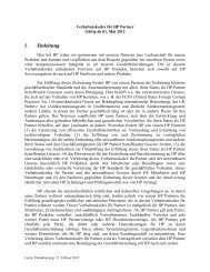
Setting Dip Switches<br />
Two Dip Switch banks on the rear bulkhead of BCC A (left slot) determine bus architecture and some bus<br />
behavior. If BCC A is removed, then the Dip Switches on BCC B define the bus. See Table 4.6.2.9 for a<br />
description of switch settings.<br />
Figure 4.6.2.3 Switch Bank 1<br />
4-84 HP e3000 Business Servers Configuration Guide – Effective 1/04<br />
Information Subject to Change
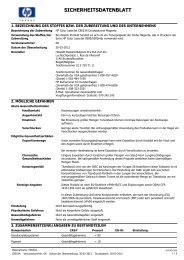
Figure 4.6.2.4 Switch Bank 2<br />
Enables or disables SCSI bus<br />
reset for the above conditions<br />
Enable<br />
Disable<br />
BCC Hot Swap<br />
Power Fail<br />
<strong>Disk</strong> Hot Swap<br />
Chapter 4<br />
Mass Storage<br />
Table 4.6.2.9 Dip Switch Settings<br />
Switch Bank 1 OFF = | ON = 0<br />
1 Full Bus Creates a single bus of up to 14 disk drives Splits the bus into two buses, up to 7 disk drives each<br />
2 SES/SAF-TE SAF-TE Mode SES Mode<br />
Switch Bank 2 OFF = | ON = 0<br />
1 Bus Reset: Hot Swap <strong>Disk</strong> Automatically issues a SCSI bus reset when a disk is<br />
removed or inserted<br />
Lets the host detect change and determine action<br />
2 Bus Reset: Power Fail Issues a SCSI reset when the power supply/fan module<br />
indicates it will go offline<br />
3 Bus Reset: Hot Swap BCC Automatically issues a SCSI bus reset when a BCC is<br />
removed or inserted<br />
Lets the host detect change and determine action<br />
Note: The switch settings on BCC A must match the switch settings on BCC B. All DS<strong>2300</strong> enclosures will be shipped set to Full Bus Mode, SAF-TE enabled with all SCSI<br />
Bus Reset switches enabled.<br />
Sites choose Dip Switch options according to their priorities and preferences. High availability sites, for<br />
example, may want automatic bus reset on whereas high performance sites may choose to turn it off. The<br />
following table gives some of the typical reasons for choosing specific Dip Switch settings.<br />
Table 4.6.2.10 Dip Switch Reasoning<br />
Switch Bank 1 OFF = | ON = 0<br />
1 Full Bus a. Full-bus mode is the only way to access all 14 disks a. Split buses allow you to mirror disks within the disk<br />
with one BCC.<br />
system.<br />
b. With two BCCs, full-bus mode allows two external b. Split-bus mode uses fewer IDs on the bus, improving<br />
connections to the bus.<br />
c. Full-bus mode with two BCCs gives redundant<br />
environmental services.<br />
bus performance.<br />
2 SES/SAF-TE SAF-TE is required for most non HP-UX platforms. SES is required for HP-UX using EMS.<br />
Switch Bank 2 OFF = | ON = 0<br />
1 Bus Reset: Hot Swap <strong>Disk</strong> Automatic bus reset reduces the chances of data<br />
a. No bus reset reserves bus control to the host.<br />
corruption and saves the 30 to 60 seconds that the host b. No bus reset avoids resetting the entire bus for one<br />
would spend determining that a disk is unavailable. Bus<br />
reset signals the host to resend outstanding I/O requests.<br />
disk.<br />
2 Bus Reset: Power Fail SCSI bus is held in reset as power goes down, thus<br />
avoiding data corruption.<br />
Bus control is restricted to the host.<br />
3 Bus Reset: Hot Swap BCC Automatic SCSI bus reset reduces the chance of data a. No bus reset reserves bus control to the host.<br />
corruption when a BCC is inserted or removed from the b. No bus reset avoids resetting the entire bus for one<br />
disk system.<br />
disk.<br />
HP e3000 Business Servers Configuration Guide – Effective 1/04 4-85<br />
Information Subject to Change
Chapter 4<br />
Mass Storage<br />
Termination<br />
Termination is a requirement for the SCSI bus connecting the disk system and the host or other device<br />
connected to the disk system. Termination is required and must be enabled whenever the disk system is at the<br />
end of a bus. The LVD/SE VHDTS68-pin terminator is included with the <strong>Disk</strong> <strong>System</strong> <strong>2300</strong> product.<br />
Topologies<br />
The <strong>Disk</strong> <strong>System</strong> <strong>2300</strong> supports multiple configuration options based on either single or dual host<br />
environments. This section is not meant to be representative of every supported topology but merely represent<br />
typical configurations.<br />
Single Host, One <strong>Disk</strong> <strong>System</strong><br />
This configuration presents the most basic setup of a single host connected to a single DS<strong>2300</strong> disk enclosure.<br />
Notice that the unused SCSI port on the BCC is terminated because it resides at the end of the SCSI chain.<br />
Figure 4.6.2.5<br />
Single Host, Dual HBA, Single <strong>Disk</strong> <strong>System</strong> (Duplexing)<br />
Note: The following configuration is not supported on MPE/iX.<br />
This configuration requires the installation of two HBA ports on the host. Both ports connect to the <strong>Disk</strong><br />
<strong>System</strong> <strong>2300</strong>. This technique, known as duplexing, increases throughput by providing two paths to the data<br />
and provides some level of redundancy, as the loss of a single HBA in the host would not cause a complete<br />
system failure. The host would continue to operate with some performance degradation. This configuration is<br />
only supported in an HP-UX environment with LVM software. It is recommended that LVM software be<br />
installed and the pvlinks feature used to create the redundant data path.<br />
An alternative configuration utilizing this same physical cable configuration would be to split the bus and<br />
create a software mirror within the DS<strong>2300</strong> enclosure.<br />
Figure 4.6.2.6<br />
4-86 HP e3000 Business Servers Configuration Guide – Effective 1/04<br />
Information Subject to Change
Dual Host, Dual HBA, Single <strong>Disk</strong> <strong>System</strong><br />
Chapter 4<br />
Mass Storage<br />
This configuration allows two servers to share a single DS<strong>2300</strong> in split bus mode. Each bus is independent of<br />
the other and is not affected by activity on the other bus. Note that this configuration requires two bus control<br />
cards and only one server is supported on each BCC. The unused SCSI port on the BCC must be terminated.<br />
Figure 4.6.2.7<br />
Dual Host, Dual HBA, Dual <strong>Disk</strong> <strong>System</strong>s (Cluster)<br />
Note: The following configuration is not supported on MPE/iX.<br />
This completely redundant configuration provides host and disk system redundancy if clustering software and<br />
mirroring software are employed. This configuration is only valid when two BCC cards are used. The loss of a<br />
host, HBA or SCSI channel would allow the system to continue to function, but with reduced functionality.<br />
This configuration is supported in a Microsoft Cluster Server environment with several HP NetServers.<br />
Further information may be obtained at the following URL:<br />
http://netserver.hp.com/products/high_availability/ms_supported_config.asp.<br />
MC/ServiceGuard support can be found at the following URL:<br />
http://haweb.cup.hp.com/Support/<strong>Disk</strong>Support.html.<br />
Note: These configurations do not use in-line terminated (ILT) cables. Use of ILT cables may result in<br />
data corruption.<br />
Figure 4.6.2.8<br />
HP e3000 Business Servers Configuration Guide – Effective 1/04 4-87<br />
Information Subject to Change
Chapter 4<br />
Mass Storage<br />
<strong>Disk</strong> Mirroring<br />
<strong>Disk</strong> mirroring is available through the use of the Mirror-UX software provided with the HP-UX operating<br />
system. <strong>Disk</strong> mirroring software is also available through other operating systems or through third party<br />
applications. MPE/iX utilizes HP Mirrored <strong>Disk</strong>/iX.<br />
Racking Considerations<br />
Rack/rail kits required for the DS<strong>2300</strong> disk system:<br />
• A6209A—HP <strong>System</strong> E Racking Kit<br />
• A6244A—HP Original Rack <strong>System</strong>s Racking Kit (rack kit and enclosure occupy 4U of rack space)<br />
• A6498A—Two Post Rack Rail Kit<br />
• A6496A—NT/Rittal Rack Rail Kit<br />
Powerfail Protection<br />
A UPS is required for powerfail protection for the <strong>Disk</strong> <strong>System</strong> <strong>2300</strong>. A 500 VA (minimum) UPS is<br />
recommended for use with the <strong>Disk</strong> <strong>System</strong> <strong>2300</strong>.<br />
Recommended Rack Configurations<br />
The <strong>Disk</strong> <strong>System</strong> <strong>2300</strong> has been tested for thermal profiles in the HP <strong>System</strong>-E Racks. The following are the<br />
recommended configurations for a 1.25-meter, 1.6-meter and 2-meter rack.<br />
Table 4.6.2.11 Rack Configurations<br />
Rack size Maximum<br />
Number of<br />
DS<strong>2300</strong><br />
Empty<br />
EIAs<br />
PDUs<br />
Needed 3,4<br />
Input Voltage 1 Input Current per<br />
Power Supply 1,2<br />
RB2, 1.25-meter, 25 U 8 1 6 120 V 4.8 A continuous,<br />
19.4 A inrush<br />
RB2, 1.25-meter, 25 U 8 1 4 240 V 2.0 A continuous,<br />
19.4 A inrush<br />
RB2, 1.6-meter, 33 U 11 0 4 240 V 2.0 A continuous,<br />
19.4 A inrush<br />
RB2, 2.0-meter, 41 U 13 2 6 240 V 2.0 A continuous,<br />
19.4 A inrush<br />
Minimum European and American<br />
Standard Circuit Breaker Rating per Bus<br />
(two buses required for redundancy) 2<br />
Type, trip range Current<br />
D, 10-20X 40 A (5)<br />
K, 8-12X 40 A (5)<br />
C, 5-10X 40 A (5)<br />
730-5, 7X 40 A (5)<br />
D, 10-20X 16 A<br />
K, 8-12X 25 A<br />
C, 5-10X 32 A<br />
730-4, 12X 20 A<br />
D, 10-20X 25 A<br />
K, 8-12X 40 A<br />
C, 5-10X 50 A<br />
730-5, 10X 30 A<br />
D, 10-20X 32 A<br />
K, 8-12X 40 A<br />
C, 5-10X 63 A<br />
730-5, 10X 30 A<br />
1 Label rating of DS<strong>2300</strong> power supply is 100-240 V, 4.8-2.0 A. This indicates the steady state current.<br />
2 Maximum inrush current is 19.4 A. Current = (19.4 A inrush/minimum trip point) × total power supplies per bus. This specifies the minimum breaker rating for inrush<br />
current but does not necessarily satisfy the steady state current requirement. Choose a higher standard rating of breaker that satisfies the steady state current also.<br />
3 Calculation of number of PDUs required is as follows, (120 V example):<br />
a. 16 A PDU/4.8 A nominal input per power supply = 3 power supplies per PDU max<br />
b. 8 chassis’ per rack/3 power supplies per PDU max = 3 PDUs per bus<br />
c. 3 PDUs per bus × 2 redundant buses = 6 PDUs required<br />
4 PDU E7674-63001/5183-1837, is rated for 20 A. The derating is 80%, or 16 A maximum, which is stamped on the side of the PDU.<br />
5 Steady state current is much higher when operated at 120 V.<br />
4-88 HP e3000 Business Servers Configuration Guide – Effective 1/04<br />
Information Subject to Change
Support Information<br />
Warranty<br />
The DS<strong>2300</strong> includes a standard 3 Year, Next Day, On-Site warranty with the enclosure.<br />
Product Support Packs for Indirect Channel<br />
The support packs are on the disk system only and contains the support pricing of the drives.<br />
Chapter 4<br />
Mass Storage<br />
Table 4.6.2.12 Support Packs<br />
HP Service levels Support Packs—1 Year Support Packs—3 year<br />
Same Day N/A U2075A/U2075E<br />
24×7, on-site N/A U2076A/U2076E<br />
6-hour Call-to-Repair N/A U2077A/U2077E<br />
Note: Commercial channel product support pack codes ending with the letter “A” denote physical device support. Those ending with the letter “E” denote electronic<br />
support.<br />
Product Upfront Support Options for Direct Channel<br />
The Upfront Options are on the disk system only and contains the support pricing of the drives.<br />
Table 4.6.2.13 CATS Support Options<br />
HP Service Levels CATS Support Options—1 Year CATS Support Options—3 year<br />
Same Day H4402A/H4403A H4402Y/H4403Y<br />
24×7 H4404A/H4405A H4404Y/H4405Y<br />
6-hour Call-to-Repair H4385A N/A<br />
Business Continuity Support H4395A N/A<br />
Description of Services Offered<br />
The 02x are the post warranty support contractual monthly pricing available after the warranty. The 07x are<br />
the upgrade warranty support contractual monthly pricing available during the warranty.<br />
Table 4.6.2.14 Monthly Support Pricing Code Descriptions<br />
Code Description<br />
02A On-site 4 hour same day hardware response, Monday – Friday, business hours.<br />
07A 07A is available as a warranty upgrade to a 02A response level<br />
02C On-site next day hardware response, Monday – Friday, business hours (vary by country).<br />
07C 07C available as a warranty upgrade to a 02C response level<br />
02G On-site 4 hour same day hardware response, seven days a week, 24 hours a day.<br />
07G 07G available as a warranty upgrade to a 02G response level<br />
02V On-site six-hour hardware call-to-repair, seven days a week, 24 hours a day. Time begins when the original call to the call center is made.<br />
Recovery of operating system and other software are excluded from time commitment. Available only for customer sites up to 50 miles<br />
(80 km) from a primary HP Support Response Office.<br />
07V 07V available as a warranty upgrade to a 02V repair level<br />
02X On-site four-hour hardware call-to-restoration, seven days a week, 24 hours a day. Time begins when the original call to the call center is<br />
made. Restoration considered complete when an operating system prompt is re-established and the operating system is restored to the<br />
customer’s last configuration (or when the operating system is restored to a generic configuration for that operating system<br />
configuration). Time commitment does not include time needed for recovery of middleware, application software or data. Available only<br />
for customer sites up to 50 miles (80 km) from a primary HP Support Response Office. In order to purchase this level of response, the<br />
system must be part of a BCS contract.<br />
07X 07X available as a warranty upgrade to a 02X repair level<br />
HP e3000 Business Servers Configuration Guide – Effective 1/04 4-89<br />
Information Subject to Change
Chapter 4<br />
Mass Storage<br />
Product Specifications<br />
Table 4.6.2.15 Physical Dimensions<br />
Measure Metric English<br />
Width 44.8 cm 17.6 in<br />
Depth 50.5 cm 19.9 in<br />
Height 13.0 cm 5.1 in<br />
Weight of deskside enclosure w/out disk modules 37.3 kg 82 lbs<br />
Weight of deskside enclosure fully loaded 46.4 kg 102 lbs<br />
Weight of rack mount enclosure w/out disk modules 27.3 kg 60 lbs<br />
Weight of rack mount enclosure fully loaded 36.4 kg 80 lbs<br />
Table 4.6.2.16 Electrical Requirements<br />
Electrical Element Requirement<br />
Input Voltage Range 100-240 VAC Auto-ranging<br />
Line Frequency Range 50/60 Hz<br />
Published Input Voltage Range 100-240 VAC<br />
Published Line Frequency Range 50/60 Hz<br />
Input Current 100-240 VAC @ 4.8-2.0 Amp<br />
Maximum Surge Current 40 Amps peak<br />
Operating Temperatures<br />
If the storage system is installed in a multi-unit rack assembly, the operating ambient temperature of the rack<br />
environment may exceed room ambient temperature. The rack environment ambient temperature cannot<br />
exceed 38° Celsius (100° Fahrenheit). If your storage system contains less than 14 disk modules, the remaining<br />
empty slots require filler panels. These filler panels (part number A6198-60001), which are included with the<br />
DS<strong>2300</strong> product, ensure that the proper cooling is maintained within the storage system.<br />
Table 4.6.2.17 Climate Control<br />
Measure Type Range<br />
Temperature (dry bulb) Operating 5°C to +38°C<br />
Storage –40°C to +70°C<br />
Relative Humidity (non-condensing) Operating 10%-80% Relative Humidity at 28°C wet bulb<br />
Storage 10%-90% Relative Humidity at 28°C wet bulb<br />
Altitude (based on disks) Operating -1000 ft to +10,000 ft (3,048 meters) Storage 40,000 ft (12,092 meters)<br />
Heat Dissipation (maximum) Operating 500 watts<br />
4.<br />
4-90 HP e3000 Business Servers Configuration Guide – Effective 1/04<br />
Information Subject to Change