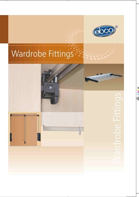
Wardrobe Fittings
You also want an ePaper? Increase the reach of your titles
YUMPU automatically turns print PDFs into web optimized ePapers that Google loves.
<strong>Wardrobe</strong> <strong>Fittings</strong><br />
<strong>Wardrobe</strong> <strong>Fittings</strong>
124<br />
Special Features<br />
Hi - Fold <strong>Fittings</strong> 200<br />
Ergonomically designed for overlay sliding shutters, Bottom Guide Track is hidden.<br />
Manufactured out of durable plastics.<br />
High precision rolling.<br />
Quick release mechanism provided.<br />
Templates provided for drilling.<br />
Specifications<br />
Item Code No. Max. Width<br />
of Each<br />
Shutter<br />
Hi -Fold <strong>Fittings</strong><br />
Runner Track<br />
Guide Track<br />
Fitting Instructions<br />
HFF 200<br />
HFF - RT<br />
HFF - GT<br />
500MM<br />
Max. Weight<br />
of Each<br />
Shutter<br />
10 Kgs.<br />
1. Refer drilling dimensions for cabinet & shutters. (Ref. Fig. 1 & 2).<br />
2. Fit the Runner track Guide track as required and screw them as shown.<br />
(Ref. Fig.2 & 2A).<br />
3. Fit click on / slip on Hinges (not provided) on one side of the shutter (Ref. Fig,3),<br />
Using Ø35 mm boring cutter.<br />
4. Fit the Folding Hinges in between the two shutters (Ref. Fig.3 & 3A) Template is<br />
provided for drill holes for the Folding Hinges. (Ref. Fig,3B).<br />
5. Fit Hinged Runner with Quick release and Hinged Guide with Quick release to the<br />
far side of second shutter. (Ref. Fig,3A), Using Ø35 mm boring cutter.<br />
6. Screw the Click on / Slip on hinge on to the Mounting plate which is fitted on the<br />
inside of the cabinet. (Ref. Fig.4).<br />
7. Bring second shutter close to the first shutter (Ref. Fig.5) and push U Pin to engage.<br />
(Ref. Fig.5A).<br />
8. Fold the shutters and engage roller into Runner Track Guide Track by pushing quick<br />
release (Ref.Fig.6) Shutters can also be disengaged by pulling quick release down.<br />
45.0<br />
Ø35.0<br />
12 deep<br />
Fig. 1<br />
'A'<br />
31.0 32.0 15.0<br />
4.0<br />
32.0<br />
'B'<br />
'B'<br />
32.0<br />
Ø35.0<br />
12 deep<br />
C<br />
'A'<br />
1.0<br />
2.0<br />
3.0<br />
4.0<br />
5.0<br />
'B'<br />
15.5<br />
15.0<br />
14.5<br />
14.0<br />
13.5<br />
Calculation for door width/door panels<br />
Door width = inside cabinet width + (2 x overlay)<br />
Door panel width = inside cabinet width - A<br />
For min. overlay 10 mm,<br />
C value = 4 mm<br />
+ (2 x overlay) / 2<br />
SINGLE HINGED<br />
RUNNER WITH<br />
QUICK RELEASE<br />
HINGED GUIDE<br />
WITH QUICK<br />
RELEASE<br />
Des. Reg. no. 205457<br />
FOLDING<br />
HINGE<br />
* Click-on Hinge or Slip-on Hinge are not included<br />
CABINET<br />
For overlay more than 10 mm,<br />
Side View of cabinet<br />
Shutter Drilling Dimensions<br />
C value = (overlay - 10) + 4<br />
Fig. 2 Fig. 2A<br />
25.0<br />
30.0 25.5<br />
46.0<br />
SHUTTER<br />
26.0<br />
15.0 Min.<br />
55.0 Min.<br />
HINGED RUNNER<br />
WITH QUICK RELEASE<br />
FOLDING<br />
HINGE<br />
HINGED GUIDE<br />
WITH QUICK RELEASE<br />
RUNNER TRACK<br />
CLICK ON HINGE (OVERLAY)*<br />
SLIP ON HINGE (OVERLAY)<br />
(4 Nos)<br />
GUIDE TRACK
Fig. 3<br />
2.0<br />
5.0<br />
32.0<br />
32.0<br />
Ø5. 0<br />
Fig. 3A<br />
Fig. 3B Fig. 4<br />
Fig. 5 Fig. 6<br />
RUNNER TRACK<br />
PUSH QUICK RELEASE<br />
TO ENGAGE<br />
IN THE TRACK<br />
PUSH QUICK RELEASE<br />
TO ENGAGE<br />
IN THE TRACK<br />
GUIDE TRACK<br />
125
126<br />
Special Features<br />
Hi - Fold <strong>Fittings</strong> 300<br />
Ergonomically designed for overlay sliding shutters, Bottom Guide Track is hidden.<br />
Manufactured out of durable plastics.<br />
High precision rolling.<br />
Quick release mechanism provided.<br />
Templates provided for drilling.<br />
Specifications<br />
Item Code No. Max. Width<br />
of Each<br />
Shutter<br />
Hi -Fold <strong>Fittings</strong><br />
Runner Track<br />
Guide Track<br />
Fitting Instructions<br />
HFF 300<br />
HFF - RT<br />
HFF - GT<br />
500MM<br />
Max. Weight<br />
of Each<br />
Shutter<br />
20 Kgs.<br />
1. Refer drilling dimensions for cabinet & shutters. (Ref. Fig. 1 & 2).<br />
2. Fit the Runner track Guide track as required and screw them as shown. (Ref. Fig.2 &<br />
2A).<br />
3. Fit click on / slip on Hinges (not provided) on one side of the shutter (Ref. Fig,3),<br />
Using Ø35 mm boring cutter.<br />
4. Fit the Folding Hinges in between the two shutters (Ref. Fig.3 & 3A) Template is provided<br />
for drill holes for the Folding Hinges. (Ref. Fig,3B).<br />
5. Fit Hinged Runner with Quick release and Hinged Guide with Quick release to the far<br />
side of second shutter. (Ref. Fig,3A), Using Ø35 mm boring cutter.<br />
6. Screw the Click on / Slip on hinge on to the Mounting plate which is fitted on the<br />
inside of the cabinet. (Ref. Fig.4).<br />
7. Bring second shutter close to the first shutter (Ref. Fig.5) and push U Pin to engage.<br />
(Ref. Fig.5A).<br />
8. Fold the shutters and engage rollers into Runner Track Guide Track by pushing quick<br />
release (Ref. Fig. 6) Shutters can also be disengaged by pulling quick release down.<br />
45.0<br />
Ø35.0<br />
12 deep<br />
Fig. 1<br />
31.0<br />
4.0<br />
32.0<br />
'B'<br />
'A'<br />
32.0 15.0<br />
'B'<br />
32.0<br />
32.0<br />
Ø35. 0<br />
12 de ep<br />
C<br />
'A'<br />
1.0<br />
2.0<br />
3.0<br />
4.0<br />
5.0<br />
'B'<br />
15.5<br />
15.0<br />
14.5<br />
14.0<br />
13.5<br />
Calculation for door width/door panels<br />
Door width = inside cabinet width + (2 x overlay)<br />
Door panel width = inside cabinet width - A<br />
For min. overlay 10 mm,<br />
C value = 4 mm<br />
+ (2 x overlay) / 2<br />
Des. Reg. no. 205457<br />
DOUBLE HINGED<br />
RUNNER WITH<br />
QUICK RELEASE<br />
HINGED GUIDE<br />
WITH QUICK<br />
RELEASE<br />
FOLDING<br />
HINGE<br />
FOLDING<br />
HINGE<br />
RUNNER TRACK<br />
* Click-on Hinge or Slip-on Hinge are not included<br />
CABINET<br />
30.0 25.5<br />
HINGED RUNNER<br />
WITH QUICK RELEASE<br />
HINGED GUIDE<br />
WITH QUICK RELEASE<br />
CLICK ON HINGE (OVERLAY)*<br />
SLIP ON HINGE (OVERLAY)<br />
(4 Nos)<br />
GUIDE TRACK<br />
For overlay more than 10 mm,<br />
Side View of Cabinet<br />
C value = (overlay - 10) + 4<br />
Shutter Drilling Dimensions Fig. 2 Fig. 2A<br />
25.0<br />
46.0<br />
64.0<br />
SHUTTER<br />
26.0<br />
15.0 Min.<br />
55.0 Min.
Fig. 3 Fig. 3A<br />
2.0<br />
5.0<br />
32.0<br />
32.0<br />
Ø50 .<br />
Fig. 3B Fig. 4<br />
PUSH U PIN TO ENGAGE<br />
Fig. 5A<br />
Fig. 5 Fig. 6<br />
RUNNER TRACK<br />
PUSH QUICK RELEASE<br />
TO ENGAGE<br />
IN THE TRACK<br />
PUSH QUICK RELEASE<br />
TO ENGAGE<br />
IN THE TRACK<br />
GUIDE TRACK<br />
127
128<br />
Special Features<br />
Fitting Instructions<br />
<strong>Wardrobe</strong> Rail <strong>Fittings</strong><br />
These oval wardrobe rail supports are die cast for strength and long life.<br />
Easy to fit and compatible with a special oval rail.<br />
<strong>Wardrobe</strong> rails are available in S.S 304 polished.<br />
Coat hooks are also available.<br />
System 32 compatible.<br />
Rail centre supports are elegantly designed, manufactured out of Zinc alloy for strength and<br />
increasing the load bearing capacity of wardrobe rails.<br />
Specifications<br />
Item<br />
Bracket<br />
Rail<br />
Rail<br />
Coat Hook<br />
Rail Centre Support<br />
Length<br />
Code Nos. (mtr) Finish<br />
-<br />
WRF - B1 Nickel Plated<br />
WRF - R1S<br />
WRF - R2S<br />
WRF - R1A<br />
WRF - R2A<br />
# Add 'B' or 'G' for Black or Silver Grey.<br />
1. Drill 2 holes on each internal side of wardrobe.<br />
2. First hole should be 24mm from the top internal face of<br />
cabinet and centre distance to be 32mm apart. (Refer fig.1)<br />
3. Holes should be at equal height.<br />
1<br />
2<br />
1<br />
2<br />
SS 304 Polished<br />
Aluminium Anodized<br />
-<br />
WRF - CH# Nylon Black or Silver Grey<br />
-<br />
WRF - RS1 Nickel Plated<br />
Fig. 1<br />
Bracket<br />
Rail Centre Support<br />
Coat Hook<br />
Oval Rail<br />
24.0<br />
32.0
Special Features<br />
<strong>Wardrobe</strong> Lift -Side Mount<br />
Having twin arm construction for strength.<br />
Ideal for tall cupboards or shop wall displays.<br />
Shirts, dresses, suits can easily be pulled<br />
down for easy access or stored conveniently<br />
out of the way.<br />
Load capability is 10 kgs. Max.<br />
Specifications<br />
Code No.<br />
Fitting Instructions<br />
WLSM 1<br />
1. Screw the Base Bracket to the side wall with the screws provided. (Ref. Fig.1).<br />
2. Insert the Base onto the Base bracket through the track provided in the Base (Ref. Fig.2).<br />
3. Join Main pole with the Hanging pole by using the screw provided. Max. adjustment of<br />
Hanging pole is 240.0 mm (Ref. Fig.3).<br />
4. Fit the Handle to Main pole with the screw provided (Ref. Fig.4).<br />
5. Pull the leg of system down and join with Hanging pole assembly by using End brackets<br />
and screws provided (Ref. Fig.5).<br />
6. Internal cabinet width - 860 (34") Min. & 1100 (43.5") Max.<br />
Caution<br />
1. Fit the Right and Left systems parallel to each other.<br />
2. While pulling the Main pole ensure that it is lying in the middle of the Hanging pole.<br />
Fig. 4<br />
Main pole<br />
with handle<br />
Fig. 5<br />
End Bracket<br />
Fig. 1<br />
Fig. 2<br />
Fig. 3<br />
240.0 Max.<br />
Total Adjustment<br />
Base Bracket<br />
Base<br />
Fig. 6 Pull to access<br />
Hanging Pole<br />
129
130<br />
Special Features<br />
<strong>Wardrobe</strong> Lift -Wall Mount<br />
Having twin arm construction for strength.<br />
Ideal for tall cupboards or shop wall displays.<br />
Shirts, dresses, suits can easily be pulled<br />
down for easy access or stored conveniently<br />
out of the way.<br />
Load capability is 10 kgs. max.<br />
Specifications<br />
Code No.<br />
Fitting Instructions<br />
WLWM 1<br />
1. Screw the Base plate to the wall with the screws and wall plugs provided (Ref. Fig.1).<br />
2. Insert the Base onto the Base plate through the track provided in the Base (Ref. Fig.2).<br />
3. Join Main pole with the Hanging pole by using the screw provided. Max. adjustment of<br />
Hanging pole is 240.0 mm (Ref. Fig.3).<br />
4. Fit the Handle to Main pole with the screw provided (Ref. Fig.4).<br />
5. Pull the leg of Base down and join with Hanging pole assembly by using End brackets<br />
and screws provided (Ref. Fig.5).<br />
6. Angle adjustment support provided for maintaining the gap from wall (Ref. Fig.6).<br />
Caution<br />
1. Fit the Base parallel to each other.<br />
2. While pulling the Main pole ensure that it is lying in the middle of the Hanging pole.<br />
Fig. 5<br />
End Bracket<br />
Base plate<br />
Fig. 1<br />
Fig. 3<br />
Fig. 4<br />
Angle Adj. Support<br />
Fig. 6<br />
240.0 Max.<br />
Tota l Adjustment Main pole<br />
with handle<br />
Fig. 2<br />
Pull to access<br />
Base<br />
Hanging Pole
Special Features<br />
Trouser & Sari Pullout<br />
Precision ball bearings used for smooth easy movement.<br />
Rods are manufactured out of SS 304 and have<br />
protective plastic sleeves.<br />
System 32 compatible.<br />
Specifications<br />
Fig. 2<br />
Code No. CR TS 1<br />
Fitting Instructions<br />
1. Pullout comes in disassembled condition and can be easily<br />
assembled with 2 screws provided to the moving ball bearing<br />
slide, through the holes provided in the housing after aligning<br />
with the inner slide. (Refer fig. 1).<br />
2. Trouser and Sari Pullout, left hand or right hand screw<br />
assembly is common (Refer fig. 2).<br />
3. The trouser rods are inserted, facing forward. Insert the rod<br />
with handle in the first hole near the slide to pull out easily.<br />
(Refer fig 3).<br />
4. Cabinet internal dimensions required -<br />
Min. Width = 500 mm, Min. Depth = 520 mm.<br />
Inner slide<br />
Base plate<br />
Housing<br />
FRONT VIEW<br />
Fitting Diagram For<br />
Trouser And Sari Pullout<br />
Fig. 1<br />
FIT RODS<br />
INTO HOLES<br />
(10 Nos)<br />
Fig. 3<br />
131
132<br />
Special Features<br />
Precision ball bearings used for smooth easy movement.<br />
Rods are manufactured out of SS 304 and have protective<br />
plastic sleeves.<br />
System 32 compatible.<br />
Specifications<br />
Code No. CR TB 1<br />
Fitting Instructions<br />
1. Pullout comes in disassembled condition and can be easily<br />
assembled with 2 screws provided to the moving ball bearing<br />
slide, through the holes provided in the housing after aligning<br />
with the inner slide. (Refer fig. 1)<br />
2. Tie & Belt Pullout left hand or right hand screw assembly is<br />
common. (Refer fig. 2)<br />
3. Cabinet internal dimensions required -<br />
Min. Width = 200 mm, Min. Depth = 520 mm.<br />
Special Features<br />
Elegantly designed.<br />
Made out of SS 304.<br />
Easy to use and fits on the<br />
inside of any cupboard.<br />
Special Clip provided for prevents the movements of<br />
Holder. (Refer fig.1)<br />
Also available with Nickle Plated Die cast brackets.<br />
Specifications<br />
Tie & Belt Pullout<br />
Tie & Belt Holder<br />
Code No. TH12<br />
Fig. 2<br />
Inner slide<br />
Base plate<br />
Fig. 1<br />
Housing<br />
FRONT VIEW<br />
Fig. 1<br />
Fitting Diagram For<br />
Tie And Belt Pullout
Special Features<br />
Tie Rack<br />
A pullout rack which is easy to install, ergonomically<br />
designed and above all durable.<br />
Manufactured out of aluminum and plastic.<br />
It can hold over 16 ties and even has a special tray to<br />
keep small articles.<br />
Specifications<br />
Code No.<br />
Fitting Instructions<br />
TIR 1<br />
1. Screw the base of the Tie rack on the cabinet at the distance of 60 mm from the front edge. (Ref. Fig.1)<br />
2. Min. cabinet internal depth - 500mm.<br />
Special Features<br />
Trouser Rack<br />
A pullout rack which is easy to install, ergonomically<br />
designed and above all durable.<br />
Manufactured out of aluminum and plastic.<br />
It can hold trousers and sarees.<br />
It can be folded down to save space.<br />
Specifications<br />
Code No.<br />
Fitting Instructions<br />
TRR 1<br />
1. Screw the base of the Tie rack on the cabinet at the<br />
distance of 60 mm from the front edge. (Ref. Fig.1)<br />
2. Pull the rack to fold to save space. (Ref. Fig.2)<br />
3. Min. cabinet internal depth - 500mm.<br />
Front edge<br />
of Cabinet<br />
Fig.1<br />
60.0<br />
Min.<br />
64.0<br />
Fig.1 Side View<br />
Fig.2<br />
Front edge<br />
of Cabinet<br />
60.0<br />
Min.<br />
Pull to fold<br />
62.0<br />
Side View<br />
62.0<br />
133
134<br />
Special Features<br />
<strong>Wardrobe</strong> Latch<br />
This special <strong>Wardrobe</strong> Latch works as an interlock for<br />
wardrobes having double shutters.<br />
It eliminates the need for tower bolts or magnetic catches.<br />
Works automatically by just closing the shutters, one at a<br />
time.<br />
Specifications<br />
Caution<br />
Code No. WRL 1<br />
Fitting Instructions<br />
1. Easy to fit by refering the drilling diagrams.<br />
2. Lock Housing is fitted at the base of the cupboard.<br />
3. Hooked Finger is fitted one shutter and Straight Finger on<br />
the screwed shutter which is the lockable shutter.<br />
4. Always close shutter with Hooked Finger first.<br />
5. Always open shutter with Straight Finger first.<br />
42.5<br />
16.5<br />
CABINET<br />
SHUTTER 1 SHUTTER 2<br />
12.0 27.0 27.0 12.0<br />
TOP VIEW<br />
1. Strictly follow the fitting instructions to get the best result.<br />
5.0<br />
A special cam with interlock prevents the shutters<br />
from opening without the lockable shutter being<br />
opened first.<br />
Manufactured out of zinc alloy and chrome plated.<br />
Hooked Finger<br />
SHUTTER CABINET<br />
'A' + 7.0<br />
Design Reg. No: 191524/03<br />
Lock Housing<br />
SIDE VIEW<br />
Straight Finger<br />
on lockable<br />
shutter<br />
'A' (Board Thickness)
Special Features<br />
Sliding <strong>Wardrobe</strong> Shutter <strong>Fittings</strong><br />
Ideal for cupboards and wardrobes where space is a constraint.<br />
Weight of shutter should not exceed 35 kgs.<br />
Specifications<br />
Sliding <strong>Wardrobe</strong> Shutter <strong>Fittings</strong><br />
Aluminium Rail<br />
Fitting Instructions<br />
SWF 1<br />
SFFA 1<br />
1. One set is for one sliding shutters.<br />
2. Set of two sliding fittings with four wheels, each are fitted on top rack.<br />
(Refer fig.1)<br />
3. Set of two sliding fittings with one wheel, each are fitted on bottom<br />
track. (Refer fig.2)<br />
4. Cavities for sliding fittings are made at the four extreme ends of<br />
shutter. (Refer fig.3).<br />
5. Center distance between two rails should be 40 mm min. (Ref. Fig.4)<br />
IMPORTANT: TO BE ORDERED WITH THE ALUMINIUM RAILS. CODE<br />
NO. SFFA1.<br />
12.0<br />
Fig.2<br />
BOTTOM<br />
TRACK<br />
24.0<br />
15.0<br />
Fig.3<br />
35.0<br />
35.0<br />
50.0 to 75.0<br />
Preferable<br />
1 0<br />
3. 3.0<br />
CAVITY FOR SLIDING FITTINGS<br />
Fig.1<br />
Fig.4<br />
TOP<br />
TRACK<br />
30.0<br />
40.0 min.<br />
23.0<br />
135
136<br />
Notes


