AIRTRONIC / AIRTRONIC M - Eberspacher
AIRTRONIC / AIRTRONIC M - Eberspacher
AIRTRONIC / AIRTRONIC M - Eberspacher

You also want an ePaper? Increase the reach of your titles
YUMPU automatically turns print PDFs into web optimized ePapers that Google loves.
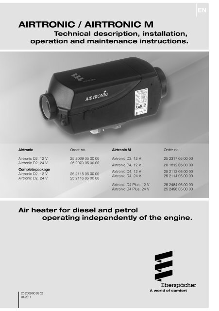
<strong>AIRTRONIC</strong> / <strong>AIRTRONIC</strong> M<br />
Technical description, installation,<br />
operation and maintenance instructions.<br />
Airtronic Order no.<br />
Airtronic D2, 12 V 25 2069 05 00 00<br />
Airtronic D2, 24 V<br />
Complete package<br />
25 2070 05 00 00<br />
Airtronic D2, 12 V 25 2115 05 00 00<br />
Airtronic D2, 24 V 25 2116 05 00 00<br />
Airtronic M Order no.<br />
Airtronic D3, 12 V 25 2317 05 00 00<br />
Airtronic B4, 12 V 20 1812 05 00 00<br />
Airtronic D4, 12 V 25 2113 05 00 00<br />
Airtronic D4, 24 V 25 2114 05 00 00<br />
Airtronic D4 Plus, 12 V 25 2484 05 00 00<br />
Airtronic D4 Plus, 24 V 25 2498 05 00 00<br />
Air heater for diesel and petrol<br />
operating independently of the engine.<br />
25 2069 90 99 52<br />
01.2011
2<br />
1<br />
Contents<br />
1<br />
2<br />
3<br />
4<br />
5<br />
6<br />
7<br />
8<br />
Introduction<br />
Chapter Title Contents Page<br />
Introduction • Contents ................................................................................................ 2<br />
• Concept of this manual .......................................................................... 3<br />
• Special text structure, presentation and picture symbols ....................... 4<br />
• Important information before starting work ............................................. 4<br />
• Statutory regulations .......................................................................... 5, 6<br />
• Safety instructions for installation and operation ................................... 7<br />
• Accident prevention ............................................................................... 7<br />
Product information • Scope of supply: heater, universal installation kit<br />
and complete packages ..................................................................... 8, 9<br />
• Scope of supply: heater and “Plus” installation kit .......................... 10, 11<br />
• Technical data Airtronic D2 .................................................................. 12<br />
• Technical data Airtronic D3, D4, D4 Plus ............................................. 13<br />
• Technical data Airtronic B4 .................................................................. 14<br />
• Main dimensions ................................................................................... 15<br />
Installation • Installation and location ....................................................................... 16<br />
• Installing the 24 V heater in a vehicle for the transport<br />
of dangerous goods .............................................................................. 17<br />
• Installation location ........................................................................ 16, 17<br />
• Possible installation positions ............................................................... 18<br />
• Cable harness connection, right or left ................................................. 18<br />
• Mounting and fastening ........................................................................ 19<br />
• Nameplate ............................................................................................ 20<br />
• Heater air system ................................................................................. 21<br />
• Exhaust system ..................................................................................... 22<br />
• Combustion air system .......................................................................... 23<br />
• Fuel supply ................................................................................... 24 – 28<br />
Operation and • Operating instructions / important information for operation ................. 29<br />
function • Initial commissioning ............................................................................. 29<br />
• Description of functions ........................................................................ 30<br />
• Control and safety devices / EMERGENCY OFF .................................... 31<br />
Electrical system • Heater wiring ....................................................................................... 32<br />
• Parts list for the circuit diagrams / Circuit diagrams ..................... 33 – 45<br />
Troubleshooting • In case of faults, please check the following points .............................. 46<br />
Maintenance • Troubleshooting .................................................................................... 46<br />
Service • Maintenance instructions ..................................................................... 46<br />
• Service ................................................................................................. 46<br />
Environment • Certification .......................................................................................... 47<br />
• Disposal ................................................................................................ 47<br />
• EU Declaration of Conformity ................................................................ 47<br />
Lists • List of key words ............................................................................ 48, 49<br />
• List of abbreviations ............................................................................. 49
1<br />
Introduction<br />
Concept of this manual<br />
This manual aims to support the service company<br />
installing the heater and to provide the user with all<br />
important information about the heater.<br />
The manual has been divided into 8 chapters to make<br />
it easier to find the corresponding information quickly.<br />
1<br />
2<br />
3<br />
Introduction<br />
Here you will find important introductory<br />
information about installation of the heater<br />
and about the structure of the manual.<br />
Product information<br />
Here you will find information about the scope<br />
of supply, the technical data and the<br />
dimensions of the heater.<br />
Installation<br />
Here you will find important information and<br />
instructions referring to installation of the<br />
heater.<br />
4 8<br />
Operation and function<br />
Here you will find information about the<br />
operation and function of the heater.<br />
5<br />
6<br />
7<br />
Electric system<br />
Here you will find information about the<br />
electronic system and electronic components<br />
of the heater.<br />
Troubleshooting / maintenance / service<br />
This section contains information on possible<br />
faults and malfunctions, troubleshooting,<br />
maintenance and the service hotline.<br />
Environment<br />
Here you will find information about certification<br />
and disposal of the heater together with the EU<br />
Declaration of Conformity.<br />
Lists<br />
Here you will find the key word list and<br />
abbreviations list.<br />
3
4<br />
1<br />
Introduction<br />
Special text structure, presentation<br />
and picture symbols<br />
This manual uses special text structures and picture<br />
symbols to emphasise different contents.<br />
Please refer to the examples below for the<br />
corresponding meanings and associated actions.<br />
Special structure and presentations<br />
A dot (•) indicates a list which is started by a<br />
heading. If an indented dash (–) follows a dot, this list<br />
is subordinate to the dot.<br />
Picture symbols<br />
Regulation!<br />
This picture symbol with the remark “Regulation”<br />
refers to a statutory regulation. Failure to comply with<br />
this regulation results in expiry of the type permit for<br />
the heater and preclusion of any guarantee and<br />
liability claims on J. Eberspächer GmbH & Co. KG and<br />
its associated companies.<br />
Danger!<br />
This picture symbol with the remark “Danger!” refers<br />
to the risk of a fatal danger to life and limb. Under<br />
certain circumstances, failure to comply with these<br />
instructions can result in severe or life-threatening<br />
injuries.<br />
Caution!<br />
This picture symbol with the remark “Caution!” refers<br />
to a dangerous situation for a person and / or the<br />
product.<br />
Failure to comply with these instructions can result in<br />
injuries to people and / or damage to machinery.<br />
Please note!<br />
These remarks contain application recommendations<br />
and useful tips for installation of the heater.<br />
Important information before<br />
starting work<br />
Range of application of the heater<br />
The air heater operating independently of an engine is<br />
intended for installation in the following vehicles,<br />
depending on its heating output:<br />
Vehicles of all kinds (max 9 seats)<br />
Construction machinery<br />
Agricultural machinery<br />
Boats, ships and yachts (only diesel heaters)<br />
Camper vans<br />
Please note!<br />
• The heaters (only diesel heaters, 24 volt) can be installed<br />
in vehicles used for the transport of dangerous<br />
goods as per ADR.<br />
The current controller is to be replaced by a special<br />
controller when the heater is to be used to heat<br />
the freight compartment / cargo (order no. see heater<br />
price list or spare parts list).<br />
The "Plus" installation kits are intended for installation<br />
in a camper van.<br />
Purpose of the heater<br />
Pre-heating, de-misting windows<br />
Heating and keeping the following warm:<br />
– Driver and working cabs, Ship’s cabins<br />
– Freight compartments<br />
– Passenger and crew compartments<br />
– Camper vans<br />
On account of its functional purpose, the heater is not<br />
permitted for the following applications:<br />
• Long-term continuous operation, e.g. for preheating<br />
and heating of:<br />
– Residential rooms<br />
– Garages<br />
– Work huts, weekend homes and hunting huts<br />
– Houseboats, etc.<br />
Heating or drying:<br />
– Living creatures (people or animals) by blowing hot<br />
air directly at the subject<br />
– Objects<br />
– Blowing hot air into containers<br />
Caution!<br />
Safety instructions for application and<br />
proper purpose<br />
The heater must only be used and operated for the<br />
range of application stated by the manufacturer in<br />
compliance with the “Operating instructions”<br />
included with every heater.
1<br />
Introduction<br />
Statutory regulations<br />
The Federal Road Transport Directorate has issued<br />
an "EC type approval" and an "EMC type approval"<br />
for the heater for installation in motor vehicles and<br />
with the following official type approval marks, noted<br />
on the heater name plate.<br />
Airtronic EC- e1 00 0025<br />
EMC- e1 031516<br />
Airtronic M EC- e1 00 0026<br />
EMC- e1 031653<br />
Statutory Regulations!<br />
Directive 2001 / 56 / EU of the European<br />
Parliament and the Council<br />
• Arrangement of the heater<br />
– Parts of the structure and other components near<br />
the heater must be protected from excess heat<br />
exposure and possible contamination from fuel or<br />
oil.<br />
– The heater must not pose a fire hazard even when<br />
it overheats.<br />
This requirement is deemed to be fulfilled when<br />
adequate clearance to all parts is observed during<br />
installation, sufficient ventilation is provided and<br />
fire-proof materials or heat plates are used.<br />
– The heater must not be mounted in the passenger<br />
compartment of vehicles in class M 2 and M 3 .<br />
But a heater in a hermetically sealed enclosure<br />
which otherwise complies with the conditions<br />
stated above may be used.<br />
– The factory nameplate or duplicate must be affixed<br />
so that it can still be easily read when the heater<br />
is installed in the vehicle.<br />
– All appropriate precautions must be taken when<br />
arranging the heater to minimise the risk of injuries<br />
to persons or damage to other property.<br />
Operating status display<br />
– A clearly visible operating display in the user’s<br />
field of vision must indicate when the heater is<br />
switched on and off.<br />
Fuel supply<br />
– The fuel intake connection must not be located in<br />
the passenger compartment and must be sealed<br />
with a properly closing lid to prevent any fuel leaks.<br />
– In heaters for liquid fuel where the heater fuel is<br />
separate from the vehicle fuel, the type of fuel and<br />
intake connection must be clearly identified.<br />
– A warning sign is to be fixed to the intake<br />
connection indicating that the heater must be<br />
switched off before refuelling.<br />
Exhaust system<br />
– The exhaust outlet must be arranged so as to<br />
prevent any penetration of exhaust fumes into the<br />
vehicle interior through the ventilation system,<br />
warm air intakes or open windows.<br />
Combustion air intake<br />
– The air for the heater combustion chamber must<br />
not be sucked in from the passenger compartment<br />
of the vehicle.<br />
– The air intake must be arranged or protected in<br />
such a way that it cannot be blocked by other<br />
objects.<br />
Heater air intake<br />
– The heater air supply must consist of fresh air or<br />
circulated air and be sucked in from a clean area<br />
not contaminated by exhaust fumes of the drive<br />
machine, the combustion heater or any other<br />
source in the vehicle.<br />
– The intake pipe must be protected by a grid or<br />
other suitable means.<br />
Hot air outlet<br />
– The hot air pipes within the vehicle must be<br />
arranged or protected in such a way that there is<br />
no risk of injury or damage if they are touched.<br />
– The air outlet must be arranged or protected in<br />
such a way that it cannot be blocked by any<br />
objects.<br />
Statutory Regulations!<br />
Mounting the heater in a vehicle for the transport of<br />
dangerous goods as per ADR<br />
When the heater is to be installed in vehicles for the<br />
transport of dangerous goods, the regulations of<br />
ADR must also be observed (see page 6).<br />
5
6<br />
1<br />
Introduction<br />
Statutory Regulations!<br />
Additional regulations for certain vehicles named in<br />
Directive 94 / 55 / EC (ADR Framework Directive)<br />
Scope<br />
This appendix applies to vehicles for which the special<br />
provisions of Directive 94 / 55 / EC apply to<br />
combustion heaters and their installation.<br />
Definition of terms used<br />
For the purposes of this appendix, the vehicle<br />
designations "EX / II", "EX / III", "AT", "FL" and "OX"<br />
according to Chapter 9.1 of Annex B of Directive 94 /<br />
55 / EC are used.<br />
Technical regulations<br />
General provisions (EX / II, EX / III, AT, FL and OX<br />
vehicles)<br />
Avoid heating and ignition<br />
The combustion heaters and their exhaust gas routing<br />
shall be designed, located, protected or covered so<br />
as to prevent any unacceptable risk of heating or<br />
ignition of the load. This requirement shall be<br />
considered as fulfilled if the fuel tank and the exhaust<br />
system of the appliance conform to provisions in<br />
3.1.1.1 and 3.1.1.2. Compliance with these<br />
regulations shall be checked in the complete vehicle.<br />
Fuel tanks<br />
Fuel tanks for supplying the heater shall conform to<br />
the following regulations:<br />
• In the event of any leakage, the fuel shall drain to<br />
the ground without coming into contact with hot<br />
parts of the vehicle or the load;<br />
• fuel tanks containing petrol shall be equipped with<br />
an effective flame trap at the filler opening or with a<br />
closure enabling the opening to be kept<br />
hermetically sealed.<br />
Exhaust system and exhaust pipe layout<br />
The exhaust system as well as the exhaust pipes shall<br />
laid out or protected to avoid any danger to the load<br />
through heating or ignition. Parts of the exhaust<br />
system situated directly below the fuel tank (diesel)<br />
shall have a clearance of at least 100 mm or be<br />
protected by a thermal shield.<br />
Switching on the combustion heater<br />
The combustion heater may only be switched on<br />
manually. Automatic switching on via a programmable<br />
switch is not permitted.<br />
EX / II and EX / III vehicles<br />
Combustion heaters for gaseous fuels are not<br />
permitted.<br />
FL vehicles<br />
Combustion heaters must be able to be taken out of<br />
service/disabled at least by the methods described in<br />
the following:<br />
a) Switching off manually in the driver's cabin<br />
b) Switching off the vehicle's engine; in this case the<br />
heater may be manually switched back on by the<br />
vehicle driver;<br />
c) Starting up of a feed pump installed in the vehicle<br />
for the dangerous goods carried.<br />
Combustion heater after-run<br />
After-running of the switched off combustion heater is<br />
permitted. In the cases named in the "FL vehicles"<br />
paragraph under letters b) and c) the supply of<br />
combustion air must be interrupted by suitable means<br />
after a maximum after-run period of 40 seconds. Only<br />
combustion heaters whose heat exchangers are<br />
verifiably not damaged by the reduced after-run period<br />
of 40 seconds beyond their usual use period may be<br />
used.<br />
Please note!<br />
• Compliance with the statutory regulations, the<br />
additional regulations and safety instructions is<br />
prerequisite for guarantee and liability claims.<br />
Failure to comply with the statutory regulations and<br />
safety instructions and incorrect repairs even when<br />
using original spare parts make the guarantee null<br />
and void and preclude any liability for<br />
J. Eberspächer GmbH & Co. KG.<br />
• Subsequent installation of this heater must comply<br />
with these installation instructions.<br />
The statutory regulations are binding and must also<br />
be observed in countries which do not have any<br />
special regulations.<br />
When the heater is to be installed in vehicles not<br />
subject to the German Ordinance for the Registration<br />
of Motor Vehicles (StVZO), for example<br />
ships, the specially valid regulations and<br />
installation instructions for these special<br />
applications must be observed.<br />
• Installation of the heater in special vehicles must<br />
comply with the regulations applying to such<br />
vehicles.<br />
• Other installation requirements are contained in the<br />
corresponding sections of this manual.
1<br />
Introduction<br />
Safety instructions for installation<br />
and operation<br />
Danger!<br />
Risk of injury, fire and poisoning!<br />
• The heater must only be started up when the<br />
maintenance flap is closed and the outlet hood is<br />
mounted in position.<br />
• The maintenance flap must not be opened during<br />
operation.<br />
• Disconnect the vehicle battery before commencing<br />
any kind of work.<br />
• Before working on the heater, switch the heater off<br />
and let all hot parts cool down.<br />
• The heater must not be operated in closed rooms,<br />
e.g. in the garage or in a multi-storey car park.<br />
• Adjustable hot air outlets must always be adjusted<br />
so that they cannot blow hot air directly at living<br />
creatures (people, animals) or objects sensitive to<br />
temperature (loose and / or fastened).<br />
Caution!<br />
Safety instructions for installation and operation!<br />
• The year of initial commissioning must be marked on<br />
the nameplate.<br />
• The heat exchanger of air heaters is a component<br />
subject to high thermal loads which must be<br />
replaced 10 years after initial commissioning of the<br />
heater. In addition, the installation date must be<br />
entered on the plate “original spare part” enclosed<br />
with the heat exchanger must. Then affix the plate<br />
next to the nameplate on the heater.<br />
• The heater must only be installed by a JE partner<br />
authorised by the manufacturer according to the<br />
instructions in this manual and possibly according to<br />
special installation recommendations; the same<br />
applies to any repairs to be carried out in the case<br />
or repairs or guarantee claims.<br />
• Only the control elements approved by<br />
J. Eberspächer GmbH & Co. KG must be used to<br />
operate the heater. The use of other control<br />
elements can cause malfunctions.<br />
• Repairs by unauthorised third-parties or with not<br />
original spare parts are dangerous and therefore not<br />
allowed. They result in expiry of the type permit of<br />
the heater; consequently, when installed in motor<br />
vehicles they can cause expiry of the vehicle<br />
operating licence.<br />
• The following measures are not allowed:<br />
– Changes to components relevant to the heater.<br />
– Use of third-party components not approved by<br />
Eberspächer.<br />
– Nonconformities in installation or operation from<br />
the statutory regulations, safety instructions or<br />
specifications relevant to safe operation as stated<br />
in the installation instructions and operating<br />
instructions. This applies in particular to the<br />
electrical wiring, fuel supply, combustion air<br />
system and exhaust system.<br />
• Only original accessories and original spare parts<br />
must be used during installation or repairs.<br />
• When carrying out electric welding on the vehicle,<br />
the plus pole cable at the battery should be<br />
disconnected and placed at ground to protect the<br />
controller.<br />
• The heater must not be operated where there is a<br />
risk of an accumulation of flammable vapours or<br />
dust, for example close to<br />
– fuel depot<br />
– coal depot<br />
– wood depot<br />
– grain depots etc.<br />
• The heater must be switched off when refuelling.<br />
• When the heater is mounted in a safety housing<br />
etc., the installation compartment of the heater is<br />
not a stowage compartment and must be kept clear.<br />
In particular fuel canisters, oil cans, spray cans,<br />
gas cartridges, fire extinguishers, cleaning rags,<br />
items of clothing, paper etc. must not be stored or<br />
transported on or next to the heater.<br />
• Defect fuses must only be replaced by fuses with<br />
the prescribed rating.<br />
• If fuel leaks from the heater fuel system, arrange<br />
for the damage to be repaired immediately by a JE<br />
service partner.<br />
• After-running of the heater must not be interrupted<br />
prematurely e.g. by pressing the battery<br />
disconnecting switch, apart from in the case of an<br />
emergency stop.<br />
Accident prevention<br />
General accident prevention regulations and the<br />
corresponding workshop and operation safety<br />
instructions are to be observed.<br />
7
8<br />
2<br />
Product information<br />
Heater scope of supply, complete<br />
packages and universal installation kit<br />
Heater Order No.<br />
Airtronic D2, 12 V 25 2069 05 00 00<br />
Airtronic D2, 24 V 25 2070 05 00 00<br />
Airtronic D3, 12 V 25 2317 05 00 00<br />
Airtronic B4, 12 V 20 1812 05 00 00<br />
Airtronic D4, 12 V 25 2113 05 00 00<br />
Airtronic D4, 24 V 25 2114 05 00 00<br />
Airtronic D4 Plus, 12 V 25 2484 05 00 00<br />
Airtronic D4 Plus, 24 V<br />
The scope of supply includes:<br />
No. in<br />
25 2498 05 00 00<br />
figure Name<br />
1 Heater<br />
2 Metering pump<br />
Complete package Order No.<br />
Airtronic D2, 12 V<br />
Complete package 25 2115 05 00 00<br />
Airtronic D2, 24 V<br />
Complete package 25 2116 05 00 00<br />
Included in the scope of supply:<br />
No. in<br />
figure Name<br />
1 Heater<br />
2 Metering pump<br />
– Installation kit with outlet hood Ø 60 mm<br />
3 Minicontroller<br />
4 Tank connection (only in complete package<br />
25 2116 05 00 00)<br />
Universal installation kit (all versions)<br />
Included in the scope of supply:<br />
No. in<br />
figure Name<br />
5 Lead harness, plus / minus<br />
6 Lead harness, operation<br />
7 Flexible exhaust pipe<br />
8 Combustion air hose<br />
9 Cable tie<br />
10 Bracket, dosing pump<br />
11 Pipe, 6 x 2<br />
12 Pipe, 4 x 1.25<br />
13 Hose clip (2x)<br />
14 Air outlet, rotatable<br />
15 Grid<br />
16 Hood<br />
17 Flexible pipe<br />
18 Exhaust silencer<br />
19 Cable harness, heater<br />
Using the universal installation kits<br />
Order No.<br />
Universal installation kit 25 2069 80 00 00<br />
• with outlet hood Ø 60 mm,<br />
heater guide number 6, usable with:<br />
– Airtronic D2, 12 V 25 2069 05 00 00<br />
– Airtronic D2, 24 V 25 2070 05 00 00<br />
Universal installation kit<br />
• with outlet hood Ø 90 mm,<br />
25 2113 80 00 00<br />
heater guide number 10, usable with:<br />
– Airtronic D3, 12 V 25 2317 05 00 00<br />
– Airtronic B4, 12 V 20 1812 05 00 00<br />
– Airtronic D4, 12 V 25 2113 05 00 00<br />
– Airtronic D4, 24 V<br />
• with outlet hood Ø 90 mm,<br />
25 2114 05 00 00<br />
heater guide number 15, usable with:<br />
– Airtronic D4 Plus, 12 V 25 2484 05 00 00<br />
– Airtronic D4 Plus, 24 V 25 2498 05 00 00<br />
Universal installation kit<br />
• with outlet hood Ø 75 mm,<br />
25 2144 80 00 00<br />
heater guide number 3, usable with:<br />
– Airtronic D3, 12 V 25 2317 05 00 00<br />
– Airtronic B4, 12 V 20 1812 05 00 00<br />
– Airtronic D4, 12 V 25 2113 05 00 00<br />
– Airtronic D4, 24 V 25 2114 05 00 00<br />
• with outlet hood Ø 75 mm,<br />
heater guide number 8, for recirculation mode<br />
heater guide number 10, for fresh air mode<br />
usable with:<br />
– Airtronic D4 Plus, 12 V 25 2484 05 00 00<br />
– Airtronic D4 Plus, 24 V 25 2498 05 00 00<br />
Please note!<br />
• For controls, please refer to the price list or<br />
accessories catalogue.<br />
• Parts without a figure no. are small parts and packed<br />
in a bag.<br />
• Please consult the additional parts catalogue if any<br />
other parts are required for installation.<br />
• For notes on the units' guide numbers, please refer to<br />
additional parts catalogue.
2<br />
Product information<br />
Scope of supply: Heater, universal installation kit and complete packages<br />
* Only in complete package Airtronic D2<br />
** Only for Airtronic D3, B4, D4, D4 Plus<br />
*** Only for Airtronic D2<br />
**** Only in complete package Airtronic D2, 24 volt<br />
9
2<br />
Scope of supply<br />
Heater and “Plus” installation kit<br />
Heater Order No.<br />
10<br />
Product information<br />
Airtronic D2, 12 V 25 2069 05 00 00<br />
Airtronic D2, 24 V 25 2070 05 00 00<br />
Airtronic D3, 12 V 25 2317 05 00 00<br />
Airtronic B4, 12 V 20 1812 05 00 00<br />
Airtronic D4, 12 V 25 2113 05 00 00<br />
Airtronic D4, 24 V 25 2114 05 00 00<br />
Airtronic D4 Plus, 12 V 25 2484 05 00 00<br />
Airtronic D4 Plus, 24 V<br />
The scope of supply includes:<br />
No. in<br />
25 2498 05 00 00<br />
figure Name<br />
1 Heater<br />
2 Metering pump<br />
“Plus” installation kit (all versions)<br />
The scope of supply includes:<br />
No. in<br />
figure Name<br />
3 Combustion air intake silencer<br />
4 Exhaust silencer<br />
5 Hose connecting sockets<br />
6 Grid<br />
7 Y branch<br />
8 Tank connection kit<br />
9 Temperature control sensor<br />
10 Cable loom for temperature control sensor<br />
11 EasyStart T timer<br />
12 Lead harness, plus / minus<br />
13 Lead harness, operation<br />
14 Hose clip (2x)<br />
15 Hose clip (6x)<br />
16 Pipe 4 x 1.25 (included in Item 8)<br />
17 Cable harness, heater<br />
18 Flexible exhaust pipe<br />
19 Grid<br />
20 Bracket metering pump<br />
21 Cable tie (2 sets)<br />
22 Hood<br />
23 Outlet (2x)<br />
24 Adapter Ø 6 / 4<br />
25 Pipe 4 x 1 (included in Item 8)<br />
26 Pipe clip, Ø 50 mm<br />
27 Flexible pipe for hot air system<br />
Using the “Plus” installation kits<br />
Order No.<br />
“Plus” installation kit 25 2069 81 00 00<br />
• with outlet hood Ø 75 mm,<br />
heater guide number 12, usable with:<br />
– Airtronic D2, 12 V 25 2069 05 00 00<br />
– Airtronic D2, 24 V 25 2070 05 00 00<br />
“Plus” installation kit<br />
• with outlet hood Ø 90 mm,<br />
25 2113 81 00 00<br />
heater guide number 10, usable with:<br />
– Airtronic D3, 12 V 25 2317 05 00 00<br />
– Airtronic B4, 12 V 20 1812 05 00 00<br />
– Airtronic D4, 12 V 25 2113 05 00 00<br />
– Airtronic D4, 24 V<br />
• with outlet hood Ø 90 mm,<br />
25 2114 05 00 00<br />
heater guide number 15, usable with:<br />
– Airtronic D4 Plus, 12 V 25 2484 05 00 00<br />
– Airtronic D4 Plus, 24 V 25 2498 05 00 00<br />
“Plus” installation kit 25 2484 81 00 00<br />
• with outlet hood Ø 75 mm,<br />
heater guide number 8, for recirculation mode<br />
heater guide number 10, for fresh air mode<br />
usable with:<br />
– Airtronic D4 Plus, 12 V 25 2484 05 00 00<br />
– Airtronic D4 Plus, 24 V 25 2498 05 00 00<br />
Please note!<br />
• For controls, please refer to the price list or<br />
accessories catalogue.<br />
• Parts without a figure no. are small parts and packed<br />
in a bag.<br />
• Please consult the additional parts catalogue if any<br />
other parts are required for installation.<br />
• For notes on the units' guide numbers, please refer to<br />
additional parts catalogue.<br />
• The “Plus” installation kits are particularly suitable for<br />
installations in camper vans and boats.
2<br />
Product information<br />
Scope of supply: Heater and “Plus” installation kit<br />
11
2<br />
12<br />
Product information<br />
Technichal data<br />
Heater type<br />
Heater<br />
Version<br />
Heating medium<br />
Control of the heat flow<br />
Heat flow (watt)<br />
Heater air flow rate with hood Ø 60 mm<br />
without counterpressure (kg/h)<br />
Fuel consumption (l/h)<br />
Elektr. power consumption (watt)<br />
in operation (12 and 24 volt)<br />
at start (12 and 24 volt)<br />
Rated voltage<br />
Operating range<br />
Lower voltage limit:<br />
An undervoltage protection in the controller<br />
switches off the heater when the voltage<br />
limit is reached.<br />
Upper voltage limit:<br />
An uppervoltage protection in the controller<br />
switches off the heater when the voltage<br />
limit is reached.<br />
Fuel<br />
“Fuel quality“ and “Fuel at low temperatures“<br />
see page 28.<br />
Tolarable ambient temperature<br />
Heater<br />
Dosing pump<br />
Maximum air intake temperature<br />
Interference suppression<br />
Weight<br />
Ventilation mode<br />
Caution!<br />
Safety instructions for technical data!<br />
Failure to comply with the technical data<br />
can result in malfunctions.<br />
Airtronic<br />
Airtronic D2<br />
D2<br />
Air<br />
Stage<br />
Power Large Medium Small Off<br />
2200 1800 1200 850 –<br />
105 90 60 40 13<br />
0.28 0.23 0.15 0.10 –<br />
34 22 12 8 5<br />
100<br />
12 or 24 volt<br />
approx. 10.5 volt resp. 21 volt<br />
Undervoltage protection trigger time: 20 seconds<br />
approx. 16 volt resp. 32 volt<br />
Overvoltage protection trigger time: 20 seconds<br />
Commercially available diesel fuel (DIN EN 590)<br />
Operation Not running<br />
–40 °C to +70 °C –40 °C to +85 °C<br />
–40 °C to +50 °C –40 °C to +125 °C<br />
+40 °C<br />
Interference suppression class 5 to DIN EN 55 025<br />
approx. 2.7 kg<br />
possible<br />
Please note!<br />
Provided no limit values are given, the technical data<br />
listed is subject to the tolerances usually applicable<br />
to heaters of ±10% for nominal voltage, ambient<br />
temperature 20 °C and reference altitude Esslingen.
2<br />
Product information<br />
Technichal data<br />
Heatertyp<br />
Heater<br />
Version<br />
Heating medium<br />
Control of the heat flow<br />
Heat flow (watt) D3<br />
D4<br />
D4 Plus<br />
Heater air flow rate D3 with hood Ø 90 mm<br />
without counter- D4 with hood Ø 90 mm<br />
pressure (kg/h) D4 Plus with hood Ø 75 mm<br />
Fuel consumption (l/h) D3<br />
D4<br />
D4 Plus<br />
Elektr. power consumption (watt) D3<br />
in operation (12 and 24 volt) D4<br />
D4 Plus<br />
at start (12 and 24 volt)<br />
Rated voltage<br />
Operating range<br />
Lower voltage limit:<br />
An undervoltage protection in the controller<br />
switches off the heater when the voltage<br />
limit is reached.<br />
Upper voltage limit:<br />
An uppervoltage protection in the controller<br />
switches off the heater when the voltage<br />
limit is reached.<br />
Fuel<br />
“Fuel quality“ and “Fuel at low temperatures“<br />
see page 28.<br />
Tolarable ambient temperature<br />
Heater<br />
Dosing pump<br />
Maximum air intake temperature<br />
Interference suppression<br />
Weight<br />
Ventilation mode<br />
Please note!<br />
Safety instructions for technical data and see page 12.<br />
Airtronic M<br />
Airtronic D3 / Airtronic D4 / Airtronic D4 Plus<br />
D3 / D4 / D4 Plus<br />
Air<br />
Stage<br />
Power Large Medium Small Off<br />
3000 2200 1600 900 –<br />
4000 3000 2000 900 –<br />
4000 3000 2000 900 –<br />
150 120 90 60 24<br />
185 150 110 60 24<br />
175 140 100 55 22<br />
0.38 0.28 0.2 0.11 –<br />
0.51 0.38 0.25 0.11 –<br />
0.51 0.38 0.25 0.11 –<br />
24 16 10 7 5<br />
40 24 13 7 5<br />
55 30 16 7 5<br />
100<br />
12 or 24 volt<br />
approx. 10.5 volt resp. 21 volt<br />
Undervoltage protection trigger time: 20 seconds<br />
approx. 16 volt resp. 32 volt<br />
Overvoltage protection trigger time: 20 seconds<br />
Commercially available diesel fuel (DIN EN 590)<br />
Operation Not running<br />
–40 °C to +70 °C –40 °C to +85 °C<br />
–40 °C to +50 °C –40 °C to +125 °C<br />
+40 °C<br />
Interference suppression class 5 to DIN EN 55 025<br />
approx. 4.5 kg<br />
possible<br />
13
2<br />
14<br />
Product information<br />
Technichal data<br />
Heatertyp<br />
Heater<br />
Version<br />
Heating medium<br />
Control of the heat flow<br />
Heat flow (watt)<br />
Heater air flow rate with hood Ø 90 mm<br />
without counterpressure (kg/h)<br />
Fuel consumption (l/h)<br />
Elektr. power consumption (watt)<br />
in operation (12 volt)<br />
at start (12 volt)<br />
Rated voltage<br />
Operating range<br />
Lower voltage limit:<br />
An undervoltage protection in the controller<br />
switches off the heater when the voltage<br />
limit is reached.<br />
Upper voltage limit:<br />
An uppervoltage protection in the controller<br />
switches off the heater when the voltage<br />
limit is reached.<br />
Fuel<br />
“Fuel quality“ and “Fuel at low temperatures“<br />
see page 28.<br />
Tolarable ambiet temperature<br />
Heater<br />
Dosing pump<br />
Maximum air intake temperature<br />
Interference suppression<br />
Weight<br />
Ventilation mode<br />
Caution!<br />
Safety instructions for technical data!<br />
Failure to comply with the technical data<br />
can result in malfunctions.<br />
Airtronic M<br />
Airtronic B4<br />
B4<br />
Air<br />
Stage<br />
Power Large Medium Small Off<br />
3800 3200 2100 1300 –<br />
185 160 120 85 24<br />
0.54 0.46 0.29 0.18 –<br />
40 29 15 9 5<br />
100<br />
12 volt<br />
approx. 10.5 volt<br />
Undervoltage protection trigger time: 20 seconds<br />
approx. 16 volt<br />
Undervoltage protection trigger time: 20 seconds<br />
Commercially available petrol fuel (DIN EN 228)<br />
Operation Not running<br />
–40 °C to +50 °C –40 °C to +85 °C<br />
–40 °C to +20 °C –40 °C to +125 °C<br />
+40 °C<br />
Interference suppression class 5 to DIN EN 55 025<br />
approx. 4.5 kg<br />
possible<br />
Please note!<br />
Provided no limit values are given, the technical data<br />
listed is subject to the tolerances usually applicable<br />
to heaters of ±10% for nominal voltage, ambient<br />
temperature 20 °C and reference altitude Esslingen.
2<br />
Product information<br />
Main dimensions Airtronic<br />
Main dimensions Airtronic M<br />
1 Minimum installation clearance (space) for opening the lid and for<br />
dismantling the glow plug and the controller.<br />
2 Minimum installation clearance (space) for intake of heater air.<br />
* Outlet hood for Airtronic D2:<br />
- Ø 60 mm, included in the universal installation kit<br />
- Ø 75 mm, included in the “Plus” installation kit<br />
** Outlet hood for Airtronic D3, B4, D4:<br />
- Ø 75 mm, included in the universal installation kit<br />
- Ø 90 mm, included in the universal installation kit or in<br />
the “Plus” installation kit<br />
Outlet hood for Airtronic D4 Plus:<br />
- Ø 75 mm, included in the universal installation kit or in<br />
the “Plus” installation kit<br />
- Ø 90 mm, included in the universal installation kit or in<br />
the “Plus” installation kit<br />
*<br />
**<br />
Please note!<br />
A = Exhaust<br />
B = Fuel<br />
V = Combustion air<br />
Installation of spherical reduction hood is not<br />
permitted in the Airtronic D4 Plus.<br />
15
3<br />
Installation and location<br />
The heater is suitable and certified for installation in<br />
parts of vehicles used by persons.<br />
Installation in the cab or passenger compartments of<br />
coaches or buses with more than 9 seats is not<br />
allowed.<br />
When installing in compartments used by persons, the<br />
exhaust, combustion air and fuel pipes in these areas<br />
must not have any detachable connections and must<br />
be routed splash-waterproof in the breakthroughs. For<br />
this reason, the heater can be mounted with its foot<br />
using the flange seal in the foot to the vehicle floor or<br />
to an outer wall of the vehicle.<br />
The electronic control is integrated in the heater which<br />
makes wiring during installation much easier.<br />
16<br />
Installation<br />
Please note!<br />
When installing the heater, always make sure there<br />
is sufficient clearance left for intake of the heater air<br />
and for dismantling the glow plug and controller (see<br />
page 15 “main dimensions“).<br />
The regulations and safety instructions to be<br />
observed for this chapter are on page 4 – 7.<br />
Installation position<br />
Installation position in a camper van<br />
In a camper van, the heater is preferably installed in<br />
the inner compartment or luggage compartment.<br />
If it is not possible to install the heater in the<br />
passenger compartment or boot, the heater can also<br />
be mounted, protected against splashing water,<br />
under the vehicle floor.<br />
Please note!<br />
The "Plus" installation kits are intended for<br />
installation in a camper van.<br />
Installing the diesel heater 24 V in a vehicle<br />
for the transport of dangerous goods as per<br />
ADR<br />
The 24 Volt diesel heater can be installed in vehicles<br />
used for the transport of dangerous goods as per ADR.<br />
The heater fulfils the regulations of ADR with the<br />
corresponding electrical wiring, see circuit diagrams at<br />
the end of this manual.<br />
For information about the ADR regulations, please refer<br />
to page 6, 31 and to the information leaflet no.<br />
25 2161 95 15 80.<br />
Please note!<br />
For installation of the heater in vehicles for the<br />
transport of dangerous goods, the regulations of<br />
ADR must be observed.<br />
1 Heater in front of the passenger seat<br />
2 Heater between the driver’s seat and the<br />
passenger seat<br />
3 Heater under the vehicle floor<br />
4 Heater under the back seat<br />
5 Heater in the boot
3<br />
3<br />
Installation<br />
Installation<br />
Installation in a car or people carrier<br />
In a car or people carrier, the heater is preferably<br />
installed in the passenger compartment or boot.<br />
If it is not possible to install the heater in the<br />
passenger compartment or boot, the heater can also<br />
be mounted, protected against splashing water,<br />
under the vehicle floor.<br />
1 Heater in front of the passenger seat<br />
2 Heater between the driver’s seat and the<br />
passenger seat<br />
3 Heater under the vehicle floor<br />
4 Heater under the back seat<br />
5 Heater in the boot<br />
Installation in an excavator cab (only diesel heaters)<br />
In an excavator, the heater is preferably installed in<br />
the cab. If it is not possible to install the heater in the<br />
cab, the heater can also be installed in a storage box<br />
outside the cab.<br />
1 Heater in the seat box<br />
2 Heater on the cab rear wall<br />
3 Heater in a protective case<br />
Installation in a truck (only diesel heaters)<br />
In a truck, the heater is preferably installed inside the<br />
driver’s cab. If it is not possible to install the heater<br />
inside the driver’s cab, it can also be mounted in the<br />
tool box or in a storage box.<br />
1 Heater in the passenger’s foot room<br />
2 Heater on the cab rear wall<br />
3 Heater under the bed<br />
4 Heater in the tool box<br />
Please note!<br />
The installation suggestions made in the<br />
installation instructions are just examples. Other<br />
installation locations are possible, as long as they<br />
correspond to the installation requirements stated<br />
in these instructions.<br />
Other installation information (e.g. for boats and<br />
ships) is available from the manufacturer on<br />
request.<br />
Observe the tolerable installation position together<br />
with the operating and storage temperatures.<br />
17
3<br />
Possible installation positions<br />
The heater is preferably installed in the normal<br />
position as shown in the drawing.<br />
Depending on the installation conditions, the heater<br />
can be tilted by max. 30° (flow direction to the bottom)<br />
or turned by max. 90° around its own longitudinal axis<br />
(exhaust connection horizontal, glow plug points<br />
upwards!).<br />
Normal position horizontal (exhaust connection<br />
downwards) with tolerable swivel range<br />
1 Heater air intake opening (fan wheel)<br />
2 Position of the glow plug<br />
3 Direction of flow<br />
Cable harness connection, right or left<br />
If necessary, the cable harness connection can be<br />
changed over to the other side of the heater. To do<br />
so, the controller has to be removed and the lower<br />
semi-circular cable harness cover unclipped.<br />
The cable harness can then be rerouted in the<br />
controller.<br />
Then mount the controller again, position the jacket<br />
shell and insert the cable harness bush and the bungs<br />
in the corresponding recesses in the lower jacket<br />
shell.<br />
18<br />
Installation<br />
In the heating mode, the heater can deviate from the<br />
shown normal or maximum installation positions by up<br />
to +15° in all directions because of a slanting position<br />
of the vehicle or boat, without any impaired functions.
3<br />
Installation<br />
Mounting and fastening<br />
Make the necessary breakthroughs for exhaust,<br />
combustion air and fuel as shown in the hole<br />
diagram. The support surface for the heater foot<br />
must be flat. An appropriate tool can be purchased<br />
from the manufacturer for drilling the breakthroughs<br />
and also smoothing the support surface.<br />
The hole Ø 10.5 mm for the cable harness “dosing<br />
pump” is not included in the picture drawing and must<br />
be drilled after installation.<br />
Picture hole<br />
1 Contour of the bearing surface<br />
Fastening the unit on the vehicle floor<br />
1 There must be sufficient clearance between the<br />
heater and the vehicle floor – also check that<br />
the fan wheel runs freely.<br />
2 The mounting surface must be flat and smooth.<br />
3 The flange seal must be mounted.<br />
If the sheet metal of the support surface is thinner<br />
than 1.5 mm, an additional reinforcement plate will<br />
have to be fitted.<br />
Order no: reinforcement plate 20 1577 89 00 03<br />
Order no: special tool 99 1201 46 53 29<br />
Special tool<br />
Fastening the heater horizontally<br />
to the vehicle wall<br />
4 The vehicle wall must be flat and smooth.<br />
5 Reinforcement plate (if required, see above)<br />
6 Spring washer<br />
7 Hexagon nut M6 (torque 5 +1 Nm )<br />
19
3<br />
Nameplate<br />
The nameplate is fastened to the front of the heater.<br />
The second nameplate (duplicate) is included in the<br />
scope of supply of the heater.<br />
If required, the duplicate nameplate can be adhered<br />
in a clearly visible position on the heater or near to<br />
the heater.<br />
The regulations and safety instructions to be<br />
observed for this chapter are stated on page 5. 1 Original nameplate<br />
2 2 nd nameplate (duplicate)<br />
20<br />
Installation<br />
Please note!
3<br />
Installation<br />
Heater air system<br />
The parts for the hot air system are included in the<br />
scope of supply of the "Universal" and "Plus"<br />
installation kits.<br />
The "Plus" installation kit does not include the flexible<br />
pipe Ø 75 mm or Ø 90 mm, these must be ordered<br />
separately. The order no. is given in the additional<br />
parts catalogue.<br />
Danger!<br />
Risk of burning and injuries!<br />
The hoses of the heater air system and the hot air<br />
outlet are to be routed and fastened in such a way<br />
that they pose no temperature risk to people,<br />
animals or materials sensitive to temperature from<br />
radiation / contact or blowing directly. If necessary,<br />
a cover is to be fitted to the heater air system or<br />
hot air outlet.<br />
The outflow hood must be fitted on the hot air<br />
outflow side.<br />
A safety grid must be fitted to the heater air intake<br />
side and outflow side if no air hoses are mounted,<br />
to prevent any injuries from the heater air fan or<br />
burns from the heat exchanger.<br />
High temperatures occur in the heater air system<br />
during and after the heater has been working.<br />
This is why it is important to avoid working in the<br />
vicinity of the heater air system while the heater is<br />
working. In such cases, switch the heater off<br />
beforehand and wait until all parts have cooled<br />
down completely.<br />
If necessary, wear safety gloves.<br />
Heater air system (example)<br />
1 Safety grid<br />
2 Outflow hood<br />
3 Hose clip<br />
4 Flexible hose<br />
Please note!<br />
• Installation of spherical reduction hood is not<br />
permitted in the Airtronic D4 Plus.<br />
• The regulations and safety instructions to be observed<br />
for this chapter are on page 4 – 7.<br />
• If air duct parts are connected the heater code<br />
number in “Using Universal Installation Kits”, page 8<br />
and “Using Plus Installation Kits”, page 10 must be<br />
observed.<br />
Caution!<br />
The heater air intake openings must be arranged in<br />
such a way that under normal circumstances, it is<br />
not possible for exhaust from the vehicle engine and<br />
heater to be sucked into the system, or for the<br />
heating air to be contaminated with dust, salt spray,<br />
etc.<br />
For circulating air, position the circulating air intake<br />
in such a way that the outflowing hot air cannot be<br />
directly sucked in again.<br />
In the event of possible overheating, it is possible<br />
for local lot air temperatures of up to max. 150 °C<br />
or surface temperatures of up to max. 90 °C to<br />
occur immediately before the defect shutdown.<br />
Therefore only temperature-resistant hot air hoses<br />
approved by us must be used for the heater air<br />
system!<br />
When checking the functions, the mean outflow<br />
temperature measured after the heater has been<br />
running about 10 minutes at approx. 30 cm from the<br />
outlet should not exceed 110 °C (at an intake<br />
temperature of approx. 20 °C).<br />
If there is a risk of the driver and passengers<br />
touching the heater when the vehicle is being driven<br />
normally, a contact protection device must be fitted.<br />
5 Rotating outflow<br />
6 Connection fitting<br />
7 Safety grid<br />
21
3<br />
22<br />
Installation<br />
Exhaust system<br />
Mounting the exhaust system<br />
The “Universal” and “Plus” installation kits include a<br />
flexible exhaust pipe, inner Ø 24 mm, 1000 mm long<br />
and an exhaust silencer. The flexible exhaust pipe can<br />
be shortened to 20 cm or lengthened to max. 2 m,<br />
depending on the installation conditions.<br />
Fasten the exhaust silencer to a suitable position in<br />
the vehicle.<br />
Route the flexible exhaust pipe from the heater to the<br />
exhaust silencer and fasten with pipe clips. Use a<br />
pipe clip to fix a short exhaust pipe end (with end<br />
sleeve) to the exhaust silencer.<br />
Caution!<br />
Safety instructions!<br />
The whole exhaust system gets very hot during and<br />
immediately after the heater has been working. This is<br />
the reason why the exhaust system must be installed<br />
according to these instructions.<br />
The exhaust outlet must end in the open air.<br />
The exhaust pipe must not protrude beyond the<br />
lateral limits of the vehicle.<br />
Install the exhaust pipe sloping slightly downwards.<br />
If necessary, make a drain hole approx. Ø 5 mm at<br />
the lowest point to drain off condensation.<br />
Important functional parts of the vehicle must not be<br />
impaired (keep sufficient clearance).<br />
Mount the exhaust pipe with sufficient clearance to<br />
heat-sensitive parts. Pay particular attention to fuel<br />
pipes (plastic or metal), electrical cables and brake<br />
hoses etc.!<br />
Exhaust pipes must be fastened safely<br />
(recommended clearance of 50 cm) to avoid damage<br />
from vibrations.<br />
Route the exhaust system so that the emitted fumes<br />
are not sucked in with the combustion air.<br />
The mouth of the exhaust pipe must not get clogged<br />
by dirt and snow.<br />
The mouth of the exhaust pipe must not point in the<br />
direction of travel.<br />
Always fasten the exhaust silencer to the vehicle.<br />
Danger!<br />
Risk of injuries and burns!<br />
Every type of combustion produces high temperatures<br />
and toxic exhaust fumes. This is the reason why the<br />
exhaust system must be installed according to these<br />
instructions.<br />
Do not perform any work on the exhaust system<br />
while the heater is working.<br />
Before working on the exhaust system, first switch<br />
the heater off and wait until all parts have cooled<br />
down completely, wear safety gloves if necessary.<br />
Do not inhale exhaust fumes.<br />
Please note!<br />
Comply with the regulations and safety instructions<br />
for this chapter on page 4 – 7.<br />
If a silencer is fitted, the exhaust end pipe must be<br />
much shorter than the flexible exhaust pipe<br />
between the heater and the exhaust silencer.<br />
Small arrows indicating the direction of flow have<br />
been cast into the fittings to differentiate between<br />
the combustion air and the exhaust fittings at the<br />
heater (see diagram page 23).
3<br />
Installation<br />
Combustion air system<br />
Mounting the combustion air system<br />
The universal installation kit includes a flexible<br />
combustion air hose, inner Ø 25 mm , 1000 mm long.<br />
If necessary the flexible combustion air hose can be<br />
shortened to 20 cm or lengthened to max. 2 m<br />
depending on the installation conditions.<br />
Fasten the combustion air hose to the heater with<br />
a pipe clip and at suitable points with hose clips or<br />
cable ties.<br />
Fit an end sleeve after completing the installation.<br />
The „Plus“ installation kit includes a combustion air<br />
intake silencer with a flexible connection hose (inner<br />
diameter 25 mm).<br />
Fasten the flexible connection hose to the heater with<br />
a pipe clip and fasten the combustion air intake<br />
silencer with hose clips or cable ties at suitable points.<br />
Fit an end sleeve after completing the installation.<br />
min. 0.2 – max. 2 m<br />
1 Combustion air hose, di = 25 mm<br />
2 Combustion air silencer,<br />
– Included in the “Plus” installation kit<br />
3 Exhaust pipe, di = 24 mm<br />
4 Exhaust silencer<br />
5 Intake / outlet opening – protect from wind,<br />
snow, dirt and water.<br />
6 End sleeve, combustion air<br />
7 End sleeve, exhaust<br />
8 Combustion air connection<br />
9 Exhaust connection<br />
10 End sleeve, combustion air<br />
11 Hose clip<br />
12 Exhaust hose clip<br />
Caution!<br />
Safety instructions for the combustion<br />
air system!<br />
The combustion air opening must be free at all<br />
times.<br />
Position the combustion air intake to be sure that<br />
exhaust fumes cannot be sucked in with the<br />
combustion air.<br />
Do not arrange the combustion air intake to pointing<br />
against the wind blast.<br />
The combustion air intake must not get clogged with<br />
dirt and snow.<br />
Install the combustion air intake system sloping<br />
slightly downwards. If necessary, make a drain hole<br />
approx. Ø 5 mm at the lowest point to drain off<br />
condensation.<br />
Please note!<br />
For Airtronic and Airtronic M heaters a combustion<br />
air intake silencer can be fitted instead of the combustion<br />
air hose to reduce the noise level. The order<br />
number is stated in the Accessories Catalogue.<br />
Comply with the regulations and safety instructions<br />
for this chapter on page 4 – 7.<br />
min. 0.2 m<br />
max. 2 m<br />
23
3<br />
24<br />
Installation<br />
Fuel supply<br />
Mounting the dosing pump, routing the fuel pipes<br />
and mounting the fuel tank<br />
The following safety instructions must be observed<br />
when mounting the dosing pump, routing the fuel pipes<br />
and mounting the fuel tank.<br />
Deviations from the instructions stated here are not<br />
allowed.<br />
Failure to comply can result in malfunctions.<br />
Danger!<br />
Risk of fire, explosion, poisoning and injuries!<br />
Caution when handling fuel.<br />
Switch off the vehicle engine and heater before<br />
refuelling and before working on the fuel supply.<br />
No naked lights when handling fuel.<br />
Do not smoke.<br />
Do not inhale fuel vapours.<br />
Avoid any contact with the skin.<br />
Caution!<br />
Safety instructions for routing the fuel pipes!<br />
Only use a sharp knife to cut off fuel hoses and<br />
pipes.<br />
Interfaces must not be crushed and must be free<br />
of burrs.<br />
The fuel pipe from the dosing pump to the heater<br />
should be routed at a continuous rise.<br />
Fuel pipes must be fastened safely to avoid any<br />
damage and / or noise production from vibrations<br />
(recommended clearance of approx. 50 cm).<br />
Fuel pipes must be protected from any mechanical<br />
damage.<br />
Route the fuel pipes so that any distortion of the<br />
vehicle, engine movements etc. cannot have any<br />
lasting effect on the service life.<br />
Parts carrying fuel must be protected from<br />
interfering heat.<br />
• Never route or fasten the fuel pipes to the heater or<br />
vehicle exhaust system. At crossings, always ensure<br />
adequate heat clearance, if necessary attach heat<br />
deflection plates or protective hose (for Order No.<br />
protective hose please refer to additional parts<br />
catalogue).<br />
Dripping or evaporating fuel must never be allowed<br />
to collect on hot parts or ignite on electric systems.<br />
When connecting fuel pipes with a fuel hose, always<br />
mount the fuel pipes in a butt joint to prevent any<br />
bubbles from forming.<br />
1 Correct connection<br />
2 Incorrect connection – bubble formation<br />
Safety instructions for fuel pipes and fuel tanks<br />
in buses and coaches<br />
In buses and coaches, fuel pipes and fuel tanks<br />
must not be routed through the passenger<br />
compartment or driver’s cab.<br />
Fuel tanks in buses and coaches must be<br />
positioned in such a way that the exits are not in<br />
direct danger from a possible fire.<br />
Please note!<br />
• Comply with the regulations and safety instructions<br />
for this chapter on page 4 – 7.<br />
• For noise reasons, do not rigidly fit fuel pipes onto<br />
structural sound transferring components.<br />
A sponge rubber hose can be pushed over the fuel<br />
tubes for nose reduction.
3<br />
Installation<br />
Fuel supply<br />
Fuel feed point with T-piece from the fuel supply line<br />
from the tank fitting to the vehicle engine<br />
1 Fuel flow line, vehicle tank<br />
2 To the vehicle's engine, mechanical fuel or<br />
injection pump<br />
3 T-piece, 8-6-8 or 10-6-10<br />
4 Dosing pump<br />
5 Fuel pipe, 4 x 1 (di = Ø 2 mm)<br />
6 Fuel pipe, 6 x 2 (di = Ø 2 mm)<br />
7 Fuel hose, 5 x 3 (di = Ø 5 mm)<br />
8* Fuel pipe, 4 x 1.25 (di = Ø 1,5 mm)<br />
9 Adapter Ø 6 / 4<br />
10 Fuel hose, 3.5 x 3 (di = Ø 3.5 mm),<br />
approx. 50 mm long<br />
11 Fuel hose, 5 x 3 (di = Ø 5 mm),<br />
approx. 50 mm long<br />
12 Pipe connectors, da = Ø 4 mm<br />
13 Fuel filter - required for contaminated fuel only.<br />
* If necessary, a fuel pipe 4 x 1 (di = Ø 2 mm) can<br />
be used for diesel heaters instead of the fuel pipe<br />
4 x 1.25 (di = Ø 1.5 mm), Item (8).<br />
The details regarding the pipe lengths remain<br />
unchanged.<br />
The fuel pipe, 4 x 1 must be order separately,<br />
Order No. see spare parts list or additional parts<br />
catalogue.<br />
Installation position of the T-piece<br />
Use the installation positions shown in the diagram<br />
when inserting a T-piece.<br />
Possible pipe lengths<br />
Intake side<br />
Airtronic<br />
a = max. 5 m<br />
Airtronic M<br />
a = max. 2 m<br />
Please note!<br />
Pressure side<br />
Diesel heaters<br />
• For suction pipe di = Ø 2 mm,<br />
b = max. 6 m<br />
• For suction pipe di = Ø 5 mm,<br />
b = max. 10 m<br />
Petrol heater<br />
• b = max. 4 m<br />
• Insert the T-piece (3) in the fuel flow line upstream of<br />
the feed pump.<br />
• Items (5), (9) and (12) are included in the "Plus"<br />
installation kit only.<br />
• Item (6) is included in the universal installation kit<br />
only.<br />
• Items (7) and (13) must be ordered separately. The<br />
order no. is given in the additional parts catalogue.<br />
1 Direction of flow from the fuel tank<br />
2 Direction of flow to the vehicle engine<br />
25
3<br />
Fuel supply<br />
Fuel feed point with tank connection – ascending pipe,<br />
integrated in the vehicle tank or in the tank fitting<br />
1 Tank connection for metal tank -<br />
di = Ø 2 mm, da = Ø 6 mm<br />
2 Tank connection for tank fitting -<br />
di = Ø 2 mm, da = Ø 4 mm<br />
3 Dosing pump<br />
4 Fuel pipe, 4 x 1 (di = Ø 2 mm)<br />
5 Fuel pipe, 6 x 2 (di = Ø 2 mm)<br />
6 Fuel hose, 5 x 3 (di = Ø 5 mm)<br />
7 Fuel filter - required for contaminated fuel only.<br />
8* Fuel pipe, 4 x 1.25 (di = Ø 1,5 mm)<br />
9 Pipe connectors, da = Ø 4 mm<br />
10 Fuel hose, 3.5 x 3 (di = Ø 3.5 mm)<br />
approx. 50 mm long<br />
11 Adapter Ø 6 / 4<br />
12 Fuel hose, 5 x 3 (di = Ø 5 mm),<br />
approx. 50 mm long<br />
* If necessary, a fuel pipe 4 x 1 (di = Ø 2 mm) can<br />
be used for diesel heaters instead of the fuel pipe<br />
4 x 1.25 (di = Ø 1.5 mm), Item (8).<br />
The details regarding the pipe lengths remain<br />
unchanged.<br />
The fuel pipe, 4 x 1 must be order separately,<br />
Order No. see spare parts list or additional parts<br />
catalogue.<br />
26<br />
Installation<br />
Caution!<br />
Safety instructions for the fuel supply!<br />
The fuel must not be conveyed by gravity or<br />
overpressure in the fuel tank.<br />
Withdrawal of fuel after the vehicle’s fuel pump is<br />
not allowed.<br />
• When the pressure in the fuel pipe is more than<br />
0.2 bar to max. 4,0 bar, use a pressure reducer<br />
(order no. 22 1000 20 08 00) or separate tank<br />
connection.<br />
Possible pipe lengths<br />
Intake side<br />
Airtronic<br />
a = max. 5 m<br />
Airtronic M<br />
a = max. 2 m<br />
Please note!<br />
Pressure side<br />
Diesel heaters<br />
• For suction pipe di= Ø 2 mm,<br />
b = max. 6 m<br />
• For suction pipe di= Ø 5 mm,<br />
b = max. 10 m<br />
Petrol heater<br />
• b = max. 4 m<br />
• Items (2), (4), (8), (9) and the connection parts are<br />
included in the “Tank Connection” kit, Order No. 22<br />
1000 20 13 00 (The “Tank Connection” kit is included<br />
in the "Plus" installation kit).<br />
• Item (5) is included in the universal installation kit<br />
only.<br />
• Item (11) is included in the “Plus” installation kit only.<br />
• Items (6) and (7) must be ordered separately, for Order<br />
No. please refer to additional parts catalogue.<br />
• When installing tank connection maintain a minimum<br />
distance of 50 ± 2 mm from the end of the riser pipe<br />
and the bottom of the tank.<br />
• Consult the vehicle manufacturer before installing the<br />
tank connection in a metal tank.<br />
• When the pressure in the fuel pipe is more than<br />
4,0 bar or there is a non-return valve in the return<br />
pipe (in the tank), a separate tank connection must<br />
be used.<br />
When using a T-piece in a plastic pipe, always use<br />
support sleeves in the plastic. Connect the T-piece<br />
and the plastic pipe with corresponding fuel hoses<br />
and secure with hose clips.
3<br />
Installation<br />
Fuel supply<br />
Installation position of the dosing pump<br />
Always mount the dosing pump with the pressure side<br />
rising upwards. Every installation position over 15° is<br />
allowed, although an installation position between 15°<br />
and 35° is preferable.<br />
Possible suction and pressure height<br />
of the dosing pump<br />
Pressure height from vehicle tank to dosing pump:<br />
a = max. 3000 mm<br />
Intake height in pressure-less vehicle tank:<br />
b = max. 1000 mm for diesel<br />
b = max. 1500 mm for petrol<br />
Intake height in vehicle tanks with withdrawal by<br />
negative pressure (valve with 0.03 bar in tank cap):<br />
b = max. 400 mm<br />
Pressure height of the dosing pump to the heater:<br />
c = max. 2000 mm<br />
Please note!<br />
Check tank venting.<br />
Caution!<br />
Safety instructions for installing<br />
the dosing pump<br />
Always mount the dosing pipe with the pressure<br />
side rising upwards – minimum incline 15°.<br />
Protect the dosing pump and filter from intolerable<br />
heat, do not mount near to the silencers and<br />
exhaust pipes.<br />
1 Installation position between 0° and 15°<br />
is not allowed.<br />
2 Preferred installation position in range 15° to 35°.<br />
3 Installation position in range 35° to 90° is allowed.<br />
1 Connection to heater<br />
2 Max. fuel level<br />
3 Min. fuel level<br />
27
3<br />
28<br />
Installation<br />
Fuel supply<br />
Caution!<br />
Fuel supply safety information<br />
It is not permitted to operate the heater with<br />
unapproved fuel / fuel mixtures or the addition of used<br />
oil.<br />
Failure to comply with this can lead to personal<br />
injuries as well as a malfunction or damage to the<br />
heater.<br />
Only the fuel approved by the manufacturer or by the<br />
vehicle manufacturer is to be used.<br />
Fuel quality for petrol heaters<br />
The heater runs without problems on normal<br />
commercial petrol according to DIN EN 228.<br />
Fuel quality for diesel heaters<br />
• The heater runs without problems on normal<br />
commercial diesel fuel according to DIN EN 590.<br />
During the winter months the diesel fuel is adapted to<br />
low temperatures from 0 °C to –20 °C. Problems can<br />
therefore only arise if outdoor temperatures are<br />
extremely low - which also applies to the vehicle's<br />
engine - please refer to the vehicle manufacturer's<br />
regulations.<br />
• In special cases and at outdoor temperatures above<br />
0 °C the heater can also be run on heating oil EL<br />
according to DIN 51603.<br />
• If the heater is run from a separate tank, please<br />
comply with the following rules:<br />
– if outdoor temperatures over 0 °C,<br />
Use diesel fuel according to DIN EN 590.<br />
– if outdoor temperatures from 0 °C to –20 °C,<br />
Use winter diesel fuel according to DIN 590.<br />
- if outdoor temperatures –20 °C to –40 °C,<br />
Use Arctic Diesel or Polar Diesel.<br />
Please note!<br />
After refuelling with winter or cold diesel, the fuel<br />
pipes and the metering pump must be filled with the<br />
new fuel by letting the heater run for 15 min!<br />
Operation with biodiesel (FAME)<br />
Airtronic<br />
The heater is not approved for operation with bio<br />
diesel fuel (FAME). Up to 10 % bio diesel fuel (FAME)<br />
may be added.<br />
Airtronic M<br />
The diesel heater is approved for operation with bio<br />
diesel fuel (FAME) according to DIN EN 14 214.<br />
Please note!<br />
• Bio diesel fuel (FAME) according to DIN EN 14 214<br />
– during the winter months is adapted to low<br />
temperatures from 0 °C to –20 °C.<br />
– The Flowability reduces at temperatures below<br />
0 °C.<br />
• When using 100 % bio diesel, the heater should be<br />
operated twice a year with diesel fuel (in the middle<br />
and at the end of a heating period) in order to burn<br />
off any possible biodiesel residues deposited.<br />
To do so, let the vehicle tank run almost empty and<br />
then fill with diesel fuel. While running on this tank<br />
filling, switch the heater on 2 to 3 times for 30<br />
minutes at a time at the highest temperature setting.<br />
• When operating with diesel / bio diesel mixtures of up<br />
to 50 % bio diesel, intermediate operation with pure<br />
diesel fuel is not necessary.
4<br />
Operation and function<br />
Operating instructions<br />
The heater is operated by a control element.<br />
Detailed operating instructions are enclosed with the<br />
control unit.<br />
Please note!<br />
The workshop / garage installing the heater will issue<br />
you with the operating instructions.<br />
Important instructions for operation<br />
Safety checks before the start<br />
After a lengthy period of non-use (summer months)<br />
check that all parts fit securely (tighten screws where<br />
necessary).<br />
Check the fuel system visually for any leaks.<br />
Heating at high altitudes<br />
When using the heater at high altitudes, please note:<br />
Heating at altitudes up to 1500 m:<br />
– Unlimited heating possible.<br />
Heating at altitudes over 1500 m – 3000 m:<br />
– Heating is possible for short periods at this altitude<br />
(e.g. driving over a mountain pass or taking a<br />
break in a journey).<br />
– During longer stays, e.g. winter camping, the fuel<br />
supply must be adjusted to the altitude. This can<br />
be done by installing an air pressure sensor. The<br />
air pressure sensor is included in the Altitude kit -<br />
Order No. 22 1000 33 22 00.<br />
Please note!<br />
Heaters suitable for high altitudes are labelled with<br />
“H-Kit” on the side nameplate.<br />
Initial commissioning<br />
The following points are to be checked by the<br />
company installing the heater during initial<br />
commissioning.<br />
After installation of the heater, the coolant circuit<br />
and the whole fuel supply system must be vented<br />
carefully. Comply with the instructions issued by the<br />
vehicle manufacturer.<br />
During the trial run of the heater, check all water and<br />
fuel connections for leaks and firm fitting.<br />
If the heater shows a fault during operation, find<br />
and eliminate the cause of the fault using a<br />
diagnosis unit.<br />
Please note!<br />
During the initial start-up of the heater, odours can be<br />
produced for a short time. This is fully normal during<br />
the first few minutes of operation and does not<br />
indicate a malfunction in the heater.<br />
29
4<br />
Description of functions<br />
Switching on<br />
When the heater is switched on, the control lamp in<br />
the control element lights up.<br />
The glow plug is switched on and the fan starts at<br />
low speed.<br />
If there is still too much residual heat in the heat<br />
exchanger from when the heater was last used, firstly<br />
only the fan starts up (cold blowing).<br />
Once the residual heat has been cleared, the heater<br />
starts.<br />
Starting Airtronic<br />
After approx. 65 seconds the fuel supply starts and<br />
the fuel / air mixture in the combustion chamber<br />
ignites.<br />
Once the combined sensor (flame sensor) has<br />
detected the flame, the glow plug is switched off after<br />
60 seconds. The heater is now in standard operation.<br />
Starting Airtronic M<br />
After approx. 60 seconds the fuel supply starts and<br />
the fuel / air mixture in the combustion chamber<br />
ignites.<br />
After the flame sensor has detected the flame, the<br />
glow plug is switched off after approx. 90 sec. The<br />
heater is now in standard operation.<br />
After another 120 seconds, the heater has reached<br />
the “POWER” stage (maximum fuel quantity, maximum<br />
fan speed).<br />
Temperature selection with the control element<br />
The control can be used to preselect an interior<br />
temperature.<br />
The resulting temperature can be within the range of<br />
+10 °C to +30 °C and depends on the selected<br />
heater, on the size of the space to be heated and on<br />
the prevailing outdoor temperature.<br />
The setting to be selected at the control is an<br />
empirical value.<br />
30<br />
Operation and function<br />
Please note!<br />
Control in the heating mode<br />
During the heating mode, the room temperature or the<br />
temperature of the sucked in heating air is constantly<br />
measured.<br />
If the temperature is higher than the temperature<br />
selected on the control element, the heater starts to<br />
regulate its output. There are 4 control stages so that<br />
the outflow of heat produced by the heater can be<br />
adjusted finely to the heating requirements. Fan speed<br />
and fuel quantity correspond to the particular control<br />
stage.<br />
If the set temperature is still exceeded in the smallest<br />
control stage, the heater goes to the “OFF” stage with<br />
the fan running on for approx. 4 minutes to cool off.<br />
Then the fan continues at minimum speed (circulation<br />
mode) or is switched off (fresh air mode) until the<br />
heater is started again.<br />
Ventilating mode<br />
In the ventilating mode, first the changeover switch<br />
“heating / venting” has to be activated and then the<br />
heater is switched on.<br />
Switching off<br />
When the heater is switched off, the control lamp<br />
goes off and the fuel supply is switched off.<br />
The fan runs on for approx. 4 minutes to cool down.<br />
While the fan is running on, the glow plug is switched<br />
on for approx. 40 seconds to clean.<br />
Special case:<br />
If no fuel has been supplied or if the heater is in the<br />
“OFF” stage until it is switched off, the heater is<br />
stopped without any after running.
4<br />
Operation and function<br />
Control and safety devices<br />
If the heater does not ignite within 90 seconds after<br />
starting the fuel pump, the start is repeated. If the<br />
heater still does not ignite after another 90 seconds<br />
of pumping fuel, the heater is switched off, i.e. the<br />
fuel supply is off and the fan runs on for approx.<br />
4 minutes.<br />
If the flame goes off by itself during operation, the<br />
heater is restarted. If the heater does not ignite<br />
within 90 seconds after the fuel pump has started,<br />
or ignites and goes off again within 15 minutes, the<br />
heater is switched off, i.e. the fuel supply is off and<br />
the fan runs on for approx. 4 minutes.<br />
This status can be remedied by briefly switching off<br />
and on again.<br />
Do not repeat the switching off/on routine more<br />
than twice.<br />
In the case of overheating, the combined sensor<br />
(flame sensor / overheating sensor) triggers, the<br />
fuel supply is interrupted and the heater switched<br />
off. Once the cause of the overheating has been<br />
eliminated, the heater can be re-started by<br />
switching off and on again.<br />
If the lower or upper voltage limit is reached, the<br />
heater is switched off after 20 seconds.<br />
The heater does not start up when the glow plug is<br />
defect or when the electric lead to the dosing pump<br />
is interrupted.<br />
If the combined sensor (flame sensor / overheating<br />
sensor) is defect or the electric lead interrupted, the<br />
heater starts up and is then switched off again<br />
during the start phase.<br />
The speed of the fan motor is monitored<br />
continuously. If the fan motor does not start up or if<br />
the speed deviates by more than 10%, the heater is<br />
switched off after 30 sec.<br />
When the heater is switched off, the glow plug is<br />
switched on for 40 seconds (after-glowing) while the<br />
fan runs on to clean off any combustion residues.<br />
Please note!<br />
Do not switch the heater off and on again more<br />
than twice.<br />
Forced shutdown in ADR / ADR99 mode<br />
(only for diesel heaters)<br />
In vehicles for the transport of dangerous goods<br />
(e.g. tanker trucks), the heater must be switched off<br />
before the truck drives into a danger area (refinery,<br />
fuel service station, etc.).<br />
Failure to comply results in the heater switching off<br />
automatically when:<br />
The vehicle engine is switched off.<br />
An additional unit is started up (e.g. auxiliary drive<br />
for unloading pump etc.).<br />
A vehicle door is opened (ADR99 regulation,<br />
only in France).<br />
The fan then runs on for max. 40 seconds.<br />
Emergency shutdown – EMERGENCY OFF<br />
If an emergency shutdown – EMERGENCY OFF –<br />
is necessary during operation, proceed as follows:<br />
Switch the heater off with the control or<br />
pull the fuse out or<br />
disconnect the heater from the battery.<br />
31
5<br />
32<br />
Electrical system<br />
Heater wiring<br />
Caution!<br />
Safety instructions for wiring the heater!<br />
The heater is to be connected up electrically<br />
according to the EMC directives.<br />
EMC can be affected if the heater is not connected<br />
up correctly. For this reason, comply with the following<br />
instructions:<br />
Ensure that the insulation of electrical cables is not<br />
damaged. Avoid: chafing, kinking, jamming or<br />
exposure to heat.<br />
In waterproof connectors, seal any connector<br />
chambers not in use with filler plugs to ensure they<br />
are dirt-proof and water-proof.<br />
Electrical connections and ground connections must<br />
be free of corrosion and firmly connected.<br />
Lubricate connections and ground connections<br />
outside the heater interior with contact grease.<br />
Please note!<br />
Comply with the following when wiring the heater and the<br />
control element:<br />
Electrical leads, switchgear and controllers must be<br />
arranged in the vehicle so that they can function<br />
perfectly under normal operating conditions<br />
(e.g.heat exposure, moisture etc.).<br />
The following cable cross sections are to be used<br />
between the battery and heater. This ensures that<br />
the max. tolerable voltage loss in the cables does<br />
not exceed 0.5 V for 12 V or 1 V for 24 V rated<br />
voltage.<br />
Cable cross sections for a cable length of:<br />
– up to 5 m (plus cable + minus cable) =<br />
cable cross section 4 mm²<br />
– from 5 to 8 m (plus cable + minus cable) =<br />
cable cross section 6 mm²<br />
If the plus cable is to be connected to the fuse box<br />
(e.g. terminal 30), the vehicle cable from the battery<br />
to the fuse box must be included in rating the overall<br />
cable length and possibly re-dimensioned if<br />
necessary.<br />
Insulate unused cable ends.
5<br />
Electrical system<br />
Parts list for the circuit diagrams<br />
Airtronic / Airtronic M and<br />
Airtronic / Airtronic M – ADR mode<br />
1.1 Burner engine<br />
1.2 Glow plug<br />
1.5 Overheating and flame sensor<br />
2.1 Controller<br />
2.2 Dosing pump<br />
2.7 Main fuse 12 volt = 20 A<br />
24 volt = 10 A<br />
2.7.1 Fuse, actuation 5 A<br />
5.1 Battery<br />
5.2.1 Battery operation switch d)<br />
(operation, e.g. controlled by the ignition<br />
key)<br />
5.2.2 Battery separating switch d)<br />
(Emergency off function for ADR / ADR99)<br />
5.3 Auxiliary drive HA+<br />
5.3.1 Switch, auxiliary drive<br />
5.5 Generator D+<br />
a) Connection of the control unit and external<br />
sensor according to the circuit diagram<br />
“control units”<br />
• rt Power supply, plus – terminal 30<br />
• ge Switch-on signal – S+<br />
• gr Actual temperature<br />
• wsrt Switch off burglar alarm system,<br />
PIN 15, positive signal output for<br />
relay, Imax = 200 mA<br />
for ADR – feedback signal for timer<br />
• br Power supply, minus – terminal 31<br />
• blws Diagnosis<br />
• grrt Nominal temperature<br />
b)<br />
• brws Reference signal sensor<br />
Option<br />
Activation of vehicle blower and / or<br />
separate fresh air fan<br />
The positive signal is only applied during the<br />
“Low” control stage (PIN 16, positive signal<br />
for relay, Imax = 200 mA)<br />
c) Wiring for operation to ADR / ADR99 (HGV<br />
vehicle transporting dangerous goods,<br />
e.g. tanker truck)<br />
d) When only one switching element is used for<br />
item 5.2.1 and 5.2.2 it must be ensured that<br />
on activating the function “open the battery<br />
separating switch” (EMERGENCY OFF<br />
function for ADR / ADR99 etc.), the switch<br />
always separates immediately (regardless of<br />
the heater status) and all the heater circuits<br />
are disconnected from the battery.<br />
Please note!<br />
Circuit diagram for Airtronic / Airtronic M<br />
on page 34.<br />
Circuit diagram for Airtronic / Airtronic M - ADR on<br />
page 35.<br />
33
5<br />
Airtronic / Airtronic M<br />
Parts list page 32<br />
34<br />
Electrical system<br />
25 2069 00 98 01 B
5<br />
Electrical system<br />
Airtronic / Airtronic M – ADR mode<br />
Parts list page 32<br />
25 2069 00 96 01 C<br />
35
5<br />
36<br />
Electrical system<br />
Parts list, circuit diagrams EasyStart R+ / R / T and<br />
EasyStart T - ADR mode<br />
2.15.1 Sensor – room temperature, display<br />
(included in the EasyStart R+ scope of<br />
supply, optional for EasyStart R / T)<br />
2.15.9 Sensor – outdoor temperature, display<br />
3.1.7 ”ON / OFF“ button<br />
3.1.16 Radio remote control button<br />
3.1.17 ”Mini controller“ control unit<br />
3.2.15 EasyStart T timer<br />
3.3.9 EasyStart R radio remote control<br />
(stationary unit)<br />
3.3.10 EasyStart R+ radio remote control<br />
(stationary unit)<br />
3.6.1 Adapter cable<br />
3.8.3 Antenna<br />
a) Connection of control units at the heater<br />
c) Terminal 58 (lighting)<br />
d) Parking ventilation with vehicle blower<br />
(optional)<br />
e) EasyStart T timer connection<br />
g) External ”ON / OFF“ button (optional)<br />
h) Parking ventilation with vehicle blower<br />
(optional)<br />
x) ADR jumper<br />
y) Connect and insulate cables<br />
Please note!<br />
• The timer / radio remote control must be connected<br />
in accordance with the circuit diagrams<br />
(page 37 – 41).<br />
• Insulate unused cable ends.<br />
• Connectors and bush housings are shown from the<br />
cable inlet side.<br />
• You must definitely create the jumper marked in the<br />
circuit diagram with y.<br />
Cable colours<br />
sw = black<br />
ws = white<br />
rt = red<br />
ge = yellow<br />
gn = green<br />
vi = violet<br />
br = brown<br />
gr = grey<br />
bl = blue<br />
li = purple<br />
Pin assignment at the stationary unit connector<br />
EasyStart R+<br />
1 Terminal 31 (negative)<br />
2 – –<br />
3 Ventilate (switching signal –)<br />
4 DAT cable<br />
5 Pushbutton / LED (negative)<br />
6 Temperature sensor (negative)<br />
7 Terminal 30 (positive)<br />
8 S+ (switching on signal)<br />
9 LED (positive)<br />
10 Diagnosis cable (K line)<br />
11 Pushbutton (negative)<br />
12 Temperature sensor (positive)<br />
EasyStart R<br />
1 Terminal 31 (negative)<br />
2 – –<br />
3 – –<br />
4 DAT cable<br />
5 Pushbutton / LED (negative)<br />
6 – –<br />
7 Terminal 30 (positive)<br />
8 S+ (switching on signal)<br />
9 LED (positive)<br />
10 Diagnosis cable (K line)<br />
11 Pushbutton (negative)<br />
12 – –<br />
Pin assignment at connector B1<br />
EasyStart T<br />
1 Terminal 30 (positive) rt<br />
2 S+ (switching on signal) ge<br />
3 Terminal 31 (negative) br<br />
4 DAT cable vi<br />
5 Diagnosis cable (K line) bl/ws<br />
6 Terminal 58 gr/sw<br />
7 Temperature sensor (positive) gr<br />
8 Temperature sensor (negative) br/ws<br />
9 – – – –
5<br />
Electrical system<br />
Circuit diagram - EasyStart R+ and<br />
EasyStart R+ in combination with EasyStart T<br />
Parts list page 36<br />
25 2361 00 97 01 C<br />
37
5<br />
38<br />
Electrical system<br />
Circuit diagram – EasyStart R in combination with mini controller<br />
Parts list page 36<br />
25 2361 00 97 05 B
5<br />
Electrical system<br />
Circuit diagram – EasyStart R+ in combination with EasyStart T<br />
Parts list page 36<br />
25 2361 00 97 02 B<br />
39
5<br />
40<br />
Electrical system<br />
Circuit diagram - EasyStart T and<br />
EasyStart T in combination with EasyStart T<br />
Parts list page 36 25 2361 00 97 03 A
5<br />
Electrical system<br />
Circuit diagram - ADR mode<br />
EasyStart T and EasyStart T in combination with EasyStart T<br />
Parts list page 36 25 2361 00 97 04 A<br />
41
5<br />
42<br />
Electrical system<br />
Parts list for the circuit diagrams for the<br />
control units and ADR mode controls<br />
2.15.9 Sensor – outdoor temperature, display<br />
2.15.10 Sensor – control temperature, external<br />
(interior)<br />
3.1.9 Changeover "heating / venting"<br />
3.1.17 Mini controller<br />
3.2.8 Module timer (ADR potentiometer)<br />
3.2.14 Timer, mini – 12 / 24 volt<br />
a) Connection of control elements at the heater<br />
• rt Power supply, plus – terminal 30<br />
• ge Switch-on signal – S+<br />
• gr Actual temperature<br />
• wsrt Switch off burglar alarm<br />
(ADR – feedback for timer)<br />
• br Power supply, minus – terminal 31<br />
• blws Diagnosis<br />
• grrt Nominal temperature<br />
• brws Ground connection for<br />
externaltemperature sensor and<br />
nominaltemperature<br />
c) Lighting, terminal 58<br />
e) Connection, Sensor – control temperature,<br />
external (interior)<br />
g) Connection, external heating button<br />
h) Connection, radio remote control TP4i<br />
j) Connection, Sensor – outdoor temperature,<br />
display<br />
l) Connection, "heating / ventilation" selector<br />
switch (option). To start: Actuate changeover<br />
switch "heat / ventilate", then switch on the<br />
heater<br />
z) Lighting, terminal 58<br />
Connectors and bush housings are shownfrom the<br />
cable inlet side.<br />
Please note!<br />
Circuit diagrams for the controls on page 43 and 44.<br />
Circuit diagrams for the ADR controls on page 45.<br />
Cable colours<br />
sw = black<br />
ws = white<br />
rt = red<br />
ge = yellow<br />
gn = green<br />
vi = violet<br />
br = brown<br />
gr = grey<br />
bl = blue<br />
li = purple
5<br />
Electrical system<br />
Circuit diagram for control units<br />
Parts list page 42<br />
43
5<br />
44<br />
Electrical system<br />
Circuit diagram for control units<br />
Parts list page 42
5<br />
Electrical system<br />
Circuit diagram, ADR mode controls<br />
Parts list page 42<br />
45
6<br />
46<br />
Troubleshooting / Maintenance / Service<br />
In case of faults, please check the following<br />
points<br />
If the heater does not start after being switched on:<br />
– Switch the heater off and on again.<br />
If the heater still does not start, check whether:<br />
– There is fuel in the tank?<br />
– The fuses are OK?<br />
– The electrical cables, connections etc. are OK?<br />
– Anything is clogging the combustion air supply<br />
or exhaust system?<br />
Troubleshooting<br />
If the heater remains faulty even after these points<br />
have been checked, or another malfunction occurs<br />
in your heater, please contact:<br />
For installation ex works, your contract workshop.<br />
For subsequent installation, the workshop who<br />
installed your heater.<br />
Please note!<br />
Please note that warranty claims can be become void<br />
if the heater is changed by a third party or by this<br />
installation of third party parts.<br />
Maintenance instructions<br />
Switch the heater on once a month for about<br />
10 minutes, even outside the heating period.<br />
Before the heating period starts, the heater should<br />
undergo a trial run.<br />
If persistent extreme smoke develops, unusual<br />
burning noises or a clear fuel smell can be perceived<br />
or if electric / electronic parts heat up, the heater<br />
must be switched off and put out of service by<br />
removing the fuse.<br />
In this case, the heater should not be started up<br />
again until it has been checked by qualified staff<br />
who have been trained on Eberspächer heaters.<br />
Check the openings of the combustion air supply<br />
and exhaust system after longer standstill periods,<br />
clean if necessary!<br />
Service<br />
If you have any technical queries or problems<br />
with your pre-heater, dial the following service<br />
phone number:<br />
Hotline<br />
Phone. 0800 / 12 34 300<br />
Fax hotline<br />
Fax 01805 / 26 26 24<br />
Outside of Germany, please contact the respective<br />
national Eberspächer service agent.
7<br />
Environment<br />
Certification<br />
The high quality of Eberspächer’s products is the key<br />
to our success.<br />
To guarantee this quality, we have organised all work<br />
processes in the company along the lines of quality<br />
management (QM).<br />
Even so, we still pursue a large number of activities<br />
for continuous improvement of product quality in order<br />
to keep pace with the similarly constantly growing<br />
requirements made by our customers.<br />
All the steps necessary for quality assurance are<br />
stipulated in international standards.<br />
This quality is to be considered in a total sense.<br />
It affects products, procedures and customer / supplier<br />
relationships.<br />
Officially approved public experts assess the system<br />
and the corresponding certification company awards<br />
a certificate.<br />
Eberspächer has already qualified for the following<br />
standards:<br />
Quality management as per<br />
DIN EN ISO 9001:2000 and ISO/TS 16949:1999<br />
Environment management system as per<br />
DIN EN ISO 14001:1996<br />
Disposal<br />
Disposal of materials<br />
Old devices, defect components and packaging<br />
material can all be separated and sorted into puregrade<br />
factions so that all parts can be disposed of as<br />
required in an environment-friendly manner or recycled<br />
where applicable.<br />
Electric motors, controllers and sensors (e.g.<br />
temperature sensors) are deemed to be “electronic<br />
scrap”.<br />
Dismantling the heater<br />
The heater is dismantled according to the repair<br />
stages in the current troubleshooting / repair<br />
instructions.<br />
Packaging<br />
The packaging of the heater can be kept in case<br />
it has to be sent back.<br />
EU Declaration of Conformity<br />
With regard to the following products<br />
heater type Airtronic / Airtronic M<br />
we herewith confirm that it conforms with the prime<br />
safety requirements stipulated in the directives of the<br />
EU Council for harmonisation of the legal regulations<br />
of the member states with regard to electromagnetic<br />
compatibility (89 / 336 / EEC).<br />
This declaration applies to all heaters produced<br />
according to the production drawings Airtronic /<br />
Airtronic M, which are an integral part of this<br />
declaration.<br />
The following standards / directives have been used<br />
to assess the product with regard to electromagnetic<br />
compatibility:<br />
EN 50081 – 1 Basic form interference emission.<br />
EN 50082 – 1 Basic form interference resistance.<br />
72 / 245 / EEC – Modification status 2006 / 28 / EU<br />
interference suppression in motor vehicles.<br />
47
8<br />
List of key words A – Z<br />
Keyword Page<br />
A<br />
Accident prevention ................................................... 7<br />
ADR .......................................................................... 16<br />
ADR99 ...................................................................... 31<br />
Altitude ..................................................................... 29<br />
Ambient temperature ........................................ 12 – 14<br />
C<br />
Cable harness connection ........................................ 18<br />
Certificates ............................................................... 47<br />
Circuit diagrams ..................... 34, 35, 37 – 41, 43 – 45<br />
Combustion air system ............................................. 23<br />
Control devices ........................................................ 31<br />
Control in heating mode ............................................ 30<br />
Contents ..................................................................... 2<br />
D<br />
Dangerous goods .............................................. 16, 31<br />
Declaration of conformity ......................................... 47<br />
Description of functions ........................................... 30<br />
Disposal .................................................................... 47<br />
Dosing pump ..................................................... 24 – 27<br />
E<br />
Electronic components ................................ 33, 36, 42<br />
Emergency off .......................................................... 31<br />
Environment management ......................................... 47<br />
EU Declaration of Conformity .................................... 47<br />
Exhaust system ........................................................ 22<br />
F<br />
Faults ....................................................................... 46<br />
Fastening .................................................................. 19<br />
Fan operation ........................................................... 30<br />
Forced shut-down ..................................................... 31<br />
Formation of air bubbles ........................................... 24<br />
Fuel supply .................................................. 5, 24 – 28<br />
Fuel consumption ............................................. 12 – 14<br />
Fuel quality ............................................................... 28<br />
H<br />
Heat flow .......................................................... 12 – 14<br />
Hotline ...................................................................... 46<br />
48<br />
Lists<br />
Keyword Page<br />
I<br />
Introduction ........................................................... 4, 5<br />
Installation ........................................................ 16 – 28<br />
Installation area ................................................. 16, 17<br />
Interference suppression class ........................ 12 – 14<br />
Initial commissioning ................................................ 29<br />
Installation location ........................................... 16, 17<br />
Installation position .................................................. 18<br />
Information ................................................................. 4<br />
Important instructions .............................................. 29<br />
L<br />
List of abbreviations ................................................. 49<br />
M<br />
Maintenance ............................................................. 46<br />
Main dimensions ....................................................... 15<br />
N<br />
Nameplate ................................................................ 20<br />
O<br />
Operation .................................................................. 29<br />
Operating instructions .............................................. 29<br />
P<br />
Picture symbols .......................................................... 4<br />
Power consumption ........................................... 12 – 14<br />
Pressure height ........................................................ 27<br />
Pressure side .................................................... 25, 26<br />
Presentation ............................................................... 4<br />
Purpose ...................................................................... 4<br />
R<br />
Rated voltage ................................................... 12 – 14<br />
Regulations ............................................................ 5, 6<br />
S<br />
Safety devices .......................................................... 31<br />
Safety check (before starting) .................................. 29<br />
Scope of supply ................................................. 8 – 11<br />
Storage temperature ......................................... 12 – 14<br />
Statutory regulations ............................................. 5, 6<br />
Start procedure ......................................................... 30<br />
Suction height ........................................................... 27<br />
Switching on ............................................................. 30<br />
Switching off ............................................................. 30
8<br />
Lists<br />
List of key words A – Z<br />
Keyword Page<br />
T<br />
Technical data .................................................. 12 – 14<br />
Temperature selection .............................................. 30<br />
Test symbol ................................................................ 5<br />
Text structure ............................................................. 4<br />
T-piece ...................................................................... 25<br />
Transport .................................................................. 16<br />
Troubleshooting ........................................................ 46<br />
U<br />
Use ............................................................................. 4<br />
V<br />
Voltage ............................................................. 12 – 14<br />
Voltage limit ...................................................... 12 – 14<br />
W<br />
Weight .............................................................. 12 – 14<br />
Wiring ....................................................................... 32<br />
List of abbreviations<br />
ADR<br />
European agreement about the international transport<br />
of dangerous goods on the road.<br />
EC Type approval<br />
Permit awarded by the Federal Vehicle Office for the<br />
production of a heater for installation in motorised<br />
vehicles.<br />
EMC directive<br />
Electromagnetic compatibility.<br />
JE partner<br />
J. Eberspächer partner.<br />
FAME<br />
Biodiesel according to DIN V 14 214.<br />
49
www.eberspaecher.com<br />
J. Eberspächer<br />
GmbH & Co. KG<br />
Eberspächerstr. 24<br />
D - 73730 Esslingen<br />
Telefon 0711 939 - 00<br />
Telefax 0711 939 - 0643<br />
info@eberspaecher.com<br />
Subject to changes Printed in Germany © J. Eberspächer GmbH & Co. KG