TPS1100 Professional Series
TPS1100 Professional Series
TPS1100 Professional Series

You also want an ePaper? Increase the reach of your titles
YUMPU automatically turns print PDFs into web optimized ePapers that Google loves.
30 40 50<br />
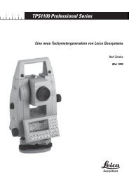
<strong>TPS1100</strong> <strong>Professional</strong> <strong>Series</strong><br />
A New Generation of Total Stations from Leica Geosystems<br />
Karl Zeiske<br />
May 1999<br />
L<br />
MADE TO MEASURE<br />
1
Summary<br />
This report describes the main components of the<br />
new generation of total stations, a further development<br />
of the successful TPS System 1000 series. The<br />
angle-measuring system, the measurement of distance<br />
without the use of a reflector, the automatic<br />
target recognition and the flexible coding are all dealt<br />
with in detail.<br />
The application of new technologies and the implementation<br />
of the wishes of customers across the<br />
globe have led to appreciable improvements in the<br />
operating concept and in the functionality. The resulting<br />
expansion of the range of applications, and the<br />
simplification of procedures, have made it possible to<br />
improve productivity substantially.<br />
1. Overview<br />
The new generation of total stations has been developed<br />
from the successful TPS System 1000 series,<br />
from which it has adopted the most successful features.<br />
Much has been improved, and the functionality<br />
expanded, on the basis of input from customers all<br />
over the world. As a result of new technologies, the<br />
instruments have become smaller and lighter and the<br />
measuring procedures have been accelerated.<br />
The existing operating concept, involving the large<br />
eight-line display and the clear, systematically-arranged<br />
keyboard, has been retained. Years of experience<br />
with the TPS1000 instruments have enabled the<br />
user guidance and the operation to be clarified and<br />
simplified yet further.<br />
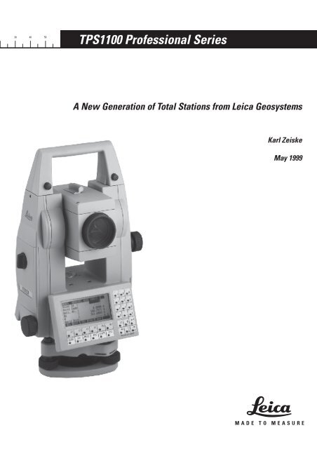
Fig 1: Motorized total station with automatic target<br />
recognition and EGL electronic guide light<br />
2<br />
The improved automatic target recognition system<br />
allows higher-speed tracking than was possible with<br />
the TPS1000 instruments.<br />
For the first time, an electronic total station includes<br />
not only the established infrared distancer which<br />
measures to prisms and reflector tapes, but also a<br />
distancer for reflectorless measurement and in which<br />
the emitter projects a visible laser beam.<br />
Other new features are the use of camcorder batteries<br />
as the power supply, the endless fine drives even with<br />
the instrument models which are not motorized, and<br />
the laser plummet permanently in the vertical axis as<br />
a standard feature. The spot brightness of this laser<br />
plummet is adjustable, so that the instrument can be<br />
set up over the ground point quickly and conveniently,<br />
irrespective of the ambient conditions.<br />
Many versions of the instrument are available. The<br />
user can choose the most appropriate of them:<br />
TC….. Classical total station<br />
TCM….. Motorized total station<br />
TCR….. Total station with reflectorless<br />
distancer<br />
TCRM….. Motorized total station with<br />
reflectorless distancer<br />
TCA….. Motorized total station with automatic<br />
target recognition<br />
Each of these versions is produced at four different<br />
levels of accuracy (angle-measuring accuracy in<br />
accordance with DIN 18723 and ISO 12857).<br />
Type 1101 1.5” , 0.5 mgon<br />
Type 1102 2” , 0.6 mgon<br />
Type 1103 3” , 1.0 mgon<br />
Type 1105 5” , 1.5 mgon
2. Measuring angles<br />
In the static, absolute circle-scanning system used,<br />
the coded graduations of a glass circle are read<br />
optoelectronically (fig. 2).<br />
Fig. 2: The circle-scanning principle<br />
Unlike most absolute angle-measuring systems on<br />
the market, where the position has to be decoded<br />
from several parallel tracks, the circle carries only one<br />
graduation track, the code of which continually alters<br />
and contains all of the positional information. This<br />
code is read by means of a linear CCD array and an 8bit<br />
A/D converter, and supplies the approximate<br />
position with an accuracy of around 0.3 gon.<br />
Determining the positions of the centres of the individual<br />
code lines on the array, and then using an<br />
appropriate algorithm to find the mean, produces the<br />
fine measurement. A minimum of ten code lines must<br />
be captured in order to determine the position. In<br />
general, however, a single measurement involves<br />
around 60 code lines, improving the interpolation<br />
accuracy, the redundancy and the reproducibility. The<br />
principle of this angle-measuring system is applied to<br />
all Leica theodolites and total stations.<br />
The value measured for the horizontal direction is<br />
corrected before being displayed or recorded. The<br />
correction is calculated from the following parameters,<br />
as a function of the vertical angle measured:<br />
- the latest collimation error and tilting-axis error to<br />
be determined and stored in the instrument<br />
- the momentary component of the vertical-axis tilt,<br />
transverse to the line of sight.<br />
The vertical angle is corrected by the amount of the<br />
stored index error and by the component of the<br />
vertical-axis tilt in the direction of the line of sight. A<br />
tilt sensor monitors both components of the verticalaxis<br />
tilt. Fig. 3 shows the principle of a tilt sensor, in<br />
which a liquid mirror forms the reference horizon.<br />
<br />
1 - Reticle on prism<br />
2 - Oil surface<br />
3 - Deviating prism<br />
4 - Imaging lens<br />
Fig. 3: Tilt sensor<br />
<br />
<br />
<br />
<br />
<br />
5 - Image of the reticle<br />
6 - CCD linear array<br />
7 - Illuminator (LED)<br />
The reticle (1) located on the prism is illuminated (7),<br />
and is imaged (5) on the linear CCD array (6) by way<br />
of the imaging lens (4) after double reflection at the<br />
liquid surface (2). The triangular line pattern of the<br />
reticle makes it possible to capture both tilt components<br />
by means of just one unidimensional receiver.<br />
Longitudinal tilt alters the spacing between the differently-oriented<br />
lines; transverse tilt shifts the centre of<br />
the entire line pattern along the CCD array.<br />
This arrangement enables the tilt sensor to be made<br />
so small that ideally it could be placed centrally over<br />
the vertical axis. The liquid mirror would then be<br />
displaced from its horizontal position only very<br />
slightly, even during rapid rotation of the alidade.<br />
Also, the tilt measurement can no longer be affected<br />
by other factors such as the temperature-related<br />
deformation of the theodolite standard.<br />
<br />
3
3. Measuring Distance<br />
Two coaxially-measuring distancers are incorporated<br />
into the TCR instruments (fig. 4). Both distancers<br />
operate on the well-known phase measurement<br />
principle.<br />
The infrared laser beam for measuring distances to<br />
prisms and reflector tapes has a wavelength of<br />
780nm, a range of 3000 metres with a single prism,<br />
and an accuracy of 2mm + 2ppm. The visible red laser<br />
beam has a wavelength of 670nm and measures<br />
distances of up to 80 metres with an accuracy of 3mm<br />
+ 2ppm without using a reflector.<br />
Fig. 4: Optical design of a total station measuring without reflector<br />
The unambiguity of the distance measurement up to<br />
12km is assured by a special frequency system. Its<br />
base is a frequency of 100MHz, corresponding to a<br />
measuring scale of 1.5m.<br />
The “Long Range“ measuring mode can be engaged<br />
for long distances. With it, the red laser beam can<br />
also be used to measure to prisms at a distance of<br />
between 1000 metres and 5000 metres.<br />
A keystroke will switch between the two distancers<br />
immediately and at any time. The correct zero-point<br />
correction (additive constant) is set automatically.<br />
This combination of two distancers in a single total<br />
station, achieved now for the first time, offers great<br />
advantages where the points to be measured are<br />
4<br />
Reflector, target<br />
Laser for<br />
reflectorless<br />
measurement<br />
Laser for<br />
reflectorsupported<br />
measurement<br />
accessible only with difficulty or not at all, for example<br />
on frontages, during control measurements on<br />
steel constructions, and in determining lengths of<br />
conduits. The visible red laser beam can also be<br />
switched on permanently for marking target points,<br />
e.g. for profile surveys in tunnels or for indoor surveys.<br />
At a distance of 50 metres the laser dot has a<br />
size of approximately 1cm x 2cm.<br />
Receiver<br />
diode<br />
Motor<br />
Graded filter / internal light path<br />
Telescope of total station
4. Automatic target recognition<br />
4.1 The Principle<br />
Automatic target recognition (ATR) is incorporated<br />
into the telescope in the same manner as is the EDM.<br />
An infrared laser beam is projected coaxially into the<br />
telescope axis by means of optical components and<br />
emerges from the main objective. A beam splitter<br />
separates the reflected beam of the ATR from the<br />
EDM beam and from the visible light, and guides it to<br />
the receiver (the video sensor).<br />
Special hardware adds the intensities of the elements<br />
of the video sensor in rows and in columns, resulting<br />
in two “projections”. The centres of these are determined<br />
by a processor and are then transformed into a<br />
horizontal and a vertical angle of correction with<br />
regard to the visual line of sight. These angle corrections<br />
are used to correct the values relating to the<br />
visual line of sight, as measured by the circle-scanning<br />
system.<br />
4.2 Fine pointing<br />
Three sequentially-running processes characterize the<br />
fine pointing: the search process, the targeting process<br />
and the measuring process.<br />
After the coarse manual pointing of a prism, the fine<br />
pointing with the help of ATR is completely automatic.<br />
ATR first checks whether the coarsely-targeted<br />
prism is located within the field of view of the telescope.<br />
If it cannot detect the prism, it commences a<br />
search procedure involving a continuous spiral movement<br />
of the telescope. The speed of this scan is<br />
selected so that there are no gaps between the individual<br />
images in the area scanned. The telescope<br />
stops moving as soon as the prism has been detected.<br />
When using the ATR measuring technique, it is not<br />
necessary to target the prism centrally in order to<br />
determine the horizontal direction and the vertical<br />
angle. Nevertheless Hz and V angle corrections are<br />
determined during the subsequent targeting process<br />
when the motor moves the telescope so that it points<br />
to the centre of the prism within the predetermined<br />
tolerance limits.<br />
There are two reasons for this: firstly, so that the user<br />
can confirm the correct automatic targeting by visual<br />
observation and secondly, so that a distance can be<br />
measured at the same time. ATR requires one prism<br />
for target identification and so, to simplify operation,<br />
the ATR angle measurement has been coupled to the<br />
triggering of a distance measurement.<br />
During the measuring procedure, angle corrections<br />
are redetermined, the horizontal and vertical angles<br />
are corrected appropriately, and the distance is<br />
measured or the target-point coordinates are calcu-<br />
lated. Fig. 5 shows the sequence of an ATR measurement<br />
procedure.<br />
The measuring accuracy of ATR in its standard setting<br />
corresponds to the angle-measuring accuracy of the<br />
corresponding instrument model. If a distancemeasuring<br />
mode different from the standard one is<br />
selected, the accuracy of the ATR measurement<br />
adapts to the accuracy class of this measuring mode.<br />
In, for example, the distance-measuring mode “Fast“,<br />
this shortens the measuring time and enables the<br />
measurement to be carried out on unstable, handheld<br />
reflectors at close range.<br />
When ATR is used for measuring, there is no need to<br />
focus the telescope or to fine-point the target, and so<br />
the speed of measurement is increased enormously<br />
and the precision, which is independent of the observer,<br />
remains constant.<br />
4.3 Tracking the target<br />
Tracking is essentially an automatic control system,<br />
or feedback loop (fig. 6). The theodolite drive, the<br />
control range, consists of two axes each with a servomotor,<br />
a transmission and a circle-scanning system.<br />
The ATR is a measuring system, which supplies not<br />
only the actual values, but also the deviation between<br />
actual and required values and the horizontal and<br />
vertical corrections from the electronic or optical line<br />
of sight. The automatic control system is intended to<br />
minimize the deviations, irrespective of the speed and<br />
acceleration of the target. The deviations are read off<br />
at the video rate; from them, the circuit determines<br />
the currents needed by the motor in order to attain<br />
the set goal.<br />
This procedure runs continuously throughout the<br />
tracking phase. If contact with the target is lost, e.g. if<br />
the reflector carrier passes behind an obstacle, the<br />
tracking process is interrupted. The values that then<br />
become effective instead of the deviation values are<br />
based on a movement model, which assumes the<br />
horizontal and vertical speeds of the reflector carrier<br />
to be constant. These speeds are derived from the<br />
filtered movement before loss of contact. Filtering<br />
serves to eliminate superimposed frequencies such<br />
as the vertical component of walking. Because the<br />
model is just an approximation of the movement, it is<br />
applied only for a period of a few seconds.<br />
If measurements are triggered parallel to the tracking<br />
process, the course of the moving target can be<br />
determined. The time synchronization of the individual<br />
sensors of the total station has a considerable<br />
influence in this application. The measuring systems<br />
are integrated for different periods, and so the true<br />
time at which they are determined has to be established<br />
and then interpolated or extrapolated to a<br />
common point in time.<br />
5
6<br />
Á<br />
<br />
<br />
&%. 1SPDFTTPS<br />
Fig. 5: The sequence of an ATR measurement<br />
Á<br />
Á<br />
Fig. 6: Feedback loop of target tracking<br />
<br />
Á<br />
<br />
ÁÁ<br />
ÁÁ<br />
<br />
<br />
<br />
<br />
Á<br />
<br />
Á<br />
<br />
<br />
Á<br />
Á<br />
Á<br />
Á<br />
<br />
Á<br />
Á<br />
Á<br />
<br />
Á<br />
Á<br />
Á<br />
<br />
5IFPEPMJUF 1SPDFTTPS "53 1SPDFTTPS<br />
"53 1SPDFTTPS 5IFPEPMJUF 1SPDFTTPS<br />
<br />
<br />
Á Á<br />
Á<br />
Á
5. Remote control<br />
The remote-control system RCS1100 is an additional<br />
option for all Leica total stations. It is particularly<br />
efficient in conjunction with instruments that have<br />
automatic target recognition. The controller, battery,<br />
radio modem and antenna of the RCS1100 form a<br />
compact unit, which fits easily to a reflector pole (fig.<br />
7). The display and keyboard of the controller are<br />
identical to those of the total station, and so all instrument<br />
functions, including the applications programs,<br />
can be called up from the target area.<br />
Fig. 7: RCS1100 remote control system<br />
The remote control system makes it easier to capture<br />
important additional information at the target area in<br />
particular, and offers great advantages during stakeout.<br />
After a measurement, the path difference from<br />
the reflector to the point to be set out is calculated<br />
and is displayed on the controller. This facilitates and<br />
accelerates the stakeout procedure, and also enables<br />
the accuracy of the stakeout to be inspected directly<br />
from the target area.<br />
The EGL electronic guide light provides additional<br />
help during stakeout; it is a flashing light source,<br />
which can be built into any telescope housing (fig. 1),<br />
and enables the reflector carrier to be aligned with the<br />
line of sight of the instrument.<br />
6. Software<br />
The entire software for the <strong>TPS1100</strong> instruments can<br />
be roughly divided into three groups:<br />
- The systems software for controlling all basic<br />
functions of the total station<br />
- The comprehensive library of applications programs<br />
- The LEICA SurveyOffice, PC programs package for<br />
communication between instrument and computer.<br />
6.1. System software<br />
The system software controls all measurement<br />
functions, the display and the recording. For each<br />
dialogue in the display (e.g. measuring, data management,<br />
calibration etc.), the function keys are occupied<br />
by the appropriate relevant function. This ensures<br />
ideal user guidance along with quick and easy operation.<br />
All measurement sequences, and the functions which<br />
can be called from the various dialogues, are logically<br />
arranged. They can also be configured and so<br />
matched to individual user requirements.<br />
In the measuring dialogue, three different display<br />
templates can be defined; a keystroke switches<br />
between them so that the user has an overview of all<br />
important data.<br />
Five different recording templates can be defined<br />
quite independently of the display templates. 12<br />
items of data in any sequence can be recorded in any<br />
one measuring block. There is a choice between data<br />
formats containing either 8 or 16 characters per data<br />
word.<br />
All data can be stored on PCMCIA memory cards in<br />
various files, or can be exported via the RS232 interface<br />
to an external computer. Up to 60 files can be<br />
managed; they can be given any name. A distinction<br />
is made between measurement files for storing<br />
measurements, files with fixed-point coordinates,<br />
and code lists.<br />
Code lists with additional information for the postprocessing<br />
of measurement data can be imported<br />
directly through the keyboard into the instrument, but<br />
it is preferable to compile code lists on a PC with the<br />
program “Codelist Manager” from the Leica Survey<br />
Office and then to import this into the instrument.<br />
For standard coding, the appropriate code is selected<br />
from the list and then stored in a separate code block.<br />
A code block can contain a code and up to eight<br />
additional items of information. If no code list has<br />
been stored in the instrument, code blocks can also<br />
be entered manually via the keyboard and stored.<br />
7
Rapid coding (“Quick-Code”) is a special function<br />
with which a keystroke triggers a measurement, after<br />
which the measurement block and the corresponding<br />
code block are recorded automatically. To do this, a<br />
single-digit or two-digit number must be allocated to<br />
each code as a quick-code abbreviation when the<br />
code list is compiled with the “Codelist Manager” PC<br />
program. After the point has been targeted, it is<br />
enough to enter this number using the numeric<br />
keyboard. This action triggers a distance measurement,<br />
and stores the complete measurement block in<br />
accordance with the recording template selected and<br />
with the associated code block from the code list. The<br />
user can decide whether the measurement block or<br />
the code block should be the first to be stored.<br />
Point-related codes, and also up to eight attributes,<br />
can also be recorded along with each measurementdata<br />
block. The input is directly through the measurement<br />
dialogue. The precondition for this is that the<br />
point code and the attribute are defined both in the<br />
display and in the recording template.<br />
6.2. Applications programs<br />
To deal with the most important tasks in surveying,<br />
the following applications programs are incorporated<br />
into all instruments:<br />
Horizontal-circle orientation and height transfer<br />
Resection<br />
Free-station survey<br />
Setting out (stakeout)<br />
Computation of tie distance<br />
Remote height<br />
The user can load the following optional programs at<br />
any time:<br />
Reference line<br />
Area computation<br />
Hidden points<br />
Sets of angles<br />
Traverse<br />
Local resection<br />
Road stakeout<br />
File Editor<br />
COGO functions<br />
Auto Record (acceleration of mass point surveys)<br />
Face Scan for TCRM instruments<br />
DTM stakeout<br />
Leica offers GEOBASIC, a modern development<br />
environment within which users can develop their<br />
own individual applications programs.<br />
Printed in Switzerland. Copyright Leica Geosystems AG, Heerbrugg, Switzerland, 1999<br />
712705en - V.99 - RVA<br />
8<br />
6.3. LEICA SurveyOffice<br />
The LEICA SurveyOffice is a PC software package<br />
with the following functions:<br />
- Exchange of data between instrument and PC<br />
- Creation of code lists universally usable in the<br />
TPS300 instruments, the <strong>TPS1100</strong> instruments and<br />
the new GPS500 system<br />
- Loading and deleting systems software and applications<br />
programs and related display texts in various<br />
languages.<br />
Leica Geosystems AG<br />
Geodesy<br />
Heinrich-Wild-Strasse<br />
CH-9435 Heerbrugg<br />
Switzerland<br />
Phone +41 71 727 3131<br />
Fax +41 71 727 4702<br />
www.leica-geosystems.com