GS-12-239 - FCI
GS-12-239 - FCI
GS-12-239 - FCI

You also want an ePaper? Increase the reach of your titles
YUMPU automatically turns print PDFs into web optimized ePapers that Google loves.
NUMBER<br />
<strong>GS</strong>-<strong>12</strong>-<strong>239</strong><br />
TYPE<br />
PRODUCT SPECIFICATION<br />
TITLE PAGE REVISION<br />
Copyright <strong>FCI</strong><br />
Form E-3334<br />
Rev F<br />
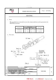
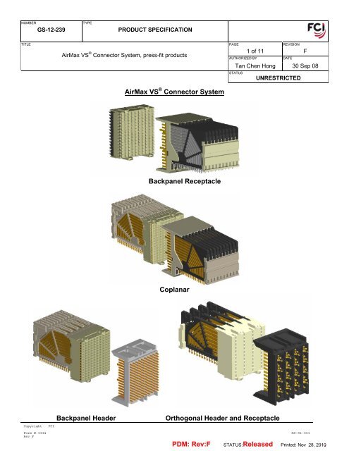
AirMax VS ® Connector System, press-fit products<br />
AirMax VS ® Connector System<br />
Backpanel Receptacle<br />
Coplanar<br />
1 of 11 F<br />
AUTHORIZED BY DATE<br />
Tan Chen Hong 30 Sep 08<br />
STATUS<br />
UNRESTRICTED<br />
Backpanel Header Orthogonal Header and Receptacle<br />
<strong>GS</strong>-01-001<br />
PDM: Rev:F STATUS: Released Printed: Nov 28, 2010.
NUMBER<br />
<strong>GS</strong>-<strong>12</strong>-<strong>239</strong><br />
TYPE<br />
PRODUCT SPECIFICATION<br />
TITLE PAGE REVISION<br />
TABLE OF CONTENTS:<br />
Copyright <strong>FCI</strong><br />
Form E-3334<br />
Rev F<br />
AirMax VS ® Connector System, press-fit products<br />
2 of 11 F<br />
AUTHORIZED BY DATE<br />
Tan Chen Hong 30 Sep 08<br />
STATUS<br />
UNRESTRICTED<br />
1.0 OBJECTIVE ........................................................................................................................ 3<br />
2.0 SCOPE................................................................................................................................ 3<br />
3.0 APPLICABLE DOCUMENTS .............................................................................................. 3<br />
3.1 <strong>FCI</strong> Specifications ............................................................................................................. 3<br />
3.2 Other Standards and Specifications ................................................................................. 3<br />
3.3 <strong>FCI</strong> Product Qualification Test reports.............................................................................. 3<br />
4.0 REQUIREMENTS ................................................................................................................. 3<br />
4.1 Materials............................................................................................................................. 3<br />
4.2 Visual Examination of Product ........................................................................................... 3<br />
5.0 ELECTRICAL CHARACTERISTICS..................................................................................... 4<br />
5.1 Low Level Contact Resistance........................................................................................... 4<br />
5.2 Insulation Resistance......................................................................................................... 4<br />
5.3 Dielectric Withstanding Voltage ......................................................................................... 4<br />
5.4 Current Rating.................................................................................................................... 4<br />
6.0 MECHANICAL CHARACTERISTICS.................................................................................... 5<br />
6.1 Mating / Un-mating Force................................................................................................... 5<br />
6.2 Compliant pin insertion force ............................................................................................. 5<br />
6.3 Compliant pin retention force ............................................................................................. 5<br />
6.4 PCB Hole Deformation Radius .......................................................................................... 5<br />
6.5 PCB Hole Wall Damage.....................................................................................................5<br />
7.0 ENVIRONMENTAL CONDITIONS........................................................................................ 6<br />
7.1 Thermal Shock: .................................................................................................................. 6<br />
7.2 Cyclical Humidity and Temperature: .................................................................................. 6<br />
7.3 Temperature Life:............................................................................................................... 6<br />
7.4 Industrial Mixed Flowing Gas (Class IIA, 4-gas):............................................................... 6<br />
7.5 Vibration ............................................................................................................................. 7<br />
7.6 Mechanical Shock .............................................................................................................. 7<br />
7.7 Durability ............................................................................................................................ 7<br />
7.8 Dust Contamination............................................................................................................ 7<br />
7.9 Disturb ................................................................................................................................ 7<br />
8.0 QUALITY ASSURANCE PROVISIONS................................................................................ 8<br />
8.1 Equipment Calibration........................................................................................................ 8<br />
8.2 Inspection Conditions......................................................................................................... 8<br />
8.3 Sample Quantity and Description ...................................................................................... 8<br />
8.4 Acceptance ........................................................................................................................ 8<br />
8.5 Qualification Testing........................................................................................................... 8<br />
8.6 Re-Qualification Testing..................................................................................................... 8<br />
Table 1: Qualification Test Matrix............................................................................................... 9<br />
Table 2: Qualification Sample Requirements........................................................................... 10<br />
REVISION RECORD .......................................................................................................................... 11<br />
<strong>GS</strong>-01-001<br />
PDM: Rev:F STATUS: Released Printed: Nov 28, 2010.
NUMBER<br />
<strong>GS</strong>-<strong>12</strong>-<strong>239</strong><br />
TYPE<br />
PRODUCT SPECIFICATION<br />
TITLE PAGE REVISION<br />
1.0 OBJECTIVE<br />
Copyright <strong>FCI</strong><br />
Form E-3334<br />
Rev F<br />
AirMax VS ® Connector System, press-fit products<br />
3 of 11 F<br />
AUTHORIZED BY DATE<br />
Tan Chen Hong 30 Sep 08<br />
STATUS<br />
UNRESTRICTED<br />
This specification defines the performance, test, and quality and reliability requirements of the press-fit AirMax<br />
VS ® Connector System. This specification applies to all press-fit backpanel, coplanar and orthogonal receptacles<br />
and headers, including 5 pair, 4 pair, and 3 pair products on both 2mm and 3mm column pitch and 4 pair<br />
orthogonal receptacles and headers on 4.2mm column pitch. The test sequences defined in this specification<br />
meet the intent of Telcordia GR-<strong>12</strong>17-CORE requirements.<br />
2.0 SCOPE<br />
This specification is applicable to the termination characteristics of the press-fit AirMax VS ® Connector System<br />
which provides a high speed board-to-board interconnect for differential pairs and single-ended lines.<br />
3.0 APPLICABLE DOCUMENTS<br />
3.1 <strong>FCI</strong> Specifications<br />
- Applicable <strong>FCI</strong> product customer drawings<br />
- <strong>FCI</strong> Application Specification <strong>GS</strong>-20-035 (AirMax VS ® Connector System, press-fit products)<br />
3.2 Other Standards and Specifications<br />
- UL94V-O: Test for Flammability of Plastic Materials in Devices and Appliances<br />
- EIA 364: Electrical Connector/Socket Test Procedures Including Environmental Classifications<br />
- GR-<strong>12</strong>17-CORE: Telcordia Specification “Generic Requirements for Separable Electrical Connectors”<br />
3.3 <strong>FCI</strong> Product Qualification Test reports<br />
- EL 2004-03-008D: Press-fit AirMax VS ® Backpanel Receptacle products<br />
- EL 2006-04-004D: Press-fit AirMax VS ® Backpanel Receptacle products, Performance-based Plating,<br />
GXT TM & Hard Gold contact cross-mating<br />
- EL 2006-07-022A: Press-fit AirMax VS ® Backpanel Header products<br />
- EL 2008-08-017 : Press-fit AirMax VS ® Orthogonal Header and Receptacle products<br />
4.0 REQUIREMENTS<br />
4.1 Materials<br />
The material for each component shall be as specified herein or equivalent.<br />
- Contacts: copper alloy<br />
- Plating:<br />
Contact Areas: Performance-based plating, qualified to meet the requirements of this specification,<br />
including the Telcordia GR-<strong>12</strong>17-CORE (November 1995) Central Office test<br />
sequence.<br />
Press-fit Tails: Tin or tin-lead over nickel<br />
- Housings: high temperature thermoplastic; UL 94V-0 compliant<br />
4.2 Visual Examination of Product<br />
Visual examinations shall be performed using 10x magnification. Parts should be free from blistering,<br />
cracks, discoloration, etc.<br />
<strong>GS</strong>-01-001<br />
PDM: Rev:F STATUS: Released Printed: Nov 28, 2010.
NUMBER<br />
<strong>GS</strong>-<strong>12</strong>-<strong>239</strong><br />
TYPE<br />
PRODUCT SPECIFICATION<br />
TITLE PAGE REVISION<br />
AirMax VS ® Connector System, press-fit products<br />
5.0 ELECTRICAL CHARACTERISTICS<br />
Copyright <strong>FCI</strong><br />
Form E-3334<br />
Rev F<br />
4 of 11 F<br />
AUTHORIZED BY DATE<br />
Tan Chen Hong 30 Sep 08<br />
STATUS<br />
UNRESTRICTED<br />
5.1 Low Level Contact Resistance<br />
Measurements shall be performed using a four-wire method per EIA 364-23B. The maximum initial signal<br />
contact resistance is 35 mΩ for backpanel and orthogonal (one mated interface) applications and 50 mΩ<br />
for coplanar applications. The increase in resistance for any position shall not exceed 10 mΩ. The<br />
following details apply:<br />
a. Test voltage: 20 mV maximum open circuit<br />
b. Test current: 100 mA maximum<br />
c. Number of readings: 500 minimum<br />
5.2 Insulation Resistance<br />
The insulation resistance of mated connectors shall not be less than 1000 MΩ after environmental<br />
exposure when measured in accordance with EIA 364-21C. The following details shall apply:<br />
a. Test voltage: 500 VDC<br />
b. Electrification time: 60 seconds<br />
c. Points of measurement: between closest adjacent contacts<br />
d. Number of readings: 30 (10 readings per loose-piece connector set)<br />
5.3 Dielectric Withstanding Voltage<br />
There shall be no evidence of arc-over, insulation breakdown, or excessive leakage current (> 0.5 mA)<br />
when the mated connectors are tested in accordance with EIA 364-20C. The following details shall apply:<br />
a. Test voltage: 500 VAC, 60Hz<br />
b. Test duration: 60 seconds<br />
c. Voltage application rate: 500 V per second<br />
d. Points of Measurement: between closest adjacent contacts<br />
e. Number of readings: 30 (10 readings per loose-piece connector set)<br />
5.4 Current Rating<br />
Perform in accordance with EIA 364-70A. Measure temperature vs. applied current for all contacts<br />
powered. The following details shall apply:<br />
a. Ambient conditions: still air at 25 o C<br />
b. Thermocouple location: mechanically attached to the base of the header mating contacts<br />
c. Copper trace weight: 1 oz<br />
d. Quantity and location of thermocouples: 10 (5 on an interior column at positions A, C, E, G, and I;<br />
5 on an outside column at positions A, C, E, F, G, and I)<br />
The temperature rise above ambient shall not exceed 30 degrees C with all contacts powered at 0.5A.<br />
<strong>GS</strong>-01-001<br />
PDM: Rev:F STATUS: Released Printed: Nov 28, 2010.
NUMBER<br />
<strong>GS</strong>-<strong>12</strong>-<strong>239</strong><br />
TYPE<br />
PRODUCT SPECIFICATION<br />
TITLE PAGE REVISION<br />
AirMax VS ® Connector System, press-fit products<br />
6.0 MECHANICAL CHARACTERISTICS<br />
Copyright <strong>FCI</strong><br />
Form E-3334<br />
Rev F<br />
5 of 11 F<br />
AUTHORIZED BY DATE<br />
Tan Chen Hong 30 Sep 08<br />
STATUS<br />
UNRESTRICTED<br />
6.1 Mating / Un-mating Force<br />
Perform in accordance with EIA 364-13B. The force to mate a receptacle connector and compatible<br />
header shall not exceed 0.45 N per contact (0.60 N per orthogonal contact). The un-mating force shall<br />
not be less than 0.15 N per contact. The following details shall apply:<br />
a. Cross head speed: 1 inch per minute<br />
b. Lubrication: None<br />
c. Utilize free-floating fixtures<br />
d. Number of mate/un-mate cycles: 3<br />
e. Number of mated connector pairs to be tested: 10<br />
6.2 Compliant pin insertion force<br />
Perform in accordance with EIA 364-05B. Fully populated connectors shall be applied to test boards with<br />
minimum, maximum, and nominal size plated through holes (as defined in Table 2) using an electric<br />
application press and <strong>FCI</strong> recommended application tooling. The following details shall apply:<br />
a. Force to insert one straight or right angle header pin: 40 N maximum<br />
b. Force to insert one right angle receptacle pin: 40 N maximum<br />
c. Force to insert one straight receptacle or orthogonal header pin: 25 N maximum<br />
d. Number of readings: 1 per connector assembly tested<br />
e. Number of connectors to be tested: 13 sets (3 sets in minimum holes; 5 sets in nominal holes; 5 sets<br />
in maximum holes)<br />
6.3 Compliant pin retention force<br />
Perform in accordance with EIA 364-05B. Fully populated connectors shall be removed from test boards<br />
with minimum, maximum, or nominal size plated through holes (as defined in Table 2) using an electric<br />
application press and <strong>FCI</strong> recommended removal tooling. The following details shall apply:<br />
a. Force to remove one straight or right angle header pin: 7 N minimum<br />
b. Force to remove one right angle receptacle pin: 7 N minimum<br />
c. Force to remove one straight receptacle or orthogonal header pin: 3 N minimum<br />
d. Number of connectors to be tested: 13 sets (3 sets in minimum holes; 5 sets in nominal holes; 5 sets<br />
in maximum holes)<br />
6.4 PCB Hole Deformation Radius<br />
Perform in accordance with Telcordia GR-<strong>12</strong>17-CORE, November 1995, Section 5.1.7. Use test boards<br />
with minimum diameter plated through holes. Make cross-sections 0.25mm (0.010 inch) from the top<br />
board surface and near the center of the press-fit section. Photograph and measure the minimum copper<br />
thickness remaining between the compliant pin and the printed wiring board laminate and the hole<br />
deformation radius. The minimum average copper thickness remaining between the compliant pin and<br />
the printed wiring board laminate shall not be less than 7.5 µm (0.0003”). The maximum average hole<br />
deformation radius shall be no greater than 37.5 µm (0.0015”). The maximum hole deformation radius<br />
reading must not exceed 50 µm (0.0020”). Test 15 holes.<br />
6.5 PCB Hole Wall Damage<br />
Perform in accordance with Telcordia GR-<strong>12</strong>17-CORE, November 1995, Section 5.1.7. Use test boards<br />
with minimum diameter plated through holes. Cross-section perpendicular to the board surface and<br />
through the compliant section wear track. There shall be no copper cracks, separations between<br />
conductive interfaces, or laminate-to-copper separations. Test 15 pins.<br />
<strong>GS</strong>-01-001<br />
PDM: Rev:F STATUS: Released Printed: Nov 28, 2010.
NUMBER<br />
<strong>GS</strong>-<strong>12</strong>-<strong>239</strong><br />
TYPE<br />
PRODUCT SPECIFICATION<br />
TITLE PAGE REVISION<br />
Copyright <strong>FCI</strong><br />
Form E-3334<br />
Rev F<br />
AirMax VS ® Connector System, press-fit products<br />
6 of 11 F<br />
AUTHORIZED BY DATE<br />
Tan Chen Hong 30 Sep 08<br />
STATUS<br />
UNRESTRICTED<br />
7.0 ENVIRONMENTAL CONDITIONS<br />
After exposure to the following environmental conditions in accordance with “Table 1 – Qualification Test Matrix”,<br />
the product shall show no physical damage and shall meet the electrical and mechanical requirements in sections<br />
6 and 7. Unless specified otherwise the products shall be mated during exposure.<br />
7.1 Thermal Shock:<br />
Perform in accordance with EIA 364-32C. The following details shall apply:<br />
a. Number of cycles: 5<br />
b. Temperature range: -55 to + 85 o C<br />
c. Time at each temperature: 30 minutes minimum<br />
d. Transfer time: 30 seconds maximum<br />
7.2 Cyclical Humidity and Temperature:<br />
Mated samples are to be exposed to cyclical humidity and temperature in accordance with EIA 364-31B.<br />
Samples are to be subjected to 50 cycles of 10-hour duration for a total of 500 hours.<br />
A cycle consists of the following steps.<br />
a. 2 hour ramp from 25°C at 80%-98% RH to 65°C at 90%-98% RH<br />
b. 4 hour dwell at 65°C at 90%-98% RH<br />
c. 2 hour ramp down to 25°C at 80%-98% RH<br />
d. 2 hour dwell at 25°C at 80%-98% RH<br />
7.3 Temperature Life:<br />
Perform in accordance with EIA 364-17B. Headers and receptacles shall remain mated without any<br />
electrical load. The following details shall apply:<br />
a. Temperature: 85°C<br />
b. Duration: 500 hours<br />
7.4 Industrial Mixed Flowing Gas (Class IIA, 4-gas):<br />
Expose samples to gas mixture per Telcordia GR-<strong>12</strong>17-CORE, November 1995, Section 9.1.3 as follows:<br />
a. Temperature: 30°C<br />
b. Relative humidity: 70%<br />
c. Mandatory readings after the 10 th and 20 th days<br />
d. Gas compositions, per Central Office requirements:<br />
Gas Type Gas Concentration<br />
NO2<br />
200 ppb<br />
Cl2<br />
10 ppb<br />
H2S 10 ppb<br />
SO2<br />
100 ppb<br />
Case 1: Backpanel and Orthogonal Applications<br />
Un-mated backpanel connectors are to be exposed to gas mixture for 10 days, then mated and exposed<br />
for an additional 10 days.<br />
Case 2: Coplanar Applications<br />
Each connector gender is to be exposed to gas mixture in the unmated condition for 10 days, then mated<br />
to an unexposed connector for a 10 day additional gas exposure and the remainder of the test.<br />
<strong>GS</strong>-01-001<br />
PDM: Rev:F STATUS: Released Printed: Nov 28, 2010.
NUMBER<br />
<strong>GS</strong>-<strong>12</strong>-<strong>239</strong><br />
TYPE<br />
PRODUCT SPECIFICATION<br />
TITLE PAGE REVISION<br />
Copyright <strong>FCI</strong><br />
Form E-3334<br />
Rev F<br />
AirMax VS ® Connector System, press-fit products<br />
7 of 11 F<br />
AUTHORIZED BY DATE<br />
Tan Chen Hong 30 Sep 08<br />
STATUS<br />
UNRESTRICTED<br />
7.5 Vibration<br />
Perform in accordance with Telcordia GR-<strong>12</strong>17-CORE, November 1995, Sections 6.3.5 and 9.1.2.1. The<br />
following details shall apply:<br />
a. Vibration amplitude: 1.5 mm (0.06 inch) double amplitude or 10G acceleration<br />
b. Frequency range: 10 to 500 to 10 Hz<br />
c. Sweep time: 15 minutes per cycle<br />
d. Duration: 8 hours along each of three orthogonal axes (24 hours total)<br />
e. Mounting: rigidly mounted assemblies<br />
f. No discontinuities greater than 1 micro-second<br />
7.6 Mechanical Shock<br />
Perform in accordance with Telcordia GR-<strong>12</strong>17-CORE, November 1995, Sections 6.3.5 and 9.1.2.1. The<br />
following details shall apply:<br />
a. Amplitude: half sine 30G<br />
b. Duration: 11 milliseconds<br />
c. Number of shocks: 3 shocks along each of three orthogonal axis (18 total)<br />
d. Mounting: rigidly mounted assemblies<br />
e. Take resistance measurements after shock in each axis<br />
f. No discontinuities greater than 1 micro-second<br />
7.7 Durability<br />
Perform in accordance with EIA 364-09C. Use standard laboratory procedure as applicable to the<br />
specific product. The following details shall apply:<br />
a. Number of cycles: See Table 1 (200 total mating cycles)<br />
b. Cycling rate: <strong>12</strong>.5 cm (5 inches) per minute<br />
7.8 Dust Contamination<br />
Perform in accordance with Telcordia GR-<strong>12</strong>17-CORE, November 1995, Section 9.1.1.1 & Table 9-1.<br />
Samples shall be subjected to a one-hour dust exposure using a benign dust composition as specified in<br />
Table 9-1 of Telcordia GR-<strong>12</strong>17-CORE, November 1995, and in accordance with the following:<br />
Case 1: Backpanel and Orthogonal Applications<br />
Un-mated backpanel connectors alone shall be subjected to dust exposure.<br />
Case 2: Coplanar Applications<br />
Each connector gender is to be subjected to dust exposure in the unmated condition, then mated to an<br />
unexposed connector for the remainder of the test sequence. Alternatively, in order to reduce the need<br />
for additional samples, the mating halves may be subjected to dust exposure and re-mated to each other<br />
for the remainder of the test sequence.<br />
7.9 Disturb<br />
Perform in accordance with Telcordia GR-<strong>12</strong>17-CORE, November 1995, Section 9.1.3.3 paragraph 7.<br />
The mated connectors shall be subjected to an interface disturbance that consists of slightly unmating the<br />
sample approximately 0.10 mm (0.004 inch). The sample is then reseated and measurements are made.<br />
<strong>GS</strong>-01-001<br />
PDM: Rev:F STATUS: Released Printed: Nov 28, 2010.
NUMBER<br />
<strong>GS</strong>-<strong>12</strong>-<strong>239</strong><br />
TYPE<br />
PRODUCT SPECIFICATION<br />
TITLE PAGE REVISION<br />
AirMax VS ® Connector System, press-fit products<br />
8.0 QUALITY ASSURANCE PROVISIONS<br />
Copyright <strong>FCI</strong><br />
Form E-3334<br />
Rev F<br />
8 of 11 F<br />
AUTHORIZED BY DATE<br />
Tan Chen Hong 30 Sep 08<br />
STATUS<br />
UNRESTRICTED<br />
8.1 Equipment Calibration<br />
All test equipment and inspection facilities used in the performance of any test shall be maintained in a<br />
calibration system in accordance with ISO 9000.<br />
8.2 Inspection Conditions<br />
Unless otherwise specified herein, all inspections shall be performed under the following ambient<br />
conditions:<br />
a. Temperature: 25 ± 5°C<br />
b. Relative humidity: 20% to 80%<br />
c. Barometric pressure: Local ambient<br />
8.3 Sample Quantity and Description<br />
The test sequences for qualification testing and connector sample sizes for each are shown in Table 1.<br />
The number of readings is specified in the description for each test.<br />
8.4 Acceptance<br />
Electrical and mechanical requirements placed on test samples as indicated in the sections of this<br />
specification shall be established from test data using appropriate statistical techniques or shall otherwise<br />
be customer specified, and all samples tested in accordance with the product specification shall meet the<br />
stated requirements.<br />
Failures attributed to equipment, test set-up or operator error shall not disqualify the product. If product<br />
failure occurs, corrective action shall be taken and samples resubmitted for qualification.<br />
8.5 Qualification Testing<br />
Qualification testing shall be performed on sample units with equipment and procedures normally used in<br />
production. The test sequences are shown in Table 1.<br />
8.6 Re-Qualification Testing<br />
If any of the following conditions occur, the responsible product engineer shall initiate re-qualification<br />
testing consisting of all applicable parts of the qualification test program as shown in Table 1.<br />
a. A significant design change is made to the existing product, which impacts the product form, fit or<br />
function. Examples of significant changes shall include, but not be limited to, changes in the plating,<br />
material composition or thickness, contact force, pin/contact surface geometry, insulator or housing<br />
design, pin/contact base material or pin/contact lubrication.<br />
b. A significant change is made to the manufacturing process, which impacts the product form, fit or<br />
function.<br />
c. A significant event occurs during production or end use requiring corrective action to be taken relative<br />
to the product design or manufacturing process.<br />
<strong>GS</strong>-01-001<br />
PDM: Rev:F STATUS: Released Printed: Nov 28, 2010.
NUMBER<br />
<strong>GS</strong>-<strong>12</strong>-<strong>239</strong><br />
TYPE<br />
PRODUCT SPECIFICATION<br />
TITLE PAGE REVISION<br />
Copyright <strong>FCI</strong><br />
Form E-3334<br />
Rev F<br />
AirMax VS ® Connector System, press-fit products<br />
Table 1: Qualification Test Matrix<br />
9 of 11 F<br />
AUTHORIZED BY DATE<br />
Tan Chen Hong 30 Sep 08<br />
STATUS<br />
TEST GROUP ID► P 1 2 3a 3b 4 (1)<br />
TEST DESCRIPTION SECTION<br />
Design<br />
verification<br />
for product<br />
extension 2<br />
Mixed<br />
Flowing<br />
Gas<br />
Temp<br />
Life<br />
Thermal<br />
Shock &<br />
Humidity<br />
Thermal<br />
Shock &<br />
Humidity<br />
UNRESTRICTED<br />
Vibration<br />
& Mech.<br />
Shock<br />
5 6 7<br />
PCB<br />
Hole<br />
Deform<br />
Press-fit<br />
Forces<br />
&<br />
Mating<br />
Force<br />
VISUAL EXAMINATION OF PRODUCT 4.3 1,6 1,16 1,5 1,11 1,16 1,14 1 1 1,3<br />
MATE HEADER AND RECEPTACLE 2,8 2 2,10 2,8<br />
UNMATE HEADER AND RECEPTACLE<br />
ELECTRICAL:<br />
6 8 6<br />
LOW LEVEL CONTACT RESISTANCE 5.1 3,5<br />
3,5,9,11<br />
,13,15<br />
2,4<br />
3,5,7,11,<br />
13,15<br />
3,5,9,11,<br />
13<br />
INSULATION RESISTANCE 5.2 3,6,9<br />
DIELECTRIC WITHSTANDING VOLTAGE 5.3 4,7,10<br />
CURRENT RATING 5.4 2<br />
MECHANICAL:<br />
MATING/UN-MATING FORCE 6.1 2 3<br />
COMPLIANT PIN INSERTION FORCE 6.2 2,4,6 2<br />
COMPLIANT PIN RETENTION FORCE 6.3 3,5 4<br />
PCB HOLE DEFORMATION RADIUS 6.4 7<br />
PCB HOLE WALL DAMAGE 6.5 8<br />
ENVIRONMENTAL:<br />
THERMAL SHOCK 7.1 5 4<br />
CYCLICAL HUMIDITY & TEMPERATURE 7.2 8 <strong>12</strong><br />
TEMPERATURE LIFE 7.3 3<br />
MFG, UNMATED, 10-DAYS (see noted sect.) 7.4 7<br />
MFG, MATED, 10-DAYS (see noted section) 7.4 10<br />
VIBRATION 7.5 10 (1)<br />
MECHANICAL SHOCK 7.6 <strong>12</strong> (1)<br />
DURABILITY, 99 CYCLES 7.7 4 4, 14 6,14 4<br />
DUST CONTAMINATION (see noted section) 7.8 9 7<br />
DISTURB 7.9 <strong>12</strong><br />
TEST SEQUENCE NOTES:<br />
<strong>GS</strong>-01-001<br />
Current<br />
Rating<br />
1. Discontinuity is measured only on the set of connectors that are not being monitored for LLCR (Test Group 4)<br />
2. The largest version of each product configuration is exposed to the entire qualification program (groups 1-7). Product extensions using the same<br />
design, but fewer rows are exposed to test group P only for design verification.<br />
PDM: Rev:F STATUS: Released Printed: Nov 28, 2010.
NUMBER<br />
<strong>GS</strong>-<strong>12</strong>-<strong>239</strong><br />
TYPE<br />
PRODUCT SPECIFICATION<br />
TITLE PAGE REVISION<br />
Copyright <strong>FCI</strong><br />
Form E-3334<br />
Rev F<br />
AirMax VS ® Connector System, press-fit products<br />
SAMPLE DESCRIPTION (2)<br />
10 of 11 F<br />
AUTHORIZED BY DATE<br />
Tan Chen Hong 30 Sep 08<br />
STATUS<br />
Table 2: Qualification Sample Requirements<br />
UNRESTRICTED<br />
TEST GROUP ID► P 1 2 3a 3b 4 5 6 7<br />
Design<br />
verification<br />
for product<br />
extension 2<br />
Mixed<br />
Flowing<br />
Gas<br />
Temp<br />
Life<br />
Thermal<br />
Shock &<br />
Humidity<br />
Thermal<br />
Shock &<br />
Humidity<br />
Vibration<br />
& Mech.<br />
Shock<br />
PCB<br />
Hole<br />
Deform<br />
Product and Test Samples Required (All 150 Position 2 ): BACKPANEL RECEPTACLE APPLICATION<br />
Press-fit<br />
Forces<br />
&<br />
Mating<br />
Force<br />
VERTICAL RECEPTACLE 4 4 4 3 4 5 18 10 1<br />
RIGHT ANGLE HEADER 4 4 4 3 4 5 9 10 1<br />
LLCR TEST BOARD SETS 4 4 4 4 4<br />
CONTINUITY BOARDS (BACKPANEL) 1 1<br />
CONTINUITY BOARDS (DAUGHTER CARD / NOMINAL<br />
HOLE)<br />
1 10 1<br />
MINIMUM HOLE MECH TEST BOARDS, 4 LAYER 9 (1)<br />
MAXIMUM HOLE MECHANICAL TEST BOARDS 10<br />
Product and Test Samples Required (All 150 Position 2 ): BACKPANEL HEADER and ORTHOGONAL APPLICATIONS<br />
VERTICAL HEADER SAMPLES 4 4 4 3 4 5 18 10 1<br />
RIGHT ANGLE RECEPTACLE SAMPLES 4 4 4 3 4 5 9 10 1<br />
LLCR TEST BOARD SETS 4 4 4 4 4<br />
CONTINUITY BOARDS (BACKPANEL) 1 1<br />
CONTINUITY BOARDS (DAUGHTER CARD / NOMINAL<br />
HOLE)<br />
MINIMUM HOLE MECH TEST BOARDS, 4 LAYER 9 (1)<br />
<strong>GS</strong>-01-001<br />
Current<br />
Rating<br />
1 10 1<br />
MAXIMUM HOLE MECHANICAL TEST BOARDS 10<br />
Product and Test Samples Required (All 150 Position 2 ): COPLANAR APPLICATION<br />
RIGHT ANGLE HEADER SAMPLES 4 8 4 3 4 5 10 1<br />
RIGHT ANGLE RECEPTACLE SAMPLES 4 8 4 3 4 5 10 1<br />
LLCR TEST BOARD SETS 4 8 4 4 4<br />
CONTINUITY BOARDS (BACKPANEL) 1 1<br />
CONTINUITY BOARDS (DAUGHTER CARD / NOMINAL<br />
HOLE)<br />
MINIMUM HOLE MECH TEST BOARDS, 4 LAYER<br />
1 10 1<br />
MAXIMUM HOLE MECHANICAL TEST BOARDS 10<br />
SAMPLE REQUIREMENT NOTES:<br />
1. Three of the backpanel test boards are to be back-drilled to a depth of 0.8mm (Test Group 5 / Backpanel Application only)<br />
2. The largest version of each product configuration is exposed to the entire qualification program (groups 1-7). Product extensions using the same<br />
design, but fewer rows are exposed to test group P only for design verification.<br />
PDM: Rev:F STATUS: Released Printed: Nov 28, 2010.
NUMBER<br />
<strong>GS</strong>-<strong>12</strong>-<strong>239</strong><br />
TYPE<br />
PRODUCT SPECIFICATION<br />
TITLE PAGE REVISION<br />
Copyright <strong>FCI</strong><br />
Form E-3334<br />
Rev F<br />
AirMax VS ® Connector System, press-fit products<br />
REVISION RECORD<br />
11 of 11 F<br />
AUTHORIZED BY DATE<br />
Tan Chen Hong 30 Sep 08<br />
STATUS<br />
UNRESTRICTED<br />
REV PAGE DESCRIPTION EC # DATE<br />
A all Initial release<br />
Increased min un-mating force to 0.15H in sec 6.1;<br />
V04-1019 8 Oct 04<br />
B 5, 7<br />
Changed vibration sweep cycle time from 20 min to 15 min in sec<br />
7.5c;<br />
Added “200 total mating cycles” to sec 7.7a<br />
V05-0843 9 Sep 05<br />
C all<br />
Updated <strong>FCI</strong> logo; added details related to coplanar and backpanel<br />
header product configurations; added test group P to table 1<br />
V06-0527 <strong>12</strong> Jun 06<br />
D<br />
2,3,6,7,<br />
9, 10<br />
Updated for coplanar applications and performance-based plating V06-0869 8 Sept 06<br />
1, 3-7, Added orthogonal header and receptacle; section 1.0, 5.1, 6.2, 6.3,<br />
E 10 7.4, 7.8 & Table 2<br />
S07-0293 30 Aug 07<br />
3 Section 3.3: Update test report information<br />
Update orthogonal mating force: section 6.1<br />
F 5 Update orthogonal header compliant pin insertion and retention<br />
force(similar to standard vertical receptacle): Section 6.2 & 6.3<br />
S08-0315 30 Sep 08<br />
<strong>GS</strong>-01-001<br />
PDM: Rev:F STATUS: Released Printed: Nov 28, 2010.