BP7453-1 Luxe Eco Ceiling Fan - Emerson Fans
BP7453-1 Luxe Eco Ceiling Fan - Emerson Fans
BP7453-1 Luxe Eco Ceiling Fan - Emerson Fans

You also want an ePaper? Increase the reach of your titles
YUMPU automatically turns print PDFs into web optimized ePapers that Google loves.
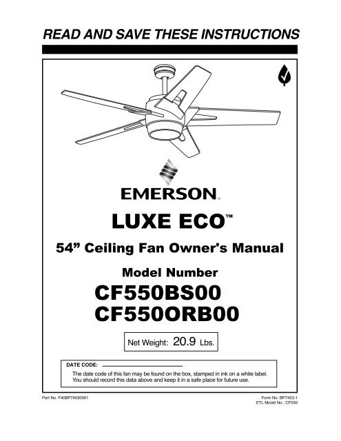
READ AND SAVE THESE INSTRUCTIONS<br />
LUXE ECO <br />
54” <strong>Ceiling</strong> <strong>Fan</strong> Owner's Manual<br />
Model Number<br />
CF550BS00<br />
CF550ORB00<br />
Net Weight: 20.9 Lbs.<br />
DATE CODE:<br />
The date code of this fan may be found on the box, stamped in ink on a white label.<br />
You should record this data above and keep it in a safe place for future use.<br />
Part No. F40<strong>BP7453</strong>0001 Form No. <strong>BP7453</strong>-1<br />
ETL Model No.: CF550
! WARNING<br />
WARNING: To avoid fire, shock, and serious personal injury, follow these instructions.<br />
Safety Instructions<br />
1. Read your owner’s manual carefully and keep it for future reference.<br />
2. Before servicing or cleaning unit, switch power off at service panel and lock service panel<br />
disconnecting means to prevent power from being switched on accidentally. When the service<br />
disconnecting means cannot be locked, securely fasten a warning device, such as a tag, to the<br />
service panel.<br />
3. Be careful of the fan and blades when cleaning, painting, or working near the fan. Always turn off<br />
the power to the ceiling fan before servicing.<br />
4. Do not put anything into the fan blades while they are turning.<br />
5. Do not operate reversing switch until fan blades have come to a complete stop.<br />
Additional Safety Instructions for Installation<br />
1. To avoid possible shock, be sure electricity is turned off at the fuse box before wiring, and do not<br />
operate fan without blades.<br />
2. All wiring must be in accordance with the National Electrical Codes “ANSI/NFPA 70-2011” and Local<br />
Electrical Codes. Use the National Electrical Code if Local Codes do not exist. The ceiling fan must<br />
be grounded as a precaution against possible electrical shock. Electrical installation should be<br />
made or approved by a licensed electrician.<br />
3. The outlet box and joist must be securely mounted and capable of reliably supporting at least<br />
50 pounds. Use only U.L. outlet boxes listed as “Acceptable for <strong>Fan</strong> Support of 22.7 kg. (50 lbs.) or<br />
less”, and use the mounting screws provided with the outlet box. Most outlet boxes commonly used<br />
for support of light fixtures are not acceptable for fan support and may need to be replaced. Consult<br />
a qualified electrician if in doubt.<br />
4. The downrod furnished with the fan provides the minimum recommended floor to fan blade<br />
clearance for an 8 foot ceiling.<br />
5. The fan must be mounted with the fan blades at least 7 feet from the floor to prevent accidental<br />
contact with the fan blades.<br />
6. Follow the recommended instructions for the proper method of wiring your ceiling fan. If you do not<br />
know enough about electrical wiring, have your fan installed by a licensed electrician.<br />
NOTE: All setscrews must be checked and re-tightened where necessary before installation.<br />
NOTE: This fan is suitable for use with solid-state speed controls.<br />
WARNING: To reduce the risk of fire or electric shock, this fan should only be used with fan speed<br />
control, Model No. FR-7861LM-06 manufactured by Rhine Electric Co., Ltd.<br />
WARNING: To avoid fire, shock or injury, do not use an <strong>Emerson</strong> or any other brand of control not<br />
specifically approved for this fan.<br />
WARNING: This product is designed to use only those parts supplied with this product and/or any<br />
accessories designated specifically for use with this product by <strong>Emerson</strong> Electric Co. Substitution of<br />
parts or accessories not designated for use with this product by <strong>Emerson</strong> Electric Co. could result in<br />
personal injury or property damage.<br />
WARNING: To reduce the risk of personal injury, do not bend the blade flange when installing the<br />
blade flanges, balancing the blades or cleaning the fan. Do not insert foreign objects in between<br />
rotating fan blades.<br />
WARNING: To reduce the risk of electrical shock, this fan must be installed with an isolating wall<br />
control/switch.<br />
This Manual Is Designed to Make it as Easy as Possible for You to Assemble,<br />
Install, Operate and Maintain Your <strong>Ceiling</strong> <strong>Fan</strong><br />
Tools Needed for Assembly<br />
One Phillips head screwdriver One stepladder<br />
One 1/4” blade screwdriver One wire stripper<br />
MATERIALS<br />
Wiring outlet box and box connectors must be of<br />
type required by the local code. The minimum wire<br />
would be a 3-conductor (2-wire with ground) of the<br />
following size:<br />
Installed Wire Length Wire Size A.W.G.<br />
Up to 50 ft. 14<br />
50-100 ft. 12<br />
!<br />
WARNING<br />
Before assembly your ceiling fan, refer to section<br />
on proper method of wiring your fan (page 7).<br />
If you feel you do not have enough wiring<br />
knowledge or experience, have your fan installed<br />
by a licensed electrician.<br />
2 ETL Model No.: CF550
!<br />
Do not install or use fan if any part is damaged or<br />
missing. Call Toll-Free:<br />
1-800-654-3545<br />
!<br />
This product is designed to use only those parts<br />
supplied with this product and/or any accessories<br />
designated specifically for use with this product by<br />
<strong>Emerson</strong> Electric Co. Substitution of parts or<br />
accessories not designated for use with this product<br />
by <strong>Emerson</strong> Electric Co. could result in personal<br />
injury or property damage.<br />
1. Check to see that you have received the following<br />
parts:<br />
NOTE: If you are uncertain of part description,<br />
refer to exploded view illustration.<br />
a. <strong>Fan</strong> motor assembly<br />
b. Light kit assembly<br />
c. One ceiling cover<br />
d. One coupler cover<br />
e. One glass shade<br />
f. One light kit cover plate<br />
g. Five fan blades<br />
h. One hanger bracket<br />
i. One hanger ball/4.5” downrod assembly<br />
j. One transmitter control with switch covers<br />
k. Two 50-watt (maximum) mini-candelabra base<br />
halogen lamps<br />
l. One loose parts bag containing:<br />
1. One clevis pin<br />
2. One hairpin clip<br />
3. Five 12 ga. wire connectors<br />
4. Two #8-32 x 1-1/4” threaded studs<br />
5. Two #8 external tooth lockwashers<br />
6. Two #8-32 knurled knobs<br />
7. Twenty-one #10-24 x .375” flat head<br />
blade screws<br />
8. Twenty-one #10 x .50” flat washers<br />
9. One balancing kit<br />
NOTE: Place the parts from the loose parts bags<br />
in a small container to keep them from being lost.<br />
If any parts are missing, contact your local retailer<br />
or catalog outlet for replacement before<br />
proceeding.<br />
Unpacking Instructions<br />
WARNING<br />
WARNING<br />
3<br />
2. Remove the lower styrofoam pad from the carton<br />
and place on a stable work surface.<br />
3. Remove the fan motor assembly from the<br />
protective plastic bag and position the fan motor<br />
assembly in the lower styrofoam packing so that<br />
the top for the motor is facing you. Place all carton<br />
contents on a soft protective surface.<br />
e. GLASS<br />
SHADE<br />
c. CEILING<br />
COVER<br />
h. HANGER<br />
BRACKET<br />
j. TRANSMITTER CONTROL<br />
WITH SWITCH COVERS<br />
g. FAN BLADES<br />
a. FAN MOTOR<br />
ASSEMBLY<br />
b. LIGHT KIT<br />
ASSEMBLY<br />
d. COUPLER<br />
COVER<br />
f. LIGHT KIT<br />
COVER PLATE<br />
h. HANGER BALL/<br />
4.5" DOWNROD<br />
i. LOOSE<br />
PARTS BAG<br />
k. 50-WATT MINI-<br />
CANDELABRA BASE<br />
HALOGEN LAMPS<br />
ETL Model No.: CF550
Your new ceiling fan will require a grounded electrical<br />
supply line of 120 volts AC, 60 Hz, 15 amp circuit.<br />
The outlet box must be securely anchored and<br />
capable of withstanding a load of at least 50 pounds.<br />
!<br />
To reduce the risk of fire, electrical shock, or<br />
personal injury, mount fan to outlet box marked<br />
“Acceptable for <strong>Fan</strong> Support of 22.7 kg. (50 lbs.) or<br />
less”, and use screws supplied with outlet box. Most<br />
outlet boxes commonly used for support of light<br />
fixtures are not acceptable for fan support and may<br />
need to be replaced. Consult a qualified electrician if<br />
in doubt.<br />
If your fan is to replace an existing ceiling light fixture,<br />
turn electricity off at the main fuse box at this time and<br />
remove the existing light fixture.<br />
Electrical Requirements<br />
WARNING<br />
4<br />
!<br />
WARNING<br />
Turning off wall switch is not sufficient. To avoid<br />
possible electrical shock, be sure electricity is<br />
turned off at the main fuse box before wiring. All<br />
wiring must be in accordance with National and<br />
Local codes and the ceiling fan must be properly<br />
grounded as a precaution against possible electrical<br />
shock.<br />
!<br />
WARNING<br />
To avoid fire or shock, follow all wiring instructions<br />
carefully. Any electrical work not described in these<br />
instructions should be done or approved by a<br />
licensed electrician.<br />
How to Put Your <strong>Ceiling</strong> <strong>Fan</strong> Together<br />
1. Remove the hanger ball by loosening the setscrew<br />
in the hanger ball until the ball falls freely down the<br />
downrod (Figure 3). Remove the pin from the<br />
downrod, then remove the hanger ball. Retain the<br />
pin and hanger ball for reinstallation in Step 5.<br />
2. Loosen setscrews in motor coupling. Separate,<br />
untwist and unkink the two 80” motor leads. Route<br />
the motor lead wires through the downrod. Insert<br />
the downrod into the motor coupling. Align the<br />
clevis pin holes in the downrod with the holes in the<br />
motor coupling. Install the clevis pin and secure<br />
with the hairpin clip (Figure 1). The clevis pin must<br />
go through the holes in the motor coupling and the<br />
holes in the downrod. Be sure to push the straight<br />
leg of the hairpin clip through the hole near the end<br />
of the clevis pin until the curved portion of the<br />
hairpin clip snaps around the clevis pin. The hairpin<br />
clip must be properly installed to prevent the clevis<br />
pin from working loose. Pull on the downrod to<br />
make sure the clevis pin is properly installed.<br />
3. While pulling up on the downrod, securely tighten<br />
the two setscrews in the motor coupling (Figure 2).<br />
NOTE: The setscrews must be properly installed<br />
as described above, or fan wobble could result.<br />
!<br />
WARNING<br />
It is critical that the clevis pin in the motor coupling<br />
is properly installed and the setscrews securely<br />
tightened. Failure to verify that the pin and setscrews<br />
are properly installed could result in the fan falling.<br />
Figure 1<br />
SETSCREW SETSCREW (2)<br />
CLEVIS CLEVIS PIN PIN<br />
Figure 2<br />
PIN<br />
HANGER<br />
BALL<br />
DOWNROD<br />
SETSCREW<br />
DOWNROD<br />
HAIRPIN<br />
CLIP<br />
MOTOR<br />
COUPLING MOTOR<br />
COUPLING<br />
ETL Model No.: CF550
How to Put Your <strong>Ceiling</strong> <strong>Fan</strong> Together (continued)<br />
4. Make sure the rubber grommet is properly installed<br />
onto the coupling cover then slide the coupler<br />
cover onto the downrod until it rests on top of the<br />
motor housing. Place the ceiling cover over<br />
the downrod. Be sure both the ceiling cover and<br />
the coupler cover are oriented correctly (Figure 3).<br />
5. Route the motor leads through the hanger ball.<br />
Reinstall the hanger ball (Figure 4) on the<br />
downrod. Reinstall the pin through the two holes in<br />
the downrod. Slide the ball upwards and align the<br />
ball so the pin is captured in the groove in the top<br />
of the hanger ball. Pull the hanger ball up tight<br />
against the pin and securely tighten the setscrew in<br />
the hanger ball. A loose setscrew could create fan<br />
wobble.<br />
!<br />
6. The fan comes with black and white leads that are<br />
80” long. Before installing fan, measure up<br />
approximately 6 to 9-inches above top of hanger<br />
ball/downrod assembly. Cut off excess leads and<br />
strip back insulation 1/2-inch from end of leads.<br />
7. Position one fan blade on the flange assembly of<br />
the motor assembly and secure by installing four<br />
#10-24 x .375” flat head screws and four #10 x .50”<br />
flat washers (supplied) (Figure 5).<br />
8. Install the remaining four fan blades using the<br />
same procedure.<br />
!<br />
WARNING<br />
It is critical that the pin in the hanger ball is properly<br />
installed and the setscrew securely tightened.<br />
Failure to verify that the pin and setscrew are<br />
properly installed could result in the fan falling.<br />
WARNING<br />
To reduce the risk of personal injury, do not bend the<br />
blade flange when installing the blade flanges,<br />
balancing the blades or cleaning the fan. Do not<br />
insert foreign objects in between rotating fan blades.<br />
NOTE: Take care not to scratch fan housing when<br />
installing blades.<br />
9. You have now completed the initial assembly of your<br />
new ceiling fan. You can now proceed with hanging<br />
and wiring your fan.<br />
5<br />
Figure 3<br />
HANGER BALL<br />
Figure 4<br />
#10-24 x .375" FLAT HEAD<br />
SCREWS (4 per blade)<br />
#10 x .50" FLAT<br />
WASHERS<br />
(4 per blade)<br />
Figure 5<br />
PIN<br />
CEILING<br />
COVER<br />
FAN BLADE<br />
BLADE FLANGE<br />
DOWNROD<br />
CEILING<br />
COVER<br />
RUBBER GROMMET<br />
COUPLER COVER<br />
FAN MOTOR<br />
ASSEMBLY<br />
SETSCREW<br />
DOWNROD<br />
ETL Model No.: CF550
!<br />
!<br />
How to Hang Your <strong>Ceiling</strong> <strong>Fan</strong><br />
The fan must be hung with at least 7' of clearance<br />
from floor to blades (Figure 6).<br />
!<br />
WARNING<br />
The outlet box and joist must be securely mounted and<br />
capable of supporting at least 50 lbs. Use only a U.L.<br />
outlet box listed as “Acceptable for <strong>Fan</strong> Support of 22.7<br />
kg. (50 lbs.) or less”.<br />
!<br />
WARNING<br />
WARNING<br />
To reduce the risk of fire, electrical shock, or personal<br />
injury, mount fan to outlet box marked “Acceptable for<br />
<strong>Fan</strong> Support of 22.7 kg. (50 lbs.) or less”, and use<br />
screws supplied with outlet box. Most outlet boxes<br />
commonly used for support of light fixtures are not<br />
acceptable for fan support and may need to be replaced.<br />
Consult a qualified electrician if in doubt.<br />
2. Carefully lift the fan and seat the hanger<br />
ball/downrod assembly onto the hanger bracket<br />
that was just attached to the outlet box (Figure 7).<br />
Rotate the entire fan assembly until the ball groove<br />
engages the anti-rotation tab. Be sure the groove in<br />
the ball engaged the anti-rotation tab on the hanger<br />
bracket (Figure 8).<br />
!<br />
Hanger bracket must seat firmly against outlet box. If<br />
the outlet box is recessed, remove wall board until<br />
bracket contacts box. If bracket and/or outlet box are<br />
not securely attached, the fan could wobble or fall.<br />
!<br />
!<br />
WARNING<br />
Turning off wall switch is not sufficient. To avoid<br />
possible electrical shock, be sure electricity is<br />
turned off at the main fuse box before wiring. All<br />
wiring must be in accordance with National and<br />
Local codes and the ceiling fan must be properly<br />
grounded as a precaution against possible electrical<br />
shock.<br />
1. With the branch circuit electricity turned off at the<br />
breaker panel or fuse box, securely attach the<br />
hanger bracket to the outlet box using the two<br />
screws supplied with the outlet box. (Figure 7.)<br />
WARNING<br />
WARNING<br />
Failure to seat tab in groove could cause damage to<br />
electrical wires and possible shock or fire hazard.<br />
WARNING<br />
To avoid possible fire or shock, do not pinch wires<br />
between the hanger ball/downrod assembly and<br />
hanger bracket.<br />
6<br />
AT LEAST<br />
7'<br />
Figure 6<br />
NOTE: CEILING COVER<br />
OMITTED FOR CLARITY.<br />
TWO SCREWS<br />
SUPPLIED WITH<br />
OUTLET BOX<br />
Figure 7<br />
CEILING<br />
FLOOR<br />
NOTE: CEILING COVER, SUPPLY WIRES AND FAN WIRES<br />
OMITTED FOR CLARITY.<br />
Figure 8<br />
OUTLET<br />
BOX<br />
TAB<br />
OUTLET<br />
BOX<br />
HANGER<br />
BRACKET<br />
HANGER<br />
BRACKET<br />
HANGER BALL/<br />
DOWNROD ASSEMBLY<br />
1-1/4" THREADED<br />
STUD (2)<br />
ETL Model No.: CF550
How to Wire Your <strong>Ceiling</strong> <strong>Fan</strong><br />
If you feel that you do not have enough electrical<br />
wiring knowledge or experience, have your fan<br />
installed by a licensed electrician.<br />
!<br />
Turning off wall switch is not sufficient. To avoid<br />
possible electrical shock, be sure electricity is<br />
turned off at the main fuse box before wiring. All<br />
wiring must be in accordance with National and<br />
Local codes and the ceiling fan must be properly<br />
grounded as a precaution against possible electrical<br />
shock.<br />
1. Connect the green grounding lead from the hanger<br />
ball and the green grounding lead from the hanger<br />
bracket to the grounding conductor of supply (this<br />
may be a bare wire or wire with green colored<br />
insulation). Securely connect wires with wire<br />
connectors supplied.<br />
2. Securely connect the fan motor white wire to the<br />
supply white (neutral) wire using wire connector<br />
supplied (Figure 9). Securely connect the fan motor<br />
black wire to the supply black (hot) wire using wire<br />
connector supplied (Figure 9). After connections<br />
have been made, turn leads upward and carefully<br />
push leads into the outlet box, with the white and<br />
green leads on one side of the outlet box and the<br />
black leads on the other side of the outlet box.<br />
!<br />
WARNING<br />
WARNING<br />
Check to see that all connections are tight, including<br />
ground, and that no bare wire is visible at the wire<br />
connectors, except for the ground wire. Do not<br />
operate fan until blades are in place. Noise and fan<br />
damage could result.<br />
3. Screw the two threaded studs (supplied) into the<br />
tapped holes in the hanger bracket.<br />
4. Lift the ceiling cover up to the threaded studs and<br />
turn until studs protrude through the holes in the<br />
ceiling cover (Figure 10).<br />
5. Secure the ceiling cover in place by sliding<br />
lockwashers over the threaded studs and installing<br />
the two knurled knobs (supplied). (Figure 10).<br />
Tighten the knurled knobs securely until the ceiling<br />
cover fits snugly against the ceiling and the hole in<br />
the ceiling cover is clear of the downrod.<br />
!<br />
WARNING<br />
To avoid possible fire or shock, make sure that the<br />
electrical wires are completely inside the outlet box<br />
and not pinched between the ceiling cover and the<br />
ceiling.<br />
GROUND<br />
WIRE<br />
LISTED<br />
WIRE<br />
CONNECTOR (3)<br />
BLACK<br />
FAN WIRE<br />
GREEN WIRE<br />
(GROUND) FROM<br />
HANGER BRACKET<br />
GREEN WIRE<br />
(GROUND) FROM<br />
HANGER BALL<br />
Figure 9<br />
Figure 10<br />
WHITE SUPPLY<br />
(NEUTRAL)<br />
WHITE FAN<br />
WIRE<br />
BLACK SUPPLY<br />
(HOT)<br />
NOTE: CEILING COVER<br />
OMITTED FOR CLARITY.<br />
CEILING COVER<br />
THREADED STUDS (2)<br />
LOCKWASHERS (2)<br />
KNURLED KNOBS (2)<br />
7 ETL Model No.: CF550
Lower Light Kit Assembly<br />
1. With the fan assembly safely installed on the<br />
mounting bracket, install the lower light kit as<br />
follows.<br />
2. Remove one screw (retain for future use) and<br />
loosen the two other screws in the motor housing<br />
for installation of the light kit assembly (Figure 11).<br />
3. Connect the white wire from the ceiling fan<br />
assembly to the white wire of the light kit assembly<br />
(Figure 11). Connect the black wire from the ceiling<br />
fan assembly to the black wire of the light kit<br />
assembly.<br />
!<br />
WARNING<br />
Make sure all wires and connectors are tucked under<br />
the light kit assembly and not pinched between light<br />
kit assembly and fan motor assembly.<br />
4 Position the light kit assembly onto the fan motor<br />
assembly, safely tucking all wires and connectors<br />
inside the light kit assembly.<br />
5. Engage the two key slots on the light kit assembly<br />
with two loosened screws in motor housing<br />
assembly. Rotate the light kit assembly clockwise<br />
to engage the two screws into both slots and<br />
tighten securely. Install the previously removed<br />
screw into the remaining hole of the light kit<br />
assembly, attaching it to the fan motor assembly<br />
securely (Figure 12).<br />
6. If no light kit is to be used, screw the light kit<br />
cover plate into the center hole of the light kit<br />
assembly. Rotate the light kit cover plate<br />
clockwise until fully installed (Figure 13).<br />
CAUTION: To avoid risk of burns or other injury,<br />
assure power is off before attempting to install or<br />
replace the 50-watt (max.) mini-candelabra base<br />
halogen lamps. Halogen lamps are very hot and<br />
can cause burns. Allow the lamps to cool<br />
sufficiently before handling.<br />
CAUTION: To not touch 50-watt (max.) minicandelabra<br />
base halogen lamps with bare hands.<br />
Fingerprints may result in shorter lamp life.<br />
Remove fingerprints with alcohol.<br />
7. If light kit assembly is to be used as a down<br />
light, screw in two 50-watt (maximum) minicandelabra<br />
base halogen lamps (supplied) into the<br />
light kit assembly light sockets (Figure 14).<br />
8. Place the light kit glass shade into the light kit<br />
assembly, aligning the three flat areas on the top<br />
flange of the glass shade with the three raised<br />
studs in the light kit assembly. Then turn the glass<br />
shade clockwise until it stops and is secure<br />
(Figure 14).<br />
NOTE: Periodically check that the glass bowl is<br />
seated fully clockwise in the light kit assembly.<br />
9. Installation of your ceiling fan is now complete.<br />
Proceed with installation of the wall control.<br />
Please call <strong>Emerson</strong> technical support at<br />
1-800-654-3545 if you have any questions<br />
about installation and operation of this ceiling fan.<br />
8<br />
MOTOR HOUSING<br />
BLACK WIRE<br />
MOTOR<br />
HOUSING<br />
WHITE WIRE<br />
REMOVE & RETAIN<br />
ONE SCREW FROM<br />
MOTOR HOUSING<br />
LIGHT KIT WHITE WIRE<br />
LIGHT KIT BLACK WIRE<br />
Figure 11<br />
Figure 12<br />
Figure 13<br />
LIGHT KIT<br />
SOCKETS (2)<br />
Figure 14<br />
LIGHT KIT ASSEMBLY<br />
50-WATT BASE<br />
LAMPS (2)<br />
MOTOR HOUSING<br />
ASSEMBLY<br />
LOOSEN TWO SCREWS<br />
WIRE CONNECTORS<br />
MOTOR<br />
HOUSING<br />
ASSEMBLY<br />
LIGHT KIT<br />
ASSEMBLY<br />
REINSTALL SCREW<br />
LIGHT KIT<br />
ASSEMBLY<br />
CENTER HOLE<br />
LIGHT KIT<br />
ASSEMBLY<br />
LIGHT KIT<br />
COVER PLATE<br />
LIGHT KIT<br />
ASSEMBLY<br />
RAISED<br />
STUDS (3)<br />
GLASS SHADE<br />
FLAT AREAS (3)<br />
LIGHT KIT<br />
GLASS SHADE<br />
ETL Model No.: CF550
General<br />
Your <strong>Emerson</strong> <strong>Ceiling</strong> <strong>Fan</strong>/Light Control consists of<br />
wall mounted transmitter and a receiver which is preinstalled<br />
inside the motor assembly. The remote<br />
control is designed to separately control your ceiling<br />
fan speed and light intensity.<br />
Code switches in the transmitter and receiver may be<br />
set in 32 different positions. If your fan and light go on<br />
and off without using your control, you may be getting<br />
interference from other remote units such as garage<br />
door openers, car alarms or security systems. To<br />
remedy this situations, simply change the code switch<br />
combination in your transmitter.<br />
Your wall control has code switches which must be<br />
set in one of 32 possible code combinations (Figure<br />
15). The five levers (numbered 1, 2, 3, 4, and 5) on<br />
the switches are factory-set in the ON (up) position.<br />
Change the switch settings as follows:<br />
1. Slide the five switch levers in the wall control to<br />
your choice of ON (up) or down positions. Use a<br />
ball-point pen or small screwdriver and slide the<br />
levers firmly up or down.<br />
2. The sixth switch marked ON and I is for dimming<br />
control of lights: Set switch to ON to allow for<br />
dimming of the lights. Set switch to I for no<br />
dimming of the lights such as for fluorescent bulbs.<br />
Wall Control Procedures<br />
Wall Control Installation (continued)<br />
SINGLE-POLE INSTALLATION<br />
!<br />
WARNING<br />
Turning off wall switch is not sufficient. To avoid<br />
possible electrical shock, be sure electricity is<br />
turned off at the main fuse or circuit breaker box<br />
before wiring. All wiring must be in accordance with<br />
National and Local codes and the ceiling fan must be<br />
properly grounded as a precaution against possible<br />
electrical shock.<br />
CAUTION: To reduce the risk of electrical shock,<br />
disconnect the electrical supply circuit before<br />
installing the fan, light kit or receiver.<br />
Preset Memory Feature<br />
Your <strong>Emerson</strong> receiver is equipped with a preset<br />
memory feature. If the AC supply to the receiver is<br />
powered through a wall switch, when the switch is<br />
turned OFF, the control will remember the light<br />
intensity and fan speed. When the switch is turned<br />
back ON the light and fan will resume operation as<br />
they were prior to the switch being turned OFF.<br />
Setting Operating Frequency of Wall Control<br />
WALL<br />
CONTROL<br />
Figure 15<br />
HOT BLK<br />
NEUTRAL<br />
RECEIVER LOCATED<br />
ON TOP OF THE<br />
CEILING FAN<br />
Figure 16<br />
HI<br />
LIGHT<br />
MED<br />
LOW<br />
FAN OFF<br />
EMERSON ®<br />
OFF<br />
ON<br />
WALL CONTROL<br />
CODE SWITCHES<br />
9 ETL Model No.: CF550<br />
ON<br />
1 2 3 4 5 I<br />
FAN/LIGHT<br />
WALL CONTROL<br />
BLACK<br />
BLACK<br />
CODE<br />
SWITCHES<br />
LOAD<br />
GROUND
Wall Control Installation (continued)<br />
NOTE: Make all wiring connections using wire<br />
connectors (supplied). Make sure that all<br />
connections are tight, including ground, and that<br />
no bare wire is visible at the wire connectors,<br />
except for the ground wire.<br />
1. Disconnect electrical power to the branch circuit at<br />
the circuit breaker or fuse box before attempting to<br />
install the ceiling fan wall control into the outlet box.<br />
Do not connect any neutral (white) wire to this<br />
control. Incorrect wiring will damage this control.<br />
2. Remove faceplate and screws from existing wall<br />
control. Pull control out from the wall box.<br />
Determine the “hot” wire and the “load” wire and<br />
disconnect these wires from control. Do not attempt<br />
to disconnect any wires not already connected to<br />
existing control.<br />
3. Before installing wall control, place wall control in<br />
“OFF” mode by pushing “ON/OFF” switch to the<br />
“OFF” position.<br />
4. Connect one black wire of wall control to the “hot”<br />
wire. Securely connect wires with wire connectors<br />
supplied (Figure 17).<br />
5. Connect one black wire of wall control to the “load”<br />
(black) wire in wall box. Securely connect wires<br />
with wire connector supplied.<br />
3-WAY INSTALLATION<br />
!<br />
WARNING<br />
(One fan controlled by two different wall controls)<br />
(See Figures 18 and 19.)<br />
!<br />
Turning off wall switch is not sufficient. To avoid<br />
possible electrical shock, be sure electricity is<br />
turned off at the main fuse or circuit breaker box<br />
before wiring. All wiring must be in accordance with<br />
National and Local codes and the ceiling fan must be<br />
properly grounded as a precaution against possible<br />
electrical shock.<br />
1. Disconnect electrical power to the branch circuit at<br />
the circuit breaker or fuse box before attempting to<br />
install the ceiling fan wall control into the outlet<br />
box.<br />
!<br />
WARNING<br />
WARNING<br />
Do not connect any neutral (white) wire to this<br />
control. Incorrect wiring will damage this control.<br />
Figure 17<br />
SCREWS (2)<br />
!<br />
SWITCH COVER<br />
DECORATIVE WALL PLATE<br />
FAN/LIGHT WALL<br />
CONTROL WALL BOX<br />
WARNING<br />
Check to see that all connections are tight and that<br />
no bare wires are visible at the wire connectors.<br />
6. Screw wall control into wall box using the supplied<br />
screws. Leave wall control in “OFF” mode until fan<br />
installation is completed.<br />
7. The wall control is supplied with a white, ivory, and<br />
almond color switch covers. Choose the finish that<br />
best suits your needs and snap the cover onto the<br />
wall control (Figure 17).<br />
8. Install decorator wall plate using the two screws<br />
provided with wall plate. Leave wall control in<br />
“OFF” mode until fan installation is completed<br />
(Figure 17).<br />
10 ETL Model No.: CF550<br />
BLK<br />
BLACK<br />
HOT<br />
TO 120VAC SOURCE<br />
TO LOAD<br />
GROUND<br />
NEUTRAL<br />
WIRES<br />
2. At all wall box locations remove faceplates and<br />
screws from existing controls. Pull controls out<br />
from wall boxes and determine which wall box<br />
contains the “hot” lead and which wall box contains<br />
the “load” wire. Also, identify traveler wires which<br />
are common to both wall boxes. Disconnect wires<br />
from existing controls only. Do not attempt to<br />
disconnect any wires not already connected to<br />
existing controls.<br />
3. Before installing wall control, place wall control in<br />
“OFF” mode by pushing “ON/OFF” switch to the<br />
“OFF” position.<br />
4. Install a wall control in the wall box containing the<br />
“hot” wire first. Connect the black wire of the wall<br />
control to the “hot” wire. Securely connect wires<br />
with wire connectors supplied.<br />
5. Connect one black wire of the wall control to both<br />
remaining traveler wires in the wall box and secure<br />
with wire connector supplied.<br />
NOTE: Retrofit 3-way installations are likely to<br />
include two traveler wires between the two wall<br />
boxes (Figure 19). In new construction, only one<br />
traveler wire Is required (See Figure 18).
Wall Control Installation (continued)<br />
! WARNING<br />
STANDARD WIRING FOR EXISTING<br />
Check to see that all connections are tight and that<br />
no bare wires are visible at the wire connectors.<br />
6. Screw wall control into wall box using the supplied<br />
screws. Leave wall control in “OFF” mode until<br />
fan installation is completed.<br />
7. The wall control is supplied with a white, ivory, and<br />
almond color switch covers. Choose the finish that<br />
best suits your needs and snap the cover onto the<br />
wall control (Figure 17).<br />
8. Next, install the other wall control into the wall box<br />
containing the load wire. Connect the black wire of<br />
the wall control to the traveler wire(s) already<br />
connected to the black wire (in the other wall box).<br />
Secure with wire connectors supplied.<br />
9. Connect one black wire of the wall control to the<br />
“load” (black) wire and secure with wire connector<br />
supplied.<br />
10.Restore electricity to your ceiling fan from the main<br />
fuse box or breaker panel.<br />
3-WAY WIRING DIAGRAM:<br />
NEW CONSTRUCTION<br />
HOT<br />
BLACK<br />
EMERSON ®<br />
HI<br />
LIGHT<br />
MED<br />
LOW<br />
FAN OFF<br />
OFF<br />
ON<br />
SW605<br />
FAN/LIGHT<br />
WALL<br />
CONTROL<br />
TRAVELER<br />
NEUTRAL WIRE<br />
RECEIVER LOCATED<br />
ON TOP OF THE<br />
CEILING FAN<br />
Figure 18<br />
BLK<br />
EMERSON ®<br />
HI<br />
LIGHT<br />
MED<br />
LOW<br />
FAN OFF<br />
OFF<br />
ON<br />
BLK<br />
LOAD<br />
BLACK GROUND<br />
IMPORTANT CARE INSTRUCTIONS<br />
for your <strong>Ceiling</strong> <strong>Fan</strong><br />
Periodic cleaning of your new ceiling fan is the only<br />
maintenance that is needed.<br />
When cleaning, use only a soft brush or lint free cloth<br />
to avoid scratching the finish.<br />
Abrasive cleaning agents are not required and should<br />
be avoided to prevent damage to finish.<br />
3-WAY CONTROLS<br />
Figure 19<br />
HOT BLK<br />
HOT BLK<br />
FAN/LIGHT<br />
WALL CONTROL<br />
Maintenance<br />
EXISTING<br />
WALL CONTROL<br />
TRAVELER WIRES<br />
®<br />
EMERSON EMERSON®<br />
OFF<br />
HI<br />
MED<br />
LOW<br />
FAN OFF<br />
LIGHT<br />
ON<br />
BLK BLK<br />
TRAVELER WIRES<br />
BLK<br />
11 ETL Model No.: CF550<br />
OFF<br />
HI<br />
MED<br />
LOW<br />
FAN OFF<br />
LIGHT<br />
ON<br />
BLACK<br />
LOAD<br />
3-WAY WIRING DIAGRAM: RETROFIT<br />
!<br />
WARNING<br />
BLACK<br />
LOAD<br />
Do not use water when cleaning your ceiling fan. It<br />
could damage the motor or the blades and create the<br />
possibility of an electrical shock.
Programming the Receiver Operating Frequency &<br />
High Speed Conditioning of <strong>Fan</strong> Control<br />
IMPORTANT: <strong>Ceiling</strong> fan blades MUST be<br />
installed before high speed conditioning<br />
can begin.<br />
1. Within 1 minute of restoring electricity to the<br />
ceiling fan, push and hold the fan OFF button ( )<br />
for 3 to 5 seconds to set the code in the receiver.<br />
The ceiling fan lights (if installed) will blink to<br />
indicate the transmitted has been paired with the<br />
receiver.<br />
IMPORTANT: Immediately after successful<br />
pairing, the ceiling fan will automatically<br />
begin high speed conditioning of the<br />
motor. During conditioning, the electronic<br />
motor control software is calculating<br />
speeds for the 2nd through 5th speed<br />
settings based on the blades that were<br />
installed on the fan.<br />
2. The fan will run for approximately 2 minutes in the<br />
upward direction then reverse direction to down<br />
flow and run an additional 2 minutes. When<br />
conditioning is complete, the fan will come to<br />
complete stop.<br />
!<br />
<strong>Fan</strong> installation must be completed, including the<br />
installation of the fan blades, before testing the remote<br />
control.<br />
Using Your <strong>Ceiling</strong> <strong>Fan</strong><br />
WARNING<br />
Your wall control has full control of your fan and light.<br />
1.To set the desired fan speed, press the ( ) button<br />
to decrease the speed and the ( ) to increase the<br />
speed. The LED display will light up to indicate the<br />
new speed selected.<br />
2.To turn the light on and off, press and release the<br />
LIGHT ( ) button. To set the light intensity, press<br />
and hold the LIGHT ( ) button. The light will turn<br />
on at the light intensity previously selected.<br />
3.Your wall control comes complete with your choice<br />
of three wall cover plates; ivory, white and light<br />
almond.<br />
4. If airflow is desired in the opposite direction, press<br />
the ( ) button on the wall control. The fan must<br />
be operating at any speed for the reverse button to<br />
function. The blades will turn in the opposite<br />
direction and reverse the airflow.<br />
12<br />
IMPORTANT: Do not interrupt the<br />
conditioning until the fan comes to a<br />
complete stop in approximately 5 minutes.<br />
All functions of the control will be rejected<br />
during conditioning.<br />
3. High speed conditioning is now complete.<br />
4. If programming is unsuccessful, retry the above<br />
instructions after cycling the wall control ON/OFF<br />
switch to restart the 1 minute programming time<br />
period.<br />
5. If still unsuccessful, shut off the electricity at the<br />
fuse box or breaker panel and change the wall<br />
control frequency (page 9). After changing the<br />
frequency settings, repeat instruction #1 of this<br />
section within one minute of restoring the<br />
electricity.<br />
Figure 20<br />
POWER<br />
INDICATOR<br />
LIGHT<br />
FAN<br />
DIRECTION<br />
FAN<br />
BUTTON<br />
LIGHT<br />
BUTTON<br />
HIGH TO LOW<br />
SPEED BUTTONS<br />
ON/OFF SWITCH<br />
O = OFF / — = ON<br />
ETL Model No.: CF550
1. <strong>Ceiling</strong> <strong>Fan</strong>/Light Controls (see store or catalog).<br />
2. Downrod Extension Kits (see store or catalog).<br />
!<br />
!<br />
WARNING<br />
The use of any other control not specifically<br />
approved for this fan could result in fire, shock and<br />
personal injury.<br />
Accessories<br />
Trouble Shooting<br />
This product is designed to use only those parts<br />
supplied with this product and/or any accessories<br />
designated specifically for use with this product by<br />
<strong>Emerson</strong> Electric Co. Substitution of parts or<br />
accessories not designated for use with this product<br />
by <strong>Emerson</strong> Electric Co. could result in personal<br />
injury or property damage.<br />
WARNING: For your own safety, turn off power at fuse box or circuit breaker before trouble shooting your fan.<br />
TROUBLE PROBABLE CAUSE SUGGESTED REMEDY<br />
1. <strong>Fan</strong> will not start. 1. Fuse or circuit breaker blown. 1. Check main and branch circuit fuses or circuit<br />
breakers.<br />
2. Loose power line connections to the fan, 2. Check line wire connections to fan and switch<br />
or loose switch wire connections in the wire connections in the switch housing.<br />
switch housing. ! WARNING: Make sure main power is<br />
turned OFF.<br />
3. <strong>Fan</strong> Wall Control is OFF. 3. Turn ON <strong>Fan</strong> Wall Control.<br />
2. <strong>Fan</strong> sounds noisy. 1. Blades not attached to fan. 1. Attach blades to fan before operating.<br />
2. Loose screws in motor housing. 2. Check to make sure all screws in motor housing<br />
are snug (not over-tight).<br />
3. Screws securing fan blades to 3. Check to make sure the screws which attach<br />
fan blade flanges are loose. the fan blades to the blade flanges are tight.<br />
4. Wire connectors inside light kit housing 4. Check to make sure wire connectors in light kit<br />
rattling. housing are not rattling against each other or<br />
against the interior wall of the switch housing.<br />
! WARNING: Make sure main power is<br />
turned OFF.<br />
WARNING<br />
3. <strong>Fan</strong> wobbles 1. Setscrew in motor coupling is loose. 1. Tighten both setscrews securely in the motor<br />
excessively. coupling.<br />
2. Setscrew in hanger ball/downrod 2. Tighten the setscrew in the hanger ball/<br />
assembly is loose. downrod assembly.<br />
3. <strong>Fan</strong> blade flanges are loose or not properly 3. Check to be sure the fan blade flanges are seated<br />
properly seated into the blade holders. firmly and uniformly into the blade holders.<br />
If blades are seated incorrectly, loosen the<br />
blade screws and retighten according to the<br />
procedure in the section on "How to Put<br />
Your <strong>Ceiling</strong> <strong>Fan</strong> Together".<br />
4. Hanger bracket and/or ceiling outlet 4. Tighten the hanger bracket screws to the outlet<br />
box is not securely fastened. box, and/or secure outlet box.<br />
5. <strong>Fan</strong> blades out of balance. 5. Interchanging an adjacent (side-by-side) blade<br />
pair can redistribute the weight and result in<br />
smoother operation.<br />
!<br />
13 ETL Model No.: CF550
4<br />
17<br />
19<br />
12<br />
Repair Parts<br />
10<br />
11<br />
18<br />
15<br />
1<br />
16<br />
13<br />
7<br />
14<br />
6<br />
8<br />
9<br />
3<br />
2<br />
14 ETL Model No.: CF550<br />
5<br />
20
Repair Parts Listing<br />
Key Model Number<br />
No. Description CF550BS00 CF550ORB00<br />
* Hanger Ball Assembly, 761655-17 761655-32<br />
Consisting of:<br />
1 Hanger Bracket — —<br />
2 Hanger Ball — —<br />
3 Downrod (4.5”) — —<br />
* Parts Bag Containing: 764255 764255-1<br />
4 Wire Connector (5) — —<br />
5 Pin, Clevis (1) — —<br />
6 Clip, Hairpin (1) — —<br />
7 Threaded Stud, #8-32 x 1-1/4” (2) — —<br />
8 Lockwasher, External Tooth #8 (2) — —<br />
9 Knurled Knob, #8-32 (2) — —<br />
10 Screw, Flat Head Blade, #10-24 x .375” (21) — —<br />
11 Washer, Flat, #10 x .50” (21) — —<br />
12 Balancing Kit (1) — —<br />
13 Cover, <strong>Ceiling</strong> (1) 764240-BS 764240-ORB<br />
14 Coupler Cover (1) 762463-BS 762463-ORB<br />
15 Light Kit Assembly (1) 764250-BS 764250-ORB<br />
16 Light Kit Cover Plate (1) 764256-BS 764256-ORB<br />
17 Light Kit Glass Shade (1) 764253-OM 764253-OM<br />
18 Blades (set of 5) 764248-DM 764248-WA<br />
19 Wall Control,Transmitter 6-Speed SW605 SW605<br />
20 Control, Receiver 764087-1 764087-1<br />
— Owner's Manual <strong>BP7453</strong>-1 <strong>BP7453</strong>-1<br />
Before discarding packaging material, be certain all parts have been removed.<br />
HOW TO ORDER REPAIR PARTS<br />
WHEN ORDERING REPAIR PARTS, ALWAYS GIVE THE FOLLOWING INFORMATION:<br />
• PART NUMBER • PART DESCRIPTION • NAME OF ITEM • MODEL NUMBER<br />
For repair parts, phone 1-800-654-3545.<br />
15<br />
ETL Model No.: CF550
<strong>Emerson</strong> Air Comfort <strong>Ceiling</strong> <strong>Fan</strong> Limited Warranty<br />
What The Limited Warranty Covers:<br />
This limited warranty is offered by Air Comfort Products division of <strong>Emerson</strong> Electric Co. ("<strong>Emerson</strong>" "we" or "us") located at the address stated below to the original retail<br />
purchaser ("you" or "your") of an <strong>Emerson</strong> Air Comfort <strong>Ceiling</strong> <strong>Fan</strong> product ("<strong>Emerson</strong> <strong>Ceiling</strong> <strong>Fan</strong>") and covers the motor and the other components and accessories of the<br />
<strong>Emerson</strong> <strong>Ceiling</strong> <strong>Fan</strong> against all defects in workmanship and materials.<br />
What The Period Of Coverage Is:<br />
This limited warranty will cover the <strong>Emerson</strong> <strong>Ceiling</strong> <strong>Fan</strong> motor for the expected lifetime of your <strong>Emerson</strong> <strong>Ceiling</strong> <strong>Fan</strong> (when operated in accordance with your Owner's Manual<br />
or other instructions provided by <strong>Emerson</strong> to you with the <strong>Emerson</strong> <strong>Ceiling</strong> <strong>Fan</strong>). All other components and accessories of the <strong>Emerson</strong> <strong>Ceiling</strong> <strong>Fan</strong> are covered by this limited<br />
warranty for a period of one (1) year from its date of original retail purchase. ANY IMPLIED WARRANTY, INCLUDING WITHOUT LIMITATION, ANY IMPLIED WARRANTY OF<br />
MERCHANTABILITY OR FITNESS FOR A PARTICULAR PURPOSE THAT IS AVAILABLE TO YOU UNDER THE LAWS OF YOUR STATE OR PROVINCE SHALL COVER THE<br />
MOTOR FOR THE EXPECTED LIFETIME OF THE MOTOR (SUBJECT TO PROPER USE), AND FOR ONE YEAR WITH RESPECT TO COMPONENTS AND ACCESSORIES.<br />
No Other Express or Implied Warranty Applies:<br />
THE LIMITED WARRANTIES PROVIDED ABOVE ARE THE SOLE AND EXCLUSIVE WARRANTIES PROVIDED BY EMERSON TO YOU FOR YOUR EMERSON CEILING FAN, AND<br />
ARE IN LIEU OF ALL OTHER WARRANTIES, WRITTEN OR ORAL, EXPRESS OR IMPLIED, WHETHER ARISING BY OPERATION OF LAW OR OTHERWISE, WHETHER OR NOT<br />
THE PURPOSE HAS BEEN DISCLOSED AND WHETHER OR NOT THE EMERSON CEILING FAN HAS BEEN SPECIFICALLY DESIGNED OR MANUFACTURED FOR YOUR USE OR<br />
PURPOSE. EMERSON HEREBY DISCLAIMS ANY AND ALL IMPLIED WARRANTIES, INCLUDING WITHOUT LIMITATION, IMPLIED WARRANTIES OF MERCHANTABILITY OR<br />
FITNESS FOR A PARTICULAR PURPOSE FOR COMPONENTS AND ACCESSORIES AS OF THE EXPIRATION OF THE ONE YEAR WARRANTY PERIOD FOR SUCH COMPONENTS<br />
AND ACCESSORIES. IMPLIED WARRANTIES OF MERCHANTABILITY OR FITNESS FOR A PARTICULAR PURPOSE FOR THE MOTOR PORTION OF THE EMERSON CEILING<br />
FAN ARE LIKEWISE DISCLAIMED BY EMERSON AT SUCH TIME THAT THE EXPECTED LIFETIME OF THE EMERSON CEILING FAN UNDER NORMAL USAGE HAS BEEN<br />
REACHED. EXCLUSIONS OR LIMITATIONS OF IMPLIED WARRANTIES MAY VARY FROM STATE TO STATE AND PROVINCE TO PROVINCE SO THE ABOVE LIMITATIONS<br />
MAY NOT APPLY TO YOU.<br />
What We Will Do To Correct Problems:<br />
If during the one (1) year warranty period the motor or any component or accessory of your <strong>Emerson</strong> <strong>Ceiling</strong> <strong>Fan</strong> is defective in materials or workmanship, or if during the<br />
expected lifetime of the <strong>Emerson</strong> <strong>Ceiling</strong> <strong>Fan</strong> (when used in accordance with the User Manual or other instructions) the motor is defective in materials or workmanship, you<br />
must contact <strong>Emerson</strong> during the applicable warranty period. If the defect is covered by warranty, <strong>Emerson</strong> will repair or replace the defective motor, component or other<br />
accessory at no charge to you. If repair of the motor, component or accessory is not practical or possible within a reasonable time and no replacement <strong>Emerson</strong> <strong>Ceiling</strong> <strong>Fan</strong><br />
can be provided, <strong>Emerson</strong> will refund to you the actual purchase price of your <strong>Emerson</strong> <strong>Ceiling</strong> <strong>Fan</strong>. We will ship the repaired or the replacement <strong>Emerson</strong> <strong>Ceiling</strong> <strong>Fan</strong> to you at<br />
no charge, but you are responsible for all costs of removal and reinstallation of your <strong>Emerson</strong> <strong>Ceiling</strong> <strong>Fan</strong>.<br />
How You Can Receive Warranty Service:<br />
You must be the original retail purchaser and have proof of your purchase of the <strong>Emerson</strong> <strong>Ceiling</strong> <strong>Fan</strong> to obtain your remedy under this limited warranty. You can return your<br />
<strong>Emerson</strong> <strong>Ceiling</strong> <strong>Fan</strong> to your place of purchase, or you can call <strong>Emerson</strong> Customer Service at 1-800-237-6511 to obtain a return authorization and service identification tag. In<br />
order for us to confirm that your <strong>Emerson</strong> <strong>Ceiling</strong> <strong>Fan</strong> is still under warranty, please retain your receipt or other proof of purchase and have that information readily available<br />
when returning your <strong>Emerson</strong> <strong>Ceiling</strong> <strong>Fan</strong> to your place of purchase, or upon calling <strong>Emerson</strong> Customer Service. If you call <strong>Emerson</strong> Customer Service, prior to your call please<br />
be prepared to provide all model numbers shown on your <strong>Emerson</strong> <strong>Ceiling</strong> <strong>Fan</strong>. Once we have processed your return authorization request, we will provide you with a postage<br />
paid return label which should be affixed to the <strong>Emerson</strong> <strong>Ceiling</strong> <strong>Fan</strong> package you ship to the address listed at the end of this limited warranty. The return label will be sent to<br />
the mailing address you provide to us by phone.<br />
What Is Not Covered:<br />
This limited warranty does not extend to and expressly excludes:<br />
• The glass globes and light bulbs of your <strong>Emerson</strong> <strong>Ceiling</strong> <strong>Fan</strong>,<br />
• Loss or damage to the motor or any component or accessory caused by normal wear and tear, rather than due to defects in materials or workmanship,<br />
• Loss or damage resulting from conditions beyond our reasonable control, including without limitation, repairs not made at our factory or authorized service center, use of<br />
parts or accessories not provided to you as part of this warranty by our factory or authorized service center, mishandling, unreasonable use, misuse, abuse, modifications<br />
or other damage caused by you or a third party to your <strong>Emerson</strong> <strong>Ceiling</strong> <strong>Fan</strong> while not in our possession,<br />
• Loss or damage resulting from improper installation, or other failure to comply with instructions in your Owner's Manual.<br />
This limited warranty is deemed null and void upon the occurrence of either of the following events:<br />
• You cease to own the <strong>Emerson</strong> <strong>Ceiling</strong> <strong>Fan</strong> product, or<br />
• The <strong>Emerson</strong> <strong>Ceiling</strong> <strong>Fan</strong> is moved from its original point of installation.<br />
This limited warranty is only valid within the 50 United States, the District of Columbia, and Canada. No other written or oral warranties apply, and no employee, agent, dealer<br />
or other person is authorized to give any warranties on behalf of Air Comfort Products or <strong>Emerson</strong> Electric Co.<br />
Limitation of Liability<br />
REPAIR, REPLACEMENT OR A REFUND ARE THE EXCLUSIVE REMEDIES AVAILABLE TO YOU UNDER THIS LIMITED WARRANTY. TO THE EXTENT PERMITTED BY LAW, IN<br />
NO EVENT SHALL EMERSON OR ANY EMERSON AUTHORIZED DEALER BE LIABLE FOR ANY INCIDENTAL, SPECIAL, INDIRECT, OR CONSEQUENTIAL DAMAGES,<br />
INCLUDING ANY ECONOMIC LOSS, WHETHER RESULTING FROM NONPERFORMANCE, USE, MISUSE OR INABILITY TO USE THE EMERSON CEILING FAN OR FOR THE<br />
NEGLIGENCE OF EMERSON OR AN EMERSON AUTHORIZED DEALER. EMERSON SHALL NOT BE LIABLE FOR DAMAGES CAUSED BY DELAY IN PERFORMANCE AND IN NO<br />
EVENT, REGARDLESS OF THE FORM OF THE CLAIM OR CAUSE OF ACTION (WHETHER BASED IN CONTRACT, INFRINGEMENT, NEGLIGENCE, STRICT LIABILITY, OTHER<br />
TORT OR OTHERWISE), SHALL EMERSON'S OR ANY EMERSON AUTHORIZED AGENT'S LIABILITY TO YOU OR ANY INDIVIDUAL USING THE EMERSON CEILING FAN<br />
EXCEED THE PRICE PAID BY THE ORIGINAL OWNER FOR THE EMERSON CEILING FAN. The term "consequential damages" shall include, but not be limited to, loss of<br />
anticipated profits, business interruption, loss of use or revenue, cost of capital or loss or damage to property or equipment.<br />
How State and Provincial Law Relates To The Warranty:<br />
Some states and provinces do not allow the exclusion or limitation of incidental or consequential damages so the above exclusion or limitation may not apply to you. This<br />
limited warranty gives you specific legal rights, and you may also have other rights which vary from state to state or province to province.<br />
Air Comfort Products<br />
DIVISION OF EMERSON ELECTRIC CO.<br />
8100 W. Florissant • St. Louis, MO 63136<br />
Part No. F40<strong>BP7453</strong>0001 Printed in China 08/12 Form No. <strong>BP7453</strong>-1<br />
ETL Model No.: CF550