Einbau-Anleitung
Einbau-Anleitung
Einbau-Anleitung

You also want an ePaper? Increase the reach of your titles
YUMPU automatically turns print PDFs into web optimized ePapers that Google loves.
<strong>Einbau</strong>-<strong>Anleitung</strong><br />
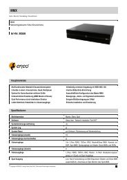
Umrüstkit<br />
EMC 561-MB256 auf EMZ 561-MB256 plus<br />
Art.-Nr. 013230<br />
Lieferumfang<br />
Umrüst-Kit Art.-Nr. 013230 bestehend aus:<br />
- Rechner-/Anschlussplatine 561-MB256 plus<br />
- Adapterblech<br />
- Verbindungskabel 4-polig, Länge 850 mm<br />
- Isolations-Folie<br />
- 5 x Kunststoff-Platinenhalter<br />
- Zylinderschraube M4 x 6 mit Zahnscheibe<br />
- 2 x Programmierstecker<br />
- Adapterplatine für seriellen Drucker<br />
- Programmier-Software "WINFEM Advanced", Art.-Nr. 013498<br />
- Produktbegleitende Dokumentationen zu WINFEM Advanced<br />
sowie zur Zentrale 561-MB256 plus in elektronischer Form<br />
auf der WINFEM Advanced-CD.<br />
Umbau-Vorbereitungen<br />
1.Über WINFEM-Advanced (Art.-Nr. 013498) die aktuelle<br />
Programmierung aus der Zentrale auslesen und abspeichern.<br />
Siehe hierzu Benutzerhandbuch WINFEM Advanced.<br />
2.Einbruchmeldeanlage komplett spannungslos machen<br />
(Netz und Akku).<br />
P00168-28-002-04<br />
2008-08-25<br />
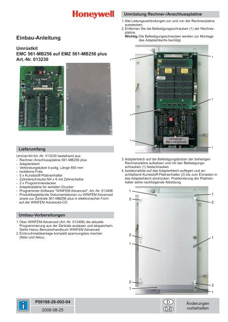
Umrüstung Rechner-/Anschlussplatine<br />
1.Alle Leitungsverbindungen zur und von der Rechnerplatine<br />
ausstecken.<br />
2.Entfernen Sie die Befestigungsschrauben (1) der Rechnerplatine.<br />
Wichtig: Die Befestigungsschrauben werden zur Montage<br />
des Adapterblechs benötigt.<br />
1<br />
1<br />
1<br />
bisherige<br />
Rechnerplatine<br />
3.Adapterblech auf die Befestigungsbolzen der bisherigen<br />
Rechnerplatine aufsetzen und mit den Befestigungsschrauben<br />
(1) festschrauben.<br />
4.Isolationsfolie auf das Adapterblech auflegen und anschließend<br />
Kunststoff-Platinenhalter (2) bis zum Einrasten in<br />
das Adapterblech eindrücken. Positionierung der Platinenhalter<br />
siehe nachfolgende Abbildung.<br />
1<br />
2<br />
2<br />
1<br />
2<br />
1<br />
Änderungen<br />
vorbehalten<br />
1<br />
1<br />
1<br />
1<br />
2<br />
1<br />
2<br />
1
5.Neue Rechner-/Anschlussplatine auf die Kunststoff-Platinenhalter<br />
(2) aufsetzen und bis zum Einrasten aufdrücken.<br />
Wichtig: Platine jeweils direkt beim Platinenhalter nacheinander<br />
eindrücken.<br />
6.Zylinderschraube M4 x 6 inkl. Zahnscheibe (3) einschrauben<br />
und festziehen.<br />
2<br />
2<br />
2<br />
Rechner-/Anschlussplatine<br />
neu<br />
7.Aus beiliegendem Kabel (4-polig) und Federleisten (4-polig)<br />
ein Verbindungskabel zur Spannungsversorgung herstellen.<br />
Neue Rechner-/Anschlussplatine und bisherige Anschlussplatine<br />
mit diesem Versorgungskabel verbinden.<br />
Leitungsverbindungen<br />
Bisherige Anschlussplatine Neue Anschlussplatine<br />
S - FAULT<br />
+12 V - +12 V<br />
0 V - 0 V<br />
N - MAINS<br />
Anschlüsse<br />
Neue Anschlussplatine: Anschlusspins Netzteil (siehe<br />
Grafik "Kurzübersicht der<br />
Anschlüsse")<br />
Bisherige Anschlussplatine:Zweiter Anschluss Netzteil (ST5)<br />
(siehe untenstehende Grafik)<br />
Antenne<br />
Gruppe<br />
Netzteil<br />
8.Restliche Leitungsverbindungen wieder herstellen.<br />
Anschlussbeschreibung siehe nebenstehende Grafik<br />
"Kurzübersicht der Anschlüsse" sowie Installationsanleitung<br />
der Zentrale. Nach Anschluss aller Leitungsverbindungen die<br />
Zentrale wieder in Betrieb nehmen (Netz und Akku).<br />
Ausnahme: Die I-BUS-Verbindung zu den I-BUS-Erweiterungen<br />
erst nach Übertragung der Programmierung mit<br />
WINFEM Advanced wieder herstellen.<br />
Honeywell Security Deutschland<br />
Novar GmbH<br />
Johannes-Mauthe-Straße 14<br />
D-72458 Albstadt<br />
www.honeywell.com/security/de<br />
2<br />
3<br />
2<br />
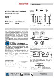
Kurzübersicht der Anschlüsse<br />
e<br />
d<br />
c<br />
a.Stecker für Verbindungskabel zum ersten I-BUS Modul<br />
b.Anschlusspins für Verbindungskabel zum Netz-/Ladeteil<br />
c. Stecker für Anschlusskabel paralleler Drucker<br />
d.D-SUB Stecker für Anschlusskabel serieller Drucker bzw. für<br />
Anschluss DataSafe-Protokollgerät<br />
e.USB-Schnittstelle (Revision 1.1) für<br />
- Download/Upload Applikations-Firmware<br />
- Download/Upload Parametrierung<br />
- Download/Upload Bootloader-Firmware<br />
- Upload Ereignisspeicher<br />
- Upload Alarmspeicher<br />
- Upload FileInfos<br />
Parametrierung<br />
S<br />
+12 V<br />
0 V<br />
N Wichtige Hinweise<br />
P00168-28-002-04<br />
2008-08-25<br />
©2008 Novar GmbH<br />
1.In WINFEM-Advanced (Art.-Nr. 013498) die herunter<br />
geladene Programmierung der Zentrale (bisherige Rechnerplatine)<br />
in neue Zentralenversion konvertieren.<br />
2.Nach der Konvertierung die Programmierung überprüfen und<br />
abspeichern.<br />
3.Geänderte Programmierung in die Zentrale übertragen.<br />
Ausführliche Informationen zur Bedienung von WINFEM<br />
Advanced entnehmen Sie bitte dem Benutzerhandbuch<br />
WINFEM Advanced.<br />
- Mit der "Zentrale" 561-MB256 plus ist kein IGIS-LAN-Betrieb<br />
möglich. Ebenso wird der Anschluss eines seriellen Druckers<br />
über die Adapterplatine Tischdrucker (Art.-Nr. 013220.14) nicht<br />
unterstützt.<br />
- Weitere wichtige Informationen entnehmen Sie bitte der<br />
Installationsanleitung der Zentrale 561-MB256 plus, Kapitel<br />
"Besondere Hinweise zur Installation bzw. Projektierung".<br />
a<br />
b
Mounting Instructions<br />
Retrofit kit<br />
IDC 561-MB256 to IACP 561-MB256 plus<br />
Item no. 013230<br />
Scope of delivery<br />
Retrofit kit item no. 013230 consisting of:<br />
- computer/connection PCB 561-MB256 plus<br />
- adapter plate<br />
- connection cable 4-pole, length 1000 mm<br />
- insulating foil<br />
- 5 x plastic PCB holder<br />
- pan head screw M4 x 6 with tooth lock washer<br />
- 2 x programming plug<br />
- adapter PCB for serial printer<br />
- programming software "WINFEM Advanced", item no. 013498<br />
- accompanying documentation to WINFEM Advanced and<br />
control panel 561-MB256 plus in electronical form on the<br />
WINFEM Advanced CD.<br />
Preparation for retrofitting<br />
1.Download and save the current programming with WINFEM<br />
Advanced (item no. 013498).<br />
For details see user manual WINFEM Advanced.<br />
2.Set the intrusion detection system completely free of voltage<br />
(mains and accumulator).<br />
P00168-28-002-04<br />
2008-08-25<br />
Retrofitting computer/connection PCB<br />
1.Disconnect all cable connections to and from the computer<br />
PCB.<br />
2.Remove the fastening screws (1) of the computer PCB.<br />
Important: The fastening screws are required for mounting<br />
the adapter plate.<br />
1<br />
1<br />
1<br />
current<br />
computer PCB<br />
3.Place the adapter plate on the fastening bolts of the current<br />
computer PCB and screw it down with the fastening screws<br />
(1).<br />
4.Put the insulating foil on the adapter plate and then press the<br />
plastic PCB holders (2) into the adapter plate until they snap<br />
in. Position of the plastic PCB holders you can see in the<br />
following illustration.<br />
1<br />
2<br />
2<br />
1<br />
2<br />
1<br />
Subject to change<br />
without notice<br />
1<br />
1<br />
1<br />
1<br />
2<br />
1<br />
2<br />
1
5.Put the new computer/connection PCB on the plastic PCB<br />
holders (2) and press it on until it snaps in.<br />
Important: Press on the PCB directly at each plastic PCB<br />
holder one after the other.<br />
6.Screw in the pan head screw incl. tooth lock washer (3) and<br />
fasten it.<br />
2<br />
2<br />
2<br />
computer/connection PCB<br />
new<br />
7.Make a connection cable for power supply with the included<br />
cable (4-pole) and socket connectors (4-pole).<br />
Connect the new connection PCB and the current connection<br />
PCB with this connection cable.<br />
Wire connections:<br />
Current connection PCB New connection PCB<br />
S - FAULT<br />
+12 V - +12 V<br />
0 V - 0 V<br />
N - MAINS<br />
Terminals:<br />
New connection PCB: Terminal power supply (see<br />
illustration "Overview of the<br />
terminals")<br />
Current connection PCB: 2nd terminal power supply (ST5)<br />
(see illustration below)<br />
antenna (Antenne)<br />
group (Gruppe)<br />
power supply<br />
(Netzteil)<br />
8.Reconnect the remaining cable connections. For description<br />
of the terminals see illustration "Overview of the terminals"<br />
and Installation Instructions of the central unit.<br />
After connecting all cable connections reactivate the central<br />
unit (mains and accumulator).<br />
Exception: The I-BUS connection to the I-BUS extensions<br />
has to be reestablished not before the programming is transmitted<br />
via WINFEM Advanced.<br />
Honeywell Security Deutschland<br />
Novar GmbH<br />
Johannes-Mauthe-Straße 14<br />
D-72458 Albstadt<br />
www.honeywell.com/security/de<br />
S<br />
+12 V<br />
0 V<br />
N<br />
2<br />
3<br />
2<br />
P00168-28-002-04<br />
2008-08-25<br />
©2008 Novar GmbH<br />
Overview of the terminals<br />
e<br />
d<br />
c<br />
a.Plug for the connection cable to the 1st I-BUS module<br />
b.Terminal for the connection cable to the power supply unit<br />
c. Terminal for the connection cable to a parallel printer<br />
d.D-SUB plug for the connection cable to a serial printer or<br />
a DataSafe prorocol device<br />
e.USB interface (Revision 1.1) for<br />
- Download/Upload applickation firmware<br />
- Download/Upload parameterization<br />
- Download/Upload bootloader firmware<br />
- Upload event memory<br />
- Upload alarm memory<br />
- Upload file infos<br />
Parameterization<br />
1.In WINFEM-Advanced (item no. 013498) convert the downloaded<br />
programming of the central unit (previous computer<br />
PCB) into the new central unit version.<br />
2.After convertion check the programming and save it in<br />
WINFEM Advanced.<br />
3.Upload the changed programming into the control panel.<br />
Exctensive information for operating WINFEM Advanced<br />
you can take from the User Manual WINFEM Advanced.<br />
Important notes<br />
- With the "control panel" 561-MB256 plus no IGIS-LAN<br />
operation is possible. Also, the connection of a serial printer via<br />
the adapter PCB desktop printer (item no. 013220.14) is not<br />
supported.<br />
- For further important information see the Installation Instructions<br />
of the control panel 561-MB256 plus, chapter "Besondere<br />
Hinweise zur Installation bzw. Projektierung".<br />
a<br />
b