

Three-phase Sensorless BLDC Motor Control Kit with the MPC5606B
Three-phase Sensorless BLDC Motor Control Kit with the MPC5606B
Three-phase Sensorless BLDC Motor Control Kit with the MPC5606B

Create successful ePaper yourself
Turn your PDF publications into a flip-book with our unique Google optimized e-Paper software.
Software Implementation<br />
5.2 Application flow<br />
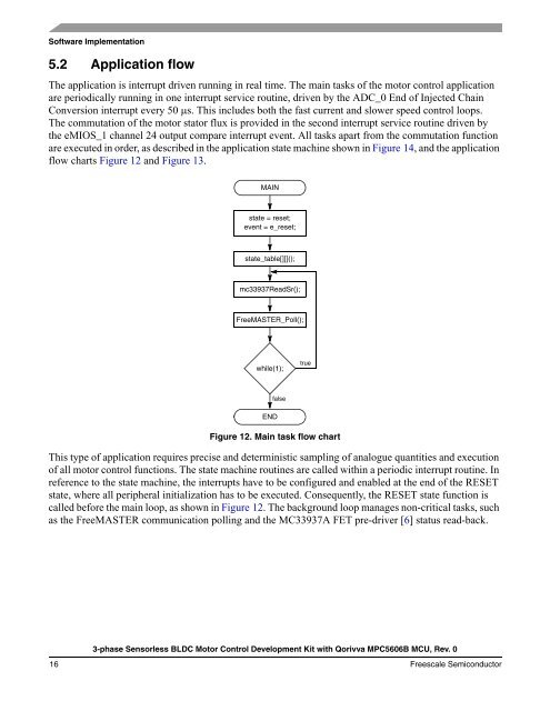
The application is interrupt driven running in real time. The main tasks of <strong>the</strong> motor control application<br />
are periodically running in one interrupt service routine, driven by <strong>the</strong> ADC_0 End of Injected Chain<br />
Conversion interrupt every 50 s. This includes both <strong>the</strong> fast current and slower speed control loops.<br />
The commutation of <strong>the</strong> motor stator flux is provided in <strong>the</strong> second interrupt service routine driven by<br />
<strong>the</strong> eMIOS_1 channel 24 output compare interrupt event. All tasks apart from <strong>the</strong> commutation function<br />
are executed in order, as described in <strong>the</strong> application state machine shown in Figure 14, and <strong>the</strong> application<br />
flow charts Figure 12 and Figure 13.<br />
16<br />
MAIN<br />
state = reset;<br />
event = e_reset;<br />
state_table[][]();<br />
mc33937ReadSr();<br />
FreeMASTER_Poll();<br />
while(1);<br />
END<br />
false<br />
Figure 12. Main task flow chart<br />
This type of application requires precise and deterministic sampling of analogue quantities and execution<br />
of all motor control functions. The state machine routines are called <strong>with</strong>in a periodic interrupt routine. In<br />
reference to <strong>the</strong> state machine, <strong>the</strong> interrupts have to be configured and enabled at <strong>the</strong> end of <strong>the</strong> RESET<br />
state, where all peripheral initialization has to be executed. Consequently, <strong>the</strong> RESET state function is<br />
called before <strong>the</strong> main loop, as shown in Figure 12. The background loop manages non-critical tasks, such<br />
as <strong>the</strong> FreeMASTER communication polling and <strong>the</strong> MC33937A FET pre-driver [6] status read-back.<br />
3-<strong>phase</strong> <strong>Sensorless</strong> <strong>BLDC</strong> <strong>Motor</strong> <strong>Control</strong> Development <strong>Kit</strong> <strong>with</strong> Qorivva <strong>MPC5606B</strong> MCU, Rev. 0<br />
true<br />
Freescale Semiconductor


