Test Fixture Design Presentation - RTP Designers Council
Test Fixture Design Presentation - RTP Designers Council
Test Fixture Design Presentation - RTP Designers Council

Create successful ePaper yourself
Turn your PDF publications into a flip-book with our unique Google optimized e-Paper software.
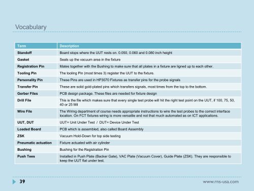
Vocabulary<br />
Term Description<br />
Standoff Board stops where the UUT rests on. 0.050, 0.060 and 0.080 inch height<br />
Gasket Seals up the vacuum area in the fixture<br />
Registration Pin Mates together with the Bushing to make sure that all plates in a fixture are ligned up to each other.<br />
Tooling Pin The tooling Pin (most times 3) register the UUT to the fixture.<br />
Personality Pin These Pins are used in HP3070 <strong>Fixture</strong>s as transfer pins for the probe signals<br />
Transfer Pin These are solid gold-plated pins which transfers signals, most times from the top to the bottom.<br />
Gerber Files PCB design package. These files are needed for fixture design<br />
Drill File This is the file which makes sure that every single test probe will hit the right test point on the UUT, if 100, 75, 50,<br />
40 or 25 Mil<br />
Wire File The Wiring department of course needs appropriate instructions to wire the test probes to the correct interface<br />
location. On FCT fixtures wiring is more versatile and not that much automated as on ICT applications.<br />
UUT, DUT UUT= Unit Under <strong>Test</strong> / DUT= Device Under <strong>Test</strong><br />
Loaded Board PCB which is assembled, also called Board Assembly<br />
ZSK Vacuum Hold-Down for top side testing<br />
Pneumatic actuation <strong>Fixture</strong> actuated with air cylinder<br />
Bushing Bushing for the Registration Pin<br />
Push Tees Installed in Push Plate (Backer Gate), VAC Plate (Vacuum Cover), Guide Plate (ZSK). They are responsible to<br />
keep the UUT flat under test.<br />
39 www.rns-usa.com