VICTRIX Superior kW Export VICTRIX Superior kW X ... - Immergas
VICTRIX Superior kW Export VICTRIX Superior kW X ... - Immergas
VICTRIX Superior kW Export VICTRIX Superior kW X ... - Immergas

You also want an ePaper? Increase the reach of your titles
YUMPU automatically turns print PDFs into web optimized ePapers that Google loves.
1 <strong>VICTRIX</strong> <strong>Superior</strong> <strong>kW</strong> FEATURES<br />
Condensing type wall-hung sealed chamber fan assisted premix boiler for<br />
heating and production of domestic hot water with maximum useful heat<br />
output of 32 <strong>kW</strong> (27,520 kcal/h) with high efficiency and forced circulation.<br />
By varying the type of installation the boiler classification also varies.<br />
OUTDOOR INSTALLATION (in a partially protected place): Appliance<br />
type C with direct air intake- if installed using a flue terminal and the<br />
(optional) mandatory upper cover kit, also eliminating a sealed chamber<br />
intake cap.<br />
Appliance type C 13 / C 33 / C 83 - if installed using the vertical or horizontal concentric<br />
kits (cover kit recommended but not mandatory) or the Ø 80/80 separator kit<br />
without using the upper cover kit.<br />
INDOOR INSTALLATION:<br />
Appliance type C 13 / C 33 / C 43 / C 53 / C 83 - if installed using the vertical or horizontal<br />
concentric kits or the Ø 80/80 separator kit.<br />
Appliance type B 23 - if installed using a flue kit and the (optional) mandatory<br />
upper cover kit, also eliminating a sealed chamber intake cap.<br />
The boiler comprises:<br />
• total premix combustion system with steel cylindrical multigas burner,<br />
complete with ignition electrode and ionisation control electrode;<br />
• pneumatic gas valve with double shutter;<br />
• primary gas/water heat exchanger with stainless steel coil;<br />
• stainless steel combustion chamber insulated internally using ceramic<br />
panels;<br />
• fan for the evacuation of fumes at an electronically variable speed;<br />
• circuit for the elimination of condensate including siphon and flexible drain<br />
pipe;<br />
• 22 stainless steel plate secondary water/water heat exchanger for the<br />
production of domestic hot water;<br />
• "Aqua Celeris" system made up from one mini storage tank inserted into<br />
the primary circuit and kept at temperature by a modulating electrical<br />
resistance;<br />
• hydraulic unit comprising a 3-way electric valve, an adjustable-speed<br />
circulating pump with built-in air separator, adjustable by-pass, absolute<br />
pressure switch for the primary circuit, 3 bar safety valve for the primary<br />
circuit, a system draining fitting and filling valve;<br />
• domestic hot water flow rate adjuster including domestic hot water inlet<br />
probe and domestic hot water flow meter to check circulating flow rate;<br />
• 7.5 litre expansion vessel system with diaphragm (real 6.8) with pre-load<br />
at 1.0 bar and manometer;<br />
• water overheating safety thermostat and fumes overheating thermostat;<br />
• control panel with Stand-by/On button, functioning mode button<br />
1<br />
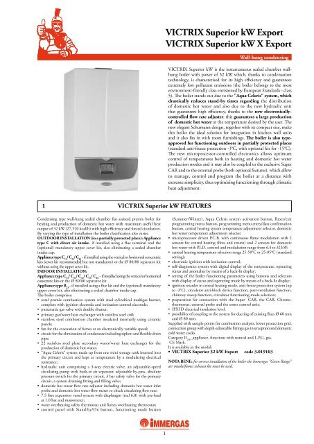
<strong>VICTRIX</strong> <strong>Superior</strong> <strong>kW</strong> <strong>Export</strong><br />
<strong>VICTRIX</strong> <strong>Superior</strong> <strong>kW</strong> X <strong>Export</strong><br />
Wall-hung condensing<br />
<strong>VICTRIX</strong> <strong>Superior</strong> <strong>kW</strong> is the instantaneous sealed chamber wallhung<br />
boiler with power of 32 <strong>kW</strong> which, thanks to condensation<br />
technology, is characterised for its high efficiency and guarantees<br />
extremely low pollutant emissions (the boiler belongs to the most<br />
environment-friendly class envisioned by European Standards - class<br />
5). The boiler stands out due to the "Aqua Celeris" system, which<br />
drastically reduces stand-by times regarding the distribution<br />
of domestic hot water and also due to the new hydraulic unit<br />
that guarantees high efficiency, thanks to the new electronicallycontrolled<br />
flow rate adjuster: this guarantees a large production<br />
of domestic hot water at the temperature desired by the user. The<br />
new elegant Schumann design, together with its compact size, make<br />
this boiler the ideal solution for integration in kitchen wall units<br />
and it also fits in with room furnishings. The boiler is also typeapproved<br />
for functioning outdoors in partially protected places<br />
(standard anti-freeze protection -3°C, with optional kit for -15°C).<br />
The new microprocessor-controlled electronics allows optimum<br />
control of temperatures both in heating and domestic hot water<br />
production modes and it may also be coupled to the exclusive Super<br />
CAR and to the external probe (both optional features), which allow<br />
to manage, control and program the boiler at a distance with<br />
extreme simplicity, thus optimising functioning through climatic<br />
heat adjustment.<br />
(Summer/Winter), Aqua Celeris system activation button, Reset/exit<br />
programming menu button, programming menu entry/data confirmation<br />
button, central heating system temperature adjustment selector, domestic<br />
hot water temperature adjustment selector.<br />
• microprocessor driven P.C.B. with continuous flame modulation with 2<br />
sensors for central heating (flow and return) and 2 sensors for domestic<br />
hot water with P.I.D. control and modulation range from 6.4 to 32 <strong>kW</strong>:<br />
• central heating temperature selection range 25-50°C or 25-85°C (standard<br />
setting);<br />
• electronic ignition with ionisation control;<br />
• self-diagnostics system with digital display of the temperature, operating<br />
status and anomalies by means of a back-lit display;<br />
• setting of the boiler functioning parameters using buttons and selectors<br />
with display of status and operating mode by means of a back-lit display;<br />
• ignition retarder in central heating mode, anti-freeze protection system (up<br />
to -3°C), circulator anti-block device function, post-ventilation function,<br />
chimney sweep function, circulator functioning mode selection;<br />
• preparation for connection with the Super CAR, the CAR, Chronothermostat,<br />
external probe and the zones control unit;<br />
• IPX5D electrical insulation level.<br />
• possibility of coupling to the system for ducting of existing flues Ø 60 mm<br />
and Ø 80 mm.<br />
Supplied with sample points for combustion analysis, lower protection grid,<br />
connection group with depth-adjustable fittings gas interception and domestic<br />
cold water cocks.<br />
Category II 2H3+ appliance, functions with natural and L.P.G. gas.<br />
CE Mark.<br />
It is available in the model:<br />
• <strong>VICTRIX</strong> <strong>Superior</strong> 32 <strong>kW</strong> <strong>Export</strong> code 3.019103<br />
NOTA BENE: for correct installation of the boiler the <strong>Immergas</strong> "Green Range"<br />
air intake/fumes exhaust kit must be used.
2 <strong>VICTRIX</strong> <strong>Superior</strong> 32 <strong>kW</strong> X FEATURES<br />
Condensing type wall-hung sealed chamber fan assisted premix boiler<br />
for central heating with maximum useful heat output of 32 <strong>kW</strong><br />
(27.520 kcal/h) with high efficiency and forced circulation. Thanks<br />
to a particular kit (optional) it can be coupled to a separate 80, 105,<br />
120 and 200 litre Storage Tank Unit for the production of domestic<br />
hot water. By varying the type of installation the boiler classification<br />
also varies.<br />
OUTDOOR INSTALLATION (in a partially protected place):<br />
Appliance type C with direct air intake - if installed using a flue<br />
terminal and the (optional) mandatory upper cover kit, also eliminating<br />
a sealed chamber intake cap.<br />
Appliance type C 13 / C 33 / C 83 -if installed using the vertical or horizontal<br />
concentric kits (cover kit recommended but not mandatory) or the Ø<br />
80/80 separator kit without using the upper cover kit.<br />
INDOOR INSTALLATION:<br />
Appliance type C 13 / C 33 / C 43 / C 53 / C 83 - if installed using the vertical<br />
or horizontal concentric kits or the Ø 80/80 separator kit.<br />
Appliance type B 23 - if installed using a flue kit and the (optional)<br />
mandatory upper cover kit, also eliminating a sealed chamber intake<br />
cap.<br />
The boiler comprises:<br />
• total premix combustion system with steel cylindrical multigas<br />
burner, complete with ignition electrode and ionisation control<br />
electrode;<br />
• pneumatic gas valve with double shutter;<br />
• primary gas/water heat exchanger with stainless steel coil;<br />
• stainless steel combustion chamber insulated internally using<br />
ceramic panels;<br />
• fan for the evacuation of fumes at an electronically variable<br />
speed;<br />
• circuit for the elimination of condensate including siphon and<br />
flexible drain pipe;<br />
• hydraulic unit comprising an adjustable-speed circulating pump<br />
with built-in air separator, adjustable by-pass, , absolute pressure<br />
switch for the primary circuit, 3 bar safety valve for the primary<br />
circuit, a system draining fitting , ball valve for system filling;<br />
• 8.0 litre expansion vessel system with diaphragm (real 8.0) with<br />
pre-load at 1.0 bar and manometer<br />
• water overheating safety thermostat and fumes overheating<br />
thermostat;<br />
• control panel with Stand-by/On button, functioning mode button<br />
(Summer/Winter), domestic hot water priory temporary inhibition<br />
2<br />
<strong>VICTRIX</strong> <strong>Superior</strong> <strong>kW</strong> <strong>Export</strong><br />
<strong>VICTRIX</strong> <strong>Superior</strong> <strong>kW</strong> X <strong>Export</strong><br />
<strong>VICTRIX</strong> <strong>Superior</strong> <strong>kW</strong> X is the wall-hung condensing boiler for<br />
room central heating only with 32 <strong>kW</strong> power which, thanks to<br />
condensation technology is distinguished for its particularly high<br />
efficiency. The innovative total premix combustion system and the<br />
special environment-friendly burner mean it can run on natural<br />
or LPG gas, guaranteeing extremely low pollutant emissions (the<br />
boiler belongs to the most environment-friendly class envisioned by<br />
European Standards - class 5). Thanks to a particular kit (optional)<br />
the boiler can be connected to a separate <strong>Immergas</strong> 80, 105, 120 or<br />
200 litre Storage Tank Unit, which guarantees a large production<br />
of domestic hot water. This is especially ideal for homes with more<br />
than one bathroom and where great amounts of water are required<br />
quickly. The boiler is type-approved also for functioning outdoors<br />
in partially protected places (standard anti-freeze protection -3°C,<br />
with optional kit for -15°C). The new microprocessor controlled<br />
electronics allows optimum control of temperatures both in central<br />
heating and domestic hot water production modes (if the optional<br />
storage tank unit kit is installed) and it may also be coupled to<br />
the exclusive Super CAR and to the external probe (both optional<br />
features), which allow to manage, control and program the boiler<br />
at a distance with extreme simplicity, thus optimising functioning<br />
through climatic heat adjustment.<br />
button (if the Storage Tank Unit coupling kit is used), Reset/exit<br />
programming menu button, programming menu entry/data confirmation<br />
button, central heating system temperature adjustment<br />
selector, domestic hot water temperature adjustment selector (if the<br />
Storage Tank Unit coupling kit is used).<br />
• microprocessor driven P.C.B. with continuous flame modulation<br />
with 2 sensors for central heating (flow and return) with P.I.D.<br />
control and modulation range from 6.4 to 32 <strong>kW</strong>:<br />
• central heating temperature selection range 25-50°C or 25-85°C<br />
(standard setting);<br />
• electronic ignition with ionisation control;<br />
• self-diagnostics system with digital display of the operating status<br />
and anomalies by means of a back-lit display;<br />
• setting of the boiler functioning parameters using buttons and<br />
selectors with display of status and operating mode by means of a<br />
back-lit display;<br />
• ignition retarder in central heating mode, anti-freeze protection<br />
system (up to -3°C), circulator anti-block device function, postventilation<br />
function, chimney sweep function, circulator functioning<br />
mode selection;<br />
• preparation for connection with the Super CAR, the CAR, chronothermostat,<br />
external probe and the zones control unit;<br />
• IPX5D electrical insulation level.<br />
• possibility of coupling to the system for ducting of existing flues Ø<br />
60 mm and Ø 80 mm.<br />
Supplied with sample points for combustion analysis, lower protection<br />
grid, connection group with depth-adjustable fittings and gas<br />
interception cock.<br />
Category II 2H3+ appliance, functions with natural and L.P.G. gas.<br />
CE Mark.<br />
It is available in the model:<br />
• <strong>VICTRIX</strong> <strong>Superior</strong> 32 <strong>kW</strong> X <strong>Export</strong> code 3.019104<br />
NOTA BENE: for correct installation of the boiler the <strong>Immergas</strong> "Green<br />
Range" air intake/fumes exhaust kit must be used.
3 <strong>VICTRIX</strong> <strong>Superior</strong> <strong>kW</strong> MAIN COMPONENTS<br />
KEY:<br />
1 - D.H.W. flow rate regulator<br />
2 - Condensate drain tap<br />
3 - D.H.W. probe<br />
4 - D.H.W. flow meter<br />
5 - Fan<br />
6 - Gas nozzle<br />
7 - Gas valve<br />
8 - Venturi<br />
9 - Detection electrode<br />
10 - Flue safety thermostat<br />
11 - Air intake pipe<br />
12 - Condensation module<br />
13 - Negative signal pressure point<br />
14 - Positive signal pressure point<br />
15 - Sample points (air A) - (fumes F)<br />
<strong>VICTRIX</strong> <strong>Superior</strong> <strong>kW</strong> <strong>Export</strong><br />
<strong>VICTRIX</strong> <strong>Superior</strong> <strong>kW</strong> X <strong>Export</strong><br />
3<br />
16 - Manual vent valve<br />
17 - Burner<br />
18 - Ignition electrode<br />
19 - Flow probe<br />
20 - Safety thermostat<br />
21 - Aqua Celeris<br />
22 - Automatic vent valve<br />
23 - System expansion vessel<br />
24 - Return probe<br />
25 - Boiler pump<br />
26 - System pressure switch<br />
27 - D.H.W. heat exchanger<br />
28 - 3 bar safety valve<br />
29 - 3-way valve (motorised)<br />
30 - System draining valve<br />
31 - D.H.W. inlet probe<br />
32 - System filling valve
4<br />
<strong>VICTRIX</strong> <strong>Superior</strong> <strong>kW</strong> <strong>Export</strong><br />
<strong>VICTRIX</strong> <strong>Superior</strong> <strong>kW</strong> X <strong>Export</strong><br />
4 <strong>VICTRIX</strong> <strong>Superior</strong> <strong>kW</strong> X MAIN COMPONENTS<br />
KEY:<br />
1 - Condensate drain tap<br />
2 - Fan<br />
3 - Gas nozzle<br />
4 - Gas valve<br />
5 - Venturi<br />
6 - Detection electrode<br />
7 - Flue safety thermostat<br />
8 - Air intake pipe<br />
9 - Condensation module<br />
10 - Negative signal pressure point<br />
11 - Positive signal pressure point<br />
12 - Sample points (air A) - (fumes F<br />
13 - Manual vent valve<br />
14 - Burner<br />
15 - Ignition electrode<br />
16 - Flow probe<br />
17 - Safety thermostat<br />
18 - Automatic vent valve<br />
19 - System expansion vessel<br />
20 - Return probe<br />
21 - Boiler pump<br />
22 - System pressure switch<br />
23 - 3 bar safety valve<br />
24 - System draining valve<br />
25 - System filling valve
5 <strong>VICTRIX</strong> <strong>Superior</strong> <strong>kW</strong> MAIN DIMENSIONS<br />
Model<br />
<strong>VICTRIX</strong> <strong>Superior</strong> <strong>kW</strong><br />
5.1 CONNECTIONS<br />
Model<br />
B<br />
<strong>VICTRIX</strong> <strong>Superior</strong> <strong>kW</strong><br />
Height mm<br />
830<br />
Flow<br />
M<br />
3/4"<br />
A B<br />
Return<br />
R<br />
3/4"<br />
Width mm<br />
440<br />
<strong>VICTRIX</strong> <strong>Superior</strong> <strong>kW</strong> <strong>Export</strong><br />
<strong>VICTRIX</strong> <strong>Superior</strong> <strong>kW</strong> X <strong>Export</strong><br />
Hot Outlet<br />
AC<br />
1/2"<br />
5<br />
Depth mm<br />
350<br />
A = intake/exhaust<br />
B = intake<br />
Cold Inlet<br />
AF<br />
1/2"<br />
Gas<br />
G<br />
3/4"<br />
Ø int./exhaust mm<br />
100/60<br />
Distance between the casing upper line and<br />
concentric bend axis Ø 60/100: 95 mm<br />
Casing upper line<br />
Distance between the casing upper line and separator bend<br />
axis Ø 80/80: A = 135 mm; B = 115 mm<br />
Expansion Vessel<br />
Litres<br />
7.5 (real 6.8)
6 <strong>VICTRIX</strong> <strong>Superior</strong> <strong>kW</strong> X MAIN DIMENSIONS<br />
Model<br />
<strong>VICTRIX</strong> <strong>Superior</strong> <strong>kW</strong> X<br />
6.1 CONNECTIONS<br />
B<br />
Height mm<br />
830<br />
A B<br />
* Only in the presence of the Storage Tank Unit coupling<br />
kit<br />
Model<br />
<strong>VICTRIX</strong> Super <strong>kW</strong> X<br />
Flow<br />
M<br />
3/4"<br />
Return<br />
R<br />
3/4"<br />
6<br />
<strong>VICTRIX</strong> <strong>Superior</strong> <strong>kW</strong> <strong>Export</strong><br />
<strong>VICTRIX</strong> <strong>Superior</strong> <strong>kW</strong> X <strong>Export</strong><br />
Width mm<br />
440<br />
* Stor. tank<br />
Flow MU<br />
3/4"<br />
A = intake/exhaust<br />
B = intake<br />
Depth mm<br />
350<br />
Distance between the casing upper line and<br />
concentric bend axis Ø 60/100: 95 mm<br />
Ø int./exhaust mm<br />
100/60<br />
Distance between the casing upper line and separator<br />
bend axis Ø 80/80: A = 135 mm; B = 115 mm<br />
* Stor.ank<br />
Ret. RU<br />
3/4"<br />
System Filling<br />
RR<br />
1/2"<br />
Casing upper line<br />
Gas<br />
G<br />
3/4"<br />
Expansion Vessel<br />
Litres<br />
8 (real 8.0)
<strong>VICTRIX</strong> <strong>Superior</strong> <strong>kW</strong> <strong>Export</strong><br />
<strong>VICTRIX</strong> <strong>Superior</strong> <strong>kW</strong> X <strong>Export</strong><br />
7 STORAGE TANK UNIT MAIN DIMENSIONS (Optional)<br />
Stor. tank Flow<br />
MU<br />
80 l storage tank unit 105 l storage tank unit 120 l storage tank unit 200 l storage tank unit<br />
Height mm 850 1020 850 1250<br />
Width mm 500 500 600 600<br />
Depth mm 500 500 600 600<br />
Stor. tank Ret.<br />
RU<br />
80 litre storage tank unit<br />
120 litre storage tank unit<br />
Cold Inlet<br />
AF<br />
Hot Outlet<br />
AC<br />
7<br />
Recirc.<br />
RC<br />
105 litre storage tank unit<br />
Panels Flow<br />
MP (op S.T.U. 200)<br />
200 litre storage tank unit<br />
3/4” 3/4” 1/2” 1/2” 1/2” 3/4” 3/4”<br />
Panels Flow<br />
RP (op. S.T.U. 200)
8 PUMP HEAD/FLOW RATE GRAPHICS<br />
The "<strong>VICTRIX</strong> <strong>Superior</strong> <strong>kW</strong> / <strong>kW</strong> X” series boilers are<br />
supplied with pump incorporated with electric three-speed<br />
adjuster plus automatic speed (factory-set). The automatic<br />
speed decides the most suitable setting for the pump on the<br />
basis of the ∆T measured between system flow and return.<br />
The pump is already equipped with a condenser.<br />
8.1 <strong>VICTRIX</strong> <strong>Superior</strong> 32 <strong>kW</strong> - 32 <strong>kW</strong> X PUMP<br />
Head (kPa)<br />
D<br />
F<br />
C<br />
GRUNDFOS UPRO 15-70 AO HB<br />
A<br />
E<br />
8<br />
<strong>VICTRIX</strong> <strong>Superior</strong> <strong>kW</strong> <strong>Export</strong><br />
<strong>VICTRIX</strong> <strong>Superior</strong> <strong>kW</strong> X <strong>Export</strong><br />
The "<strong>VICTRIX</strong> <strong>Superior</strong> <strong>kW</strong> / <strong>kW</strong> X" series boilers have an<br />
adjustable by-pass that is set in the factory (screw turned by 1.5<br />
turns with respect to the adjustment screw that is completely<br />
unscrewed).<br />
The adjustment can be modified by acting on the screw located<br />
on the by-pass unit.<br />
Flow rate l/h<br />
A: Head available to the system at third speed with by-pass excluded (adjustment screw tightened fully home).<br />
B: Head available to the system at second speed with by-pass excluded (adjustment screw tightened fully home).<br />
C: Head available to the system at first speed with by-pass excluded (adjustment screw tightened fully home).<br />
D: Head available to the system at third speed (screw tightened by 1.5 turns with respect to the adjustment screw that<br />
is completely unscrewed).<br />
E: Head available to the system at second speed (screw tightened by 1.5 turns with respect to the adjustment screw that<br />
is completely unscrewed).<br />
F: Head available to the system at first speed (screw tightened by 1.5 turns with respect to the adjustment screw that is<br />
completely unscrewed).<br />
B<br />
Head (m H 2 O)
9 <strong>VICTRIX</strong> <strong>Superior</strong> <strong>kW</strong> WIRING DIAGRAM<br />
ROOM THERMOSTAT OR REMOTE CONTROL<br />
The Comando Amico Remoto (CAR) remote control or<br />
the Super Comando Amico Remoto remote control, must<br />
be connected to terminals 42 and 43 of the connector X15<br />
on the integrated P.C.B. respecting polarity and eliminating<br />
Brown<br />
Blue<br />
Blue<br />
Blue<br />
Power Supply<br />
230 Vac 50 Hz<br />
Brown<br />
Brown<br />
White<br />
Violet<br />
Black<br />
Blue<br />
Super CAR<br />
(optional)<br />
Brown<br />
Black<br />
D.H.W.<br />
White<br />
ZONE CONTROL<br />
UNIT(optional)<br />
Red (C.H.)<br />
Black<br />
Black<br />
White<br />
White<br />
Blue<br />
Brown<br />
IMG BUS<br />
link<br />
FAN SPEED<br />
<strong>VICTRIX</strong> <strong>Superior</strong> <strong>kW</strong> <strong>Export</strong><br />
<strong>VICTRIX</strong> <strong>Superior</strong> <strong>kW</strong> X <strong>Export</strong><br />
KEY:<br />
A4 - Display board<br />
E11 - Aqua Celeris resistance<br />
B1 - Flow probe<br />
F1 - Line fuse<br />
B2 - D.H.W. probe<br />
G2 - Igniter<br />
B4 - External probe (optional)<br />
M1 - Boiler pump<br />
B5 - Return probe<br />
M20 - Fan<br />
B6 - D.H.W. flow meter<br />
M30 - 3-way valve<br />
B9 - D.H.W. inlet probe<br />
M40 - D.H.W. flow rate regulator<br />
CAR - Comando Amico Remoto remote control S5 - System pressure switch<br />
(optional)<br />
S20 - Room thermostat (optional)<br />
E1 - Ignition electrode<br />
Super CAR - SUPER Comando Amico Remoto<br />
E2 - Detection electrode<br />
remote control (optional)<br />
E4 - Safety thermostat<br />
T1 - Voltage transformer<br />
E6 - Flue safety thermostat<br />
X40 - Room thermostat jumper<br />
Y1 - Gas valve<br />
9<br />
jumper X40.<br />
The boiler is designed to use the Room Thermostat (S20).<br />
Connect the room thermostat to terminals 40 and 41 of the<br />
connector X15 eliminating jumper X40.<br />
Any external probe (B4) must be connected to terminals 38<br />
and 39 of the connector X15 on the integrated P.C.B.<br />
White<br />
Black<br />
Orange<br />
Rose<br />
Rose<br />
Red<br />
Yellow<br />
Green<br />
Blue<br />
Black<br />
Green<br />
Black<br />
Black<br />
Blue<br />
Blue<br />
White<br />
White<br />
Grey<br />
Grey<br />
Rose<br />
Orange<br />
White<br />
Black<br />
Red
10 <strong>VICTRIX</strong> <strong>Superior</strong> <strong>kW</strong> X WIRING DIAGRAM<br />
ROOM THERMOSTAT OR REMOTE CONTROL<br />
The Comando Amico Remoto (CAR) remote control or<br />
the Super Comando Amico Remoto remote control, must<br />
be connected to terminals 42 and 43 of the connector X15<br />
on the integrated P.C.B. respecting polarity and eliminating<br />
Brown<br />
Blue<br />
Blue<br />
Brown<br />
White<br />
Violet<br />
Black<br />
STORAGE<br />
TANK<br />
(optional)<br />
Blue<br />
Brown<br />
Black<br />
Power Supply<br />
230 Vac 50 Hz<br />
(D.H.W.)<br />
White<br />
Red (C.H.)<br />
White<br />
White<br />
Super CAR<br />
(optional)<br />
10<br />
<strong>VICTRIX</strong> <strong>Superior</strong> <strong>kW</strong> <strong>Export</strong><br />
<strong>VICTRIX</strong> <strong>Superior</strong> <strong>kW</strong> X <strong>Export</strong><br />
jumper X40.<br />
The boiler is designed to use the Room Thermostat (S20).<br />
Connect the room thermostat to terminals 40 and 41 of the<br />
connector X15 eliminating jumper X40.<br />
Any external probe (B4) must be connected to terminals 38<br />
and 39 of the connector X15 on the integrated P.C.B.<br />
KEY:<br />
A4 - Display board<br />
G2 - Igniter<br />
B1 - Flow probe<br />
M1 - Boiler pump<br />
B2 - D.H.W. probe (optional)<br />
M20 - Fan<br />
B4 - External probe (optional)<br />
M30 - 3-way valve (optional)<br />
B5 - Return probe<br />
R8 - Storage tank inibitor resistor<br />
CAR - Comando Amico Remoto remote control S5 - System pressure switch<br />
(optional)<br />
S20 - Room thermostat (optional)<br />
E1 - Ignition electrode<br />
Super CAR - SUPER Comando Amico Remoto<br />
E2 - Detection electrode<br />
remote control (optional)<br />
E4 - Safety thermostat<br />
T1 - Voltage transformer<br />
E6 - Flue safety thermostat<br />
X40 - Room thermostat jumper<br />
F1 - Line fuse<br />
Y1 - Gas valve<br />
Black<br />
Black<br />
Blue<br />
Blue<br />
White<br />
ZONE CONTROL<br />
UNIT(optional)<br />
White<br />
Grey<br />
Grey<br />
IMG BUS<br />
link<br />
Black<br />
Black<br />
White<br />
White<br />
Blue<br />
Brown<br />
FAN SPEED<br />
Storage Tank<br />
function jumper<br />
Blue<br />
Rose<br />
Orange<br />
White<br />
Black<br />
Red
<strong>VICTRIX</strong> <strong>Superior</strong> <strong>kW</strong> <strong>Export</strong><br />
<strong>VICTRIX</strong> <strong>Superior</strong> <strong>kW</strong> X <strong>Export</strong><br />
11 <strong>VICTRIX</strong> <strong>Superior</strong> <strong>kW</strong> HYDRAULIC LAY-OUT<br />
Attention: check the presence and cleanliness of the water inlet<br />
filter (2), which guarantees boiler efficiency.<br />
11<br />
KEY:<br />
1 - Condensate drain tap<br />
2 - Water inlet filter<br />
3 - D.H.W. flow rate regulator<br />
4 - D.H.W. probe<br />
5 - D.H.W. flow meter<br />
6 - D.H.W. heat exchanger<br />
7 - Aqua Celeris resistance<br />
8 - Gas valve<br />
9 - Gas valve outlet pressure point (P3)<br />
10 - Aqua Celeris<br />
11 - Air/gas Venturi collector<br />
12 - Fan<br />
13 - Gas nozzle<br />
14 - Detection electrode<br />
15 - Flue safety thermostat<br />
16 - Air intake pipe<br />
17 - Condensation module<br />
18 - Manual vent valve<br />
19 - Fumes hood<br />
20 - Air sample point<br />
21 - ∆p gas pressure point<br />
22 - Flue sample point<br />
23 - Flow probe<br />
24 - Safety thermostat<br />
25 - Burner<br />
26 - Ignition electrode<br />
27 - Condensation module cover<br />
28 - Venturi negative signal (P2)<br />
29 - Venturi positive signal (P1)<br />
30 - Return probe<br />
31 - System expansion vessel<br />
32 - Air vent valve<br />
33 - Boiler pump<br />
34 - One-way valve<br />
35 - 3-way valve (motorised)<br />
36 - System draining valve<br />
37 - System filling valve<br />
38 - Adjustable by-pass<br />
39 - System pressure switch<br />
40 - 3 bar safety valve<br />
41 - D.H.W. inlet probe
12<br />
<strong>VICTRIX</strong> <strong>Superior</strong> <strong>kW</strong> <strong>Export</strong><br />
<strong>VICTRIX</strong> <strong>Superior</strong> <strong>kW</strong> X <strong>Export</strong><br />
12 <strong>VICTRIX</strong> <strong>Superior</strong> <strong>kW</strong> X HYDRAULIC LAY-OUT<br />
KEY:<br />
1 - Condensate drain tap<br />
2 - System filling valve<br />
3 - Gas valve<br />
4 - Gas valve outlet pressure point (P3)<br />
5 - Air/gas Venturi collector<br />
6 - Fan<br />
7 - Gas nozzle<br />
8 - Detection electrode<br />
9 - Flue safety thermostat<br />
10 - Air intake pipe<br />
11 - Condensation module<br />
12 - Manual vent valve<br />
13 - Fumes hood<br />
14 - Air sample point<br />
15 - ∆p gas pressure point<br />
16 - Flue sample point<br />
17 - Flow probe<br />
18 - Safety thermostat<br />
19 - Burner<br />
20 - Ignition electrode<br />
21 - Condensation module cover<br />
22 - Venturi negative signal (P2)<br />
23 - Venturi positive signal (P1)<br />
24 - Return probe<br />
25 - System expansion vessel<br />
26 - Air vent valve<br />
27 - Boiler pump<br />
28 - System draining valve<br />
29 - System pressure switch<br />
30 - Adjustable by-pass<br />
31 - 3 bar safety valve<br />
32 - One-way valve (Europa)
13 <strong>VICTRIX</strong> <strong>Superior</strong> 32 <strong>kW</strong> TECHNICAL DATA<br />
<strong>VICTRIX</strong> <strong>Superior</strong> <strong>kW</strong> <strong>Export</strong><br />
<strong>VICTRIX</strong> <strong>Superior</strong> <strong>kW</strong> X <strong>Export</strong><br />
Maximum nominal heat input <strong>kW</strong> (kcal/h) 32.7 (28,082)<br />
Maximum useful/nominal heat output <strong>kW</strong> (kcal/h) 32.0 (27,520)<br />
Minimum nominal heat input <strong>kW</strong> (kcal/h) 6.6 (5,634)<br />
Minimum useful/nominal heat output <strong>kW</strong> (kcal/h) 6.4 (5,504)<br />
Efficiency at 100% Pn (80/60°C) % 98.0<br />
Efficiency at 30% of the load (80/60°C) % 100.6<br />
Efficiency at 100% Pn (50/30°C) % 104.7<br />
Efficiency at 30% of the load (50/30°C) % 106.8<br />
Efficiency at 100% Pn (40/30°C) % 105.7<br />
Efficiency at 30% of the load (40/30°C) % 107.0<br />
Central heating system<br />
Central heating adjustable temperature (range 1 / range 2) °C 25 - 85 / 25 - 50<br />
Max. system operating temperature °C 90<br />
Max. system operating pressure bar 3<br />
System expansion vessel nominal/real capacity litres 7.5 / (6.8)<br />
System expansion vessel pre-load pressure bar 1.0<br />
Head available with flow rate of 1000 l/h kPa (m H 2 O) 26.48 (2.70)<br />
Domestic Hot Water Circuit<br />
Hot water production useful heat output <strong>kW</strong> (kcal/h) 32.0 (27,520)<br />
D.H.W. temperature adjustment °C 30 - 60<br />
D.H.W. circuit minimum dynamic pressure bar 0.3<br />
D.H.W. circuit maximum pressure bar 10<br />
D.H.W. min. flow rate litres/min 1.5<br />
Flow rate for continuous service (∆t 30°C) litres/min 16.3<br />
Gas supply<br />
Gas pressure at the METHANE burner (G20) MIN - MAX mbar 0.14 - 2.45<br />
Gas pressure at the LPG burner (G30) MIN - MAX mbar 0.15 - 2.68<br />
Gas pressure at the LPG burner (G31) MIN - MAX mbar 0.18 - 3.35<br />
Gas pressure at the METHANE burner (G20) MIN - MAX m 3 /h 0.70 - 3.46<br />
Gas pressure at the LPG burner (G30) MIN - MAX kg/h 0.52 - 2.58<br />
Gas pressure at the LPG burner (G31) MIN - MAX kg/h 0.51 - 2.54<br />
Supply voltage V/Hz 230 - 50<br />
Nominal power absorption A 0.62<br />
Installed electric power W 135<br />
Power absorbed by the fan W 26<br />
Power absorbed by the pump W 95<br />
Electrical insulation degree IP X5D<br />
Boiler water content (Aqua Celeris) litres 7.8 (4.0)<br />
Empty boiler weight kg 53.5<br />
13
14<br />
<strong>VICTRIX</strong> <strong>Superior</strong> <strong>kW</strong> <strong>Export</strong><br />
<strong>VICTRIX</strong> <strong>Superior</strong> <strong>kW</strong> X <strong>Export</strong><br />
13.1 <strong>VICTRIX</strong> <strong>Superior</strong> 32 <strong>kW</strong> X TECHNICAL DATA<br />
Maximum nominal heat input <strong>kW</strong> (kcal/h) 32.7 (28,082)<br />
Maximum useful/nominal heat output <strong>kW</strong> (kcal/h) 32.0 (27,520)<br />
Minimum nominal heat input <strong>kW</strong> (kcal/h) 6.6 (5,674)<br />
Minimum useful/nominal heat outputa <strong>kW</strong> (kcal/h) 6.4 (5,504)<br />
Efficiency at 100% Pn (80/60°C) % 98.0<br />
Efficiency at 30% of the load (80/60°C) % 100.6<br />
Efficiency at 100% Pn (50/30°C) % 104.7<br />
Efficiency at 30% of the load (50/30°C) % 106.8<br />
Efficiency at 100% Pn (40/30°C) % 105.7<br />
Efficiency at 30% of the load (40/30°C) % 107.0<br />
Central heating system<br />
Central heating adjustable temperature (range 1 / range 2) °C 25 - 85 / 25 - 50<br />
Max. system operating temperature °C 90<br />
Max. system operating pressure bar 3<br />
System expansion vessel nominal/real capacity litres 8 / (8.0)<br />
System expansion vessel pre-load pressure bar 1.0<br />
Head available with flow rate of 1000 l/h kPa (m H 2 O) 26.48 (2.70)<br />
D. H. W. Circuit (coupled with Storage Tank Unit)<br />
Hot water production useful heat output <strong>kW</strong> (kcal/h) 32.0 (27,520)<br />
D.H.W. temperature adjustment °C 20 - 60<br />
D.H.W. circuit maximum pressure bar 8<br />
Flow rate x 10 min. (∆t 30°C) S.T.U. 80 litres/min 21.8<br />
Flow rate x 10 min. (∆t 30°C) S.T.U. 105 litres/min 25.1<br />
Flow rate x 10 min. (∆t 30°C) S.T.U. 120 litres/min 26.6<br />
Flow ratex 10 min. (∆t 30°C) S.T.U. 200 litres/min 37.2<br />
Flow rate for continuous service (∆t 30°C) litres/min 15.3<br />
Gas supply<br />
Gas pressure at the METHANE burner (G20) MIN - MAX mbar 0.14 - 2.45<br />
Gas pressure at the LPG burner (G30) MIN - MAX mbar 0.15 - 2.68<br />
Gas pressure at the LPG burner (G31) MIN - MAX mbar 0.18 - 3.35<br />
Gas pressure at the METHANE burner (G20) MIN - MAX m 3 /h 0.70 - 3.46<br />
Gas pressure at the LPG burner (G30) MIN - MAX kg/h 0.52 - 2.58<br />
Gas pressure at the LPG burner (G31) MIN - MAX kg/h 0.51 - 2.54<br />
Supply voltage V/Hz 230 - 50<br />
Nominal power absorption A 0.79<br />
Installed electric power W 175<br />
Power absorbed by the fan W 26<br />
Power absorbed by the pump W 95<br />
Electrical insulation degree IP X5D<br />
Boiler water content litres 2.8<br />
Empty boiler weight kg 47.5
<strong>VICTRIX</strong> <strong>Superior</strong> <strong>kW</strong> <strong>Export</strong><br />
<strong>VICTRIX</strong> <strong>Superior</strong> <strong>kW</strong> X <strong>Export</strong><br />
14 <strong>VICTRIX</strong> <strong>Superior</strong> 32 <strong>kW</strong> - 32 <strong>kW</strong> X COMBUSTION FEATURES<br />
The gas flow rates refer to the NCV at the temperature of 15°C and pressure of 1013 mbar.<br />
The fumes temperature values refer to the inlet air temperature of 15°C and flow temperature of 50°C.<br />
15<br />
Methane (G20) LPG (G30) LPG(G31)<br />
Combustion efficiency % 97.4 97.4 97.4<br />
Combustion efficiency P min (80/60°C) % 97.7 97.7 97.7<br />
Useful efficiency 100% Pn (80/60°C) % 98.0 98.0 98.0<br />
Useful efficiency P min (80/60°C) % 97.0 97.0 97.0<br />
Useful efficiency 100% Pn (50/30°C) % 104.7 104.7 104.7<br />
Useful efficiency P min (50/30°C) % 107.0 107.0 107.0<br />
Useful efficiency 100% Pn (40/30°C) % 105.7 105.7 105.7<br />
Useful efficiency P min (40/30°C) % 107.0 107.0 107.0<br />
Chimney losses with burner on (100% Pn) (80/60°C) % 2.0 2.0 2.0<br />
Chimney losses with burner on (P min) (80/60°C) % 2.3 2.3 2.3<br />
Chimney losses with burner off % 0.03 0.03 0.03<br />
Casing losses with burner off % 0.46 0.46 0.46<br />
Casing losses with burner on (100% Pn) (80/60°C) % 0.6 0.6 0.6<br />
Casing losses with burner on (P min) (80/60°C) % 0.7 0.7 0.7<br />
Flue temperature at Maximum Heat Input °C 68 76 68<br />
Flue temperature at Minimum Heat Input °C 61 67 61<br />
Flue flow rate at Maximum Heat Input kg/h 52 46 53<br />
Flue flow rate at Minimum Heat Input kg/h 11 10 11<br />
CO 2 at Maximum Heat Input % 9.40 12.30 10.40<br />
CO 2 at Minimum Heat Input % 9.05 11.70 10.10<br />
CO at Maximum Heat Input mg/<strong>kW</strong>h 155 579 168<br />
CO at Minimum Heat Input mg/<strong>kW</strong>h 2 3 2<br />
NO x at Maximum Heat Input mg/<strong>kW</strong>h 42 190 44<br />
NO x at Minimum Heat Input mg/<strong>kW</strong>h 19 39 25<br />
Weighted CO mg/<strong>kW</strong>h 17 - -<br />
Weighted NO x mg/<strong>kW</strong>h 30 - -<br />
NO x Class - 5 5 5<br />
Available head at fan (Min. - Max.) Pa 50 - 270
15 <strong>VICTRIX</strong> <strong>Superior</strong> 32 <strong>kW</strong> OPTIONALS<br />
Super Comando Amico Remoto remote control<br />
code 3.016577<br />
Telephone control<br />
code 3.013305<br />
Weekly digital chrono-thermostat<br />
code 3.014438<br />
GSM telephone control kit<br />
code 3.017182<br />
Control unit kit for zone systems<br />
code 3.011668<br />
Electric anti-freeze resistance kit (-15°C)<br />
code 3.015348<br />
Polyphosphate dispenser kit<br />
code 3.014945<br />
Interception cocks kit<br />
code 3.5324<br />
16<br />
<strong>VICTRIX</strong> <strong>Superior</strong> <strong>kW</strong> <strong>Export</strong><br />
<strong>VICTRIX</strong> <strong>Superior</strong> <strong>kW</strong> X <strong>Export</strong><br />
Comando Amico Remoto remote control<br />
code 3.011236<br />
External probe<br />
code 3.014083<br />
Radio-chrono-thermostat (wireless)<br />
code 3.014439<br />
Configurable relay interface kit<br />
code 3.015350<br />
Additional system expansion vessel kit (2 litres)<br />
code 3015450<br />
Upper cover kit<br />
code 3.017209<br />
Universal connection kit<br />
code 3.011667<br />
Interception cocks with filter kit<br />
code 3.015854<br />
Water disconnector kit code 3.015408 Remote filling kit code 3.017206<br />
The boiler is prepared for coupling to the DIM (Multi-system Distribution Manifold), available in 5 recess kits.
16 <strong>VICTRIX</strong> <strong>Superior</strong> 32 <strong>kW</strong> X OPTIONALS<br />
Super Comando Amico Remoto remote control<br />
code 3.016577<br />
Telephone control<br />
code 3.013305<br />
Weekly digital chrono-thermostat<br />
code 3.014438<br />
GSM telephone control kit<br />
code 3.017182<br />
Control unit kit for zone systems<br />
code 3.011668<br />
Boiler anti-theft kit (mechcanical)<br />
code 3.015412<br />
Interception cocks kit<br />
code 3.5324<br />
Storage tank unit coupling kit<br />
code 3.019213<br />
<strong>VICTRIX</strong> <strong>Superior</strong> <strong>kW</strong> <strong>Export</strong><br />
<strong>VICTRIX</strong> <strong>Superior</strong> <strong>kW</strong> X <strong>Export</strong><br />
The boiler is prepared for coupling to the DIM (Multi-system Distribution Manifold), available in 5 recess kits.<br />
17<br />
Comando Amico Remoto remote control<br />
code 3.011236<br />
External probe<br />
code 3.014083<br />
Radio-chrono-thermostat (wireless)<br />
code 3.014439<br />
Configurable relay interface kit<br />
code 3.015350<br />
Additional system expansion vessel kit (2 litres)<br />
code 3.015413<br />
Upper cover kit<br />
code 3.017209<br />
Interception cocks with filter kit<br />
code 3.015854<br />
Connection kit to column (S.T.U. 105 and S.T.U. 200)<br />
code 3.014920
During the operating<br />
life of the products, performance<br />
is influenced<br />
by external factors,<br />
e.g. domestic water<br />
hardness, atmospheric<br />
agents, deposits in the<br />
system and so on. The<br />
data declared refers to<br />
products which have<br />
been correctly installed<br />
and used, in conformity<br />
with current regulations.<br />
N.B.: it is advisable to have<br />
corre ct maintenance<br />
carried out periodically.<br />
42041 Brescello (RE) Italy - Tel. 0522.689011 - Fax 0522.689102<br />
www.immergas.com<br />
I<strong>Immergas</strong> reserves the right to make all modifications to the models considered necessary for product development without forewarning.<br />
Product. Code S.0092 rev. 000 - 01/2008 - Technical Documentation Office - <strong>Immergas</strong> Marketing Office