![[ CATALOG (DOWNLOAD) ] Aluminum (Radial Lead ... - Panasonic](https://img.yumpu.com/18718054/1/500x640/-catalog-download-aluminum-radial-lead-panasonic.jpg)
[ CATALOG (DOWNLOAD) ] Aluminum (Radial Lead ... - Panasonic
[ CATALOG (DOWNLOAD) ] Aluminum (Radial Lead ... - Panasonic
[ CATALOG (DOWNLOAD) ] Aluminum (Radial Lead ... - Panasonic

Create successful ePaper yourself
Turn your PDF publications into a flip-book with our unique Google optimized e-Paper software.
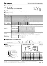
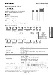
<strong>Radial</strong> <strong>Lead</strong> Type<br />
Series: FC Type: A<br />
■ Features<br />
● Endurance : 105 °C 1000 h to 5000 h<br />
● Low impedance<br />
● RoHS directive compliant<br />
Pressure relief<br />
φ6.3<<br />
But exclude 7 mm<br />
height<br />
Sleeve<br />
L ✽<br />
✽ L20 :L±2.0<br />
φd±0.05<br />
14 min. 3 min.<br />
(✽φ815, φ1615, φ1815 :L±1.5)<br />
<strong>Aluminum</strong> Electrolytic Capacitors/ FC<br />
■ Specifi cations<br />
Category Temp. Range –55 °C to +105 °C<br />
Rated W.V. Range 6.3 V.DC to 100 V.DC<br />
Nominal Cap. Range 1.0 µF to 15000 µF<br />
Capacitance Tolerance ±20 % (120 Hz/+20 °C)<br />
DC Leakage Cur rent I < 0.01 CV or 3 (µA) After 2 minutes (Whichever is greater)<br />
tan δ<br />
Endurance<br />
Shelf Life<br />
W.V.(V.DC) Cap (µF)<br />
6.3 to 100<br />
W.V. (V) 6.3 10 16 25 35 50 63 100<br />
tan δ 0.22 0.19 0.16 0.14 0.12 0.10 0.08 0.07<br />
For capacitance value > 1000 µF, add 0.02 per every 1000 µF.<br />
Design and specifi cations are each subject to change without notice. Ask factory for the current technical specifi cations before purchase and/or use.<br />
Should a safety concern arise regarding this product, please be sure to contact us immediately.<br />
–<br />
+<br />
– EEE-63 –<br />
φ4 toφ8<br />
φD±0.5 F±0.5<br />
φ10<<br />
φD±0.5<br />
(120 Hz/+20 °C)<br />
After following life test with DC voltage and +105 °C±2 °C ripple current value applied (The sum of DC<br />
and ripple peak voltage shall not exceed the rated working voltage) when the capacitors are restored to<br />
20 °C, the capacitors shall meet the limits specifi ed bellow.<br />
Duration : φ4 to φ6.3: 1000 hours, φ8: 2000 hours , φ10: 3000 hours , φ12.5 to φ18: 5000 hours<br />
Capacitance change ±20 % of initial measured value<br />
tan δ < 200 % of initial specifi ed value<br />
DC leakage current < initial specifi ed value<br />
■ Frequency correction factor for ripple current<br />
After storage for 1000 hours at +105 °C±2 °C with no voltage applied and then being stabilized at +20 °C,<br />
capacitors shall meet the limits specifi ed in Endurance. (With voltage treatment)<br />
60 120<br />
Frequency (Hz)<br />
1 k 10 k 100 k<br />
1.0 to 330 0.55 0.65 0.85 0.90 1.00<br />
390 to 1000 0.70 0.75 0.90 0.95 1.00<br />
1200 to 2200 0.75 0.80 0.90 0.95 1.00<br />
2700 to 15000 0.80 0.85 0.95 1.00 1.00<br />
■ Di men sions in mm (not to scale) (Unit : mm)<br />
L>11 L=7<br />
Body Dia. φD 4 5 6.3 8 10 12.5 16 18 4 5 6.3<br />
Body Length L 15 to 25 30 to 40<br />
<strong>Lead</strong> Dia. φd 0.45 0.5 0.5 0.6 0.6 0.6 0.8 0.8 0.8 0.45 0.45 0.45<br />
<strong>Lead</strong> space F 1.5 2.0 2.5 3.5 5.0 5.0 5.0 7.5 7.5 1.5 2.0 2.5<br />
00 Nov. 2012
■ Case size/ Impedance/ Ripple Current<br />
<strong>Aluminum</strong> Electrolytic Capacitors/ FC<br />
W.V(V.DC) 6.3 V to 35 V 50 V 63 V 100 V<br />
Case size<br />
(φDL)<br />
Imped ance<br />
()/(100 kHz)<br />
Ripple<br />
Current<br />
(mA r.m.s)<br />
/(100 kHz)<br />
Imped ance<br />
()/(100 kHz)<br />
Ripple<br />
Current<br />
(mA r.m.s)<br />
/(100 kHz)<br />
Design and specifi cations are each subject to change without notice. Ask factory for the current technical specifi cations before purchase and/or use.<br />
Should a safety concern arise regarding this product, please be sure to contact us immediately.<br />
– EEE-64 –<br />
Imped ance<br />
()/(100 kHz)<br />
Ripple<br />
Current<br />
(mA r.m.s)<br />
/(100 kHz)<br />
Imped ance<br />
()/(100 kHz)<br />
20 °C –10 °C 20 °C –10 °C 20 °C –10 °C 20 °C –10 °C<br />
4 7 2.00 5.00 65<br />
5 7 0.950 2.40 120<br />
6.3 7 0.450 1.20 200<br />
4 11 1.30 2.60 120 2.50 5.00 90 3.50 7.00 80<br />
5 11 0.800 1.60 175<br />
2.40 ✽14.80 ✽1 ✽3<br />
✽2, ✽3 ✽2, ✽3 ✽3<br />
Ripple<br />
Current<br />
(mA r.m.s)<br />
/(100 kHz)<br />
2.00 4.00 145 4.10 8.20 80<br />
5 15 0.500 1.00 235 0.900 1.80 215 1.30 2.60 200 2.80 5.60 90<br />
6.3 11.2 0.350 0.700 290 0.600 1.20 260 1.00 2.00 240 1.80 3.60 114<br />
6.3 15 0.250 0.500 400 0.400 0.800 360 0.700 1.40 330 1.10 2.20 155<br />
8 11.5 0.117 0.234 555 0.234 0.468 485 0.342 0.684 405 0.680 1.36 260<br />
8 15 0.085 0.170 730 0.155 0.310 635 0.230 0.460 535 0.450 0.900 340<br />
8 20 0.065 0.130 995 0.120 0.240 860 0.178 0.356 690 0.330 0.660 455<br />
10 12.5 0.090 0.180 755 0.162 0.324 615 0.256 0.512 535 0.530 1.06 306<br />
10 16 0.068 0.136 1050 0.119 0.238 850 0.194 0.388 600 0.360 0.720 400<br />
10 20 0.052 0.104 1220 0.090 0.180 1030 0.147 0.294 885 0.240 0.480 463<br />
10 25 0.045 0.090 1440 0.082 0.164 1200 0.130 0.260 1050 0.210 0.420 599<br />
10 30 0.035 0.070 1815 0.060 0.120 1610 0.090 0.180 1300 0.150 0.300 698<br />
12.5 15 0.065 0.130 1205 0.110 0.220 1150 0.150 0.300 1020 0.230 0.460 511<br />
12.5 20 0.038 0.076 1655 0.063 0.126 1480 0.085 0.170 1285 0.180 0.360 671<br />
12.5 25 0.030 0.060 1945 0.050 0.100 1832 0.070 0.140 1720 0.110 0.220 807<br />
12.5 30 0.025 0.050 2310 0.040 0.080 2215 0.055 0.110 2090 0.098 0.196 937<br />
12.5 35 0.022 0.044 2510 0.034 0.068 2285 0.047 0.094 2265 0.087 0.174 1040<br />
12.5 40 0.018 0.036 2655 0.030 0.060 2590 0.042 0.084 2560 0.072 0.144 1130<br />
16 15 0.043 0.086 1690 0.080 0.160 1610 0.090 0.180 1410 0.140 0.280 793<br />
16 20 0.029 0.058 2205 0.048 0.096 1835 0.059 0.118 1765 0.110 0.220 995<br />
16 25 0.022 0.044 2555 0.034 0.068 2235 0.050 0.100 2160 0.089 0.178 1170<br />
16 31.5 0.018 0.036 3010 0.028 0.056 2700 0.043 0.086 2670 0.062 0.124 1520<br />
16 35.5 0.016 0.032 3150 0.025 0.050 2790 0.036 0.072 2770 0.053 0.106 1730<br />
16 40 0.015 0.030 3360 0.023 0.046 2845 0.030 0.060 2825 0.047 0.094 1920<br />
18 15 0.038 0.076 2000 0.068 0.136 1900 0.086 0.172 1690 0.120 0.240 917<br />
18 20 0.028 0.056 2490 0.042 0.084 2420 0.055 0.110 2290 0.080 0.160 1230<br />
18 25 0.020 0.040 2740 0.029 0.058 2610 0.043 0.086 2585 0.070 0.140 1420<br />
18 31.5 0.016 0.032 3635 0.025 0.050 3000 0.032 0.064 2950 0.062 0.124 1600<br />
18 35.5 0.015 0.030 3680 0.023 0.046 3100 0.030 0.060 3095 0.041 0.082 1770<br />
18 40 0.014 0.028 3735 – – – 0.025 0.050 3205 0.036 0.072 2300<br />
✽1 : Apply to 1 µF<br />
✽2 : Apply to 2.2, 3.3, 4.7, 10L, 12, 18 and 22 µF<br />
✽3<br />
Case size<br />
(φDL)<br />
5 11<br />
Capacitance<br />
(µF)<br />
Imped ance ()/(100 kHz) Ripple Current<br />
(mA r.m.s)(100 kHz)<br />
20 °C –10 °C<br />
1.0 2.40 4.80 20<br />
2.2 1.80 3.60 45<br />
3.3 1.30 2.60 65<br />
4.7 1.30 2.60 95<br />
10L 1.30 2.60 125<br />
12 1.30 2.60 135<br />
15 1.30 2.60 145<br />
18 1.30 2.60 155<br />
22 1.30 2.60 155<br />
00 Nov. 2012
■ Standard Prod ucts<br />
Case size Specifi cation <strong>Lead</strong> Length<br />
<strong>Aluminum</strong> Electrolytic Capacitors/ FC<br />
Design and specifi cations are each subject to change without notice. Ask factory for the current technical specifi cations before purchase and/or use.<br />
Should a safety concern arise regarding this product, please be sure to contact us immediately.<br />
– EEE-65 –<br />
Min. Packaging Q'ty<br />
W.V. Cap.<br />
(±20 %) Dia.<br />
Ripple ImpedEndur- Current anceance Length<br />
(100 kHz) (100 kHz)<br />
(+105 °C) (+20 °C)<br />
<strong>Lead</strong><br />
Dia.<br />
<strong>Lead</strong> Space<br />
Part No.<br />
Straight<br />
<strong>Lead</strong>s Taping<br />
Straight Taping Taping<br />
✽B ✽H<br />
(V) (µF) (mm) (mm) (mA r.m.s.) () (hours) (mm) (mm) (mm) (mm) (pcs) (pcs)<br />
6.3<br />
27 4 7 65 2.000 1000 0.45 1.5 5.0 2.5 EEAFC0J270( ) 200 2000<br />
56 5 7 120 0.950 1000 0.45 2.0 5.0 2.5 EEAFC0J560( ) 200 2000<br />
68 4 11 120 1.300 1000 0.45 1.5 5.0 2.5 EEUFC0J680( ) 200 2000<br />
100 5 11 175 0.800 1000 0.50 2.0 5.0 2.5 EEUFC0J101( ) 200 2000<br />
120 6.3 7 200 0.450 1000 0.45 2.5 5.0 2.5 EEAFC0J121( ) 200 2000<br />
150 5 15 235 0.500 1000 0.50 2.0 5.0 2.5 EEUFC0J151( ) 200 2000<br />
220 6.3 11.2 290 0.350 1000 0.50 2.5 5.0 2.5 EEUFC0J221( ) 200 2000<br />
270 6.3 11.2 290 0.350 1000 0.50 2.5 5.0 2.5 EEUFC0J271( ) 200 2000<br />
330<br />
6.3<br />
6.3<br />
11.2<br />
15<br />
290<br />
400<br />
0.350<br />
0.250<br />
1000<br />
1000<br />
0.50<br />
0.50<br />
2.5<br />
2.5<br />
5.0<br />
5.0<br />
2.5<br />
2.5<br />
EEUFC0J331S( )<br />
EEUFC0J331( )<br />
200<br />
200<br />
2000<br />
2000<br />
390 8 11.5 555 0.117 2000 0.60 3.5 5.0 EEUFC0J391( ) 200 1000<br />
470 8 11.5 555 0.117 2000 0.60 3.5 5.0 EEUFC0J471( ) 200 1000<br />
560 8 11.5 555 0.117 2000 0.60 3.5 5.0 EEUFC0J561( ) 200 1000<br />
8<br />
820<br />
10<br />
15<br />
12.5<br />
730<br />
755<br />
0.085<br />
0.090<br />
2000<br />
3000<br />
0.60<br />
0.60<br />
3.5<br />
5.0<br />
5.0<br />
5.0<br />
EEUFC0J821L( )<br />
EEUFC0J821( )<br />
200<br />
200<br />
1000<br />
500<br />
1000 10 12.5 755 0.090 3000 0.60 5.0 5.0 EEUFC0J102( ) 200 500<br />
1200<br />
8 20 995 0.065 2000 0.60 3.5 5.0 EEUFC0J122L( ) 200 1000<br />
10 16 1050 0.068 3000 0.60 5.0 5.0 EEUFC0J122( ) 200 500<br />
10<br />
1500<br />
12.5<br />
20<br />
15<br />
1220<br />
1205<br />
0.052<br />
0.065<br />
3000<br />
5000<br />
0.60<br />
0.60<br />
5.0<br />
5.0<br />
5.0<br />
5.0<br />
EEUFC0J152( )<br />
EEUFC0J152S( )<br />
200<br />
200<br />
500<br />
500<br />
1800 10 25 1440 0.045 3000 0.60 5.0 5.0 EEUFC0J182( ) 200 500<br />
2200<br />
2700<br />
10 25 1440 0.045 3000 0.60 5.0 5.0 EEUFC0J222( ) 200 500<br />
16 15 1690 0.043 5000 0.80 7.5 7.5 EEUFC0J222S( ) 100 250<br />
10 30 1815 0.035 3000 0.60 5.0 EEUFC0J272L 100<br />
12.5 20 1655 0.038 5000 0.60 5.0 5.0 EEUFC0J272( ) 200 500<br />
16 15 1690 0.043 5000 0.80 7.5 7.5 EEUFC0J272S( ) 100 250<br />
12.5<br />
3300<br />
18<br />
20<br />
15<br />
1655<br />
2000<br />
0.038<br />
0.038<br />
5000<br />
5000<br />
0.60<br />
0.80<br />
5.0<br />
7.5<br />
5.0<br />
7.5<br />
EEUFC0J332( )<br />
EEUFC0J332S( )<br />
200<br />
100<br />
500<br />
250<br />
3900 12.5 25 1945 0.030 5000 0.60 5.0 5.0 EEUFC0J392( ) 200 500<br />
4700<br />
5600<br />
6800<br />
12.5 30 2310 0.025 5000 0.80 5.0 EEUFC0J472 100<br />
16 20 2205 0.029 5000 0.80 7.5 7.5 EEUFC0J472S( ) 100 250<br />
12.5 35 2510 0.022 5000 0.80 5.0 EEUFC0J562L 100<br />
16 20 2205 0.029 5000 0.80 7.5 7.5 EEUFC0J562( ) 100 250<br />
12.5 40 2655 0.018 5000 0.80 5.0 EEUFC0J682L 100<br />
16 25 2555 0.022 5000 0.80 7.5 7.5 EEUFC0J682( ) 100 250<br />
18 20 2490 0.028 5000 0.80 7.5 7.5 EEUFC0J682S( ) 100 250<br />
8200 16 31.5 3010 0.018 5000 0.80 7.5 EEUFC0J822 100<br />
10000<br />
Endurance : 105 °C φ4 to φ6.3=1000 h, φ8=2000 h, φ10=3000 h, φ12.5 to φ18=5000 h<br />
16 35.5 3150 0.016 5000 0.80 7.5 EEUFC0J103 100<br />
18 25 2740 0.020 5000 0.80 7.5 7.5 EEUFC0J103S( ) 100 250<br />
16<br />
12000<br />
18<br />
40<br />
31.5<br />
3360<br />
3635<br />
0.015<br />
0.016<br />
5000<br />
5000<br />
0.80<br />
0.80<br />
7.5<br />
7.5<br />
EEUFC0J123L<br />
EEUFC0J123<br />
100<br />
50<br />
15000 18 35.5 3680 0.015 5000 0.80 7.5 EEUFC0J153 50<br />
· When requesting taped product, please put the letter "B" or "H" be tween the "( )". <strong>Lead</strong> wire pitch B=5 mm, 7.5 mm, H=2.5 mm.<br />
· Please refer to the page of “Taping Dimensions”.<br />
00 Nov. 2012
■ Standard Prod ucts<br />
Case size Specifi cation <strong>Lead</strong> Length<br />
<strong>Aluminum</strong> Electrolytic Capacitors/ FC<br />
Design and specifi cations are each subject to change without notice. Ask factory for the current technical specifi cations before purchase and/or use.<br />
Should a safety concern arise regarding this product, please be sure to contact us immediately.<br />
– EEE-66 –<br />
Min. Packaging Q'ty<br />
W.V. Cap.<br />
(±20 %) Dia.<br />
Ripple ImpedEndur- Current anceance Length<br />
(100 kHz) (100 kHz)<br />
(+105 °C) (+20 °C)<br />
<strong>Lead</strong><br />
Dia.<br />
<strong>Lead</strong> Space<br />
Part No.<br />
Straight<br />
<strong>Lead</strong>s Taping<br />
Straight Taping Taping<br />
✽B ✽H<br />
(V) (µF) (mm) (mm) (mA r.m.s.) () (hours) (mm) (mm) (mm) (mm) (pcs) (pcs)<br />
10<br />
22 4 7 65 2.000 1000 0.45 1.5 5.0 2.5 EEAFC1A220( ) 200 2000<br />
39 5 7 120 0.950 1000 0.45 2.0 5.0 2.5 EEAFC1A390( ) 200 2000<br />
47 4 11 120 1.300 1000 0.45 1.5 5.0 2.5 EEUFC1A470( ) 200 2000<br />
82<br />
5 11 175 0.800 1000 0.50 2.0 5.0 2.5 EEUFC1A820( ) 200 2000<br />
6.3 7 200 0.450 1000 0.45 2.5 5.0 2.5 EEAFC1A820( ) 200 2000<br />
100<br />
5<br />
5<br />
11<br />
15<br />
175<br />
235<br />
0.800<br />
0.500<br />
1000<br />
1000<br />
0.50<br />
0.50<br />
2.0<br />
2.0<br />
5.0<br />
5.0<br />
2.5<br />
2.5<br />
EEUFC1A101S( )<br />
EEUFC1A101( )<br />
200<br />
200<br />
2000<br />
2000<br />
150 6.3 11.2 290 0.350 1000 0.50 2.5 5.0 2.5 EEUFC1A151( ) 200 2000<br />
180 6.3 11.2 290 0.350 1000 0.50 2.5 5.0 2.5 EEUFC1A181( ) 200 2000<br />
220<br />
6.3<br />
6.3<br />
11.2<br />
15<br />
290<br />
400<br />
0.350<br />
0.250<br />
1000<br />
1000<br />
0.50<br />
0.50<br />
2.5<br />
2.5<br />
5.0<br />
5.0<br />
2.5<br />
2.5<br />
EEUFC1A221S( )<br />
EEUFC1A221( )<br />
200<br />
200<br />
2000<br />
2000<br />
330 8 11.5 555 0.117 2000 0.60 3.5 5.0 EEUFC1A331( ) 200 1000<br />
390 8 11.5 555 0.117 2000 0.60 3.5 5.0 EEUFC1A391( ) 200 1000<br />
470 8 11.5 555 0.117 2000 0.60 3.5 5.0 EEUFC1A471( ) 200 1000<br />
560 10 12.5 755 0.090 3000 0.60 5.0 5.0 EEUFC1A561( ) 200 500<br />
680<br />
8<br />
10<br />
15<br />
12.5<br />
730<br />
755<br />
0.085<br />
0.090<br />
2000<br />
3000<br />
0.60<br />
0.60<br />
3.5<br />
5.0<br />
5.0<br />
5.0<br />
EEUFC1A681L( )<br />
EEUFC1A681( )<br />
200<br />
200<br />
1000<br />
500<br />
820 10 16 1050 0.068 3000 0.60 5.0 5.0 EEUFC1A821( ) 200 500<br />
1000<br />
8 20 995 0.065 2000 0.60 3.5 5.0 EEUFC1A102L( ) 200 1000<br />
10 16 1050 0.068 3000 0.60 5.0 5.0 EEUFC1A102( ) 200 500<br />
1200<br />
10<br />
12.5<br />
20<br />
15<br />
1220<br />
1205<br />
0.052<br />
0.065<br />
3000<br />
5000<br />
0.60<br />
0.60<br />
5.0<br />
5.0<br />
5.0<br />
5.0<br />
EEUFC1A122( )<br />
EEUFC1A122S( )<br />
200<br />
200<br />
500<br />
500<br />
1500 10 25 1440 0.045 3000 0.60 5.0 5.0 EEUFC1A152( ) 200 500<br />
1800<br />
2200<br />
2700<br />
3300<br />
3900<br />
4700<br />
5600<br />
6800<br />
Endurance : 105 °C φ4 to φ6.3=1000 h, φ8=2000 h, φ10=3000 h, φ12.5 to φ18=5000 h<br />
12.5 20 1655 0.038 5000 0.60 5.0 5.0 EEUFC1A182( ) 200 500<br />
16 15 1690 0.043 5000 0.80 7.5 7.5 EEUFC1A182S( ) 100 250<br />
10 30 1815 0.035 3000 0.60 5.0 EEUFC1A222L 100<br />
12.5 20 1655 0.038 5000 0.60 5.0 5.0 EEUFC1A222( ) 200 500<br />
12.5 25 1945 0.030 5000 0.60 5.0 5.0 EEUFC1A272( ) 200 500<br />
18 15 2000 0.038 5000 0.80 7.5 7.5 EEUFC1A272S( ) 100 250<br />
12.5 30 2310 0.025 5000 0.80 5.0 EEUFC1A332 100<br />
16 20 2205 0.029 5000 0.80 7.5 7.5 EEUFC1A332S( ) 100 250<br />
12.5 35 2510 0.022 5000 0.80 5.0 EEUFC1A392L 100<br />
16 20 2205 0.029 5000 0.80 7.5 7.5 EEUFC1A392( ) 100 250<br />
12.5 40 2655 0.018 5000 0.80 5.0 EEUFC1A472L 100<br />
16 25 2555 0.022 5000 0.80 7.5 7.5 EEUFC1A472( ) 100 250<br />
16 25 2555 0.022 5000 0.80 7.5 7.5 EEUFC1A562( ) 100 250<br />
18 20 2490 0.028 5000 0.80 7.5 7.5 EEUFC1A562S( ) 100 250<br />
16 31.5 3010 0.018 5000 0.80 7.5 EEUFC1A682 100<br />
18 25 2740 0.020 5000 0.80 7.5 7.5 EEUFC1A682S( ) 100 250<br />
8200<br />
16<br />
18<br />
35.5<br />
31.5<br />
3150<br />
3635<br />
0.016<br />
0.016<br />
5000<br />
5000<br />
0.80<br />
0.80<br />
7.5<br />
7.5<br />
EEUFC1A822L<br />
EEUFC1A822<br />
100<br />
50<br />
10000 18 35.5 3680 0.015 5000 0.80 7.5 EEUFC1A103 50<br />
12000 18 40 3735 0.014 5000 0.80 7.5 EEUFC1A123 50<br />
· When requesting taped product, please put the letter "B" or "H" be tween the "( )". <strong>Lead</strong> wire pitch B=5 mm, 7.5 mm, H=2.5 mm.<br />
· Please refer to the page of “Taping Dimensions”.<br />
00 Nov. 2012
■ Standard Prod ucts<br />
Case size Specifi cation <strong>Lead</strong> Length<br />
<strong>Aluminum</strong> Electrolytic Capacitors/ FC<br />
Design and specifi cations are each subject to change without notice. Ask factory for the current technical specifi cations before purchase and/or use.<br />
Should a safety concern arise regarding this product, please be sure to contact us immediately.<br />
– EEE-67 –<br />
Min. Packaging Q'ty<br />
W.V. Cap.<br />
(±20 %) Dia.<br />
Ripple ImpedEndur- Current anceance Length<br />
(100 kHz) (100 kHz)<br />
(+105 °C) (+20 °C)<br />
<strong>Lead</strong><br />
Dia.<br />
<strong>Lead</strong> Space<br />
Part No.<br />
Straight<br />
<strong>Lead</strong>s Taping<br />
Straight Taping Taping<br />
✽B ✽H<br />
(V) (µF) (mm) (mm) (mA r.m.s.) () (hours) (mm) (mm) (mm) (mm) (pcs) (pcs)<br />
16<br />
15 4 7 65 2.000 1000 0.45 1.5 5.0 2.5 EEAFC1C150( ) 200 2000<br />
27 5 7 120 0.950 1000 0.45 2.0 5.0 2.5 EEAFC1C270( ) 200 2000<br />
39 4 11 120 1.30 1000 0.45 1.5 5.0 2.5 EEUFC1C390( ) 200 2000<br />
47 5 11 175 0.800 1000 0.50 2.0 5.0 2.5 EEUFC1C470( ) 200 2000<br />
56<br />
5<br />
6.3<br />
11<br />
7<br />
175<br />
200<br />
0.800<br />
0.450<br />
1000<br />
1000<br />
0.50<br />
0.45<br />
2.0<br />
2.5<br />
5.0<br />
5.0<br />
2.5<br />
2.5<br />
EEUFC1C560( )<br />
EEAFC1C560( )<br />
200<br />
200<br />
2000<br />
2000<br />
68 5 11 175 0.800 1000 0.50 2.0 5.0 2.5 EEUFC1C680( ) 200 2000<br />
82 5 15 235 0.500 1000 0.50 2.0 5.0 2.5 EEUFC1C820( ) 200 2000<br />
100 6.3 11.2 290 0.350 1000 0.50 2.5 5.0 2.5 EEUFC1C101( ) 200 2000<br />
120 6.3 11.2 290 0.350 1000 0.50 2.5 5.0 2.5 EEUFC1C121( ) 200 2000<br />
180 6.3 15 400 0.250 1000 0.50 2.5 5.0 2.5 EEUFC1C181( ) 200 2000<br />
220 8 11.5 555 0.117 2000 0.60 3.5 5.0 EEUFC1C221( ) 200 1000<br />
270 8 11.5 555 0.117 2000 0.60 3.5 5.0 EEUFC1C271( ) 200 1000<br />
330 8 11.5 555 0.117 2000 0.60 3.5 5.0 EEUFC1C331( ) 200 1000<br />
390 10 12.5 755 0.090 3000 0.60 5.0 5.0 EEUFC1C391( ) 200 500<br />
470<br />
8<br />
10<br />
15<br />
12.5<br />
730<br />
755<br />
0.085<br />
0.090<br />
2000<br />
3000<br />
0.60<br />
0.60<br />
3.5<br />
5.0<br />
5.0<br />
5.0<br />
EEUFC1C471L( )<br />
EEUFC1C471( )<br />
200<br />
200<br />
1000<br />
500<br />
560 10 16 1050 0.068 3000 0.60 5.0 5.0 EEUFC1C561( ) 200 500<br />
680<br />
820<br />
1000<br />
1200<br />
1500<br />
1800<br />
2200<br />
2700<br />
3300<br />
3900<br />
4700<br />
Endurance : 105 °C φ4 to φ6.3=1000 h, φ8=2000 h, φ10=3000 h, φ12.5 to φ18=5000 h<br />
8 20 995 0.065 2000 0.60 3.5 5.0 EEUFC1C681L( ) 200 1000<br />
10 16 1050 0.068 3000 0.60 5.0 5.0 EEUFC1C681( ) 200 500<br />
10 20 1220 0.052 3000 0.60 5.0 5.0 EEUFC1C821( ) 200 500<br />
12.5 15 1205 0.065 5000 0.60 5.0 5.0 EEUFC1C821S( ) 200 500<br />
10 20 1220 0.052 3000 0.60 5.0 5.0 EEUFC1C102S( ) 200 500<br />
10 25 1440 0.045 3000 0.60 5.0 5.0 EEUFC1C102( ) 200 500<br />
10 25 1440 0.045 3000 0.60 5.0 5.0 EEUFC1C122( ) 200 500<br />
16 15 1690 0.043 5000 0.80 7.5 7.5 EEUFC1C122S( ) 100 250<br />
10 30 1815 0.035 3000 0.60 5.0 EEUFC1C152L 100<br />
12.5 20 1655 0.038 5000 0.60 5.0 5.0 EEUFC1C152( ) 200 500<br />
16 15 1690 0.043 5000 0.80 7.5 7.5 EEUFC1C152S( ) 100 250<br />
12.5 25 1945 0.030 5000 0.60 5.0 5.0 EEUFC1C182( ) 200 500<br />
18 15 2000 0.038 5000 0.80 7.5 7.5 EEUFC1C182S( ) 100 250<br />
12.5 25 1945 0.030 5000 0.60 5.0 5.0 EEUFC1C222( ) 200 500<br />
16 20 2205 0.029 5000 0.80 7.5 7.5 EEUFC1C222S( ) 100 250<br />
12.5 30 2310 0.025 5000 0.80 5.0 EEUFC1C272L 100<br />
16 20 2205 0.029 5000 0.80 7.5 7.5 EEUFC1C272( ) 100 250<br />
12.5 35 2510 0.022 5000 0.80 5.0 EEUFC1C332 100<br />
18 20 2490 0.028 5000 0.80 7.5 7.5 EEUFC1C332S( ) 100 250<br />
16 25 2555 0.022 5000 0.80 7.5 7.5 EEUFC1C392( ) 100 250<br />
18 20 2490 0.028 5000 0.80 7.5 7.5 EEUFC1C392S( ) 100 250<br />
16 31.5 3010 0.018 5000 0.80 7.5 EEUFC1C472 100<br />
18 25 2740 0.020 5000 0.80 7.5 7.5 EEUFC1C472S( ) 100 250<br />
5600<br />
16<br />
18<br />
35.5<br />
31.5<br />
3150<br />
3635<br />
0.016<br />
0.016<br />
5000<br />
5000<br />
0.80<br />
0.80<br />
7.5<br />
7.5<br />
EEUFC1C562L<br />
EEUFC1C562<br />
100<br />
50<br />
6800 16 40 3360 0.015 5000 0.80 7.5 EEUFC1C682 100<br />
8200 18 35.5 3680 0.015 5000 0.80 7.5 EEUFC1C822 50<br />
· When requesting taped product, please put the letter "B" or "H" be tween the "( )". <strong>Lead</strong> wire pitch B=5 mm, 7.5 mm, H=2.5 mm.<br />
· Please refer to the page of “Taping Dimensions”.<br />
00 Nov. 2012
■ Standard Prod ucts<br />
Case size Specifi cation <strong>Lead</strong> Length<br />
<strong>Aluminum</strong> Electrolytic Capacitors/ FC<br />
Design and specifi cations are each subject to change without notice. Ask factory for the current technical specifi cations before purchase and/or use.<br />
Should a safety concern arise regarding this product, please be sure to contact us immediately.<br />
– EEE-68 –<br />
Min. Packaging Q'ty<br />
W.V. Cap.<br />
(±20 %) Dia.<br />
Ripple ImpedEndur- Current anceance Length<br />
(100 kHz) (100 kHz)<br />
(+105 °C) (+20 °C)<br />
<strong>Lead</strong><br />
Dia.<br />
<strong>Lead</strong> Space<br />
Part No.<br />
Straight<br />
<strong>Lead</strong>s Taping<br />
Straight Taping Taping<br />
✽B ✽H<br />
(V) (µF) (mm) (mm) (mA r.m.s.) () (hours) (mm) (mm) (mm) (mm) (pcs) (pcs)<br />
25<br />
10 4 7 65 2.000 1000 0.45 1.5 5.0 2.5 EEAFC1E100( ) 200 2000<br />
22 5 7 120 0.950 1000 0.45 2.0 5.0 2.5 EEAFC1E220( ) 200 2000<br />
27 4 11 120 1.30 1000 0.45 1.5 5.0 2.5 EEUFC1E270( ) 200 2000<br />
39<br />
5<br />
6.3<br />
11<br />
7<br />
175<br />
200<br />
0.800<br />
0.450<br />
1000<br />
1000<br />
0.50<br />
0.45<br />
2.0<br />
2.5<br />
5.0<br />
5.0<br />
2.5<br />
2.5<br />
EEUFC1E390( )<br />
EEAFC1E390( )<br />
200<br />
200<br />
2000<br />
2000<br />
47 5 11 175 0.800 1000 0.50 2.0 5.0 2.5 EEUFC1E470( ) 200 2000<br />
56 5 15 235 0.500 1000 0.50 2.0 5.0 2.5 EEUFC1E560( ) 200 2000<br />
82 6.3 11.2 290 0.350 1000 0.50 2.5 5.0 2.5 EEUFC1E820( ) 200 2000<br />
100 6.3 11.2 290 0.350 1000 0.50 2.5 5.0 2.5 EEUFC1E101S( ) 200 2000<br />
120 6.3 15 400 0.250 1000 0.50 2.5 5.0 2.5 EEUFC1E121( ) 200 2000<br />
180 8 11.5 555 0.117 2000 0.60 3.5 5.0 EEUFC1E181( ) 200 1000<br />
220 8 11.5 555 0.117 2000 0.60 3.5 5.0 EEUFC1E221( ) 200 1000<br />
270 10 12.5 755 0.090 3000 0.60 5.0 5.0 EEUFC1E271( ) 200 500<br />
330<br />
8<br />
10<br />
15<br />
12.5<br />
730<br />
755<br />
0.085<br />
0.090<br />
2000<br />
3000<br />
0.60<br />
0.60<br />
3.5<br />
5.0<br />
5.0<br />
5.0<br />
EEUFC1E331L( )<br />
EEUFC1E331( )<br />
200<br />
200<br />
1000<br />
500<br />
390 10 16 1050 0.068 3000 0.60 5.0 5.0 EEUFC1E391( ) 200 500<br />
470<br />
8 20 995 0.065 2000 0.60 3.5 5.0 EEUFC1E471L( ) 200 1000<br />
10 16 1050 0.068 3000 0.60 5.0 5.0 EEUFC1E471( ) 200 500<br />
560<br />
10<br />
12.5<br />
20<br />
15<br />
1220<br />
1205<br />
0.052<br />
0.065<br />
3000<br />
5000<br />
0.60<br />
0.60<br />
5.0<br />
5.0<br />
5.0<br />
5.0<br />
EEUFC1E561( )<br />
EEUFC1E561S( )<br />
200<br />
200<br />
500<br />
500<br />
680 10 20 1220 0.052 3000 0.60 5.0 5.0 EEUFC1E681( ) 200 500<br />
820<br />
1000<br />
1200<br />
1500<br />
1800<br />
10 25 1440 0.045 3000 0.60 5.0 5.0 EEUFC1E821( ) 200 500<br />
12.5 20 1655 0.038 5000 0.60 5.0 5.0 EEUFC1E821S( ) 200 500<br />
10 30 1815 0.035 3000 0.60 5.0 EEUFC1E102L 100<br />
12.5 20 1655 0.038 5000 0.60 5.0 5.0 EEUFC1E102( ) 200 500<br />
16 15 1690 0.043 5000 0.80 7.5 7.5 EEUFC1E102S( ) 100 250<br />
12.5 25 1945 0.030 5000 0.60 5.0 5.0 EEUFC1E122( ) 200 500<br />
18 15 2000 0.038 5000 0.80 7.5 7.5 EEUFC1E122S( ) 100 250<br />
12.5 25 1945 0.030 5000 0.60 5.0 5.0 EEUFC1E152( ) 200 500<br />
16 20 2205 0.029 5000 0.80 7.5 7.5 EEUFC1E152S( ) 100 250<br />
12.5 30 2310 0.025 5000 0.80 5.0 EEUFC1E182L 100<br />
16 20 2205 0.029 5000 0.80 7.5 7.5 EEUFC1E182( ) 100 250<br />
2200<br />
12.5<br />
18<br />
35<br />
20<br />
2510<br />
2490<br />
0.022<br />
0.028<br />
5000<br />
5000<br />
0.80<br />
0.80<br />
5.0<br />
7.5 7.5<br />
EEUFC1E222<br />
EEUFC1E222S( )<br />
100<br />
100 250<br />
2700 16 25 2555 0.022 5000 0.80 7.5 7.5 EEUFC1E272( ) 100 250<br />
3300<br />
Endurance : 105 °C φ4 to φ6.3=1000 h, φ8=2000 h, φ10=3000 h, φ12.5 to φ18=5000 h<br />
16 31.5 3010 0.018 5000 0.80 7.5 EEUFC1E332 100<br />
18 25 2740 0.020 5000 0.80 7.5 7.5 EEUFC1E332S( ) 100 250<br />
3900<br />
16<br />
18<br />
35.5<br />
31.5<br />
3150<br />
3635<br />
0.016<br />
0.016<br />
5000<br />
5000<br />
0.80<br />
0.80<br />
7.5<br />
7.5<br />
EEUFC1E392L<br />
EEUFC1E392<br />
100<br />
50<br />
4700 18 35.5 3680 0.015 5000 0.80 7.5 EEUFC1E472 50<br />
5600 18 40 3735 0.014 5000 0.80 7.5 EEUFC1E562 50<br />
· When requesting taped product, please put the letter "B" or "H" be tween the "( )". <strong>Lead</strong> wire pitch B=5 mm, 7.5 mm, H=2.5 mm.<br />
· Please refer to the page of “Taping Dimensions”.<br />
00 Nov. 2012
■ Standard Prod ucts<br />
Case size Specifi cation <strong>Lead</strong> Length<br />
<strong>Aluminum</strong> Electrolytic Capacitors/ FC<br />
Design and specifi cations are each subject to change without notice. Ask factory for the current technical specifi cations before purchase and/or use.<br />
Should a safety concern arise regarding this product, please be sure to contact us immediately.<br />
– EEE-69 –<br />
Min. Packaging Q'ty<br />
W.V. Cap.<br />
(±20 %) Dia.<br />
Ripple ImpedEndur- Current anceance Length<br />
(100 kHz) (100 kHz)<br />
(+105 °C) (+20 °C)<br />
<strong>Lead</strong><br />
Dia.<br />
<strong>Lead</strong> Space<br />
Part No.<br />
Straight<br />
<strong>Lead</strong>s Taping<br />
Straight Taping Taping<br />
✽B ✽H<br />
(V) (µF) (mm) (mm) (mA r.m.s.) () (hours) (mm) (mm) (mm) (mm) (pcs) (pcs)<br />
35<br />
Endurance : 105 °C φ4 to φ6.3=1000 h, φ8=2000 h, φ10=3000 h, φ12.5 to φ18=5000 h<br />
6.8 4 7 65 2.000 1000 0.45 1.5 5.0 2.5 EEAFC1V6R8( ) 200 2000<br />
12 5 7 120 0.950 1000 0.45 2.0 5.0 2.5 EEAFC1V120( ) 200 2000<br />
18 4 11 120 1.300 1000 0.45 1.5 5.0 2.5 EEUFC1V180( ) 200 2000<br />
22 5 11 175 0.800 1000 0.50 2.0 5.0 2.5 EEUFC1V220( ) 200 2000<br />
27<br />
5<br />
6.3<br />
11<br />
7<br />
175<br />
200<br />
0.800<br />
0.450<br />
1000<br />
1000<br />
0.50<br />
0.45<br />
2.0<br />
2.5<br />
5.0<br />
5.0<br />
2.5<br />
2.5<br />
EEUFC1V270( )<br />
EEAFC1V270( )<br />
200<br />
200<br />
2000<br />
2000<br />
33 5 11 175 0.080 1000 0.50 2.0 5.0 2.5 EEUFC1V330( ) 200 2000<br />
39 5 15 235 0.500 1000 0.50 2.0 5.0 2.5 EEUFC1V390( ) 200 2000<br />
47 6.3 11.2 290 0.350 1000 0.50 2.5 5.0 2.5 EEUFC1V470( ) 200 2000<br />
56 6.3 11.2 290 0.350 1000 0.50 2.5 5.0 2.5 EEUFC1V560( ) 200 2000<br />
68 6.3 11.2 290 0.350 1000 0.50 2.5 5.0 2.5 EEUFC1V680( ) 200 2000<br />
82 6.3 15 400 0.250 1000 0.50 2.5 5.0 2.5 EEUFC1V820( ) 200 2000<br />
100 8 11.5 555 0.117 2000 0.60 3.5 5.0 EEUFC1V101( ) 200 1000<br />
120 8 11.5 555 0.117 2000 0.60 3.5 5.0 EEUFC1V121( ) 200 1000<br />
150 8 11.5 555 0.117 2000 0.60 3.5 5.0 EEUFC1V151( ) 200 1000<br />
180 10 12.5 755 0.090 3000 0.60 5.0 5.0 EEUFC1V181( ) 200 500<br />
220<br />
8<br />
10<br />
15<br />
12.5<br />
730<br />
755<br />
0.085<br />
0.090<br />
2000<br />
3000<br />
0.60<br />
0.60<br />
3.5<br />
5.0<br />
5.0<br />
5.0<br />
EEUFC1V221L( )<br />
EEUFC1V221( )<br />
200<br />
200<br />
1000<br />
500<br />
270 10 16 1050 0.068 3000 0.60 5.0 5.0 EEUFC1V271( ) 200 500<br />
330<br />
8<br />
10<br />
20<br />
16<br />
995<br />
1050<br />
0.065<br />
0.068<br />
2000<br />
3000<br />
0.60<br />
0.60<br />
3.5<br />
5.0<br />
5.0<br />
5.0<br />
EEUFC1V331L( )<br />
EEUFC1V331( )<br />
200<br />
200<br />
1000<br />
500<br />
390<br />
10<br />
12.5<br />
20<br />
15<br />
1220<br />
1205<br />
0.052<br />
0.065<br />
3000<br />
5000<br />
0.60<br />
0.60<br />
5.0<br />
5.0<br />
5.0<br />
5.0<br />
EEUFC1V391( )<br />
EEUFC1V391S( )<br />
200<br />
200<br />
500<br />
500<br />
470 10 20 1220 0.052 3000 0.60 5.0 5.0 EEUFC1V471( ) 200 500<br />
560<br />
10<br />
12.5<br />
25<br />
20<br />
1440<br />
1655<br />
0.045<br />
0.038<br />
3000<br />
5000<br />
0.60<br />
0.60<br />
5.0<br />
5.0<br />
5.0<br />
5.0<br />
EEUFC1V561( )<br />
EEUFC1V561S( )<br />
200<br />
200<br />
500<br />
500<br />
10 30 1815 0.035 3000 0.60 5.0 EEUFC1V681L 100<br />
680 12.5 20 1655 0.038 5000 0.60 5.0 5.0 EEUFC1V681( ) 200 500<br />
16 15 1690 0.043 5000 0.80 7.5 7.5 EEUFC1V681S( ) 100 250<br />
820<br />
12.5<br />
18<br />
25<br />
15<br />
1945<br />
2000<br />
0.030<br />
0.038<br />
5000<br />
5000<br />
0.60<br />
0.80<br />
5.0<br />
7.5<br />
5.0<br />
7.5<br />
EEUFC1V821L( )<br />
EEUFC1V821( )<br />
200<br />
100<br />
500<br />
250<br />
1000<br />
12.5<br />
16<br />
25<br />
20<br />
1945<br />
2205<br />
0.030<br />
0.029<br />
5000<br />
5000<br />
0.60<br />
0.80<br />
5.0<br />
7.5<br />
5.0<br />
7.5<br />
EEUFC1V102( )<br />
EEUFC1V102S( )<br />
200<br />
100<br />
500<br />
250<br />
1200<br />
12.5<br />
16<br />
30<br />
20<br />
2310<br />
2205<br />
0.025<br />
0.029<br />
5000<br />
5000<br />
0.80<br />
0.80<br />
5.0<br />
7.5 7.5<br />
EEUFC1V122L<br />
EEUFC1V122( )<br />
100<br />
100 250<br />
12.5 35 2510 0.022 5000 0.80 5.0 EEUFC1V152L 100<br />
1500 16 25 2555 0.022 5000 0.80 7.5 7.5 EEUFC1V152( ) 100 250<br />
18 20 2490 0.028 5000 0.80 7.5 7.5 EEUFC1V152S( ) 100 250<br />
12.5 40 2655 0.018 5000 0.80 5.0 EEUFC1V182L 100<br />
1800 16 25 2555 0.022 5000 0.80 7.5 7.5 EEUFC1V182( ) 100 250<br />
18 20 2490 0.028 5000 0.80 7.5 7.5 EEUFC1V182S( ) 100 250<br />
2200<br />
16<br />
18<br />
31.5<br />
25<br />
3010<br />
2740<br />
0.018<br />
0.020<br />
5000<br />
5000<br />
0.80<br />
0.80<br />
7.5<br />
7.5 7.5<br />
EEUFC1V222<br />
EEUFC1V222S( )<br />
100<br />
100 250<br />
2700<br />
16<br />
18<br />
35.5<br />
31.5<br />
3150<br />
3635<br />
0.016<br />
0.016<br />
5000<br />
5000<br />
0.80<br />
0.80<br />
7.5<br />
7.5<br />
EEUFC1V272L<br />
EEUFC1V272<br />
100<br />
50<br />
3300 18 35.5 3680 0.015 5000 0.80 7.5 EEUFC1V332 50<br />
3900 18 40 3735 0.014 5000 0.80 7.5 EEUFC1V392 50<br />
· When requesting taped product, please put the letter "B" or "H" be tween the "( )". <strong>Lead</strong> wire pitch B=5 mm, 7.5 mm, H=2.5 mm.<br />
· Please refer to the page of “Taping Dimensions”.<br />
00 Nov. 2012
■ Standard Prod ucts<br />
Case size Specifi cation <strong>Lead</strong> Length<br />
<strong>Aluminum</strong> Electrolytic Capacitors/ FC<br />
Design and specifi cations are each subject to change without notice. Ask factory for the current technical specifi cations before purchase and/or use.<br />
Should a safety concern arise regarding this product, please be sure to contact us immediately.<br />
– EEE-70 –<br />
Min. Packaging Q'ty<br />
W.V. Cap.<br />
(±20 %) Dia.<br />
Ripple ImpedEndur- Current anceance Length<br />
(100 kHz) (100 kHz)<br />
(+105 °C) (+20 °C)<br />
<strong>Lead</strong><br />
Dia.<br />
<strong>Lead</strong> Space<br />
Part No.<br />
Straight<br />
<strong>Lead</strong>s Taping<br />
Straight Taping Taping<br />
✽B ✽H<br />
(V) (µF) (mm) (mm) (mA r.m.s.) () (hours) (mm) (mm) (mm) (mm) (pcs) (pcs)<br />
50<br />
Endurance : 105 °C φ4 to φ6.3=1000 h, φ8=2000 h, φ10=3000 h, φ12.5 to φ18=5000 h<br />
1.0 5 11 20 2.400 1000 0.50 2.0 5.0 2.5 EEUFC1H1R0( ) 200 2000<br />
2.2 5 11 45 1.800 1000 0.50 2.0 5.0 2.5 EEUFC1H2R2( ) 200 2000<br />
3.3 5 11 65 1.300 1000 0.50 2.0 5.0 2.5 EEUFC1H3R3( ) 200 2000<br />
4.7 5 11 95 1.300 1000 0.50 2.0 5.0 2.5 EEUFC1H4R7( ) 200 2000<br />
10<br />
4<br />
5<br />
11<br />
11<br />
90<br />
125<br />
2.500<br />
1.300<br />
1000<br />
1000<br />
0.45<br />
0.50<br />
1.5<br />
2.0<br />
5.0<br />
5.0<br />
2.5<br />
2.5<br />
EEUFC1H100( )<br />
EEUFC1H100L( )<br />
200<br />
200<br />
2000<br />
2000<br />
12 5 11 135 1.300 1000 0.50 2.0 5.0 2.5 EEUFC1H120( ) 200 2000<br />
15 5 11 145 1.300 1000 0.50 2.0 5.0 2.5 EEUFC1H150( ) 200 2000<br />
18 5 11 155 1.300 1000 0.50 2.0 5.0 2.5 EEUFC1H180( ) 200 2000<br />
22 5 11 155 1.300 1000 0.50 2.0 5.0 2.5 EEUFC1H220( ) 200 2000<br />
27 5 15 215 0.900 1000 0.50 2.0 5.0 2.5 EEUFC1H270( ) 200 2000<br />
33 6.3 11.2 260 0.600 1000 0.50 2.5 5.0 2.5 EEUFC1H330( ) 200 2000<br />
39 6.3 11.2 260 0.600 1000 0.50 2.5 5.0 2.5 EEUFC1H390( ) 200 2000<br />
47 6.3 11.2 260 0.600 1000 0.50 2.5 5.0 2.5 EEUFC1H470( ) 200 2000<br />
56 6.3 15 360 0.400 1000 0.50 2.5 5.0 2.5 EEUFC1H560( ) 200 2000<br />
68 8 11.5 485 0.234 2000 0.60 3.5 5.0 EEUFC1H680( ) 200 1000<br />
82 8 11.5 485 0.234 2000 0.60 3.5 5.0 EEUFC1H820( ) 200 1000<br />
100 10 12.5 615 0.162 3000 0.60 5.0 5.0 EEUFC1H101( ) 200 500<br />
120<br />
8<br />
10<br />
15<br />
12.5<br />
635<br />
615<br />
0.155<br />
0.162<br />
2000<br />
3000<br />
0.60<br />
0.60<br />
3.5<br />
5.0<br />
5.0<br />
5.0<br />
EEUFC1H121L( )<br />
EEUFC1H121( )<br />
200<br />
200<br />
1000<br />
500<br />
150 10 16 850 0.119 3000 0.60 5.0 5.0 EEUFC1H151( ) 200 500<br />
180<br />
8<br />
10<br />
20<br />
16<br />
860<br />
850<br />
0.120<br />
0.119<br />
2000<br />
3000<br />
0.60<br />
0.60<br />
3.5<br />
5.0<br />
5.0<br />
5.0<br />
EEUFC1H181L( )<br />
EEUFC1H181( )<br />
200<br />
200<br />
1000<br />
500<br />
220<br />
10<br />
12.5<br />
20<br />
15<br />
1030<br />
1150<br />
0.090<br />
0.110<br />
3000<br />
5000<br />
0.60<br />
0.60<br />
5.0<br />
5.0<br />
5.0<br />
5.0<br />
EEUFC1H221( )<br />
EEUFC1H221S( )<br />
200<br />
200<br />
500<br />
500<br />
270 10 25 1200 0.082 3000 0.60 5.0 5.0 EEUFC1H271( ) 200 500<br />
330<br />
10<br />
12.5<br />
30<br />
20<br />
1610<br />
1480<br />
0.060<br />
0.063<br />
3000<br />
5000<br />
0.60<br />
0.60<br />
5.0<br />
5.0 5.0<br />
EEUFC1H331L<br />
EEUFC1H331( )<br />
100<br />
200 500<br />
390<br />
12.5<br />
16<br />
20<br />
15<br />
1480<br />
1610<br />
0.063<br />
0.080<br />
5000<br />
5000<br />
0.60<br />
0.80<br />
5.0<br />
7.5<br />
5.0<br />
7.5<br />
EEUFC1H391( )<br />
EEUFC1H391S( )<br />
200<br />
100<br />
500<br />
250<br />
470<br />
10<br />
12.5<br />
30<br />
25<br />
1610<br />
1832<br />
0.060<br />
0.050<br />
3000<br />
5000<br />
0.60<br />
0.60<br />
5.0<br />
5.0 5.0<br />
EEUFC1H471L<br />
EEUFC1H471( )<br />
100<br />
200 500<br />
560<br />
12.5<br />
18<br />
25<br />
15<br />
1832<br />
1900<br />
0.050<br />
0.068<br />
5000<br />
5000<br />
0.60<br />
0.80<br />
5.0<br />
7.5<br />
5.0<br />
7.5<br />
EEUFC1H561( )<br />
EEUFC1H561S( )<br />
200<br />
100<br />
500<br />
250<br />
680<br />
12.5<br />
16<br />
30<br />
20<br />
2215<br />
1835<br />
0.040<br />
0.048<br />
5000<br />
5000<br />
0.80<br />
0.80<br />
5.0<br />
7.5 7.5<br />
EEUFC1H681L<br />
EEUFC1H681( )<br />
100<br />
100 250<br />
820<br />
12.5<br />
18<br />
35<br />
20<br />
2285<br />
2420<br />
0.034<br />
0.042<br />
5000<br />
5000<br />
0.80<br />
0.80<br />
5.0<br />
7.5 7.5<br />
EEUFC1H821L<br />
EEUFC1H821( )<br />
100<br />
100 250<br />
1000<br />
12.5<br />
16<br />
40<br />
25<br />
2590<br />
2235<br />
0.030<br />
0.034<br />
5000<br />
5000<br />
0.80<br />
0.80<br />
5.0<br />
7.5 7.5<br />
EEUFC1H102L<br />
EEUFC1H102( )<br />
100<br />
100 250<br />
1200<br />
16<br />
18<br />
31.5<br />
25<br />
2700<br />
2610<br />
0.028<br />
0.029<br />
5000<br />
5000<br />
0.80<br />
0.80<br />
7.5<br />
7.5 7.5<br />
EEUFC1H122<br />
EEUFC1H122S( )<br />
100<br />
100 250<br />
1500 16 35.5 2790 0.025 5000 0.80 7.5 EEUFC1H152L 100<br />
1800<br />
16<br />
18<br />
40<br />
31.5<br />
2845<br />
3000<br />
0.023<br />
0.025<br />
5000<br />
5000<br />
0.80<br />
0.80<br />
7.5<br />
7.5<br />
EEUFC1H182L<br />
EEUFC1H182<br />
100<br />
50<br />
2200 18 35.5 3100 0.023 5000 0.80 7.5 EEUFC1H222 50<br />
· When requesting taped product, please put the letter "B" or "H" be tween the "( )". <strong>Lead</strong> wire pitch B=5 mm, 7.5 mm, H=2.5 mm.<br />
· Please refer to the page of “Taping Dimensions”.<br />
00 Nov. 2012
■ Standard Prod ucts<br />
Case size Specifi cation <strong>Lead</strong> Length<br />
<strong>Aluminum</strong> Electrolytic Capacitors/ FC<br />
Design and specifi cations are each subject to change without notice. Ask factory for the current technical specifi cations before purchase and/or use.<br />
Should a safety concern arise regarding this product, please be sure to contact us immediately.<br />
– EEE-71 –<br />
Min. Packaging Q'ty<br />
W.V.<br />
Cap.<br />
(±20 %) Dia.<br />
Ripple ImpedEndur- Current anceance Length<br />
(100 kHz) (100 kHz)<br />
(+105 °C) (+20 °C)<br />
<strong>Lead</strong><br />
Dia.<br />
<strong>Lead</strong> Space<br />
Part No.<br />
Straight<br />
<strong>Lead</strong>s Taping<br />
Straight Taping Taping<br />
✽B ✽H<br />
(V) (µF) (mm) (mm) (mA r.m.s.) () (hours) (mm) (mm) (mm) (mm) (pcs) (pcs)<br />
63<br />
6.8 4 11 80 3.500 1000 0.45 1.5 5.0 2.5 EEUFC1J6R8( ) 200 2000<br />
12 5 11 145 2.000 1000 0.50 2.0 5.0 2.5 EEUFC1J120( ) 200 2000<br />
18 5 15 200 1.300 1000 0.50 2.0 5.0 2.5 EEUFC1J180( ) 200 2000<br />
22 6.3 11.2 240 1.000 1000 0.50 2.5 5.0 2.5 EEUFC1J220( ) 200 2000<br />
33 6.3 11.2 240 1.000 1000 0.50 2.5 5.0 2.5 EEUFC1J330( ) 200 2000<br />
39 6.3 15 330 0.700 1000 0.50 2.5 5.0 2.5 EEUFC1J390( ) 200 2000<br />
47 8 11.5 405 0.342 2000 0.60 3.5 5.0 EEUFC1J470( ) 200 1000<br />
56 8 11.5 405 0.342 2000 0.60 3.5 5.0 EEUFC1J560( ) 200 1000<br />
68 8 11.5 405 0.342 2000 0.60 3.5 5.0 EEUFC1J680( ) 200 1000<br />
82 10 12.5 535 0.256 3000 0.60 5.0 5.0 EEUFC1J820( ) 200 500<br />
100<br />
8 15 535 0.230 2000 0.60 3.5 5.0 EEUFC1J101L( ) 200 1000<br />
10 12.5 535 0.256 3000 0.60 5.0 5.0 EEUFC1J101( ) 200 500<br />
120 10 16 600 0.194 3000 0.60 5.0 5.0 EEUFC1J121( ) 200 500<br />
150 8 20 690 0.178 2000 0.60 3.5 5.0 EEUFC1J151( ) 200 1000<br />
180<br />
220<br />
10 20 885 0.147 3000 0.60 5.0 5.0 EEUFC1J181( ) 200 500<br />
12.5 15 1020 0.150 5000 0.60 5.0 5.0 EEUFC1J181S( ) 200 500<br />
10 20 885 0.147 3000 0.60 5.0 5.0 EEUFC1J221X( ) 200 500<br />
10 25 1050 0.130 3000 0.60 5.0 5.0 EEUFC1J221( ) 200 500<br />
12.5 20 1285 0.085 5000 0.60 5.0 5.0 EEUFC1J221S( ) 200 500<br />
270 16 15 1410 0.090 5000 0.80 7.5 7.5 EEUFC1J271( ) 100 250<br />
330<br />
390<br />
470<br />
10 30 1300 0.090 3000 0.60 5.0 EEUFC1J331L 100<br />
12.5 20 1285 0.085 5000 0.60 5.0 5.0 EEUFC1J331( ) 200 500<br />
12.5 25 1720 0.070 5000 0.60 5.0 5.0 EEUFC1J391( ) 200 500<br />
18 15 1690 0.086 5000 0.80 7.5 7.5 EEUFC1J391S( ) 100 250<br />
12.5 30 2090 0.055 5000 0.80 5.0 EEUFC1J471L 100<br />
16 20 1765 0.059 5000 0.80 7.5 7.5 EEUFC1J471( ) 100 250<br />
560 16 25 2160 0.050 5000 0.80 7.5 7.5 EEUFC1J561( ) 100 250<br />
680<br />
820<br />
1000<br />
Endurance : 105 °C φ4 to φ6.3=1000 h, φ8=2000 h, φ10=3000 h, φ12.5 to φ18=5000 h<br />
12.5 35 2265 0.047 5000 0.80 5.0 EEUFC1J681L 100<br />
16 25 2160 0.050 5000 0.80 7.5 7.5 EEUFC1J681( ) 100 250<br />
18 20 2290 0.055 5000 0.80 7.5 7.5 EEUFC1J681S( ) 100 250<br />
12.5 40 2560 0.042 5000 0.80 5.0 EEUFC1J821L 100<br />
16 31.5 2670 0.043 5000 0.80 7.5 EEUFC1J821 100<br />
18 25 2585 0.043 5000 0.80 7.5 7.5 EEUFC1J821S( ) 100 250<br />
16 31.5 2670 0.043 5000 0.80 7.5 EEUFC1J102U 100<br />
16 35.5 2770 0.036 5000 0.80 7.5 EEUFC1J102 100<br />
1200<br />
16<br />
18<br />
40<br />
31.5<br />
2825<br />
2950<br />
0.030<br />
0.032<br />
5000<br />
5000<br />
0.80<br />
0.80<br />
7.5<br />
7.5<br />
EEUFC1J122L<br />
EEUFC1J122<br />
100<br />
50<br />
1500 18 35.5 3095 0.030 5000 0.80 7.5 EEUFC1J152 50<br />
1800 18 40 3205 0.025 5000 0.80 7.5 EEUFC1J182 50<br />
· When requesting taped product, please put the letter "B" or "H" be tween the "( )". <strong>Lead</strong> wire pitch B=5 mm, 7.5 mm, H=2.5 mm.<br />
· Please refer to the page of “Taping Dimensions”.<br />
00 Nov. 2012
■ Standard Prod ucts<br />
Case size Specifi cation <strong>Lead</strong> Length<br />
<strong>Aluminum</strong> Electrolytic Capacitors/ FC<br />
Design and specifi cations are each subject to change without notice. Ask factory for the current technical specifi cations before purchase and/or use.<br />
Should a safety concern arise regarding this product, please be sure to contact us immediately.<br />
– EEE-72 –<br />
Min. Packaging Q'ty<br />
W.V.<br />
Cap.<br />
(±20 %) Dia.<br />
Ripple ImpedEndur- Current anceance Length<br />
(100 kHz) (100 kHz)<br />
(+105 °C) (+20 °C)<br />
<strong>Lead</strong><br />
Dia.<br />
<strong>Lead</strong> Space<br />
Part No.<br />
Straight<br />
<strong>Lead</strong>s Taping<br />
Straight Taping Taping<br />
✽B ✽H<br />
(V) (µF) (mm) (mm) (mA r.m.s.) () (hours) (mm) (mm) (mm) (mm) (pcs) (pcs)<br />
100<br />
5.6 5 11 80 4.10 1000 0.5 2.0 5.0 2.5 EEUFC2A5R6( ) 200 2000<br />
8.2 5 15 90 2.80 1000 0.5 2.0 5.0 2.5 EEUFC2A8R2( ) 200 2000<br />
12 6.3 11.2 114 1.80 1000 0.5 2.5 5.0 2.5 EEUFC2A120( ) 200 2000<br />
18 6.3 15 155 1.10 1000 0.5 2.5 5.0 2.5 EEUFC2A180( ) 200 2000<br />
22 8 11.5 260 0.680 2000 0.6 3.5 5.0 EEUFC2A220( ) 200 1000<br />
33<br />
8 15 340 0.450 2000 0.6 3.5 5.0 EEUFC2A330L( ) 200 1000<br />
10 12.5 306 0.530 3000 0.6 5.0 5.0 EEUFC2A330( ) 200 500<br />
39<br />
8<br />
10<br />
20<br />
16<br />
455<br />
400<br />
0.330<br />
0.360<br />
2000<br />
3000<br />
0.6<br />
0.6<br />
5.0<br />
5.0<br />
5.0<br />
5.0<br />
EEUFC2A390L( )<br />
EEUFC2A390( )<br />
200<br />
200<br />
1000<br />
500<br />
56 10 20 463 0.240 3000 0.6 5.0 5.0 EEUFC2A560( ) 200 500<br />
68<br />
100<br />
10 25 599 0.210 3000 0.6 5.0 5.0 EEUFC2A680L( ) 200 500<br />
12.5 15 511 0.230 5000 0.6 5.0 5.0 EEUFC2A680( ) 200 500<br />
10 30 698 0.150 3000 0.6 5.0 EEUFC2A101L 100<br />
12.5 20 671 0.180 5000 0.6 5.0 5.0 EEUFC2A101( ) 200 500<br />
120 16 15 793 0.140 5000 0.8 7.5 7.5 EEUFC2A121S( ) 100 250<br />
150<br />
180<br />
220<br />
270<br />
330<br />
Endurance : 105 °C φ4 to φ6.3=1000 h, φ8=2000 h, φ10=3000 h, φ12.5 to φ18=5000 h<br />
12.5 25 807 0.110 5000 0.6 5.0 5.0 EEUFC2A151( ) 200 500<br />
18 15 917 0.120 5000 0.8 7.5 7.5 EEUFC2A151S( ) 100 250<br />
12.5 30 937 0.098 5000 0.8 5.0 EEUFC2A181L 100<br />
16 20 995 0.110 5000 0.8 7.5 7.5 EEUFC2A181( ) 100 250<br />
12.5 35 1040 0.087 5000 0.8 5.0 EEUFC2A221L 100<br />
16 25 1170 0.089 5000 0.8 7.5 7.5 EEUFC2A221( ) 100 250<br />
12.5 40 1130 0.072 5000 0.8 5.0 EEUFC2A271L 100<br />
18 20 1230 0.080 5000 0.8 7.5 7.5 EEUFC2A271S( ) 100 250<br />
16 31.5 1520 0.062 5000 0.8 7.5 EEUFC2A331 100<br />
18 25 1420 0.070 5000 0.8 7.5 7.5 EEUFC2A331S( ) 100 250<br />
390<br />
16<br />
18<br />
35.5<br />
31.5<br />
1730<br />
1600<br />
0.053<br />
0.062<br />
5000<br />
5000<br />
0.8<br />
0.8<br />
7.5<br />
7.5<br />
EEUFC2A391L<br />
EEUFC2A391<br />
100<br />
50<br />
470 16 40 1920 0.047 5000 0.8 7.5 EEUFC2A471 100<br />
560 18 35.5 1770 0.041 5000 0.8 7.5 EEUFC2A561 50<br />
680 18 40 2300 0.036 5000 0.8 7.5 EEUFC2A681 50<br />
· When requesting taped product, please put the letter "B" or "H" be tween the "( )". <strong>Lead</strong> wire pitch B=5 mm, 7.5 mm, H=2.5 mm.<br />
· Please refer to the page of “Taping Dimensions”.<br />
00 Nov. 2012
<strong>Radial</strong> <strong>Lead</strong> Type<br />
Series: FK Type: A<br />
■ Features<br />
● Low impedance (10 % to 30 % less than FC Se ries)<br />
Miniaturization (30 % to 40 % less than FC Series)<br />
● Endurance : 3000 h to 5000 h at +105 °C<br />
● RoHS directive compliant<br />
Pressure relief<br />
Sleeve<br />
L ✽<br />
✽ L20 :L±2.0<br />
φd±0.05<br />
14 min. 3 min.<br />
<strong>Aluminum</strong> Electrolytic Capacitors/ FK<br />
■ Specifi cations<br />
Category Temp. Range –55 °C to +105 °C<br />
Rated W.V. Range 6.3 V.DC to 35 V.DC<br />
Nominal Cap. Range 180 µF to 12000 µF<br />
Capacitance Tolerance ±20 % (120 Hz/+20 °C)<br />
DC Leakage Cur rent I < 0.01 CV (µA) After 2 minutes<br />
W.V. 6.3 10 16 25 35<br />
tan δ<br />
tan δ 0.22 0.19 0.16 0.14 0.12 (120 Hz/+20 °C)<br />
Add 0.02 per 1000 µF for products of 1000 µF or more.<br />
Endurance<br />
Shelf Life<br />
After following life test with DC voltage and +105 °C±2 °C ripple current value applied (The sum<br />
of DC and ripple peak voltage shall not exceed the rated working voltage), when the capacitors<br />
are restored to 20 °C, the capacitors shall meet the limits specifi ed bellow.<br />
Duration : φ8: 3000 hours , φ10: 4000 hours , φ12.5 to φ18: 5000 hours<br />
Capacitance change ±20 % of initial measured value<br />
tan δ < 200 % of initial specifi ed value<br />
DC leakage current < initial specifi ed value<br />
■ Frequency correction factor for ripple current<br />
W.V.(V.DC) Cap (µF)<br />
6.3 to 35<br />
After storage for 1000 hours at +105 °C±2 °C with no voltage applied and then being stabilized<br />
at +20 °C, capacitors shall meet the limits specifi ed in Endurance. (With voltage treatment)<br />
60 120<br />
Frequency (Hz)<br />
1 k 10 k 100 k<br />
180 to 330 0.60 0.70 0.85 0.95 1.00<br />
390 to 1000 0.65 0.75 0.90 0.98 1.00<br />
1200 to 12000 0.75 0.80 0.95 1.00 1.00<br />
■ Di men sions in mm (not to scale) (Unit : mm)<br />
Design and specifi cations are each subject to change without notice. Ask factory for the current technical specifi cations before purchase and/or use.<br />
Should a safety concern arise regarding this product, please be sure to contact us immediately.<br />
–<br />
+<br />
– EEE-73 –<br />
φ8<br />
φD±0.5 F±0.5<br />
φ10<<br />
φD±0.5<br />
Body Dia. φD 8 10 12.5 16 18<br />
Body Length L — — 12.5 to 25 30 to 40 — —<br />
<strong>Lead</strong> Dia. φd 0.6 0.6 0.6 0.8 0.8 0.8<br />
<strong>Lead</strong> space F 3.5 5.0 5.0 5.0 7.5 7.5<br />
00 Nov. 2012
■ Case size/Impedance/Ripple current<br />
Imped ance<br />
()/(100 kHz)<br />
<strong>Aluminum</strong> Electrolytic Capacitors/ FK<br />
Case size<br />
(φDL)<br />
+20 °C –10 °C +105 °C<br />
8 11.5 0.090 0.180 630<br />
8 15 0.062 0.124 860<br />
8 20 0.044 0.088 1220<br />
10 12.5 0.063 0.126 900<br />
10 16 0.049 0.098 1240<br />
10 20 0.035 0.070 1490<br />
10 25 0.033 0.066 1680<br />
10 30 0.025 0.050 2140<br />
12.5 15 0.048 0.096 1400<br />
12.5 20 0.029 0.058 1890<br />
12.5 25 0.022 0.044 2280<br />
12.5 30 0.018 0.036 2720<br />
12.5 35 0.016 0.032 2940<br />
12.5 40 0.014 0.028 3010<br />
16 15 0.038 0.076 1800<br />
16 20 0.026 0.052 2330<br />
16 25 0.019 0.038 2760<br />
18 15 0.036 0.072 2060<br />
18 20 0.025 0.050 2640<br />
18 25 0.018 0.036 2850<br />
Design and specifi cations are each subject to change without notice. Ask factory for the current technical specifi cations before purchase and/or use.<br />
Should a safety concern arise regarding this product, please be sure to contact us immediately.<br />
– EEE-74 –<br />
Ripple Current<br />
(mA r.m.s.)/(100 kHz)<br />
00 Nov. 2012
■ Standard Prod ucts<br />
Case size Specifi cation <strong>Lead</strong> Length<br />
<strong>Aluminum</strong> Electrolytic Capacitors/ FK<br />
Design and specifi cations are each subject to change without notice. Ask factory for the current technical specifi cations before purchase and/or use.<br />
Should a safety concern arise regarding this product, please be sure to contact us immediately.<br />
– EEE-75 –<br />
Min. Packaging Q'ty<br />
W.V.<br />
Cap.<br />
(±20 %) Dia.<br />
Ripple Imped-<br />
Current ance<br />
Length<br />
(100 kHz) (100 kHz)<br />
(+105 °C) (+20 °C)<br />
Endurance<br />
<strong>Lead</strong><br />
Dia.<br />
<strong>Lead</strong> Space<br />
Part No.<br />
Straight<br />
<strong>Lead</strong>s Taping<br />
Straight Taping<br />
✽B<br />
(V) (µF) (mm) (mm) (mA r.m.s.) () (hours) (mm) (mm) (mm) (pcs) (pcs)<br />
6.3<br />
10<br />
680 8 11.5 630 0.090 3000 0.6 3.5 5.0 EEUFK0J681( ) 200 1000<br />
1000<br />
8 15 860 0.062 3000 0.6 3.5 5.0 EEUFK0J102L( ) 200 1000<br />
10 12.5 900 0.063 4000 0.6 5.0 5.0 EEUFK0J102( ) 200 500<br />
8<br />
1500<br />
10<br />
20<br />
16<br />
1220<br />
1240<br />
0.044<br />
0.049<br />
3000<br />
4000<br />
0.6<br />
0.6<br />
3.5<br />
5.0<br />
5.0<br />
5.0<br />
EEUFK0J152L( )<br />
EEUFK0J152( )<br />
200<br />
200<br />
1000<br />
500<br />
1800 12.5 15 1400 0.048 5000 0.6 5.0 5.0 EEUFK0J182S( ) 200 500<br />
2200<br />
3300<br />
4700<br />
10 20 1490 0.035 4000 0.6 5.0 5.0 EEUFK0J222( ) 200 500<br />
10 25 1680 0.033 4000 0.6 5.0 5.0 EEUFK0J222L( ) 200 500<br />
10 30 2140 0.025 4000 0.6 5.0 EEUFK0J332L 100<br />
12.5 20 1890 0.029 5000 0.6 5.0 5.0 EEUFK0J332( ) 200 500<br />
16 15 1800 0.038 5000 0.8 7.5 7.5 EEUFK0J332S( ) 100 250<br />
12.5 25 2280 0.022 5000 0.6 5.0 5.0 EEUFK0J472( ) 200 500<br />
18 15 2060 0.036 5000 0.8 7.5 7.5 EEUFK0J472S( ) 100 250<br />
12.5<br />
5600<br />
16<br />
30<br />
20<br />
2720<br />
2330<br />
0.018<br />
0.026<br />
5000<br />
5000<br />
0.8<br />
0.8<br />
5.0<br />
7.5 7.5<br />
EEUFK0J562L<br />
EEUFK0J562S( )<br />
100<br />
100 250<br />
6800 12.5 35 2940 0.016 5000 0.8 5.0 EEUFK0J682L 100<br />
8200<br />
12.5 40 3010 0.014 5000 0.8 5.0 EEUFK0J822L 100<br />
16 25 2760 0.019 5000 0.8 7.5 7.5 EEUFK0J822( ) 100 250<br />
18 20 2640 0.025 5000 0.8 7.5 7.5 EEUFK0J822S( ) 100 250<br />
12000 18 25 2850 0.018 5000 0.8 7.5 7.5 EEUFK0J123S( ) 100 250<br />
560 8 11.5 630 0.090 3000 0.6 3.5 5.0 EEUFK1A561( ) 200 1000<br />
820<br />
8 15 860 0.062 3000 0.6 3.5 5.0 EEUFK1A821L( ) 200 1000<br />
10 12.5 900 0.063 4000 0.6 5.0 5.0 EEUFK1A821( ) 200 500<br />
8<br />
1200<br />
10<br />
20<br />
16<br />
1220<br />
1240<br />
0.044<br />
0.049<br />
3000<br />
4000<br />
0.6<br />
0.6<br />
3.5<br />
5.0<br />
5.0<br />
5.0<br />
EEUFK1A122L( )<br />
EEUFK1A122( )<br />
200<br />
200<br />
1000<br />
500<br />
1500 12.5 15 1400 0.048 5000 0.6 5.0 5.0 EEUFK1A152S( ) 200 500<br />
1800<br />
2700<br />
3900<br />
10 20 1490 0.035 4000 0.6 5.0 5.0 EEUFK1A182( ) 200 500<br />
10 25 1680 0.033 4000 0.6 5.0 5.0 EEUFK1A182L( ) 200 500<br />
10 30 2140 0.025 4000 0.6 5.0 EEUFK1A272L 100<br />
12.5 20 1890 0.029 5000 0.6 5.0 5.0 EEUFK1A272( ) 200 500<br />
16 15 1800 0.038 5000 0.8 7.5 7.5 EEUFK1A272S( ) 100 250<br />
12.5 25 2280 0.022 5000 0.6 5.0 5.0 EEUFK1A392( ) 200 500<br />
18 15 2060 0.036 5000 0.8 7.5 7.5 EEUFK1A392S( ) 100 250<br />
12.5<br />
4700<br />
16<br />
30<br />
20<br />
2720<br />
2330<br />
0.018<br />
0.026<br />
5000<br />
5000<br />
0.8<br />
0.8<br />
5.0<br />
7.5 7.5<br />
EEUFK1A472L<br />
EEUFK1A472S( )<br />
100<br />
100 250<br />
5600 12.5 35 2940 0.016 5000 0.8 5.0 EEUFK1A562L 100<br />
6800<br />
Endurance : 105 °C φ8=3000 h, φ10=4000 h, φ12.5 to φ18=5000 h<br />
12.5 40 3010 0.014 5000 0.8 5.0 EEUFK1A682L 100<br />
16 25 2760 0.019 5000 0.8 7.5 7.5 EEUFK1A682( ) 100 250<br />
18 20 2640 0.025 5000 0.8 7.5 7.5 EEUFK1A682S( ) 100 250<br />
8200 18 25 2850 0.018 5000 0.8 7.5 7.5 EEUFK1A822S( ) 100 250<br />
· When requesting taped product, please put the letter "B" be tween the "( )". <strong>Lead</strong> wire pitch B=5 mm, 7.5 mm.<br />
· Please refer to the page of “Taping Dimensions”.<br />
00 Nov. 2012
■ Standard Prod ucts<br />
Case size Specifi cation <strong>Lead</strong> Length<br />
<strong>Aluminum</strong> Electrolytic Capacitors/ FK<br />
Design and specifi cations are each subject to change without notice. Ask factory for the current technical specifi cations before purchase and/or use.<br />
Should a safety concern arise regarding this product, please be sure to contact us immediately.<br />
– EEE-76 –<br />
Min. Packaging Q'ty<br />
W.V.<br />
Cap.<br />
(±20 %) Dia.<br />
Ripple Imped-<br />
Current ance<br />
Length<br />
(100 kHz) (100 kHz)<br />
(+105 °C) (+20 °C)<br />
Endurance<br />
<strong>Lead</strong><br />
Dia.<br />
<strong>Lead</strong> Space<br />
Part No.<br />
Straight<br />
<strong>Lead</strong>s Taping<br />
Straight Taping<br />
✽B<br />
(V) (µF) (mm) (mm) (mA r.m.s.) () (hours) (mm) (mm) (mm) (pcs) (pcs)<br />
16<br />
25<br />
390 8 11.5 630 0.090 3000 0.6 3.5 5.0 EEUFK1C391( ) 200 1000<br />
8<br />
680<br />
10<br />
15<br />
12.5<br />
860<br />
900<br />
0.062<br />
0.063<br />
3000<br />
4000<br />
0.6<br />
0.6<br />
3.5<br />
5.0<br />
5.0<br />
5.0<br />
EEUFK1C681L( )<br />
EEUFK1C681( )<br />
200<br />
200<br />
1000<br />
500<br />
820 8 20 1220 0.044 3000 0.6 3.5 5.0 EEUFK1C821L( ) 200 1000<br />
1000 10 16 1240 0.049 4000 0.6 5.0 5.0 EEUFK1C102( ) 200 500<br />
10<br />
1200<br />
12.5<br />
20<br />
15<br />
1490<br />
1400<br />
0.035<br />
0.048<br />
4000<br />
5000<br />
0.6<br />
0.6<br />
5.0<br />
5.0<br />
5.0<br />
5.0<br />
EEUFK1C122( )<br />
EEUFK1C122S( )<br />
200<br />
200<br />
500<br />
500<br />
1500 10 25 1680 0.033 4000 0.6 5.0 5.0 EEUFK1C152L( ) 200 500<br />
2200<br />
10 30 2140 0.025 4000 0.6 5.0 EEUFK1C222L 100<br />
12.5 20 1890 0.029 5000 0.6 5.0 5.0 EEUFK1C222( ) 200 500<br />
16 15 1800 0.038 5000 0.8 7.5 7.5 EEUFK1C222S( ) 100 250<br />
2700<br />
12.5<br />
18<br />
25<br />
15<br />
2280<br />
2060<br />
0.022<br />
0.036<br />
5000<br />
5000<br />
0.6<br />
0.8<br />
5.0<br />
7.5<br />
5.0<br />
7.5<br />
EEUFK1C272( )<br />
EEUFK1C272S( )<br />
200<br />
100<br />
500<br />
250<br />
3300 12.5 30 2720 0.018 5000 0.8 5.0 EEUFK1C332L 100<br />
3900<br />
12.5 35 2940 0.016 5000 0.8 5.0 EEUFK1C392L 100<br />
16 20 2330 0.026 5000 0.8 7.5 7.5 EEUFK1C392S( ) 100 250<br />
4700<br />
12.5<br />
18<br />
40<br />
20<br />
3010<br />
2640<br />
0.014<br />
0.025<br />
5000<br />
5000<br />
0.8<br />
0.8<br />
5.0<br />
7.5 7.5<br />
EEUFK1C472L<br />
EEUFK1C472S( )<br />
100<br />
100 250<br />
5600 16 25 2760 0.019 5000 0.8 7.5 7.5 EEUFK1C562( ) 100 250<br />
6800 18 25 2850 0.018 5000 0.8 7.5 7.5 EEUFK1C682S( ) 100 250<br />
270 8 11.5 630 0.090 3000 0.6 3.5 5.0 EEUFK1E271( ) 200 1000<br />
390 8 15 860 0.062 3000 0.6 3.5 5.0 EEUFK1E391L( ) 200 1000<br />
470 10 12.5 900 0.063 4000 0.6 5.0 5.0 EEUFK1E471( ) 200 500<br />
560<br />
8 20 1220 0.044 3000 0.6 3.5 5.0 EEUFK1E561L( ) 200 1000<br />
10 16 1240 0.049 4000 0.6 5.0 5.0 EEUFK1E561( ) 200 500<br />
10<br />
820<br />
12.5<br />
20<br />
15<br />
1490<br />
1400<br />
0.035<br />
0.048<br />
4000<br />
5000<br />
0.6<br />
0.6<br />
5.0<br />
5.0<br />
5.0<br />
5.0<br />
EEUFK1E821( )<br />
EEUFK1E821S( )<br />
200<br />
200<br />
500<br />
500<br />
1000 10 25 1680 0.033 4000 0.6 5.0 5.0 EEUFK1E102L( ) 200 500<br />
1200 12.5 20 1890 0.029 5000 0.6 5.0 5.0 EEUFK1E122( ) 200 500<br />
1500<br />
1800<br />
10 30 2140 0.025 4000 0.6 5.0 EEUFK1E152L 100<br />
16 15 1800 0.038 5000 0.8 7.5 7.5 EEUFK1E152S( ) 100 250<br />
12.5 25 2280 0.022 5000 0.6 5.0 5.0 EEUFK1E182( ) 200 500<br />
18 15 2060 0.036 5000 0.8 7.5 7.5 EEUFK1E182S( ) 100 250<br />
12.5<br />
2200<br />
16<br />
30<br />
20<br />
2720<br />
2330<br />
0.018<br />
0.026<br />
5000<br />
5000<br />
0.8<br />
0.8<br />
5.0<br />
7.5 7.5<br />
EEUFK1E222L<br />
EEUFK1E222S( )<br />
100<br />
100 250<br />
2700 12.5 35 2940 0.016 5000 0.8 5.0 EEUFK1E272L 100<br />
3300<br />
Endurance : 105 °C φ8=3000 h, φ10=4000 h, φ12.5 to φ18=5000 h<br />
12.5 40 3010 0.014 5000 0.8 5.0 EEUFK1E332L 100<br />
16 25 2760 0.019 5000 0.8 7.5 7.5 EEUFK1E332( ) 100 250<br />
18 20 2640 0.025 5000 0.8 7.5 7.5 EEUFK1E332S( ) 100 250<br />
4700 18 25 2850 0.018 5000 0.8 7.5 7.5 EEUFK1E472S( ) 100 250<br />
· When requesting taped product, please put the letter "B" be tween the "( )". <strong>Lead</strong> wire pitch B=5 mm, 7.5 mm.<br />
· Please refer to the page of “Taping Dimensions”.<br />
00 Nov. 2012
■ Standard Prod ucts<br />
Case size Specifi cation <strong>Lead</strong> Length<br />
<strong>Aluminum</strong> Electrolytic Capacitors/ FK<br />
Design and specifi cations are each subject to change without notice. Ask factory for the current technical specifi cations before purchase and/or use.<br />
Should a safety concern arise regarding this product, please be sure to contact us immediately.<br />
– EEE-77 –<br />
Min. Packaging Q'ty<br />
W.V.<br />
Cap.<br />
(±20 %) Dia.<br />
Ripple Imped-<br />
Current ance<br />
Length<br />
(100 kHz) (100 kHz)<br />
(+105 °C) (+20 °C)<br />
Endurance<br />
<strong>Lead</strong><br />
Dia.<br />
<strong>Lead</strong> Space<br />
Part No.<br />
Straight<br />
<strong>Lead</strong>s Taping<br />
Straight Taping<br />
✽B<br />
(V) (µF) (mm) (mm) (mA r.m.s.) () (hours) (mm) (mm) (mm) (pcs) (pcs)<br />
35<br />
180 8 11.5 630 0.090 3000 0.6 3.5 5.0 EEUFK1V181( ) 200 1000<br />
270<br />
390<br />
8 15 860 0.062 3000 0.6 3.5 5.0 EEUFK1V271L( ) 200 1000<br />
10 12.5 900 0.063 4000 0.6 5.0 5.0 EEUFK1V271( ) 200 500<br />
8 20 1220 0.044 3000 0.6 3.5 5.0 EEUFK1V391L( ) 200 1000<br />
10 16 1240 0.049 4000 0.6 5.0 5.0 EEUFK1V391( ) 200 500<br />
10<br />
560<br />
12.5<br />
20<br />
15<br />
1490<br />
1400<br />
0.035<br />
0.048<br />
4000<br />
5000<br />
0.6<br />
0.6<br />
5.0<br />
5.0<br />
5.0<br />
5.0<br />
EEUFK1V561( )<br />
EEUFK1V561S( )<br />
200<br />
200<br />
500<br />
500<br />
680 10 25 1680 0.033 4000 0.6 5.0 5.0 EEUFK1V681L( ) 200 500<br />
820 12.5 20 1890 0.029 5000 0.6 5.0 5.0 EEUFK1V821( ) 200 500<br />
1000<br />
10 30 2140 0.025 4000 0.6 5.0 EEUFK1V102L 100<br />
16 15 1800 0.038 5000 0.8 7.5 7.5 EEUFK1V102S( ) 100 250<br />
1200<br />
12.5<br />
18<br />
25<br />
15<br />
2280<br />
2060<br />
0.022<br />
0.036<br />
5000<br />
5000<br />
0.6<br />
0.8<br />
5.0<br />
7.5<br />
5.0<br />
7.5<br />
EEUFK1V122( )<br />
EEUFK1V122S( )<br />
200<br />
100<br />
500<br />
250<br />
1500 12.5 30 2720 0.018 5000 0.8 5.0 EEUFK1V152L 100<br />
1800<br />
2200<br />
Endurance : 105 °C φ8=3000 h, φ10=4000 h, φ12.5 to φ18=5000 h<br />
12.5 35 2940 0.016 5000 0.8 5.0 EEUFK1V182L 100<br />
16 20 2330 0.026 5000 0.8 7.5 7.5 EEUFK1V182S( ) 100 250<br />
12.5 40 3010 0.014 5000 0.8 5.0 EEUFK1V222L 100<br />
16 25 2760 0.019 5000 0.8 7.5 7.5 EEUFK1V222( ) 100 250<br />
18 20 2640 0.025 5000 0.8 7.5 7.5 EEUFK1V222S( ) 100 250<br />
3300 18 25 2850 0.018 5000 0.8 7.5 7.5 EEUFK1V332S( ) 100 250<br />
· When requesting taped product, please put the letter "B" be tween the "( )". <strong>Lead</strong> wire pitch B=5 mm, 7.5 mm.<br />
· Please refer to the page of “Taping Dimensions”.<br />
00 Nov. 2012
<strong>Radial</strong> <strong>Lead</strong> Type<br />
Series: FM Type: A<br />
■ Features<br />
● Low impedance (40 % to 70 % less than FC Se ries)<br />
● Endurance : 2000 h to 7000 h at +105 °C<br />
● RoHS directive compliant<br />
■ Attention<br />
Not applicable for automotive<br />
■ Specifi cations<br />
Category Temp. Range –40 °C to +105 °C<br />
Rated W.V. Range 6.3 V.DC to 50 V.DC<br />
Nominal Cap. Range 22 µF to 6800 µF<br />
Capacitance Tolerance ±20 % (120 Hz/+20 °C)<br />
DC Leakage Cur rent I < 0.01 CV (µA) After 2 minutes<br />
W.V. 6.3 10 16 25 35 50<br />
tan δ<br />
tan δ 0.22 0.19 0.16 0.14 0.12 0.10<br />
Add 0.02 per 1000 µF for products of 1000 µF or more.<br />
Endurance<br />
Shelf Life<br />
■ Frequency correction factor for ripple current<br />
W.V.(V.DC) Cap (µF)<br />
6.3 to 50<br />
■ Di men sions in mm (not to scale)<br />
Pressure relief<br />
φ6.3<<br />
Sleeve<br />
L✽ ✽ L20 :L±2.0<br />
φd±0.05<br />
14 min. 3 min.<br />
<strong>Aluminum</strong> Electrolytic Capacitors/ FM<br />
Design and specifi cations are each subject to change without notice. Ask factory for the current technical specifi cations before purchase and/or use.<br />
Should a safety concern arise regarding this product, please be sure to contact us immediately.<br />
–<br />
+<br />
– EEE-78 –<br />
φ5 toφ8<br />
φD±0.5 F±0.5<br />
(max.) (120 Hz/+20 °C)<br />
After following life test with DC voltage and +105 °C±2 °C ripple current value applied. (The sum<br />
of DC and ripple peak voltage shall not exceed the rated working voltage) when the capacitors<br />
are restored to 20 °C, the capacitors shall meet the limits specifi ed below.<br />
Duration<br />
φ5 to φ6.3 : 2000 hours, φ811.5 to φ815: 3000 hours<br />
φ8×20 to φ1016 : 4000 hours, φ1020 to φ12.520/ φ1620: 5000 hours<br />
φ12.5×25 to φ12.535/ φ1625 : 7000 hours<br />
Capacitance change ±25 % of initial measured value (6.3 V to 10 V : ±30 %)<br />
tan δ < 200 % of initial specifi ed value<br />
DC leakage current < initial specifi ed value<br />
After storage for 1000 hours at +105 °C±2 °C with no voltage applied and then being stabilized<br />
at +20 °C, capacitors shall meet the limits specifi ed in Endurance. (With voltage treatment)<br />
60 120<br />
Frequency (Hz)<br />
1 k 10 k 100 k<br />
22 to 33 0.45 0.55 0.75 0.90 1.00<br />
47 to 330 0.60 0.70 0.85 0.95 1.00<br />
390 to 1000 0.65 0.75 0.90 0.98 1.00<br />
1200 to 6800 0.75 0.80 0.95 1.00 1.00<br />
φ10<<br />
φD±0.5<br />
Body Dia. φD 5 6.3 8 10 12.5 16<br />
Body Length L — — — — 12.5 to 25 30 to 40 —<br />
<strong>Lead</strong> Dia. φd 0.5 0.5 0.6 0.6 0.6 0.8 0.8<br />
<strong>Lead</strong> space F 2.0 2.5 3.5 5.0 5.0 7.5<br />
(Unit : mm)<br />
00 Nov. 2012
■ Case size/Impedance/Ripple current<br />
<strong>Aluminum</strong> Electrolytic Capacitors/ FM<br />
W.V.(V.DC) 6.3 V to 35 V 50 V<br />
Case size<br />
(φDL)<br />
Imped ance<br />
(/100 kHz)<br />
Ripple Current<br />
(mA r.m.s./100 kHz)<br />
Design and specifi cations are each subject to change without notice. Ask factory for the current technical specifi cations before purchase and/or use.<br />
Should a safety concern arise regarding this product, please be sure to contact us immediately.<br />
– EEE-79 –<br />
Imped ance<br />
(/100 kHz)<br />
Ripple Current<br />
(mA r.m.s./100 kHz)<br />
+20 °C –10 °C +105 °C +20 °C –10 °C +105 °C<br />
5 11 0.300 1.000 280 0.340 1.130 250<br />
6.3 11.2 0.130 0.430 455 0.140 0.460 405<br />
8 11.5 0.056 0.168 950 0.061 0.183 870<br />
8 15 0.041 0.123 1240 0.045 0.135 1140<br />
8 20 0.030 0.090 1560 0.033 0.099 1430<br />
10 12.5 0.038 0.114 1290 0.042 0.126 1170<br />
10 16 0.026 0.078 1790 0.030 0.090 1650<br />
10 20 0.019 0.057 2180 0.023 0.069 1890<br />
10 25 0.018 0.054 2470 0.022 0.066 2150<br />
12.5 20 0.018 0.045 2600 0.022 0.055 2260<br />
12.5 25 0.015 0.038 3190 0.018 0.045 2660<br />
12.5 30 0.013 0.033 3630 0.016 0.040 3160<br />
12.5 35 0.012 0.030 3750 0.014 0.035 3270<br />
16 20 0.017 0.043 3300 0.019 0.048 2870<br />
16 25 0.014 0.035 3820 0.016 0.040 3320<br />
00 Nov. 2012
■ Standard Prod ucts<br />
Case size Specifi cation <strong>Lead</strong> Length<br />
<strong>Aluminum</strong> Electrolytic Capacitors/ FM<br />
Design and specifi cations are each subject to change without notice. Ask factory for the current technical specifi cations before purchase and/or use.<br />
Should a safety concern arise regarding this product, please be sure to contact us immediately.<br />
– EEE-80 –<br />
Min. Packaging Q'ty<br />
W.V. Cap.<br />
(±20 %) Dia.<br />
Ripple ImpedEndur- Current anceance Length<br />
(100 kHz) (100 kHz)<br />
(+105 °C) (+20 °C)<br />
<strong>Lead</strong><br />
Dia.<br />
<strong>Lead</strong> Space<br />
Part No.<br />
Long<br />
<strong>Lead</strong> Taping<br />
Straight Taping Taping<br />
✽B ✽H<br />
(V) (µF) (mm) (mm) (mA r.m.s.) () (hours) (mm) (mm) (mm) (mm) (pcs) (pcs)<br />
6.3<br />
10<br />
16<br />
150 5 11 280 0.300 2000 0.5 2.0 5.0 2.5 EEUFM0J151( ) 200 2000<br />
330 6.3 11.2 455 0.130 2000 0.5 2.5 5.0 2.5 EEUFM0J331( ) 200 2000<br />
560 8 11.5 950 0.056 3000 0.6 3.5 5.0 EEUFM0J561( ) 200 1000<br />
820 8 15 1240 0.041 3000 0.6 3.5 5.0 EEUFM0J821L( ) 200 1000<br />
1000 10 12.5 1290 0.038 4000 0.6 5.0 5.0 EEUFM0J102( ) 200 500<br />
8<br />
1200<br />
10<br />
20<br />
16<br />
1560<br />
1790<br />
0.030<br />
0.026<br />
4000<br />
4000<br />
0.6<br />
0.6<br />
3.5<br />
5.0<br />
5.0<br />
5.0<br />
EEUFM0J122L( )<br />
EEUFM0J122( )<br />
200<br />
200<br />
1000<br />
500<br />
1500 10 20 2180 0.019 5000 0.6 5.0 5.0 EEUFM0J152( ) 200 500<br />
2200 10 25 2470 0.018 5000 0.6 5.0 5.0 EEUFM0J222L( ) 200 500<br />
3300 12.5 20 2600 0.018 5000 0.6 5.0 5.0 EEUFM0J332( ) 200 500<br />
3900 12.5 25 3190 0.015 7000 0.6 5.0 5.0 EEUFM0J392( ) 200 500<br />
4700 12.5 30 3630 0.013 7000 0.8 5.0 EEUFM0J472L 100<br />
12.5<br />
5600<br />
16<br />
35<br />
20<br />
3750<br />
3300<br />
0.012<br />
0.017<br />
7000<br />
5000<br />
0.8<br />
0.8<br />
5.0<br />
7.5 7.5<br />
EEUFM0J562L<br />
EEUFM0J562S( )<br />
100<br />
100 250<br />
6800 16 25 3820 0.014 7000 0.8 7.5 7.5 EEUFM0J682( ) 100 250<br />
100 5 11 280 0.300 2000 0.5 2.0 5.0 2.5 EEUFM1A101( ) 200 2000<br />
220 6.3 11.2 455 0.130 2000 0.5 2.5 5.0 2.5 EEUFM1A221( ) 200 2000<br />
470 8 11.5 950 0.056 3000 0.6 3.5 5.0 EEUFM1A471( ) 200 1000<br />
680<br />
8 15 1240 0.041 3000 0.6 3.5 5.0 EEUFM1A681L( ) 200 1000<br />
10 12.5 1290 0.038 4000 0.6 5.0 5.0 EEUFM1A681( ) 200 500<br />
8<br />
1000<br />
10<br />
20<br />
16<br />
1560<br />
1790<br />
0.030<br />
0.026<br />
4000<br />
4000<br />
0.6<br />
0.6<br />
3.5<br />
5.0<br />
5.0<br />
5.0<br />
EEUFM1A102L( )<br />
EEUFM1A102( )<br />
200<br />
200<br />
1000<br />
500<br />
1200 10 20 2180 0.019 5000 0.6 5.0 5.0 EEUFM1A122( ) 200 500<br />
1500 10 25 2470 0.018 5000 0.6 5.0 5.0 EEUFM1A152L( ) 200 500<br />
2200 12.5 20 2600 0.018 5000 0.6 5.0 5.0 EEUFM1A222( ) 200 500<br />
3300 12.5 25 3190 0.015 7000 0.6 5.0 5.0 EEUFM1A332( ) 200 500<br />
12.5<br />
3900<br />
16<br />
30<br />
20<br />
3630<br />
3300<br />
0.013<br />
0.017<br />
7000<br />
5000<br />
0.8<br />
0.8<br />
5.0<br />
7.5 7.5<br />
EEUFM1A392L<br />
EEUFM1A392S( )<br />
100<br />
100 250<br />
4700 12.5 35 3750 0.012 7000 0.8 5.0 EEUFM1A472L 100<br />
5600 16 25 3820 0.014 7000 0.8 7.5 7.5 EEUFM1A562( ) 100 250<br />
68 5 11 280 0.300 2000 0.5 2.0 5.0 2.5 EEUFM1C680( ) 200 2000<br />
120 6.3 11.2 455 0.130 2000 0.5 2.5 5.0 2.5 EEUFM1C121( ) 200 2000<br />
330 8 11.5 950 0.056 3000 0.6 3.5 5.0 EEUFM1C331( ) 200 1000<br />
470<br />
8 15 1240 0.041 3000 0.6 3.5 5.0 EEUFM1C471L( ) 200 1000<br />
10 12.5 1290 0.038 4000 0.6 5.0 5.0 EEUFM1C471( ) 200 500<br />
8<br />
680<br />
10<br />
20<br />
16<br />
1560<br />
1790<br />
0.030<br />
0.026<br />
4000<br />
4000<br />
0.6<br />
0.6<br />
3.5<br />
5.0<br />
5.0<br />
5.0<br />
EEUFM1C681L( )<br />
EEUFM1C681( )<br />
200<br />
200<br />
1000<br />
500<br />
1000 10 20 2180 0.019 5000 0.6 5.0 5.0 EEUFM1C102( ) 200 500<br />
1200 10 25 2470 0.018 5000 0.6 5.0 5.0 EEUFM1C122L( ) 200 500<br />
1500 12.5 20 2600 0.018 5000 0.6 5.0 5.0 EEUFM1C152( ) 200 500<br />
2200 12.5 25 3190 0.015 7000 0.6 5.0 5.0 EEUFM1C222( ) 200 500<br />
12.5<br />
2700<br />
16<br />
30<br />
20<br />
3630<br />
3300<br />
0.013<br />
0.017<br />
7000<br />
5000<br />
0.8<br />
0.8<br />
5.0<br />
7.5 7.5<br />
EEUFM1C272L<br />
EEUFM1C272S( )<br />
100<br />
100 250<br />
3300 12.5 35 3750 0.012 7000 0.8 5.0 EEUFM1C332L 100<br />
3900 16 25 3820 0.014 7000 0.8 7.5 7.5 EEUFM1C392( ) 100 250<br />
· When requesting taped product, please put the letter "B" of "H" be tween the "( )". <strong>Lead</strong> wire pitch B=5 mm, 7.5 mm, H=2.5 mm.<br />
· Please refer to the page of “Taping Dimensions”.<br />
00 Nov. 2012
■ Standard Prod ucts<br />
Case size Specifi cation <strong>Lead</strong> Length<br />
<strong>Aluminum</strong> Electrolytic Capacitors/ FM<br />
Design and specifi cations are each subject to change without notice. Ask factory for the current technical specifi cations before purchase and/or use.<br />
Should a safety concern arise regarding this product, please be sure to contact us immediately.<br />
– EEE-81 –<br />
Min. Packaging Q'ty<br />
W.V. Cap.<br />
(±20 %) Dia.<br />
Ripple ImpedEndur- Current anceance Length<br />
(100 kHz) (100 kHz)<br />
(+105 °C) (+20 °C)<br />
<strong>Lead</strong><br />
Dia.<br />
<strong>Lead</strong> Space<br />
Part No.<br />
Long<br />
<strong>Lead</strong> Taping<br />
Straight Taping Taping<br />
✽B ✽H<br />
(V) (µF) (mm) (mm) (mA r.m.s.) () (hours) (mm) (mm) (mm) (mm) (pcs) (pcs)<br />
25<br />
35<br />
50<br />
47 5 11 280 0.300 2000 0.5 2.0 5.0 2.5 EEUFM1E470( ) 200 2000<br />
100 6.3 11.2 455 0.130 2000 0.5 2.5 5.0 2.5 EEUFM1E101( ) 200 2000<br />
220 8 11.5 950 0.056 3000 0.6 3.5 5.0 EEUFM1E221( ) 200 1000<br />
330<br />
8 15 1240 0.041 3000 0.6 3.5 5.0 EEUFM1E331L( ) 200 1000<br />
10 12.5 1290 0.038 4000 0.6 5.0 5.0 EEUFM1E331( ) 200 500<br />
8<br />
470<br />
10<br />
20<br />
16<br />
1560<br />
1790<br />
0.030<br />
0.026<br />
4000<br />
4000<br />
0.6<br />
0.6<br />
3.5<br />
5.0<br />
5.0<br />
5.0<br />
EEUFM1E471L( )<br />
EEUFM1E471( )<br />
200<br />
200<br />
1000<br />
500<br />
680 10 20 2180 0.019 5000 0.6 5.0 5.0 EEUFM1E681( ) 200 500<br />
820 10 25 2470 0.018 5000 0.6 5.0 5.0 EEUFM1E821L( ) 200 500<br />
1000 12.5 20 2600 0.018 5000 0.6 5.0 5.0 EEUFM1E102( ) 200 500<br />
1500 12.5 25 3190 0.015 7000 0.6 5.0 5.0 EEUFM1E152( ) 200 500<br />
12.5<br />
1800<br />
16<br />
30<br />
20<br />
3630<br />
3300<br />
0.013<br />
0.017<br />
7000<br />
5000<br />
0.8<br />
0.8<br />
5.0<br />
7.5 7.5<br />
EEUFM1E182L<br />
EEUFM1E182S( )<br />
100<br />
100 250<br />
2200 12.5 35 3750 0.012 7000 0.8 5.0 EEUFM1E222L 100<br />
2700 16 25 3820 0.014 7000 0.8 7.5 7.5 EEUFM1E272( ) 100 250<br />
33 5 11 280 0.300 2000 0.5 2.0 5.0 2.5 EEUFM1V330( ) 200 2000<br />
68 6.3 11.2 455 0.130 2000 0.5 2.5 5.0 2.5 EEUFM1V680( ) 200 2000<br />
150 8 11.5 950 0.056 3000 0.6 3.5 5.0 EEUFM1V151( ) 200 1000<br />
220<br />
8 15 1240 0.041 3000 0.6 3.5 5.0 EEUFM1V221L( ) 200 1000<br />
10 12.5 1290 0.038 4000 0.6 5.0 5.0 EEUFM1V221( ) 200 500<br />
8<br />
330<br />
10<br />
20<br />
16<br />
1560<br />
1790<br />
0.030<br />
0.026<br />
4000<br />
4000<br />
0.6<br />
0.6<br />
3.5<br />
5.0<br />
5.0<br />
5.0<br />
EEUFM1V331L( )<br />
EEUFM1V331( )<br />
200<br />
200<br />
1000<br />
500<br />
470 10 20 2180 0.019 5000 0.6 5.0 5.0 EEUFM1V471( ) 200 500<br />
560 10 25 2470 0.018 5000 0.6 5.0 5.0 EEUFM1V561L( ) 200 500<br />
680 12.5 20 2600 0.018 5000 0.6 5.0 5.0 EEUFM1V681( ) 200 500<br />
1000 12.5 25 3190 0.015 7000 0.6 5.0 5.0 EEUFM1V102( ) 200 500<br />
12.5<br />
1200<br />
16<br />
30<br />
20<br />
3630<br />
3300<br />
0.013<br />
0.017<br />
7000<br />
5000<br />
0.8<br />
0.8<br />
5.0<br />
7.5 7.5<br />
EEUFM1V122L<br />
EEUFM1V122S( )<br />
100<br />
100 250<br />
1500 12.5 35 3750 0.012 7000 0.8 5.0 EEUFM1V152L 100<br />
1800 16 25 3820 0.014 7000 0.8 7.5 7.5 EEUFM1V182( ) 100 250<br />
22 5 11 250 0.340 2000 0.5 2.0 5.0 2.5 EEUFM1H220( ) 200 2000<br />
56 6.3 11.2 405 0.140 2000 0.5 2.5 5.0 2.5 EEUFM1H560( ) 200 2000<br />
100 8 11.5 870 0.061 3000 0.6 3.5 5.0 EEUFM1H101( ) 200 1000<br />
120 8 15 1140 0.045 3000 0.6 3.5 5.0 EEUFM1H121L( ) 200 1000<br />
150 10 12.5 1170 0.042 4000 0.6 5.0 5.0 EEUFM1H151( ) 200 500<br />
180 8 20 1430 0.033 4000 0.6 3.5 5.0 EEUFM1H181L( ) 200 1000<br />
220 10 16 1650 0.030 4000 0.6 5.0 5.0 EEUFM1H221( ) 200 500<br />
270 10 20 1890 0.023 5000 0.6 5.0 5.0 EEUFM1H271( ) 200 500<br />
330 10 25 2150 0.022 5000 0.6 5.0 5.0 EEUFM1H331L( ) 200 500<br />
470 12.5 20 2260 0.022 5000 0.6 5.0 5.0 EEUFM1H471( ) 200 500<br />
560 12.5 25 2660 0.018 7000 0.6 5.0 5.0 EEUFM1H561( ) 200 500<br />
680 12.5 30 3160 0.016 7000 0.8 5.0 EEUFM1H681L 100<br />
12.5<br />
820<br />
16<br />
35<br />
20<br />
3270<br />
2870<br />
0.014<br />
0.019<br />
7000<br />
5000<br />
0.8<br />
0.8<br />
5.0<br />
7.5 7.5<br />
EEUFM1H821L<br />
EEUFM1H821S( )<br />
100<br />
100 250<br />
1000 16 25 3320 0.016 7000 0.8 7.5 7.5 EEUFM1H102( ) 100 250<br />
· When requesting taped product, please put the letter "B" of "H" be tween the "( )". <strong>Lead</strong> wire pitch B=5 mm, 7.5 mm, H=2.5 mm.<br />
· Please refer to the page of “Taping Dimensions”.<br />
00 Nov. 2012
<strong>Radial</strong> <strong>Lead</strong> Type<br />
Series: FR Type: A<br />
■ Features<br />
● Low ESR (Same as FM Series)<br />
● Endurance : 5000 h to 10000 h at +105 °C<br />
● RoHS directive compliant<br />
■ Attention<br />
Not applicable for automotive<br />
Pressure relief<br />
φ6.3<<br />
Sleeve<br />
L✽ ✽ L20 :L±2.0<br />
φd±0.05<br />
14 min. 3 min.<br />
<strong>Aluminum</strong> Electrolytic Capacitors/ FR<br />
Design and specifi cations are each subject to change without notice. Ask factory for the current technical specifi cations before purchase and/or use.<br />
Should a safety concern arise regarding this product, please be sure to contact us immediately.<br />
–<br />
+<br />
■ Country of origin<br />
Malaysia<br />
■ Specifi cations<br />
Category Temp. Range –40 °C to +105 °C<br />
Rated W.V. Range 6.3 V.DC to 63 V.DC<br />
Nominal Cap. Range 4.7 µF to 8200 µF<br />
Capacitance Tolerance ±20 % (120 Hz/+20 °C)<br />
DC Leakage Cur rent I < 0.01 CV (µA) After 2 minutes<br />
W.V. 6.3 10 16 25 35 50 63<br />
tan δ<br />
tan δ 0.22 0.19 0.16 0.14 0.12 0.10 0.09<br />
Add 0.02 per 1000 µF for products of 1000 µF or more.<br />
Endurance<br />
Shelf Life<br />
W.V.(V.DC) Cap (µF)<br />
6.3 to 63<br />
■ Di men sions in mm (not to scale)<br />
– EEE-82 –<br />
■ Case size/Impedance/Ripple current<br />
<strong>Aluminum</strong> Electrolytic Capacitors/ FR<br />
W.V.(V.DC) 6.3 V to 35 V 50 V<br />
Case size<br />
(φDL)<br />
Imped ance<br />
(/100 kHz)<br />
Ripple Current<br />
(mA r.m.s./100 kHz)<br />
Design and specifi cations are each subject to change without notice. Ask factory for the current technical specifi cations before purchase and/or use.<br />
Should a safety concern arise regarding this product, please be sure to contact us immediately.<br />
– EEE-83 –<br />
Imped ance<br />
(/100 kHz)<br />
Ripple Current<br />
(mA r.m.s./100 kHz)<br />
+20 °C –10 °C +105 °C +20 °C –10 °C +105 °C<br />
5 11 0.300 1.000 280 0.340 1.130 250<br />
6.3 11.2 0.130 0.430 455 0.140 0.460 405<br />
8 11.5 0.056 0.168 950 0.061 0.183 870<br />
8 15 0.041 0.123 1240 0.045 0.135 1140<br />
8 20 0.030 0.090 1560 0.033 0.099 1430<br />
10 12.5 0.043 0.114 1290 0.042 0.126 1170<br />
10 16 0.028 0.078 1790 0.030 0.090 1650<br />
10 20 0.020 0.057 2180 0.023 0.069 1890<br />
10 25 0.018 0.054 2470 0.022 0.066 2150<br />
12.5 20 0.018 0.045 2600 0.022 0.055 2260<br />
12.5 25 0.015 0.038 3190 0.018 0.045 2660<br />
12.5 30 0.013 0.033 3630 0.016 0.040 3160<br />
12.5 35 0.012 0.030 3750 0.014 0.035 3270<br />
16 20 0.017 0.043 3300 0.019 0.048 2870<br />
16 25 0.014 0.035 3820 0.016 0.040 3320<br />
W.V.(V.DC) 63 V<br />
Case size<br />
(φDL)<br />
Imped ance<br />
(/100 kHz)<br />
Ripple Current<br />
(mA r.m.s./100 kHz)<br />
+20 °C –10 °C +105 °C<br />
5 11 0.510 2.040 175<br />
6.3 11.2 0.210 0.840 284<br />
8 11.5 0.092 0.368 566<br />
8 15 0.068 0.272 741<br />
8 20 0.050 0.200 930<br />
10 12.5 0.063 0.252 761<br />
10 16 0.045 0.180 1073<br />
10 20 0.035 0.140 1229<br />
10 25 0.033 0.132 1500<br />
12.5 20 0.033 0.125 1582<br />
12.5 25 0.027 0.092 1995<br />
12.5 30 0.024 0.082 2528<br />
12.5 35 0.021 0.071 2780<br />
16 20 0.029 0.093 2153<br />
16 25 0.024 0.074 2988<br />
04 May. 2013
■ Standard Prod ucts<br />
W.V.<br />
Cap.<br />
(±20 %)<br />
Case size Specifi cation <strong>Lead</strong> Length<br />
Dia. Length<br />
Ripple ImpedEndur- Current anceance (100 kHz) (100 kHz)<br />
(+105 °C) (+20 °C)<br />
<strong>Aluminum</strong> Electrolytic Capacitors/ FR<br />
Design and specifi cations are each subject to change without notice. Ask factory for the current technical specifi cations before purchase and/or use.<br />
Should a safety concern arise regarding this product, please be sure to contact us immediately.<br />
<strong>Lead</strong><br />
Dia.<br />
– EEE-84 –<br />
<strong>Lead</strong> Space<br />
Straight Taping<br />
✽B<br />
Taping<br />
✽H<br />
Part No.<br />
Min. Packaging Q'ty<br />
Straight<br />
<strong>Lead</strong>s Taping<br />
(V) (µF) (mm) (mm) (mA r.m.s.) () (hours) (mm) (mm) (mm) (mm) (pcs) (pcs)<br />
6.3<br />
10<br />
150 5 11 280 0.300 5000 0.5 2.0 5.0 2.5 EEUFR0J151( ) 200 2000<br />
220 6.3 11.2 455 0.130 5000 0.5 2.5 5.0 2.5 EEUFR0J221( ) 200 2000<br />
330 6.3 11.2 455 0.130 5000 0.5 2.5 5.0 2.5 EEUFR0J331( ) 200 2000<br />
470 6.3 11.2 455 0.130 5000 0.5 2.5 5.0 2.5 EEUFR0J471( ) 200 2000<br />
820 8 11.5 950 0.056 6000 0.6 3.5 5.0 EEUFR0J821( ) 200 1000<br />
1000 8 11.5 950 0.056 6000 0.6 3.5 5.0 EEUFR0J102( ) 200 1000<br />
8<br />
1200<br />
10<br />
15<br />
12.5<br />
1240<br />
1290<br />
0.041<br />
0.043<br />
8000<br />
6000<br />
0.6<br />
0.6<br />
3.5<br />
5.0<br />
5.0<br />
5.0<br />
EEUFR0J122L( )<br />
EEUFR0J122( )<br />
200<br />
200<br />
1000<br />
500<br />
1500 8 20 1560 0.030 9000 0.6 3.5 5.0 EEUFR0J152L( ) 200 1000<br />
1800 10 16 1790 0.028 8000 0.6 5.0 5.0 EEUFR0J182( ) 200 500<br />
2200 10 20 2180 0.020 10000 0.6 5.0 5.0 EEUFR0J222( ) 200 500<br />
2700 10 25 2470 0.018 10000 0.6 5.0 5.0 EEUFR0J272L( ) 200 500<br />
3300 10 25 2470 0.018 10000 0.6 5.0 5.0 EEUFR0J332L( ) 200 500<br />
3900 12.5 20 2600 0.018 10000 0.6 5.0 5.0 EEUFR0J392( ) 200 500<br />
4700 12.5 25 3190 0.015 10000 0.6 5.0 5.0 EEUFR0J472( ) 200 500<br />
5600 12.5 30 3630 0.013 10000 0.8 5.0 EEUFR0J562L 100<br />
12.5<br />
6800<br />
16<br />
35<br />
20<br />
3750<br />
3300<br />
0.012<br />
0.017<br />
10000<br />
10000<br />
0.8<br />
0.8<br />
5.0<br />
7.5 7.5<br />
EEUFR0J682L<br />
EEUFR0J682S( )<br />
100<br />
100 250<br />
8200 16 25 3820 0.014 10000 0.8 7.5 7.5 EEUFR0J822( ) 100 250<br />
100 5 11 280 0.300 5000 0.5 2.0 5.0 2.5 EEUFR1A101( ) 200 2000<br />
150 5 11 280 0.300 5000 0.5 2.0 5.0 2.5 EEUFR1A151( ) 200 2000<br />
220 6.3 11.2 455 0.130 5000 0.5 2.5 5.0 2.5 EEUFR1A221( ) 200 2000<br />
270 6.3 11.2 455 0.130 5000 0.5 2.5 5.0 2.5 EEUFR1A271( ) 200 2000<br />
470 8 11.5 950 0.056 6000 0.6 3.5 5.0 EEUFR1A471( ) 200 1000<br />
680 8 11.5 950 0.056 6000 0.6 3.5 5.0 EEUFR1A681( ) 200 1000<br />
820 10 12.5 1290 0.043 6000 0.6 5.0 5.0 EEUFR1A821( ) 200 500<br />
10<br />
1000<br />
8<br />
16<br />
15<br />
1790<br />
1240<br />
0.028<br />
0.041<br />
8000<br />
8000<br />
0.6<br />
0.6<br />
5.0<br />
3.5<br />
5.0<br />
5.0<br />
EEUFR1A102( )<br />
EEUFR1A102L( )<br />
200<br />
200<br />
500<br />
1000<br />
8<br />
1500<br />
10<br />
20<br />
16<br />
1560<br />
1790<br />
0.030<br />
0.028<br />
9000<br />
8000<br />
0.6<br />
0.6<br />
3.5<br />
5.0<br />
5.0<br />
5.0<br />
EEUFR1A152L( )<br />
EEUFR1A152( )<br />
200<br />
200<br />
1000<br />
500<br />
1800 10 20 2180 0.020 10000 0.6 5.0 5.0 EEUFR1A182( ) 200 500<br />
2200 10 25 2470 0.018 10000 0.6 5.0 5.0 EEUFR1A222L( ) 200 500<br />
3300 12.5 20 2600 0.018 10000 0.6 5.0 5.0 EEUFR1A332( ) 200 500<br />
3900 12.5 25 3190 0.015 10000 0.6 5.0 5.0 EEUFR1A392( ) 200 500<br />
12.5<br />
4700<br />
16<br />
30<br />
20<br />
3630<br />
3300<br />
0.013<br />
0.017<br />
10000<br />
10000<br />
0.8<br />
0.8<br />
5.0<br />
7.5 7.5<br />
EEUFR1A472L<br />
EEUFR1A472S( )<br />
100<br />
100 250<br />
5600 12.5 35 3750 0.012 10000 0.8 5.0 EEUFR1A562L 100<br />
12.5<br />
6800<br />
16<br />
35<br />
25<br />
3750<br />
3820<br />
0.012<br />
0.014<br />
10000<br />
10000<br />
0.8<br />
0.8<br />
5.0<br />
7.5 7.5<br />
EEUFR1A682L<br />
EEUFR1A682( )<br />
100<br />
100 250<br />
· When requesting taped product, please put the letter "B" or "H" be tween the "( )". <strong>Lead</strong> wire pitch B=5 mm, 7.5 mm, H=2.5 mm.<br />
· Please refer to the page of “Taping Dimensions”.<br />
04 May. 2013
■ Standard Prod ucts<br />
W.V.<br />
Cap.<br />
(±20 %)<br />
Case size Specifi cation <strong>Lead</strong> Length<br />
Dia. Length<br />
Ripple ImpedEndur- Current anceance (100 kHz) (100 kHz)<br />
(+105 °C) (+20 °C)<br />
<strong>Aluminum</strong> Electrolytic Capacitors/ FR<br />
Design and specifi cations are each subject to change without notice. Ask factory for the current technical specifi cations before purchase and/or use.<br />
Should a safety concern arise regarding this product, please be sure to contact us immediately.<br />
<strong>Lead</strong><br />
Dia.<br />
– EEE-85 –<br />
<strong>Lead</strong> Space<br />
Straight Taping<br />
✽B<br />
Taping<br />
✽H<br />
Part No.<br />
Min. Packaging Q'ty<br />
Straight<br />
<strong>Lead</strong>s Taping<br />
(V) (µF) (mm) (mm) (mA r.m.s.) () (hours) (mm) (mm) (mm) (mm) (pcs) (pcs)<br />
16<br />
25<br />
68 5 11 280 0.300 5000 0.5 2.0 5.0 2.5 EEUFR1C680( ) 200 2000<br />
100 5 11 280 0.300 5000 0.5 2.0 5.0 2.5 EEUFR1C101( ) 200 2000<br />
120 6.3 11.2 455 0.130 5000 0.5 2.5 5.0 2.5 EEUFR1C121( ) 200 2000<br />
220 6.3 11.2 455 0.130 5000 0.5 2.5 5.0 2.5 EEUFR1C221( ) 200 2000<br />
470 8 11.5 950 0.056 6000 0.6 3.5 5.0 EEUFR1C471( ) 200 1000<br />
8<br />
680<br />
10<br />
15<br />
12.5<br />
1240<br />
1290<br />
0.041<br />
0.043<br />
8000<br />
6000<br />
0.6<br />
0.6<br />
3.5<br />
5.0<br />
5.0<br />
5.0<br />
EEUFR1C681L( )<br />
EEUFR1C681( )<br />
200<br />
200<br />
1000<br />
500<br />
8<br />
1000<br />
10<br />
20<br />
16<br />
1560<br />
1790<br />
0.030<br />
0.028<br />
9000<br />
8000<br />
0.6<br />
0.6<br />
3.5<br />
5.0<br />
5.0<br />
5.0<br />
EEUFR1C102L( )<br />
EEUFR1C102( )<br />
200<br />
200<br />
1000<br />
500<br />
10<br />
1500<br />
10<br />
20<br />
25<br />
2180<br />
2470<br />
0.020<br />
0.018<br />
10000<br />
10000<br />
0.6<br />
0.6<br />
5.0<br />
5.0<br />
5.0<br />
5.0<br />
EEUFR1C152( )<br />
EEUFR1C152L( )<br />
200<br />
200<br />
500<br />
500<br />
1800 10 25 2470 0.018 10000 0.6 5.0 5.0 EEUFR1C182L( ) 200 500<br />
2200 12.5 20 2600 0.018 10000 0.6 5.0 5.0 EEUFR1C222( ) 200 500<br />
2700 12.5 25 3190 0.015 10000 0.6 5.0 5.0 EEUFR1C272( ) 200 500<br />
12.5<br />
3300<br />
16<br />
30<br />
20<br />
3630<br />
3300<br />
0.013<br />
0.017<br />
10000<br />
10000<br />
0.8<br />
0.8<br />
5.0<br />
7.5 7.5<br />
EEUFR1C332L<br />
EEUFR1C332S( )<br />
100<br />
100 250<br />
12.5<br />
3900<br />
16<br />
35<br />
20<br />
3750<br />
3300<br />
0.012<br />
0.017<br />
10000<br />
10000<br />
0.8<br />
0.8<br />
5.0<br />
7.5 7.5<br />
EEUFR1C392L<br />
EEUFR1C392S( )<br />
100<br />
100 250<br />
12.5<br />
4700<br />
16<br />
35<br />
25<br />
3750<br />
3820<br />
0.012<br />
0.014<br />
10000<br />
10000<br />
0.8<br />
0.8<br />
5.0<br />
7.5 7.5<br />
EEUFR1C472L<br />
EEUFR1C472( )<br />
100<br />
100 250<br />
5600 16 25 3820 0.014 10000 0.8 7.5 7.5 EEUFR1C562( ) 100 250<br />
47 5 11 280 0.300 5000 0.5 2.0 5.0 2.5 EEUFR1E470( ) 200 2000<br />
68 5 11 280 0.300 5000 0.5 2.0 5.0 2.5 EEUFR1E680( ) 200 2000<br />
100 6.3 11.2 455 0.130 5000 0.5 2.5 5.0 2.5 EEUFR1E101( ) 200 2000<br />
150 6.3 11.2 455 0.130 5000 0.5 2.5 5.0 2.5 EEUFR1E151( ) 200 2000<br />
220 8 11.5 950 0.056 6000 0.6 3.5 5.0 EEUFR1E221( ) 200 1000<br />
330 8 11.5 950 0.056 6000 0.6 3.5 5.0 EEUFR1E331( ) 200 1000<br />
390 8 15 1240 0.041 8000 0.6 3.5 5.0 EEUFR1E391L( ) 200 1000<br />
8 15 1240 0.041 8000 0.6 3.5 5.0 EEUFR1E471Y( ) 200 1000<br />
470 8 20 1560 0.030 9000 0.6 3.5 5.0 EEUFR1E471L( ) 200 1000<br />
10 12.5 1290 0.043 6000 0.6 5.0 5.0 EEUFR1E471( ) 200 500<br />
560 8 20 1560 0.030 9000 0.6 3.5 5.0 EEUFR1E561L( ) 200 1000<br />
8<br />
680<br />
10<br />
20<br />
16<br />
1560<br />
1790<br />
0.030<br />
0.028<br />
9000<br />
8000<br />
0.6<br />
0.6<br />
3.5<br />
5.0<br />
5.0<br />
5.0<br />
EEUFR1E681L( )<br />
EEUFR1E681( )<br />
200<br />
200<br />
1000<br />
500<br />
820 10 20 2180 0.020 10000 0.6 5.0 5.0 EEUFR1E821( ) 200 500<br />
10<br />
1000<br />
10<br />
20<br />
25<br />
2180<br />
2470<br />
0.020<br />
0.018<br />
10000<br />
10000<br />
0.6<br />
0.6<br />
5.0<br />
5.0<br />
5.0<br />
5.0<br />
EEUFR1E102( )<br />
EEUFR1E102L( )<br />
200<br />
200<br />
500<br />
500<br />
1200 10 25 2470 0.018 10000 0.6 5.0 5.0 EEUFR1E122L( ) 200 500<br />
1500 12.5 20 2600 0.018 10000 0.6 5.0 5.0 EEUFR1E152( ) 200 500<br />
12.5<br />
1800<br />
16<br />
25<br />
20<br />
3190<br />
3300<br />
0.015<br />
0.017<br />
10000<br />
10000<br />
0.6<br />
0.8<br />
5.0<br />
7.5<br />
5.0<br />
7.5<br />
EEUFR1E182( )<br />
EEUFR1E182S( )<br />
200<br />
100<br />
500<br />
250<br />
12.5<br />
2200<br />
16<br />
30<br />
20<br />
3630<br />
3300<br />
0.013<br />
0.017<br />
10000<br />
10000<br />
0.8<br />
0.8<br />
5.0<br />
7.5 7.5<br />
EEUFR1E222L<br />
EEUFR1E222S( )<br />
100<br />
100 250<br />
12.5<br />
2700<br />
16<br />
35<br />
20<br />
3750<br />
3300<br />
0.012<br />
0.017<br />
10000<br />
10000<br />
0.8<br />
0.8<br />
5.0<br />
7.5 7.5<br />
EEUFR1E272L<br />
EEUFR1E272S( )<br />
100<br />
100 250<br />
3300 16 25 3820 0.014 10000 0.8 7.5 7.5 EEUFR1E332( ) 100 250<br />
· When requesting taped product, please put the letter "B" or "H" be tween the "( )". <strong>Lead</strong> wire pitch B=5 mm, 7.5 mm, H=2.5 mm.<br />
· Please refer to the page of “Taping Dimensions”.<br />
04 May. 2013
■ Standard Prod ucts<br />
W.V.<br />
Cap.<br />
(±20 %)<br />
Case size Specifi cation <strong>Lead</strong> Length<br />
Dia. Length<br />
Ripple ImpedEndur- Current anceance (100 kHz) (100 kHz)<br />
(+105 °C) (+20 °C)<br />
<strong>Aluminum</strong> Electrolytic Capacitors/ FR<br />
Design and specifi cations are each subject to change without notice. Ask factory for the current technical specifi cations before purchase and/or use.<br />
Should a safety concern arise regarding this product, please be sure to contact us immediately.<br />
<strong>Lead</strong><br />
Dia.<br />
– EEE-86 –<br />
<strong>Lead</strong> Space<br />
Straight Taping<br />
✽B<br />
Taping<br />
✽H<br />
Part No.<br />
Min. Packaging Q'ty<br />
Straight<br />
<strong>Lead</strong>s Taping<br />
(V) (µF) (mm) (mm) (mA r.m.s.) () (hours) (mm) (mm) (mm) (mm) (pcs) (pcs)<br />
33 5 11 280 0.300 5000 0.5 2.0 5.0 2.5 EEUFR1V330( ) 200 2000<br />
68 6.3 11.2 455 0.130 5000 0.5 2.5 5.0 2.5 EEUFR1V680( ) 200 2000<br />
100 8 11.5 950 0.056 6000 0.6 3.5 5.0 EEUFR1V101( ) 200 1000<br />
180 8 11.5 950 0.056 6000 0.6 3.5 5.0 EEUFR1V181( ) 200 1000<br />
220 8 11.5 950 0.056 6000 0.6 3.5 5.0 EEUFR1V221( ) 200 1000<br />
8<br />
270<br />
10<br />
15<br />
12.5<br />
1240<br />
1290<br />
0.041<br />
0.043<br />
8000<br />
6000<br />
0.6<br />
0.6<br />
3.5<br />
5.0<br />
5.0<br />
5.0<br />
EEUFR1V271L( )<br />
EEUFR1V271( )<br />
200<br />
200<br />
1000<br />
500<br />
330 10 12.5 1330 0.043 5000 0.6 5.0 5.0 EEUFR1V331U( ) 200 500<br />
390 8 20 1560 0.030 9000 0.6 3.5 5.0 EEUFR1V391L( ) 200 1000<br />
8<br />
470<br />
10<br />
20<br />
16<br />
1560<br />
1790<br />
0.030<br />
0.028<br />
9000<br />
8000<br />
0.6<br />
0.6<br />
3.5<br />
5.0<br />
5.0<br />
5.0<br />
EEUFR1V471L( )<br />
EEUFR1V471( )<br />
200<br />
200<br />
1000<br />
500<br />
35 560 10 20 2180 0.020 10000 0.6 5.0 5.0 EEUFR1V561( ) 200 500<br />
10<br />
680<br />
10<br />
20<br />
25<br />
2180<br />
2470<br />
0.020<br />
0.018<br />
10000<br />
10000<br />
0.6<br />
0.6<br />
5.0<br />
5.0<br />
5.0<br />
5.0<br />
EEUFR1V681( )<br />
EEUFR1V681L( )<br />
200<br />
200<br />
500<br />
500<br />
820 10 25 2470 0.018 10000 0.6 5.0 5.0 EEUFR1V821L( ) 200 500<br />
1000 12.5 20 2600 0.018 10000 0.6 5.0 5.0 EEUFR1V102( ) 200 500<br />
1200 12.5 25 3190 0.015 10000 0.6 5.0 5.0 EEUFR1V122( ) 200 500<br />
12.5<br />
1500<br />
16<br />
30<br />
20<br />
3630<br />
3300<br />
0.013<br />
0.017<br />
10000<br />
10000<br />
0.8<br />
0.8<br />
5.0<br />
7.5 7.5<br />
EEUFR1V152L<br />
EEUFR1V152S( )<br />
100<br />
100 250<br />
12.5<br />
1800<br />
16<br />
35<br />
25<br />
3750<br />
3820<br />
0.012<br />
0.014<br />
10000<br />
10000<br />
0.8<br />
0.8<br />
5.0<br />
7.5 7.5<br />
EEUFR1V182L<br />
EEUFR1V182( )<br />
100<br />
100 250<br />
12.5<br />
2200<br />
16<br />
35<br />
25<br />
3750<br />
3820<br />
0.012<br />
0.014<br />
10000<br />
10000<br />
0.8<br />
0.8<br />
5.0<br />
7.5 7.5<br />
EEUFR1V222L<br />
EEUFR1V222( )<br />
100<br />
100 250<br />
4.7 5 11 185 0.620 5000 0.5 2.0 5.0 2.5 EEUFR1H4R7( ) 200 2000<br />
10 5 11 250 0.340 5000 0.5 2.0 5.0 2.5 EEUFR1H100( ) 200 2000<br />
22 5 11 250 0.340 5000 0.5 2.0 5.0 2.5 EEUFR1H220( ) 200 2000<br />
47 6.3 11.2 405 0.140 5000 0.5 2.5 5.0 EEUFR1H470( ) 200 2000<br />
56 6.3 11.2 405 0.140 5000 0.5 2.5 5.0 2.5 EEUFR1H560( ) 200 2000<br />
100 8 11.5 870 0.061 6000 0.6 3.5 5.0 EEUFR1H101( ) 200 1000<br />
120 8 15 1140 0.045 8000 0.6 3.5 5.0 EEUFR1H121L( ) 200 1000<br />
150 10 12.5 1170 0.042 6000 0.6 5.0 5.0 EEUFR1H151( ) 200 500<br />
50<br />
180 8<br />
220 10<br />
20<br />
16<br />
1430<br />
1650<br />
0.033<br />
0.030<br />
9000<br />
8000<br />
0.6<br />
0.6<br />
3.5<br />
5.0<br />
5.0<br />
5.0<br />
EEUFR1H181L( )<br />
EEUFR1H221( )<br />
200<br />
200<br />
1000<br />
500<br />
270 10 20 1890 0.023 10000 0.6 5.0 5.0 EEUFR1H271( ) 200 500<br />
330 10 25 2150 0.022 10000 0.6 5.0 5.0 EEUFR1H331L( ) 200 500<br />
470 12.5 20 2260 0.022 10000 0.6 5.0 5.0 EEUFR1H471( ) 200 500<br />
560 12.5 25 2660 0.018 10000 0.6 5.0 5.0 EEUFR1H561( ) 200 500<br />
680 12.5 30 3160 0.016 10000 0.8 5.0 EEUFR1H681L 100<br />
12.5<br />
820<br />
16<br />
35<br />
20<br />
3270<br />
2870<br />
0.014<br />
0.019<br />
10000<br />
10000<br />
0.8<br />
0.8<br />
5.0<br />
7.5 7.5<br />
EEUFR1H821L<br />
EEUFR1H821S( )<br />
100<br />
100 250<br />
1000 16 25 3320 0.016 10000 0.8 7.5 7.5 EEUFR1H102( ) 100 250<br />
18 5 11 175 0.510 5000 0.5 2.0 5.0 2.5 EEUFR1J180( ) 200 2000<br />
47 6.3 11.2 284 0.210 5000 0.5 2.5 5.0 2.5 EEUFR1J470( ) 200 2000<br />
82 8 11.5 566 0.092 6000 0.6 3.5 5.0 EEUFR1J820( ) 200 1000<br />
8<br />
100<br />
10<br />
15<br />
12.5<br />
741<br />
761<br />
0.068<br />
0.063<br />
8000<br />
6000<br />
0.6<br />
0.6<br />
3.5<br />
5.0<br />
5.0<br />
5.0<br />
EEUFR1J101L( )<br />
EEUFR1J101( )<br />
200<br />
200<br />
1000<br />
500<br />
8<br />
120<br />
10<br />
20<br />
16<br />
930<br />
1073<br />
0.050<br />
0.045<br />
9000<br />
8000<br />
0.6<br />
0.6<br />
3.5<br />
5.0<br />
5.0<br />
5.0<br />
EEUFR1J121L( )<br />
EEUFR1J121( )<br />
200<br />
200<br />
1000<br />
500<br />
8<br />
150<br />
10<br />
20<br />
16<br />
930<br />
1073<br />
0.050<br />
0.045<br />
9000<br />
8000<br />
0.6<br />
0.6<br />
3.5<br />
5.0<br />
5.0<br />
5.0<br />
EEUFR1J151L( )<br />
EEUFR1J151( )<br />
200<br />
200<br />
1000<br />
500<br />
180 10 20 1229 0.035 10000 0.6 5.0 5.0 EEUFR1J181( ) 200 500<br />
63 220 10 25 1500 0.033 10000 0.6 5.0 5.0 EEUFR1J221L( ) 200 500<br />
10 20 1229 0.035 10000 0.6 5.0 5.0 EEUFR1J271U( ) 200 500<br />
270 10 25 1500 0.033 10000 0.6 5.0 5.0 EEUFR1J271L( ) 200 500<br />
12.5 20 1582 0.033 10000 0.6 5.0 5.0 EEUFR1J271( ) 200 500<br />
330 12.5 20 1582 0.033 10000 0.6 5.0 5.0 EEUFR1J331( ) 200 500<br />
390 12.5 25 1995 0.027 10000 0.6 5.0 5.0 EEUFR1J391( ) 200 500<br />
470 12.5 25 1995 0.027 10000 0.6 5.0 5.0 EEUFR1J471( ) 200 500<br />
12.5<br />
560<br />
16<br />
30<br />
20<br />
2528<br />
2153<br />
0.024<br />
0.029<br />
10000<br />
10000<br />
0.8<br />
0.8<br />
5.0<br />
7.5 7.5<br />
EEUFR1J561L<br />
EEUFR1J561S( )<br />
100<br />
100 250<br />
680 12.5 35 2780 0.021 10000 0.8 5.0 EEUFR1J681L 100<br />
820 16 25 2988 0.024 10000 0.8 7.5 7.5 EEUFR1J821( ) 100 250<br />
· When requesting taped product, please put the letter "B" or "H" be tween the "( )". <strong>Lead</strong> wire pitch B=5 mm, 7.5 mm, H=2.5 mm.<br />
· Please refer to the page of “Taping Dimensions”.<br />
04 May. 2013
<strong>Radial</strong> <strong>Lead</strong> Type<br />
Series: EB Type: A<br />
■ Features<br />
● Endurance : +105 °C 5000 h to 10000 h<br />
● Hight ripple hight frequency (Hight Voltage)<br />
● RoHS directive compliant<br />
■ Specifi cations<br />
Pressure relief<br />
φ6.3<<br />
Sleeve<br />
L ✽<br />
✽ L20 :L±2.0<br />
φd±0.05<br />
14 min. 3 min.<br />
(φ815 only L±1.5)<br />
<strong>Aluminum</strong> Electrolytic Capacitors/ EB<br />
Category Temp. Range –40 °C to +105 °C –25 °C to +105 °C<br />
Rated W.V. Range 10 V.DC to 63 V.DC 160 V.DC to 450 V.DC<br />
Nominal Cap. Range 0.47 µF to 3300 µF 10 µF to 330 µF<br />
Capacitance Tolerance ±20 % (120 Hz/+20 °C)<br />
DC Leakage Cur rent<br />
I < 0.01 CV or 3 (µA)<br />
After 2 minutes ap pli ca tion of rated working voltage at +20 °C (Whichever is greater)<br />
tan δ Please see the attached standard products list<br />
After following life test with DC voltage and +105 °C±2 °C ripple current value applied<br />
(The sum of DC and ripple peak voltage shall not exceed the rated working voltage), when<br />
the capacitors are restord to 20 °C, the capacitors shall meet the limits specifi ed below.<br />
Endurance<br />
Shelf Life<br />
■ Frequency correction factor for ripple current<br />
(10 ~ 63 V.DC)<br />
Capacitance<br />
(µF)<br />
(10 to 63 V.DC)<br />
Duration : φ511 to φ811.5 : 5000 hours φ515 to φ6.315 : 7000 hours<br />
φ815 to φ12.525 : 10000 hours<br />
Capacitance change ±30 % of initial measured value<br />
tan δ < 300 % of initial specifi ed value<br />
DC leakage current < initial specifi ed value<br />
(160 to 450 V.DC)<br />
Duration : 5000 hours<br />
Capacitance change ±20 % of initial measured value<br />
tan δ < 200 % of initial specifi ed value<br />
DC leakage current < initial specifi ed value<br />
After storage for 1000 hours at +105 °C±2 °C with no voltage applied and then being stabilized<br />
at +20 °C, capacitors shall meet the limits specifi ed in Endurance. (With voltage treatment)<br />
Frequency (Hz)<br />
60 120 1 k 10 k 100 k<br />
0.47 to 10 0.75 1.00 1.40 1.55 1.65<br />
22 to 470 0.85 1.00 1.20 1.25 1.30<br />
1000 to 3300 0.95 1.00 1.05 1.10 1.15<br />
■ Di men sions in mm (not to scale)<br />
Design and specifi cations are each subject to change without notice. Ask factory for the current technical specifi cations before purchase and/or use.<br />
Should a safety concern arise regarding this product, please be sure to contact us immediately.<br />
–<br />
+<br />
– EEE-87 –<br />
W. V.<br />
(V. DC)<br />
φ5 to φ8 φ10<<br />
φD±0.5<br />
Frequency (Hz)<br />
120 1 k 10 k to 30k 30 k to 100k<br />
160 to 250 0.55 0.85 0.90 1.00<br />
350 to 450 0.50 0.80 0.90 1.00<br />
F±0.5<br />
φD±0.5<br />
Body Dia. φD 5 6.3 8 10 12.5 16 18<br />
<strong>Lead</strong> Dia. φd 0.5 0.5 0.6 0.6 0.6 0.8 0.8<br />
<strong>Lead</strong> space F 2.0 2.5 3.5 5.0 5.0 7.5 7.5<br />
(Unit : mm)<br />
00 Nov. 2012
<strong>Aluminum</strong> Electrolytic Capacitors/ EB<br />
■ Standard Prod ucts<br />
W.V. Cap.<br />
Case size Specifi cation <strong>Lead</strong> Length<br />
Min. Packaging Q'ty<br />
(±20 %) Dia.<br />
Ripple tan δ Endur-<br />
Current ance<br />
Length<br />
(120 Hz) (120 Hz)<br />
(+105 °C) (+20 °C)<br />
<strong>Lead</strong><br />
Dia.<br />
<strong>Lead</strong> Space<br />
Part No.<br />
Straight<br />
<strong>Lead</strong>s Taping<br />
Straight Taping<br />
Endurance : 105 °C φ511 to φ811.5=5000 h, φ5×15 to φ6.315=7000 h, φ8×15 to φ12.525=10000 h<br />
Taping<br />
✽B ✽H<br />
(V) (µF) (mm) (mm) (mA r.m.s.) (hours) (mm) (mm) (mm) (mm) (pcs) (pcs)<br />
100<br />
5<br />
5<br />
15<br />
11<br />
105<br />
66<br />
0.30<br />
0.30<br />
7000<br />
5000<br />
0.5<br />
0.5<br />
2.0<br />
2.0<br />
5.0<br />
5.0<br />
2.5<br />
2.5<br />
EEUEB1A101( )<br />
EEUEB1A101S( )<br />
200<br />
200<br />
2000<br />
2000<br />
10<br />
220<br />
470<br />
6.3<br />
6.3<br />
8<br />
8<br />
15<br />
11.2<br />
15<br />
11.5<br />
152<br />
100<br />
278<br />
180<br />
0.30<br />
0.30<br />
0.30<br />
0.30<br />
7000<br />
5000<br />
10000<br />
5000<br />
0.5<br />
0.5<br />
0.6<br />
0.6<br />
2.5<br />
2.5<br />
3.5<br />
3.5<br />
5.0<br />
5.0<br />
5.0<br />
5.0<br />
2.5<br />
2.5<br />
EEUEB1A221( )<br />
EEUEB1A221S( )<br />
EEUEB1A471( )<br />
EEUEB1A471S( )<br />
200<br />
200<br />
200<br />
200<br />
2000<br />
2000<br />
1000<br />
1000<br />
2200 12.5 20 540 0.32 10000 0.6 5.0 5.0 EEUEB1A222( ) 200 500<br />
3300 12.5 25 802 0.34 10000 0.6 5.0 5.0 EEUEB1A332( ) 200 500<br />
16<br />
1000 10<br />
2200 12.5<br />
20<br />
25<br />
430<br />
706<br />
0.25<br />
0.27<br />
10000<br />
10000<br />
0.6<br />
0.6<br />
5.0<br />
5.0<br />
5.0<br />
5.0<br />
EEUEB1C102( )<br />
EEUEB1C222( )<br />
200<br />
200<br />
500<br />
500<br />
47<br />
5<br />
5<br />
15<br />
11<br />
78<br />
55<br />
0.22<br />
0.22<br />
7000<br />
5000<br />
0.5<br />
0.5<br />
2.0<br />
2.0<br />
5.0<br />
5.0<br />
2.5<br />
2.5<br />
EEUEB1E470( )<br />
EEUEB1E470S( )<br />
200<br />
200<br />
2000<br />
2000<br />
25<br />
100<br />
220<br />
6.3<br />
6.3<br />
8<br />
15<br />
11.2<br />
11.5<br />
135<br />
95<br />
125<br />
0.22<br />
0.22<br />
0.22<br />
7000<br />
5000<br />
5000<br />
0.5<br />
0.5<br />
0.6<br />
2.5<br />
2.5<br />
3.5<br />
5.0<br />
5.0<br />
5.0<br />
2.5<br />
2.5<br />
EEUEB1E101( )<br />
EEUEB1E101S( )<br />
EEUEB1E221S( )<br />
200<br />
200<br />
200<br />
2000<br />
2000<br />
1000<br />
330 8 15 255 0.22 10000 0.6 3.5 5.0 EEUEB1E331( ) 200 1000<br />
470 10 16 321 0.22 10000 0.6 5.0 5.0 EEUEB1E471( ) 200 500<br />
1000 12.5 20 498 0.22 10000 0.6 5.0 5.0 EEUEB1E102( ) 200 500<br />
33<br />
5<br />
5<br />
15<br />
11<br />
66<br />
46<br />
0.18<br />
0.18<br />
7000<br />
5000<br />
0.5<br />
0.5<br />
2.0<br />
2.0<br />
5.0<br />
5.0<br />
2.5<br />
2.5<br />
EEUEB1V330( )<br />
EEUEB1V330S( )<br />
200<br />
200<br />
2000<br />
2000<br />
35<br />
220<br />
330<br />
8<br />
10<br />
15<br />
16<br />
197<br />
278<br />
0.18<br />
0.18<br />
10000<br />
10000<br />
0.6<br />
0.6<br />
3.5<br />
5.0<br />
5.0<br />
5.0<br />
EEUEB1V221( )<br />
EEUEB1V331( )<br />
200<br />
200<br />
1000<br />
500<br />
470 10 20 349 0.18 10000 0.6 5.0 5.0 EEUEB1V471( ) 200 500<br />
1000 12.5 25 586 0.18 10000 0.6 5.0 5.0 EEUEB1V102( ) 200 500<br />
0.47 5 11 4 0.15 5000 0.5 2.0 5.0 2.5 EEUEB1HR47S( ) 200 2000<br />
1 5 11 8 0.15 5000 0.5 2.0 5.0 2.5 EEUEB1H1R0S( ) 200 2000<br />
2.2 5 11 15 0.15 5000 0.5 2.0 5.0 2.5 EEUEB1H2R2S( ) 200 2000<br />
3.3 5 11 18 0.15 5000 0.5 2.0 5.0 2.5 EEUEB1H3R3S( ) 200 2000<br />
4.7 5 11 18 0.15 5000 0.5 2.0 5.0 2.5 EEUEB1H4R7S( ) 200 2000<br />
10 5 11 27 0.15 5000 0.5 2.0 5.0 2.5 EEUEB1H100S( ) 200 2000<br />
50 22<br />
5<br />
5<br />
15<br />
11<br />
55<br />
39<br />
0.15<br />
0.15<br />
7000<br />
5000<br />
0.5<br />
0.5<br />
2.0<br />
2.0<br />
5.0<br />
5.0<br />
2.5<br />
2.5<br />
EEUEB1H220( )<br />
EEUEB1H220S( )<br />
200<br />
200<br />
2000<br />
2000<br />
47<br />
6.3<br />
6.3<br />
15<br />
11.2<br />
87<br />
61<br />
0.15<br />
0.15<br />
7000<br />
5000<br />
0.5<br />
0.5<br />
2.5<br />
2.5<br />
5.0<br />
5.0<br />
2.5<br />
2.5<br />
EEUEB1H470( )<br />
EEUEB1H470S( )<br />
200<br />
200<br />
2000<br />
2000<br />
100 8 11.5 99 0.15 5000 0.6 3.5 5.0 EEUEB1H101S( ) 200 1000<br />
220 10 16 234 0.15 10000 0.6 5.0 5.0 EEUEB1H221( ) 200 500<br />
330 10 20 293 0.15 10000 0.6 5.0 5.0 EEUEB1H331( ) 200 500<br />
470 12.5 20 370 0.15 10000 0.6 5.0 5.0 EEUEB1H471( ) 200 500<br />
0.47<br />
5<br />
5<br />
15<br />
11<br />
6<br />
4.5<br />
0.12<br />
0.12<br />
7000<br />
5000<br />
0.5<br />
0.5<br />
2.0<br />
2.0<br />
5.0<br />
5.0<br />
2.5<br />
2.5<br />
EEUEB1JR47( )<br />
EEUEB1JR47S( )<br />
200<br />
200<br />
2000<br />
2000<br />
1<br />
5<br />
5<br />
15<br />
11<br />
12<br />
9<br />
0.12<br />
0.12<br />
7000<br />
5000<br />
0.5<br />
0.5<br />
2.0<br />
2.0<br />
5.0<br />
5.0<br />
2.5<br />
2.5<br />
EEUEB1J1R0( )<br />
EEUEB1J1R0S( )<br />
200<br />
200<br />
2000<br />
2000<br />
2.2<br />
5<br />
5<br />
15<br />
11<br />
22<br />
16.5<br />
0.12<br />
0.12<br />
7000<br />
5000<br />
0.5<br />
0.5<br />
2.0<br />
2.0<br />
5.0<br />
5.0<br />
2.5<br />
2.5<br />
EEUEB1J2R2( )<br />
EEUEB1J2R2S( )<br />
200<br />
200<br />
2000<br />
2000<br />
3.3<br />
5<br />
5<br />
15<br />
11<br />
30<br />
20<br />
0.12<br />
0.12<br />
7000<br />
5000<br />
0.5<br />
0.5<br />
2.0<br />
2.0<br />
5.0<br />
5.0<br />
2.5<br />
2.5<br />
EEUEB1J3R3( )<br />
EEUEB1J3R3S( )<br />
200<br />
200<br />
2000<br />
2000<br />
4.7<br />
5<br />
5<br />
15<br />
11<br />
30<br />
23<br />
0.12<br />
0.12<br />
7000<br />
5000<br />
0.5<br />
0.5<br />
2.0<br />
2.0<br />
5.0<br />
5.0<br />
2.5<br />
2.5<br />
EEUEB1J4R7( )<br />
EEUEB1J4R7S( )<br />
200<br />
200<br />
2000<br />
2000<br />
63 10<br />
5<br />
5<br />
15<br />
11<br />
46<br />
30<br />
0.12<br />
0.12<br />
7000<br />
5000<br />
0.5<br />
0.5<br />
2.0<br />
2.0<br />
5.0<br />
5.0<br />
2.5<br />
2.5<br />
EEUEB1J100( )<br />
EEUEB1J100S( )<br />
200<br />
200<br />
2000<br />
2000<br />
22<br />
6.3<br />
6.3<br />
15<br />
11.2<br />
55<br />
40<br />
0.12<br />
0.12<br />
7000<br />
5000<br />
0.5<br />
0.5<br />
2.5<br />
2.5<br />
5.0<br />
5.0<br />
2.5<br />
2.5<br />
EEUEB1J220( )<br />
EEUEB1J220S( )<br />
200<br />
200<br />
2000<br />
2000<br />
33<br />
6.3<br />
6.3<br />
15<br />
11.2<br />
71<br />
50<br />
0.12<br />
0.12<br />
7000<br />
5000<br />
0.5<br />
0.5<br />
2.5<br />
2.5<br />
5.0<br />
5.0<br />
2.5<br />
2.5<br />
EEUEB1J330( )<br />
EEUEB1J330S( )<br />
200<br />
200<br />
2000<br />
2000<br />
47<br />
8<br />
8<br />
15<br />
11.5<br />
94<br />
80<br />
0.12<br />
0.12<br />
10000<br />
5000<br />
0.6<br />
0.6<br />
3.5<br />
3.5<br />
5.0<br />
5.0<br />
EEUEB1J470( )<br />
EEUEB1J470S( )<br />
200<br />
200<br />
1000<br />
1000<br />
100 8 15 180 0.12 10000 0.6 3.5 5.0 EEUEB1J101( ) 200 1000<br />
220 10 20 292 0.12 10000 0.6 5.0 5.0 EEUEB1J221( ) 200 500<br />
330 12.5 20 381 0.12 10000 0.6 5.0 5.0 EEUEB1J331( ) 200 500<br />
470 12.5 25 454 0.12 10000 0.6 5.0 5.0 EEUEB1J471( ) 200 500<br />
· When requesting taped product, please put the letter "B" or "H" be tween the "( )". <strong>Lead</strong> wire pitch B=5 mm, 7.5 mm, H=2.5 mm.<br />
· Please refer to the page of “Taping Dimensions”.<br />
Design and specifi cations are each subject to change without notice. Ask factory for the current technical specifi cations before purchase and/or use.<br />
Should a safety concern arise regarding this product, please be sure to contact us immediately.<br />
– EEE-88 –<br />
00 Nov. 2012
■ Standard Prod ucts<br />
<strong>Aluminum</strong> Electrolytic Capacitors/ EB<br />
Case size Specifi cation <strong>Lead</strong> Length<br />
Min. Packaging Q'ty<br />
W.V.<br />
Cap.<br />
(±20 %) Dia. Length<br />
Ripple<br />
Current<br />
(100 kHz)<br />
(+105 °C)<br />
tan δ<br />
(120 Hz)<br />
(+20 °C)<br />
Endurance<br />
<strong>Lead</strong><br />
Dia.<br />
<strong>Lead</strong> Space<br />
Part No.<br />
Straight<br />
<strong>Lead</strong>s Taping<br />
Straight Taping<br />
✽B<br />
(V) (µF) (mm) (mm) (mA r.m.s.) (hours) (mm) (mm) (mm) (pcs) (pcs)<br />
22 10 20 470 0.15 5000 0.6 5.0 5.0 EEUEB2C220( ) 200 500<br />
33 10 20 470 0.15 5000 0.6 5.0 5.0 EEUEB2C330( ) 200 500<br />
47 12.5 20 600 0.15 5000 0.6 5.0 5.0 EEUEB2C470( ) 200 500<br />
68<br />
12.5<br />
16<br />
25<br />
20<br />
750<br />
750<br />
0.15<br />
0.15<br />
5000<br />
5000<br />
0.6<br />
0.8<br />
5.0<br />
7.5<br />
5.0<br />
7.5<br />
EEUEB2C680( )<br />
EEUEB2C680S( )<br />
200<br />
100<br />
500<br />
250<br />
160 100<br />
16<br />
18<br />
25<br />
20<br />
1060<br />
1060<br />
0.15<br />
0.15<br />
5000<br />
5000<br />
0.8<br />
0.8<br />
7.5<br />
7.5<br />
7.5<br />
7.5<br />
EEUEB2C101( )<br />
EEUEB2C101S( )<br />
100<br />
100<br />
250<br />
250<br />
150<br />
16<br />
18<br />
31.5<br />
25<br />
1280<br />
1280<br />
0.15<br />
0.15<br />
5000<br />
5000<br />
0.8<br />
0.8<br />
7.5<br />
7.5<br />
–<br />
7.5<br />
EEUEB2C151<br />
EEUEB2C151S( )<br />
100<br />
100<br />
–<br />
250<br />
220<br />
16<br />
18<br />
31.5<br />
25<br />
1280<br />
1280<br />
0.15<br />
0.15<br />
5000<br />
5000<br />
0.8<br />
0.8<br />
7.5<br />
7.5<br />
–<br />
7.5<br />
EEUEB2C221<br />
EEUEB2C221S( )<br />
100<br />
100<br />
–<br />
250<br />
330 18 31.5 1690 0.15 5000 0.8 7.5 – EEUEB2C331 50 –<br />
22 10 20 470 0.15 5000 0.6 5.0 5.0 EEUEB2D220( ) 200 500<br />
33 12.5 20 600 0.15 5000 0.6 5.0 5.0 EEUEB2D330( ) 200 500<br />
47 12.5 20 600 0.15 5000 0.6 5.0 5.0 EEUEB2D470( ) 200 500<br />
200<br />
68<br />
100<br />
12.5<br />
16<br />
16<br />
18<br />
25<br />
20<br />
25<br />
20<br />
750<br />
750<br />
1060<br />
1060<br />
0.15<br />
0.15<br />
0.15<br />
0.15<br />
5000<br />
5000<br />
5000<br />
5000<br />
0.6<br />
0.8<br />
0.8<br />
0.8<br />
5.0<br />
7.5<br />
7.5<br />
7.5<br />
5.0<br />
7.5<br />
7.5<br />
7.5<br />
EEUEB2D680( )<br />
EEUEB2D680S( )<br />
EEUEB2D101( )<br />
EEUEB2D101S( )<br />
200<br />
100<br />
100<br />
100<br />
500<br />
250<br />
250<br />
250<br />
150<br />
16<br />
18<br />
31.5<br />
25<br />
1280<br />
1280<br />
0.15<br />
0.15<br />
5000<br />
5000<br />
0.8<br />
0.8<br />
7.5<br />
7.5<br />
–<br />
7.5<br />
EEUEB2D151<br />
EEUEB2D151S( )<br />
100<br />
100<br />
–<br />
250<br />
220 18 31.5 1690 0.15 5000 0.8 7.5 – EEUEB2D221 100 –<br />
22 12.5 20 560 0.15 5000 0.6 5.0 5.0 EEUEB2E220( ) 200 500<br />
33 12.5 20 560 0.15 5000 0.6 5.0 5.0 EEUEB2E330( ) 200 500<br />
47<br />
12.5<br />
16<br />
25<br />
20<br />
710<br />
710<br />
0.15<br />
0.15<br />
5000<br />
5000<br />
0.6<br />
0.8<br />
5.0<br />
7.5<br />
5.0<br />
7.5<br />
EEUEB2E470( )<br />
EEUEB2E470S( )<br />
200<br />
100<br />
500<br />
250<br />
250<br />
68<br />
16<br />
18<br />
25<br />
20<br />
990<br />
990<br />
0.15<br />
0.15<br />
5000<br />
5000<br />
0.8<br />
0.8<br />
7.5<br />
7.5<br />
7.5<br />
7.5<br />
EEUEB2E680( )<br />
EEUEB2E680S( )<br />
100<br />
100<br />
250<br />
250<br />
100<br />
16<br />
18<br />
31.5<br />
25<br />
1200<br />
1200<br />
0.15<br />
0.15<br />
5000<br />
5000<br />
0.8<br />
0.8<br />
7.5<br />
7.5<br />
–<br />
7.5<br />
EEUEB2E101<br />
EEUEB2E101S( )<br />
100<br />
100<br />
–<br />
250<br />
150 18 31.5 1470 0.15 5000 0.8 7.5 – EEUEB2E151 50 –<br />
10 10 20 270 0.20 5000 0.6 5.0 5.0 EEUEB2V100( ) 200 500<br />
22 12.5 20 350 0.20 5000 0.6 5.0 5.0 EEUEB2V220( ) 200 500<br />
33 16 20 480 0.20 5000 0.8 7.5 7.5 EEUEB2V330S( ) 100 250<br />
350 47<br />
16<br />
18<br />
25<br />
20<br />
640<br />
640<br />
0.20<br />
0.20<br />
5000<br />
5000<br />
0.8<br />
0.8<br />
7.5<br />
7.5<br />
7.5<br />
7.5<br />
EEUEB2V470( )<br />
EEUEB2V470S( )<br />
100<br />
100<br />
250<br />
250<br />
68<br />
16<br />
18<br />
31.5<br />
25<br />
780<br />
780<br />
0.20<br />
0.20<br />
5000<br />
5000<br />
0.8<br />
0.8<br />
7.5<br />
7.5<br />
–<br />
7.5<br />
EEUEB2V680<br />
EEUEB2V680S( )<br />
100<br />
100<br />
–<br />
250<br />
100 18 31.5 970 0.20 5000 0.8 7.5 – EEUEB2V101 50 –<br />
10 10 20 250 0.24 5000 0.6 5.0 5.0 EEUEB2G100( ) 200 500<br />
22<br />
12.5<br />
16<br />
25<br />
20<br />
410<br />
410<br />
0.24<br />
0.24<br />
5000<br />
5000<br />
0.6<br />
0.8<br />
5.0<br />
7.5<br />
5.0<br />
7.5<br />
EEUEB2G220( )<br />
EEUEB2G220S( )<br />
200<br />
100<br />
500<br />
250<br />
400<br />
33<br />
16<br />
18<br />
25<br />
20<br />
600<br />
600<br />
0.24<br />
0.24<br />
5000<br />
5000<br />
0.8<br />
0.8<br />
7.5<br />
7.5<br />
7.5<br />
7.5<br />
EEUEB2G330( )<br />
EEUEB2G330S( )<br />
100<br />
100<br />
250<br />
250<br />
47<br />
16<br />
18<br />
31.5<br />
25<br />
730<br />
730<br />
0.24<br />
0.24<br />
5000<br />
5000<br />
0.8<br />
0.8<br />
7.5<br />
7.5<br />
–<br />
7.5<br />
EEUEB2G470<br />
EEUEB2G470S( )<br />
100<br />
100<br />
–<br />
250<br />
10 12.5 20 310 0.24 5000 0.6 5.0 5.0 EEUEB2W100( ) 200 500<br />
450<br />
22<br />
33<br />
16<br />
18<br />
16<br />
18<br />
25<br />
20<br />
31.5<br />
25<br />
560<br />
560<br />
680<br />
680<br />
0.24<br />
0.24<br />
0.24<br />
0.24<br />
5000<br />
5000<br />
5000<br />
5000<br />
0.8<br />
0.8<br />
0.8<br />
0.8<br />
7.5<br />
7.5<br />
7.5<br />
7.5<br />
7.5<br />
7.5<br />
–<br />
7.5<br />
EEUEB2W220( )<br />
EEUEB2W220S( )<br />
EEUEB2W330( )<br />
EEUEB2W330S( )<br />
100<br />
100<br />
100<br />
100<br />
250<br />
250<br />
–<br />
250<br />
47 18 31.5 850 0.24 5000 0.8 7.5 – EEUEB2W470 50 –<br />
· When requesting taped product, please put the letter "B" be tween the "( )". <strong>Lead</strong> wire pitch B=5 mm, 7.5 mm.<br />
· Please refer to the page of “Taping Dimensions”.<br />
Design and specifi cations are each subject to change without notice. Ask factory for the current technical specifi cations before purchase and/or use.<br />
Should a safety concern arise regarding this product, please be sure to contact us immediately.<br />
– EEE-89 –<br />
Endurance : 105 °C 5000 h<br />
00 Nov. 2012
<strong>Radial</strong> <strong>Lead</strong> Type<br />
Series: EE Type: A<br />
■ Features<br />
● High ripple current (at high frequency):<br />
40 % higher than ED Series<br />
● Endurance: 105 °C 8000 h to 10000 h<br />
● RoHS directive compliant<br />
■ Specifi cations<br />
■ Frequency correction factor for ripple current<br />
■ Di men sions in mm (not to scale)<br />
Pressure relief<br />
Sleeve<br />
L±2.0<br />
φd±0.05<br />
14 min. 3 min.<br />
<strong>Aluminum</strong> Electrolytic Capacitors/ EE<br />
Category Temp. Range –25 °C to + 105 °C<br />
Rated W.V. Range 160 V .DC to 450 V .DC<br />
Nominal Cap. Range 10 µF to 330 µF<br />
Capacitance Tolerance ±20 % (120 Hz/+20 °C)<br />
DC Leakage Cur rent I < 0.06 CV +10 (µA) After 2 minutes<br />
tan δ<br />
W.V.<br />
tan δ<br />
160<br />
0.15<br />
200<br />
0.15<br />
250<br />
0.15<br />
350<br />
0.20<br />
400<br />
0.24<br />
450<br />
0.24<br />
(120 Hz/+20 °C)<br />
Endurance<br />
After following life test with DC voltage and +105 °C±2 °C ripple current value applied<br />
(The sum of DC and ripple peak voltage shall not exceed the rated working voltage),<br />
when the capacitors are restored to 20 °C, the capacitors shall meet the limits specifi ed below.<br />
Duration<br />
φ10 : 8000 hours<br />
φ12.5 to φ18 : 10000 hours<br />
Capacitance change ±20 % of initial measured value<br />
tan δ < 200 % of initial specifi ed value<br />
DC leakage current < initial specifi ed value<br />
Shelf Life<br />
W. V.<br />
(V. DC)<br />
160 to 450<br />
Cap.<br />
(µF)<br />
After storage for 1000 hours at +105 °C±2 °C with no voltage applied and then being stabilized<br />
at +20 °C, capacitors shall meet the limits specifi ed in Endurance. (With voltage treatment)<br />
Frequency (Hz)<br />
60 < 120 < 300 < 1 k < 10 k < 100 k <<br />
10 to 82 0.25 0.35 0.50 0.65 0.90 1.00<br />
100 to 330 0.30 0.40 0.55 0.70 0.90 1.00<br />
Design and specifi cations are each subject to change without notice. Ask factory for the current technical specifi cations before purchase and/or use.<br />
Should a safety concern arise regarding this product, please be sure to contact us immediately.<br />
– EEE-90 –<br />
–<br />
+<br />
φD±0.5<br />
Body Dia. φD 10 12.5 16 18<br />
<strong>Lead</strong> Dia. φd 0.6 0.6 0.8 0.8<br />
<strong>Lead</strong> space F 5.0 5.0 7.5 7.5<br />
F±0.5<br />
(Unit : mm)<br />
00 Nov. 2012
■ Case size/Impedance/Ripple current<br />
<strong>Aluminum</strong> Electrolytic Capacitors/ EE<br />
160 V 200 V<br />
Cap.<br />
(µF)<br />
Case size<br />
(φDL)<br />
Ripple current<br />
(mA r.m.s.) 105 °C<br />
120 Hz 100 kHz<br />
Case size<br />
(φDL)<br />
Ripple current<br />
(mA r.m.s.) 105 °C<br />
120 Hz 100 kHz<br />
22 10 20 245 700 10 20 300 850<br />
33 10 20 280 810 10 20 320 920<br />
47 10 20 370 1065 12.5 20 385 1100<br />
68 12.5 20 470 1350<br />
12.5 25<br />
16 20S<br />
465<br />
465<br />
1330<br />
1330<br />
82 12.5 25 520 1480 16 20S 510 1460<br />
100<br />
12.5 25<br />
16 20S<br />
660<br />
680<br />
1660<br />
1700<br />
16 25<br />
18 20S<br />
690<br />
670<br />
1730<br />
1665<br />
150<br />
16 25<br />
18 20S<br />
755<br />
730<br />
1890<br />
1820<br />
16 25 740 1860<br />
220<br />
16 31.5<br />
18 25S<br />
910<br />
780<br />
2280<br />
1950<br />
18 31.5 1175 2600<br />
330 18 31.5 1040 2600 18 40 1250 3120<br />
250 V 350 V<br />
Cap.<br />
(µF)<br />
Case size<br />
(φDL)<br />
Ripple current<br />
(mA r.m.s.) 105 °C<br />
120 Hz 100 kHz<br />
Case size<br />
(φDL)<br />
Ripple current<br />
(mA r.m.s.) 105 °C<br />
120 Hz 100 kHz<br />
15 10 20 170 480<br />
22 10 20 275 785 12.5 20 230 660<br />
33 12.5 20 350 995<br />
12.5 25<br />
16 20S<br />
275<br />
315<br />
790<br />
900<br />
47<br />
12.5 25<br />
16 20S<br />
450<br />
490<br />
1290<br />
1400<br />
16 25<br />
18 20S<br />
375<br />
375<br />
1070<br />
1070<br />
68 16 20S 490 1400<br />
16 31.5<br />
18 25S<br />
535<br />
465<br />
1530<br />
1330<br />
82<br />
16 25<br />
18 20S<br />
590<br />
590<br />
1680<br />
1680<br />
18 25S 535 1530<br />
100<br />
16 31.5<br />
18 25S<br />
840<br />
840<br />
2100<br />
2100<br />
18 31.5 640 1600<br />
150 18 31.5 1010 2520<br />
220 18 40 1175 2940<br />
400 V 450 V<br />
Cap.<br />
(µF)<br />
Case size<br />
(φDL)<br />
Ripple current<br />
(mA r.m.s.) 105 °C<br />
120 Hz 100 kHz<br />
Case size<br />
(φDL)<br />
Ripple current<br />
(mA r.m.s.) 105 °C<br />
120 Hz 100 kHz<br />
10 10 20 150 430<br />
10 20U<br />
12.5 20<br />
115<br />
170<br />
330<br />
490<br />
15 12.5 20 205 590 12.5 25 270 780<br />
22<br />
12.5 25<br />
16 20S<br />
265<br />
300<br />
760<br />
860<br />
16 20S 330 945<br />
33 16 20S 355 1020<br />
16 25<br />
18 20S<br />
350<br />
350<br />
1000<br />
1000<br />
47<br />
16 25<br />
18 20S<br />
410<br />
410<br />
1180<br />
1180<br />
16 31.5<br />
18 25S<br />
420<br />
420<br />
1200<br />
1200<br />
56 18 31.5 480 1380<br />
68 18 25 515 1470 18 40 630 1800<br />
82 18 31.5 575 1645<br />
100 18 40 825 2060<br />
Design and specifi cations are each subject to change without notice. Ask factory for the current technical specifi cations before purchase and/or use.<br />
Should a safety concern arise regarding this product, please be sure to contact us immediately.<br />
– EEE-91 –<br />
00 Nov. 2012
<strong>Aluminum</strong> Electrolytic Capacitors/ EE<br />
■ Standard Prod ucts<br />
Case size Specifi cation <strong>Lead</strong> Length<br />
Min. Packaging Q'ty<br />
W.V.<br />
Cap.<br />
(±20 %) Dia.<br />
Ripple tan δ<br />
Current<br />
Length<br />
(100 kHz) (120 Hz)<br />
(+105 °C) (+20 °C)<br />
Endurance<br />
<strong>Lead</strong><br />
Dia.<br />
<strong>Lead</strong> Space<br />
Part No.<br />
Straight<br />
<strong>Lead</strong>s Taping<br />
Straight Taping<br />
Endurance : 105 °C φ10=8000 h, φ12.5 to φ18=10000 h<br />
✽B<br />
(V) (µF) (mm) (mm) (mA r.m.s.) (hours) (mm) (mm) (mm) (pcs) (pcs)<br />
160<br />
200<br />
250<br />
350<br />
22 10 20 700 0.15 8000 0.6 5.0 5.0 EEUEE2C220( ) 200 500<br />
33 10 20 810 0.15 8000 0.6 5.0 5.0 EEUEE2C330( ) 200 500<br />
47 10 20 1065 0.15 8000 0.6 5.0 5.0 EEUEE2C470( ) 200 500<br />
68 12.5 20 1350 0.15 10000 0.6 5.0 5.0 EEUEE2C680( ) 200 500<br />
82 12.5 25 1480 0.15 10000 0.6 5.0 5.0 EEUEE2C820( ) 200 500<br />
100<br />
150<br />
12.5 25 1660 0.15 10000 0.6 5.0 5.0 EEUEE2C101( ) 200 500<br />
16 20 1700 0.15 10000 0.8 7.5 7.5 EEUEE2C101S( ) 100 250<br />
16 25 1890 0.15 10000 0.8 7.5 7.5 EEUEE2C151( ) 100 250<br />
18 20 1820 0.15 10000 0.8 7.5 7.5 EEUEE2C151S( ) 100 250<br />
220<br />
16<br />
18<br />
31.5<br />
25<br />
2280<br />
1950<br />
0.15<br />
0.15<br />
10000<br />
10000<br />
0.8<br />
0.8<br />
7.5<br />
7.5 7.5<br />
EEUEE2C221<br />
EEUEE2C221S( )<br />
100<br />
100 250<br />
330 18 31.5 2600 0.15 10000 0.8 7.5 EEUEE2C331 50<br />
22 10 20 850 0.15 8000 0.6 5.0 5.0 EEUEE2D220( ) 200 500<br />
33 10 20 920 0.15 8000 0.6 5.0 5.0 EEUEE2D330( ) 200 500<br />
47 12.5 20 1100 0.15 10000 0.6 5.0 5.0 EEUEE2D470( ) 200 500<br />
68<br />
12.5<br />
16<br />
25<br />
20<br />
1330<br />
1330<br />
0.15<br />
0.15<br />
10000<br />
10000<br />
0.6<br />
0.8<br />
5.0<br />
7.5<br />
5.0<br />
7.5<br />
EEUEE2D680( )<br />
EEUEE2D680S( )<br />
200<br />
100<br />
500<br />
250<br />
82 16 20 1460 0.15 10000 0.8 7.5 7.5 EEUEE2D820S( ) 100 250<br />
100<br />
16<br />
18<br />
25<br />
20<br />
1730<br />
1665<br />
0.15<br />
0.15<br />
10000<br />
10000<br />
0.8<br />
0.8<br />
7.5<br />
7.5<br />
7.5<br />
7.5<br />
EEUEE2D101( )<br />
EEUEE2D101S( )<br />
100<br />
100<br />
250<br />
250<br />
150 16 25 1860 0.15 10000 0.8 7.5 7.5 EEUEE2D151( ) 100 250<br />
220 18 31.5 2600 0.15 10000 0.8 7.5 EEUEE2D221 100<br />
330 18 40 3120 0.15 10000 0.8 7.5 EEUEE2D331 50<br />
22 10 20 785 0.15 8000 0.6 5.0 5.0 EEUEE2E220( ) 200 500<br />
33 12.5 20 995 0.15 10000 0.6 5.0 5.0 EEUEE2E330( ) 200 500<br />
47<br />
12.5<br />
16<br />
25<br />
20<br />
1290<br />
1400<br />
0.15<br />
0.15<br />
10000<br />
10000<br />
0.6<br />
0.8<br />
5.0<br />
7.5<br />
5.0<br />
7.5<br />
EEUEE2E470( )<br />
EEUEE2E470S( )<br />
200<br />
100<br />
500<br />
250<br />
68 16 20 1400 0.15 10000 0.8 7.5 7.5 EEUEE2E680S( ) 100 250<br />
82<br />
16 25 1680 0.15 10000 0.8 7.5 7.5 EEUEE2E820( ) 100 250<br />
18 20 1680 0.15 10000 0.8 7.5 7.5 EEUEE2E820S( ) 100 250<br />
100<br />
16<br />
18<br />
31.5<br />
25<br />
2100<br />
2100<br />
0.15<br />
0.15<br />
10000<br />
10000<br />
0.8<br />
0.8<br />
7.5<br />
7.5 7.5<br />
EEUEE2E101<br />
EEUEE2E101S( )<br />
100<br />
100 250<br />
150 18 31.5 2520 0.15 10000 0.8 7.5 EEUEE2E151 50<br />
220 18 40 2940 0.15 10000 0.8 7.5 EEUEE2E221 50<br />
15 10 20 480 0.20 8000 0.6 5.0 5.0 EEUEE2V150( ) 200 500<br />
22 12.5 20 660 0.20 10000 0.6 5.0 5.0 EEUEE2V220( ) 200 500<br />
33<br />
47<br />
12.5 25 790 0.20 10000 0.6 5.0 5.0 EEUEE2V330( ) 200 500<br />
16 20 900 0.20 10000 0.8 7.5 7.5 EEUEE2V330S( ) 100 250<br />
16 25 1070 0.20 10000 0.8 7.5 7.5 EEUEE2V470( ) 100 250<br />
18 20 1070 0.20 10000 0.8 7.5 7.5 EEUEE2V470S( ) 100 250<br />
68<br />
16<br />
18<br />
31.5<br />
25<br />
1530<br />
1330<br />
0.20<br />
0.20<br />
10000<br />
10000<br />
0.8<br />
0.8<br />
7.5<br />
7.5 7.5<br />
EEUEE2V680<br />
EEUEE2V680S( )<br />
100<br />
100 250<br />
82 18 25 1530 0.20 10000 0.8 7.5 7.5 EEUEE2V820S( ) 100 250<br />
100 18 31.5 1600 0.20 10000 0.8 7.5 EEUEE2V101 50<br />
· When requesting taped product, please put the letter "B" be tween the "( )". <strong>Lead</strong> wire pitch B=5 mm, 7.5 mm.<br />
· Please refer to the page of “Taping Dimensions”.<br />
Design and specifi cations are each subject to change without notice. Ask factory for the current technical specifi cations before purchase and/or use.<br />
Should a safety concern arise regarding this product, please be sure to contact us immediately.<br />
– EEE-92 –<br />
00 Nov. 2012
<strong>Aluminum</strong> Electrolytic Capacitors/ EE<br />
■ Standard Prod ucts<br />
Case size Specifi cation <strong>Lead</strong> Length<br />
Min. Packaging Q'ty<br />
W.V.<br />
Cap.<br />
(±20 %) Dia.<br />
Ripple tan δ<br />
Current<br />
Length<br />
(100 kHz) (120 Hz)<br />
(+105 °C) (+20 °C)<br />
Endurance<br />
<strong>Lead</strong><br />
Dia.<br />
<strong>Lead</strong> Space<br />
Part No.<br />
Straight<br />
<strong>Lead</strong>s Taping<br />
Straight Taping<br />
Endurance : 105 °C φ10=8000 h, φ12.5 to φ18=10000 h<br />
✽B<br />
(V) (µF) (mm) (mm) (mA r.m.s.) (hours) (mm) (mm) (mm) (pcs) (pcs)<br />
400<br />
450<br />
10 10 20 430 0.24 8000 0.6 5.0 5.0 EEUEE2G100( ) 200 500<br />
15 12.5 20 590 0.24 10000 0.6 5.0 5.0 EEUEE2G150( ) 200 500<br />
22<br />
12.5<br />
16<br />
25<br />
20<br />
760<br />
860<br />
0.24<br />
0.24<br />
10000<br />
10000<br />
0.6<br />
0.8<br />
5.0<br />
7.5<br />
5.0<br />
7.5<br />
EEUEE2G220( )<br />
EEUEE2G220S( )<br />
200<br />
100<br />
500<br />
250<br />
33 16 20 1020 0.24 10000 0.8 7.5 7.5 EEUEE2G330S( ) 100 250<br />
47<br />
16<br />
18<br />
25<br />
20<br />
1180<br />
1180<br />
0.24<br />
0.24<br />
10000<br />
10000<br />
0.8<br />
0.8<br />
7.5<br />
7.5<br />
7.5<br />
7.5<br />
EEUEE2G470( )<br />
EEUEE2G470S( )<br />
100<br />
100<br />
250<br />
250<br />
68 18 25 1470 0.24 10000 0.8 7.5 7.5 EEUEE2G680( ) 100 250<br />
82 18 31.5 1645 0.24 10000 0.8 7.5 EEUEE2G820 50<br />
100 18 40 2060 0.24 10000 0.8 7.5 EEUEE2G101 50<br />
10<br />
10<br />
12.5<br />
20<br />
20<br />
330<br />
490<br />
0.24<br />
0.24<br />
8000<br />
10000<br />
0.6<br />
0.6<br />
5.0<br />
5.0<br />
5.0<br />
5.0<br />
EEUEE2W100U( )<br />
EEUEE2W100( )<br />
200<br />
200<br />
500<br />
500<br />
15 12.5 25 780 0.24 10000 0.6 5.0 5.0 EEUEE2W150( ) 200 500<br />
22 16 20 945 0.24 10000 0.8 7.5 7.5 EEUEE2W220S( ) 100 250<br />
33<br />
16 25 1000 0.24 10000 0.8 7.5 7.5 EEUEE2W330( ) 100 250<br />
18 20 1000 0.24 10000 0.8 7.5 7.5 EEUEE2W330S( ) 100 250<br />
47<br />
16<br />
18<br />
31.5<br />
25<br />
1200<br />
1200<br />
0.24<br />
0.24<br />
10000<br />
10000<br />
0.8<br />
0.8<br />
7.5<br />
7.5 7.5<br />
EEUEE2W470<br />
EEUEE2W470S( )<br />
100<br />
100 250<br />
56 18 31.5 1380 0.24 10000 0.8 7.5 EEUEE2W560 50<br />
68 18 40 1800 0.24 10000 0.8 7.5 EEUEE2W680 50<br />
· When requesting taped product, please put the letter "B" be tween the "( )". <strong>Lead</strong> wire pitch B=5 mm, 7.5 mm.<br />
· Please refer to the page of “Taping Dimensions”.<br />
Design and specifi cations are each subject to change without notice. Ask factory for the current technical specifi cations before purchase and/or use.<br />
Should a safety concern arise regarding this product, please be sure to contact us immediately.<br />
– EEE-93 –<br />
00 Nov. 2012
<strong>Radial</strong> <strong>Lead</strong> Type<br />
Series: TA Type: A<br />
■ Features<br />
● Endurance: 125 °C 2000 h<br />
● Heat cycle: 1000 cycle –40 °C to +125 °C<br />
● RoHS directive compliant<br />
■ Di men sions in mm (not to scale)<br />
Pressure relief<br />
Sleeve<br />
✽L<br />
✽ L20 :L±2.0<br />
(φ1615, φ1815 :L±1.5)<br />
φd±0.05<br />
14 min. 3 min.<br />
<strong>Aluminum</strong> Electrolytic Capacitors/ TA<br />
■ Specifi cations<br />
Category Temp. Range –40 °C to + 125 °C<br />
Rated W.V. Range 10 V .DC to 63 V .DC<br />
Nominal Cap. Range 1 µF to 4700 µF<br />
Capacitance Tolerance ±20 % (120 Hz/+20 °C)<br />
DC Leakage Cur rent I < 0.01 CV or 3 (µA) After 2 minutes (Whichever is greater)<br />
tan δ<br />
W.V.(V)<br />
tan δ<br />
10<br />
0.20<br />
16<br />
0.16<br />
25<br />
0.14<br />
35<br />
0.12<br />
50<br />
0.10<br />
63<br />
0.09<br />
(120Hz / +20 °C)<br />
For capacitance value > 1000 µF , add 0.02 per every 1000 µF.<br />
Endurance<br />
Shelf Life<br />
After following life test with DC voltage and +125 °C±2 °C ripple current value applied (The sum<br />
of DC and ripple peak voltage shall not exceed the rated working voltage), for 2000 hours,<br />
when the capacitors are restored to 20 °C, the capacitors, shall meet the limits specifi ed below.<br />
Capacitance change ±30% of initial measured value<br />
tan δ < 300 % of initial specifi ed value<br />
DC leakage current < initial specifi ed value<br />
■ Frequency correction factor for ripple current<br />
W.V.<br />
(V.DC)<br />
10 to 63<br />
After storage for 1000 hours at +125 °C±2 °C with no voltage applied and then being stabilized<br />
at +20 °C, capacitors shall meet the limits specifi ed in Endurance. (With voltage treatment)<br />
Cap. (µF)<br />
60 120<br />
Frequency (Hz)<br />
1 k 10 k 100 k<br />
1 to 330 0.55 0.65 0.85 0.90 1.00<br />
470 to 1000 0.70 0.75 0.90 0.95 1.00<br />
2200 to 4700 0.75 0.80 0.90 0.95 1.00<br />
Design and specifi cations are each subject to change without notice. Ask factory for the current technical specifi cations before purchase and/or use.<br />
Should a safety concern arise regarding this product, please be sure to contact us immediately.<br />
–<br />
+<br />
– EEE-94 –<br />
φ8<br />
φD±0.5<br />
F±0.5<br />
φ10<<br />
φD±0.5<br />
Body Dia. φD 8 10 12.5 16 18<br />
<strong>Lead</strong> Dia. φd 0.6 0.6 0.6 0.8 0.8<br />
<strong>Lead</strong> space F 3.5 5.0 5.0 7.5 7.5<br />
(Unit : mm)<br />
00 Nov. 2012
■ Standard Prod ucts<br />
W.V.<br />
Cap.<br />
(±20 %)<br />
Case size Specifi cation <strong>Lead</strong> Length<br />
Dia. Length<br />
Ripple<br />
Current<br />
(100 kHz)<br />
(+125 °C)<br />
Impedance<br />
(100 kHz)<br />
(+20 °C)<br />
<strong>Aluminum</strong> Electrolytic Capacitors/ TA<br />
Design and specifi cations are each subject to change without notice. Ask factory for the current technical specifi cations before purchase and/or use.<br />
Should a safety concern arise regarding this product, please be sure to contact us immediately.<br />
<strong>Lead</strong><br />
Dia.<br />
– EEE-95 –<br />
<strong>Lead</strong> Space<br />
Straight Taping<br />
✽ B<br />
Part No.<br />
Min. Packaging Q'ty<br />
Straight<br />
<strong>Lead</strong>s<br />
Taping<br />
(V) (µF) (mm) (mm) (mA r.m.s.) () (mm) (mm) (mm) (pcs) (pcs)<br />
330 8 11.5 500 0.130 0.6 3.5 5.0 EEUTA1A331( ) 200 1000<br />
470 10 12.5 680 0.100 0.6 5.0 5.0 EEUTA1A471( ) 200 500<br />
1000<br />
10<br />
12.5<br />
20<br />
15<br />
1100<br />
1085<br />
0.057<br />
0.070<br />
0.6<br />
0.6<br />
5.0<br />
5.0<br />
5.0<br />
5.0<br />
EEUTA1A102( )<br />
EEUTA1A102S( )<br />
200<br />
200<br />
500<br />
500<br />
12.5 25 1750 0.033 0.6 5.0 5.0 EEUTA1A222L( ) 200 500<br />
10 2200 16 20 1985 0.032 0.8 7.5 7.5 EEUTA1A222( ) 100 250<br />
18 15 1800 0.042 0.8 7.5 7.5 EEUTA1A222S( ) 100 250<br />
3300<br />
16<br />
18<br />
25<br />
20<br />
2300<br />
2250<br />
0.024<br />
0.031<br />
0.8<br />
0.8<br />
7.5<br />
7.5<br />
7.5<br />
7.5<br />
EEUTA1A332( )<br />
EEUTA1A332S( )<br />
100<br />
100<br />
250<br />
250<br />
4700<br />
16<br />
18<br />
31.5<br />
25<br />
2710<br />
2470<br />
0.020<br />
0.022<br />
0.8<br />
0.8<br />
7.5<br />
7.5 7.5<br />
EEUTA1A472<br />
EEUTA1A472S( )<br />
100<br />
100 250<br />
220 8 11.5 500 0.130 0.6 3.5 5.0 EEUTA1C221( ) 200 1000<br />
330 10 12.5 680 0.100 0.6 5.0 5.0 EEUTA1C331( ) 200 500<br />
470 10 16 945 0.075 0.6 5.0 5.0 EEUTA1C471( ) 200 500<br />
16<br />
1000<br />
2200<br />
12.5<br />
16<br />
16<br />
18<br />
20<br />
15<br />
25<br />
20<br />
1490<br />
1520<br />
2300<br />
2250<br />
0.042<br />
0.047<br />
0.024<br />
0.031<br />
0.6<br />
0.8<br />
0.8<br />
0.8<br />
5.0<br />
7.5<br />
7.5<br />
7.5<br />
5.0<br />
7.5<br />
7.5<br />
7.5<br />
EEUTA1C102( )<br />
EEUTA1C102S( )<br />
EEUTA1C222( )<br />
EEUTA1C222S( )<br />
200<br />
100<br />
100<br />
100<br />
500<br />
250<br />
250<br />
250<br />
3300<br />
16<br />
18<br />
31.5<br />
25<br />
2710<br />
2470<br />
0.020<br />
0.022<br />
0.8<br />
0.8<br />
7.5<br />
7.5 7.5<br />
EEUTA1C332<br />
EEUTA1C332S( )<br />
100<br />
100 250<br />
4700 18 31.5 3270 0.018 0.8 7.5 EEUTA1C472 50<br />
100 8 11.5 500 0.130 0.6 3.5 5.0 EEUTA1E101( ) 200 1000<br />
220 10 12.5 680 0.100 0.6 5.0 5.0 EEUTA1E221( ) 200 500<br />
330 10 16 945 0.075 0.6 5.0 5.0 EEUTA1E331( ) 200 500<br />
470<br />
10<br />
12.5<br />
20<br />
15<br />
1100<br />
1085<br />
0.057<br />
0.070<br />
0.6<br />
0.6<br />
5.0<br />
5.0<br />
5.0<br />
5.0<br />
EEUTA1E471( )<br />
EEUTA1E471S( )<br />
200<br />
200<br />
500<br />
500<br />
25<br />
12.5 25 1750 0.033 0.6 5.0 5.0 EEUTA1E102L( ) 200 500<br />
1000 16 20 1985 0.032 0.8 7.5 7.5 EEUTA1E102( ) 100 250<br />
18 15 1800 0.042 0.8 7.5 7.5 EEUTA1E102S( ) 100 250<br />
2200<br />
16<br />
18<br />
31.5<br />
25<br />
2710<br />
2470<br />
0.020<br />
0.022<br />
0.8<br />
0.8<br />
7.5<br />
7.5 7.5<br />
EEUTA1E222<br />
EEUTA1E222S( )<br />
100<br />
100 250<br />
3300 18 35.5 3310 0.017 0.8 7.5 EEUTA1E332 50<br />
100 10 12.5 555 0.180 0.6 5.0 5.0 EEUTA1V101( ) 200 500<br />
220 10 16 765 0.130 0.6 5.0 5.0 EEUTA1V221( ) 200 500<br />
330 10 20 930 0.100 0.6 5.0 5.0 EEUTA1V331( ) 200 500<br />
35 470<br />
12.5<br />
16<br />
20<br />
15<br />
1330<br />
1450<br />
0.070<br />
0.088<br />
0.6<br />
0.8<br />
5.0<br />
7.5<br />
5.0<br />
7.5<br />
EEUTA1V471( )<br />
EEUTA1V471S( )<br />
200<br />
100<br />
500<br />
250<br />
1000<br />
16<br />
18<br />
25<br />
20<br />
2010<br />
2180<br />
0.037<br />
0.046<br />
0.8<br />
0.8<br />
7.5<br />
7.5<br />
7.5<br />
7.5<br />
EEUTA1V102( )<br />
EEUTA1V102S( )<br />
100<br />
100<br />
250<br />
250<br />
2200 18 35.5 2790 0.025 0.8 7.5 EEUTA1V222 50<br />
· When requesting taped product, please put the letter "B" be tween the "( )". <strong>Lead</strong> wire pitch B=5 mm, 7.5 mm.<br />
· Please refer to the page of “Taping Dimensions”.<br />
Endurance : 125 °C 2000 h<br />
00 Nov. 2012
■ Standard Prod ucts<br />
W.V.<br />
Cap.<br />
(±20 %)<br />
Case size Specifi cation <strong>Lead</strong> Length<br />
Dia. Length<br />
Ripple<br />
Current<br />
(100 kHz)<br />
(+125 °C)<br />
Impedance<br />
(100 kHz)<br />
(+20 °C)<br />
<strong>Aluminum</strong> Electrolytic Capacitors/ TA<br />
Design and specifi cations are each subject to change without notice. Ask factory for the current technical specifi cations before purchase and/or use.<br />
Should a safety concern arise regarding this product, please be sure to contact us immediately.<br />
<strong>Lead</strong><br />
Dia.<br />
– EEE-96 –<br />
<strong>Lead</strong> Space<br />
Straight Taping<br />
✽ B<br />
Part No.<br />
Min. Packaging Q'ty<br />
Straight<br />
<strong>Lead</strong>s<br />
Taping<br />
(V) (µF) (mm) (mm) (mA r.m.s.) () (mm) (mm) (mm) (pcs) (pcs)<br />
50<br />
63<br />
1 8 11.5 35 2.00 0.6 3.5 5.0 EEUTA1H1R0( ) 200 1000<br />
2.2 8 11.5 50 1.80 0.6 3.5 5.0 EEUTA1H2R2( ) 200 1000<br />
3.3 8 11.5 60 1.50 0.6 3.5 5.0 EEUTA1H3R3( ) 200 1000<br />
4.7 8 11.5 85 1.15 0.6 3.5 5.0 EEUTA1H4R7( ) 200 1000<br />
10 8 11.5 180 0.950 0.6 3.5 5.0 EEUTA1H100( ) 200 1000<br />
22 8 11.5 250 0.650 0.6 3.5 5.0 EEUTA1H220( ) 200 1000<br />
33 8 11.5 300 0.450 0.6 3.5 5.0 EEUTA1H330( ) 200 1000<br />
47 8 11.5 440 0.350 0.6 3.5 5.0 EEUTA1H470S( ) 200 1000<br />
100 10 12.5 555 0.180 0.6 5.0 5.0 EEUTA1H101( ) 200 500<br />
220 10 20 930 0.100 0.6 5.0 5.0 EEUTA1H221( ) 200 500<br />
330<br />
470<br />
1000<br />
12.5 20 1330 0.070 0.6 5.0 5.0 EEUTA1H331( ) 200 500<br />
16 15 1450 0.088 0.8 7.5 7.5 EEUTA1H331S( ) 100 250<br />
12.5 25 1650 0.055 0.6 5.0 5.0 EEUTA1H471L( ) 200 500<br />
16 20 1650 0.053 0.8 7.5 7.5 EEUTA1H471( ) 100 250<br />
18 15 1710 0.075 0.8 7.5 7.5 EEUTA1H471S( ) 100 250<br />
16 31.5 2430 0.031 0.8 7.5 EEUTA1H102 100<br />
18 25 2350 0.032 0.8 7.5 7.5 EEUTA1H102S( ) 100 250<br />
22 8 11.5 310 0.470 0.6 3.5 5.0 EEUTA1J220( ) 200 1000<br />
33 10 12.5 410 0.360 0.6 5.0 5.0 EEUTA1J330( ) 200 500<br />
47 10 16 460 0.270 0.6 5.0 5.0 EEUTA1J470( ) 200 500<br />
100 10 20 680 0.205 0.6 5.0 5.0 EEUTA1J101( ) 200 500<br />
220<br />
330<br />
470<br />
12.5 25 1325 0.100 0.6 5.0 5.0 EEUTA1J221L( ) 200 500<br />
16 20 1360 0.085 0.8 7.5 7.5 EEUTA1J221( ) 100 250<br />
18 15 1300 0.120 0.8 7.5 7.5 EEUTA1J221S( ) 100 250<br />
16 25 1660 0.070 0.8 7.5 7.5 EEUTA1J331( ) 100 250<br />
18 20 1760 0.077 0.8 7.5 7.5 EEUTA1J331S( ) 100 250<br />
16 31.5 2055 0.060 0.8 7.5 EEUTA1J471 100<br />
18 25 1990 0.060 0.8 7.5 7.5 EEUTA1J471S( ) 100 250<br />
· When requesting taped product, please put the letter "B" be tween the "( )". <strong>Lead</strong> wire pitch B=5 mm, 7.5 mm.<br />
· Please refer to the page of “Taping Dimensions”.<br />
Endurance : 125 °C 2000 h<br />
00 Nov. 2012
<strong>Radial</strong> <strong>Lead</strong> Type<br />
Series: TP Type: A<br />
■ Features<br />
● Endurance: 125 °C 2000 h to 5000 h or 135 °C 1000 h to 2000 h<br />
● Smaller than series TA<br />
● High ripple current (at high frequency) : 20 to 40% higher than TA series<br />
● RoHS directive compliant<br />
■ Specifi cations<br />
■ Di men sions in mm (not to scale)<br />
Pressure relief<br />
Sleeve<br />
✽L<br />
✽ L20 :L±2.0<br />
φd±0.05<br />
14 min. 3 min.<br />
<strong>Aluminum</strong> Electrolytic Capacitors/ TP<br />
Category Temp. Range –40 °C to + 135 °C<br />
Rated W.V. Range 25 V .DC to 35 V .DC<br />
Nominal Cap. Range 100 µF to 5100 µF<br />
Capacitance Tolerance ±20 % (120 Hz/+20 °C)<br />
DC Leakage Cur rent I < 0.01 CV or 3 (µA) After 2 minutes (Whichever is greater)<br />
tan δ<br />
W.V.(V)<br />
tan δ<br />
25<br />
0.14<br />
35<br />
0.12<br />
(120Hz / +20 °C)<br />
Endurance 1<br />
For capacitance value > 1000 µF , add 0.02 per every 1000 µF.<br />
After following life test with DC voltage and +125 °C±2 °C ripple current value applied. (The sum<br />
of DC and ripple peak voltage shall not exceed the rated working voltage) when the capacitors<br />
are restored to 20 °C, the capacitors shall meet the limits specifi ed below.<br />
Duration<br />
φ8 : 2000 hours, φ10 : 3000 hours, φ12.5 : 4000 hours, φ16 to φ18 : 5000 hours<br />
Capacitance change ±30% of initial measured value<br />
tan δ < 300 % of initial specifi ed value<br />
DC leakage current < initial specifi ed value<br />
Endurance 2<br />
After following life test with DC voltage and +135 °C±2 °C ripple current value applied. (The sum<br />
of DC and ripple peak voltage shall not exceed the rated working voltage) when the capacitors<br />
are restored to 20 °C, the capacitors shall meet the limits specifi ed below.<br />
Duration<br />
φ8 : 1000 hours, φ10 to φ18 : 2000 hours<br />
Capacitance change ±30% of initial measured value<br />
tan δ < 300 % of initial specifi ed value<br />
DC leakage current < initial specifi ed value<br />
Shelf Life 1<br />
Shelf Life 2<br />
■ Frequency correction factor for ripple current<br />
W.V.<br />
(V.DC)<br />
25 to 35<br />
After storage for 1000 hours at +125 °C±2 °C with no voltage applied and then being stabilized<br />
at +20 °C, capacitors shall meet the limits specifi ed in Endurance. (With voltage treatment)<br />
After storage for 1000 hours at +135 °C±2 °C with no voltage applied and then being stabilized<br />
at +20 °C, capacitors shall meet the limits specifi ed in Endurance. (With voltage treatment)<br />
Cap. (µF)<br />
60 120<br />
Frequency (Hz)<br />
1 k 10 k 100 k<br />
to 330 0.55 0.65 0.85 0.90 1.00<br />
390 to 1000 0.70 0.75 0.90 0.95 1.00<br />
1200 to 0.75 0.80 0.90 0.95 1.00<br />
Design and specifi cations are each subject to change without notice. Ask factory for the current technical specifi cations before purchase and/or use.<br />
Should a safety concern arise regarding this product, please be sure to contact us immediately.<br />
–<br />
+<br />
– EEE-97 –<br />
φ8<br />
φD±0.5<br />
F±0.5<br />
φ10<<br />
φD±0.5<br />
Body Dia. φD 8 10 12.5 16 18<br />
<strong>Lead</strong> Dia. φd 0.6 0.6 0.6 0.8 0.8<br />
<strong>Lead</strong> space F 3.5 5.0 5.0 7.5 7.5<br />
(Unit : mm)<br />
00 Nov. 2012
■ Standard Prod ucts<br />
<strong>Aluminum</strong> Electrolytic Capacitors/ TP<br />
W.V. Cap.<br />
Case size Specifi cation <strong>Lead</strong> Length<br />
Min. Packaging Q'ty<br />
Ripple Ripple<br />
<strong>Lead</strong> Space<br />
E.S.R tan δ<br />
<strong>Lead</strong><br />
(±20 %)<br />
Current Current<br />
125 °C 135 °C<br />
Dia. Length<br />
(100 kHz) (120 kHz)<br />
Dia.<br />
Part No.<br />
(100 kHz) (100 kHz)<br />
Enduance Enduance<br />
(+20 °C) (+20 °C)<br />
(+125 °C) (+135 °C)<br />
Straight<br />
<strong>Lead</strong>s Taping<br />
Straight Taping<br />
(V)<br />
✽<br />
B<br />
✽ : Substandard<br />
(µF) (mm) (mm) (mA r.m.s.) (mA r.m.s.) () (hours) (hours) (mm) (mm) (mm) (E24series numbers) (pcs) (pcs)<br />
220 10 12.5 580 500 0.190 0.14 3000 2000 0.6 5.0 5.0 EEUTP1E221( ) 200 500<br />
330 10 16 1100 945 0.130 0.14 3000 2000 0.6 5.0 5.0 EEUTP1E331( ) 200 500<br />
25<br />
35<br />
8<br />
470<br />
10<br />
20<br />
16<br />
1060<br />
1100<br />
760<br />
945<br />
0.067<br />
0.130<br />
0.14<br />
0.14<br />
2000<br />
3000<br />
1000<br />
2000<br />
0.6<br />
0.6<br />
3.5<br />
5.0<br />
5.0<br />
5.0<br />
EEUTP1E471L( )<br />
EEUTP1E471( )<br />
200<br />
200<br />
1000<br />
500<br />
510 10 16 1100 945 0.130 0.14 3000 2000 0.6 5.0 5.0 EEUTP1E511( ) ✽<br />
200 500<br />
820 10 20 1540 1100 0.052 0.14 3000 2000 0.6 5.0 5.0 EEUTP1E821( ) 200 500<br />
1000 12.5 20 1860 1490 0.038 0.14 4000 2000 0.6 5.0 5.0 EEUTP1E102( ) 200 500<br />
1200 12.5 20 1860 1490 0.038 0.14 4000 2000 0.6 5.0 5.0 EEUTP1E122( ) 200 500<br />
12.5 25<br />
1800<br />
16 20<br />
2180<br />
2380<br />
1750<br />
1985<br />
0.030<br />
0.029<br />
0.14<br />
0.14<br />
4000<br />
5000<br />
2000<br />
2000<br />
0.6<br />
0.8<br />
5.0<br />
7.5<br />
5.0<br />
7.5<br />
EEUTP1E182( )<br />
EEUTP1E182S( )<br />
200<br />
100<br />
500<br />
250<br />
2000 16 20 2380 1985 0.029 0.16 5000 2000 0.8 7.5 7.5 EEUTP1E202S( ) ✽ 100 250<br />
2200<br />
2700<br />
3300<br />
16 25 2760 2300 0.022 0.16 5000 2000 0.8 7.5 7.5 EEUTP1E222( ) 100 250<br />
18 20 2700 2250 0.028 0.16 5000 2000 0.8 7.5 7.5 EEUTP1E222S( ) 100 250<br />
16 25 2760 2300 0.022 0.16 5000 2000 0.8 7.5 7.5 EEUTP1E272( ) 100 250<br />
18 20 2700 2250 0.028 0.16 5000 2000 0.8 7.5 7.5 EEUTP1E272S( ) 100 250<br />
16 31.5 3250 2710 0.018 0.18 5000 2000 0.8 7.5 EEUTP1E332 100<br />
18 25 2960 2470 0.020 0.18 5000 2000 0.8 7.5 7.5 EEUTP1E332S( ) 100 250<br />
16<br />
3900<br />
18<br />
31.5<br />
25<br />
3250<br />
2960<br />
2710<br />
2470<br />
0.018<br />
0.020<br />
0.18<br />
0.18<br />
5000<br />
5000<br />
2000<br />
2000<br />
0.8<br />
0.8<br />
7.5<br />
7.5 7.5<br />
EEUTP1E392<br />
EEUTP1E392S( )<br />
100<br />
100 250<br />
4700 18 31.5 3480 2900 0.016 0.20 5000 2000 0.8 7.5 EEUTP1E472 50<br />
5100 18 31.5 3480 2900 0.016 0.22 5000 2000 0.8 7.5 EEUTP1E512 ✽<br />
50<br />
100 10 12.5 580 500 0.190 0.12 3000 2000 0.6 5.0 5.0 EEUTP1V101( ) 200 500<br />
120 10 12.5 580 500 0.190 0.12 3000 2000 0.6 5.0 5.0 EEUTP1V121( ) 200 500<br />
220<br />
8 20 1060 760 0.067 0.12 2000 1000 0.6 3.5 5.0 EEUTP1V221L( ) 200 1000<br />
10 16 1100 945 0.130 0.12 3000 2000 0.6 5.0 5.0 EEUTP1V221( ) 200 500<br />
8<br />
270<br />
10<br />
20<br />
16<br />
1060<br />
1100<br />
760<br />
945<br />
0.067<br />
0.130<br />
0.12<br />
0.12<br />
2000<br />
3000<br />
1000<br />
2000<br />
0.6<br />
0.6<br />
3.5<br />
5.0<br />
5.0<br />
5.0<br />
EEUTP1V271L( )<br />
EEUTP1V271( )<br />
200<br />
200<br />
1000<br />
500<br />
330 10 20 1540 1100 0.052 0.12 3000 2000 0.6 5.0 5.0 EEUTP1V331( ) 200 500<br />
390 10 20 1540 1100 0.052 0.12 3000 2000 0.6 5.0 5.0 EEUTP1V391( ) 200 500<br />
470 12.5 20 1860 1490 0.038 0.12 4000 2000 0.6 5.0 5.0 EEUTP1V471( ) 200 500<br />
560 12.5 20 1860 1490 0.038 0.12 4000 2000 0.6 5.0 5.0 EEUTP1V561( ) 200 500<br />
620 12.5 20 1860 1490 0.038 0.12 4000 2000 0.6 5.0 5.0 EEUTP1V621( ) ✽<br />
200 500<br />
820 12.5 25 2180 1750 0.030 0.12 4000 2000 0.6 5.0 5.0 EEUTP1V821( ) 200 500<br />
1000 16 20 2380 1985 0.029 0.12 5000 2000 0.8 7.5 7.5 EEUTP1V102( ) 100 250<br />
1200 16 20 2380 1985 0.029 0.12 5000 2000 0.8 7.5 7.5 EEUTP1V122( ) 100 250<br />
16<br />
1500<br />
18<br />
25<br />
20<br />
2760<br />
2700<br />
2300<br />
2250<br />
0.022<br />
0.028<br />
0.12<br />
0.12<br />
5000<br />
5000<br />
2000<br />
2000<br />
0.8<br />
0.8<br />
7.5<br />
7.5<br />
7.5<br />
7.5<br />
EEUTP1V152( )<br />
EEUTP1V152S( )<br />
100<br />
100<br />
250<br />
250<br />
1600 16 25 2760 2300 0.022 0.12 5000 2000 0.8 7.5 7.5 EEUTP1V162( ) ✽<br />
100 250<br />
1800<br />
16 31.5 3250 2710 0.018 0.12 5000 2000 0.8 7.5 EEUTP1V182 100<br />
18 25 2960 2470 0.020 0.12 5000 2000 0.8 7.5 7.5 EEUTP1V182S( ) 100 250<br />
16<br />
2000<br />
18<br />
31.5<br />
25<br />
3250<br />
2960<br />
2710<br />
2470<br />
0.018<br />
0.020<br />
0.14<br />
0.14<br />
5000<br />
5000<br />
2000<br />
2000<br />
0.8<br />
0.8<br />
7.5<br />
7.5 7.5<br />
EEUTP1V202✽<br />
EEUTP1V202S( )<br />
100<br />
✽ 100 250<br />
2200 18 31.5 3480 2900 0.016 0.14 5000 2000 0.8 7.5 EEUTP1V222 50<br />
2700 18 31.5 3480 2900 0.016 0.14 5000 2000 0.8 7.5 EEUTP1V272 50<br />
· When requesting taped product, please put the letter "B" be tween the "( )". <strong>Lead</strong> wire pitch B=5 mm, 7.5 mm.<br />
· Please refer to the page of “Taping Dimensions”.<br />
Design and specifi cations are each subject to change without notice. Ask factory for the current technical specifi cations before purchase and/or use.<br />
Should a safety concern arise regarding this product, please be sure to contact us immediately.<br />
– EEE-98 –<br />
00 Nov. 2012
<strong>Radial</strong> <strong>Lead</strong> Type<br />
Series: NHG Type: A<br />
■ Features<br />
● Endurance : 105 °C 1000 h to 2000 h<br />
● RoHS directive compliant<br />
Pressure relief<br />
φ6.3<<br />
Sleeve<br />
L ✽<br />
✽ L20 :L±2.0<br />
φd±0.05<br />
14 min. 3 min.<br />
<strong>Aluminum</strong> Electrolytic Capacitors/ NHG<br />
■ Specifi cations<br />
Category Temp. Range –55 °C to +105 °C –25 °C to +105 °C<br />
Rated W.V. Range 6.3 V.DC to 100 V.DC 160 V.DC to 450 V.DC<br />
Nominal Cap. Range 0.1 µF to 22000 µF 1.0 µF to 330 µF<br />
Capacitance Tolerance ±20 % (120 Hz/+20 °C)<br />
DC Leakage Cur rent<br />
I < 0.01 CV or 3 (µA) After 2 minutes<br />
(Which is greater)<br />
I < 0.06 CV +10 (µA) After 2 minutes<br />
tan δ Please see the attached standard products list<br />
Endurance<br />
Shelf Life<br />
After following life test with DC voltage and +105 °C±2 °C ripple current value applied (The sum<br />
of DC and ripple peak voltage shall not exceed the rated working voltage), When the capacitors<br />
are restored to 20 °C, the capacitors shall meet the limits specifi ed below.<br />
Duration : 6.3 V.DC to 100 V.DC : (φ5 to φ8)=1000 hours, (φ10 to φ18)=2000 hours<br />
160 V.DC to 450 V.DC : 2000 hours<br />
Capacitance change ±20 % of initial measured value<br />
tan δ < 200 % of initial specifi ed value<br />
DC leakage current < initial specifi ed value<br />
After storage for 1000 hours at +105 °C±2 °C with no voltage applied and then being stabilized<br />
at +20 °C, capacitors shall meet the limits specifi ed in Endurance. (With voltage treatment)<br />
■ Frequency correction factor for ripple current<br />
W.V.(V.DC) Cap. (µF)<br />
■ Di men sions in mm (not to scale)<br />
60 120<br />
Frequency (Hz)<br />
1 k 10 k 100 k<br />
0.1 to 33 0.75 1.00 1.55 1.80 2.00<br />
6.3 to 100<br />
47 to 470 0.80 1.00 1.35 1.50 1.50<br />
1000 to 22000 0.85 1.00 1.10 1.15 1.15<br />
160 to 450 1 to 330 0.80 1.00 1.35 1.50 1.50<br />
Design and specifi cations are each subject to change without notice. Ask factory for the current technical specifi cations before purchase and/or use.<br />
Should a safety concern arise regarding this product, please be sure to contact us immediately.<br />
–<br />
+<br />
– EEE-99 –<br />
φ5 toφ8<br />
φD±0.5<br />
F±0.5<br />
φ10<<br />
φD±0.5<br />
Body Dia. φD 5 6.3 8 10 12.5 16 18<br />
<strong>Lead</strong> Dia. φd 0.5 0.5 0.6 0.6 0.6 0.8 0.8<br />
<strong>Lead</strong> space F 2.0 2.5 3.5 5.0 5.0 7.5 7.5<br />
(Unit : mm)<br />
00 Nov. 2012
■ Standard Prod ucts<br />
<strong>Aluminum</strong> Electrolytic Capacitors/ NHG<br />
W.V. Cap.<br />
Case size Specifi cation <strong>Lead</strong> Length<br />
Min. Packaging Q'ty<br />
(±20 %) Dia.<br />
Ripple tan δ Endur-<br />
Current ance<br />
Length<br />
(120 Hz) (120 Hz)<br />
(+105 °C) (+20 °C)<br />
<strong>Lead</strong><br />
Dia.<br />
<strong>Lead</strong> Space<br />
Part No.<br />
Straight<br />
<strong>Lead</strong>s Taping<br />
Straight Taping Taping<br />
✽B ✽i<br />
(V) (µF) (mm) (mm) (mA r.m.s.) (hours) (mm) (mm) (mm) (mm) (pcs) (pcs)<br />
6.3<br />
10<br />
16<br />
25<br />
35<br />
220 5 11 140 0.28 1000 0.5 2.0 5.0 2.5 ECA0JHG221( ) 200 2000<br />
470 6.3 11.2 230 0.28 1000 0.5 2.5 5.0 2.5 ECA0JHG471( ) 200 2000<br />
1000 8 11.5 380 0.28 1000 0.6 3.5 5.0 ECA0JHG102( ) 200 1000<br />
2200 10 16 710 0.30 2000 0.6 5.0 5.0 ECA0JHG222( ) 200 500<br />
3300 10 20 840 0.32 2000 0.6 5.0 5.0 ECA0JHG332( ) 200 500<br />
4700 12.5 20 1090 0.34 2000 0.6 5.0 5.0 ECA0JHG472( ) 200 500<br />
6800 12.5 25 1350 0.38 2000 0.6 5.0 5.0 ECA0JHG682( ) 200 500<br />
10000 16 25 1650 0.46 2000 0.8 7.5 7.5 ECA0JHG103( ) 100 250<br />
15000 16 31.5 2010 0.56 2000 0.8 7.5 ECA0JHG153 100<br />
22000 18 35.5 2350 0.70 2000 0.8 7.5 ECA0JHG223 50<br />
330 6.3 11.2 200 0.24 1000 0.5 2.5 5.0 2.5 ECA1AHG331( ) 200 2000<br />
470 8 11.5 250 0.24 1000 0.6 3.5 5.0 ECA1AHG471( ) 200 1000<br />
1000 10 12.5 460 0.24 2000 0.6 5.0 5.0 ECA1AHG102( ) 200 500<br />
2200 10 20 760 0.26 2000 0.6 5.0 5.0 ECA1AHG222( ) 200 500<br />
3300 12.5 20 1000 0.28 2000 0.6 5.0 5.0 ECA1AHG332( ) 200 500<br />
4700 12.5 25 1260 0.30 2000 0.6 5.0 5.0 ECA1AHG472( ) 200 500<br />
6800 16 25 1570 0.34 2000 0.8 7.5 7.5 ECA1AHG682( ) 100 250<br />
10000 16 31.5 1890 0.42 2000 0.8 7.5 ECA1AHG103 100<br />
15000 18 35.5 2180 0.52 2000 0.8 7.5 ECA1AHG153 50<br />
100 5 11 110 0.20 1000 0.5 2.0 5.0 2.5 ECA1CHG101( ) 200 2000<br />
220 6.3 11.2 180 0.20 1000 0.5 2.5 5.0 2.5 ECA1CHG221( ) 200 2000<br />
330 8 11.5 260 0.20 1000 0.6 3.5 5.0 ECA1CHG331( ) 200 1000<br />
470 8 11.5 310 0.20 1000 0.6 3.5 5.0 ECA1CHG471( ) 200 1000<br />
1000 10 16 560 0.20 2000 0.6 5.0 5.0 ECA1CHG102( ) 200 500<br />
2200 12.5 20 920 0.22 2000 0.6 5.0 5.0 ECA1CHG222( ) 200 500<br />
3300 12.5 25 1170 0.24 2000 0.6 5.0 5.0 ECA1CHG332( ) 200 500<br />
4700 16 25 1480 0.26 2000 0.8 7.5 7.5 ECA1CHG472( ) 100 250<br />
6800 16 31.5 1780 0.30 2000 0.8 7.5 ECA1CHG682 100<br />
10000 18 35.5 2060 0.38 2000 0.8 7.5 ECA1CHG103 50<br />
47 5 11 91 0.16 1000 0.5 2.0 5.0 2.5 ECA1EHG470( ) 200 2000<br />
100 6.3 11.2 130 0.16 1000 0.5 2.5 5.0 2.5 ECA1EHG101( ) 200 2000<br />
220 8 11.5 230 0.16 1000 0.6 3.5 5.0 ECA1EHG221( ) 200 1000<br />
330 8 11.5 310 0.16 1000 0.6 3.5 5.0 ECA1EHG331( ) 200 1000<br />
470 10 12.5 380 0.16 2000 0.6 5.0 5.0 ECA1EHG471( ) 200 500<br />
1000 10 20 680 0.16 2000 0.6 5.0 5.0 ECA1EHG102( ) 200 500<br />
2200 12.5 25 1090 0.18 2000 0.6 5.0 5.0 ECA1EHG222( ) 200 500<br />
3300 16 25 1400 0.20 2000 0.8 7.5 7.5 ECA1EHG332( ) 100 250<br />
4700 16 31.5 1750 0.22 2000 0.8 7.5 ECA1EHG472 100<br />
6800 18 35.5 2040 0.26 2000 0.8 7.5 ECA1EHG682 50<br />
47 5 11 90 0.14 1000 0.5 2.0 5.0 2.5 ECA1VHG470( ) 200 2000<br />
100 6.3 11.2 150 0.14 1000 0.5 2.5 5.0 2.5 ECA1VHG101( ) 200 2000<br />
220 8 11.5 270 0.14 1000 0.6 3.5 5.0 ECA1VHG221( ) 200 1000<br />
330 10 12.5 350 0.14 2000 0.6 5.0 5.0 ECA1VHG331( ) 200 500<br />
470 10 16 460 0.14 2000 0.6 5.0 5.0 ECA1VHG471( ) 200 500<br />
1000 12.5 20 810 0.14 2000 0.6 5.0 5.0 ECA1VHG102( ) 200 500<br />
2200 16 25 1260 0.16 2000 0.8 7.5 7.5 ECA1VHG222( ) 100 250<br />
3300 16 31.5 1610 0.18 2000 0.8 7.5 ECA1VHG332 100<br />
4700 18 35.5 1910 0.20 2000 0.8 7.5 ECA1VHG472 50<br />
· When requesting taped product, please put the letter "B" or "i" between the "( )". <strong>Lead</strong> wire pitch B=5 mm, 7.5 mm, i=2.5 mm.<br />
· Please refer to the page of “Taping Dimensions”.<br />
Design and specifi cations are each subject to change without notice. Ask factory for the current technical specifi cations before purchase and/or use.<br />
Should a safety concern arise regarding this product, please be sure to contact us immediately.<br />
– EEE-100 –<br />
00 Nov. 2012
■ Standard Prod ucts<br />
<strong>Aluminum</strong> Electrolytic Capacitors/ NHG<br />
W.V. Cap.<br />
Case size Specifi cation <strong>Lead</strong> Length<br />
Min. Packaging Q'ty<br />
(±20 %) Dia.<br />
Ripple tan δ Endur-<br />
Current ance<br />
Length<br />
(120 Hz) (120 Hz)<br />
(+105 °C) (+20 °C)<br />
<strong>Lead</strong><br />
Dia.<br />
<strong>Lead</strong> Space<br />
Part No.<br />
Straight<br />
<strong>Lead</strong>s Taping<br />
Straight Taping Taping<br />
✽B ✽i<br />
(V) (µF) (mm) (mm) (mA r.m.s.) (hours) (mm) (mm) (mm) (mm) (pcs) (pcs)<br />
50<br />
63<br />
100<br />
0.1 5 11 1.1 0.12 1000 0.5 2.0 5.0 2.5 ECA1HHG0R1( ) 200 2000<br />
0.22 5 11 2.3 0.12 1000 0.5 2.0 5.0 2.5 ECA1HHGR22( ) 200 2000<br />
0.33 5 11 3.5 0.12 1000 0.5 2.0 5.0 2.5 ECA1HHGR33( ) 200 2000<br />
0.47 5 11 5 0.12 1000 0.5 2.0 5.0 2.5 ECA1HHGR47( ) 200 2000<br />
1 5 11 10 0.12 1000 0.5 2.0 5.0 2.5 ECA1HHG010( ) 200 2000<br />
2.2 5 11 18 0.12 1000 0.5 2.0 5.0 2.5 ECA1HHG2R2( ) 200 2000<br />
3.3 5 11 22 0.12 1000 0.5 2.0 5.0 2.5 ECA1HHG3R3( ) 200 2000<br />
4.7 5 11 26 0.12 1000 0.5 2.0 5.0 2.5 ECA1HHG4R7( ) 200 2000<br />
10 5 11 39 0.12 1000 0.5 2.0 5.0 2.5 ECA1HHG100( ) 200 2000<br />
22 5 11 65 0.12 1000 0.5 2.0 5.0 2.5 ECA1HHG220( ) 200 2000<br />
33 5 11 90 0.12 1000 0.5 2.0 5.0 2.5 ECA1HHG330( ) 200 2000<br />
47 6.3 11.2 110 0.12 1000 0.5 2.5 5.0 2.5 ECA1HHG470( ) 200 2000<br />
100 8 11.5 180 0.12 1000 0.6 3.5 5.0 ECA1HHG101( ) 200 1000<br />
220 10 12.5 300 0.12 2000 0.6 5.0 5.0 ECA1HHG221( ) 200 500<br />
330 10 16 410 0.12 2000 0.6 5.0 5.0 ECA1HHG331( ) 200 500<br />
470 10 20 530 0.12 2000 0.6 5.0 5.0 ECA1HHG471( ) 200 500<br />
1000 12.5 25 950 0.12 2000 0.6 5.0 5.0 ECA1HHG102( ) 200 500<br />
2200 16 31.5 1470 0.14 2000 0.8 7.5 ECA1HHG222 100<br />
3300 18 35.5 1770 0.16 2000 0.8 7.5 ECA1HHG332 50<br />
10 5 11 46 0.10 1000 0.5 2.0 5.0 2.5 ECA1JHG100( ) 200 2000<br />
22 5 11 71 0.10 1000 0.5 2.0 5.0 2.5 ECA1JHG220( ) 200 2000<br />
33 6.3 11.2 100 0.10 1000 0.5 2.5 5.0 2.5 ECA1JHG330( ) 200 2000<br />
47 6.3 11.2 120 0.10 1000 0.5 2.5 5.0 2.5 ECA1JHG470( ) 200 2000<br />
100 10 12.5 215 0.10 2000 0.6 5.0 5.0 ECA1JHG101( ) 200 500<br />
220 10 16 335 0.10 2000 0.6 5.0 5.0 ECA1JHG221( ) 200 500<br />
330 10 20 510 0.10 2000 0.6 5.0 5.0 ECA1JHG331( ) 200 500<br />
470 12.5 20 640 0.10 2000 0.6 5.0 5.0 ECA1JHG471( ) 200 500<br />
1000 16 25 930 0.10 2000 0.8 7.5 7.5 ECA1JHG102( ) 100 250<br />
2200 18 35.5 1610 0.12 2000 0.8 7.5 ECA1JHG222 50<br />
0.47 5 11 9 0.08 1000 0.5 2.0 5.0 2.5 ECA2AHGR47( ) 200 2000<br />
1 5 11 14 0.08 1000 0.5 2.0 5.0 2.5 ECA2AHG010( ) 200 2000<br />
2.2 5 11 21 0.08 1000 0.5 2.0 5.0 2.5 ECA2AHG2R2( ) 200 2000<br />
3.3 5 11 31 0.08 1000 0.5 2.0 5.0 2.5 ECA2AHG3R3( ) 200 2000<br />
4.7 5 11 38 0.08 1000 0.5 2.0 5.0 2.5 ECA2AHG4R7( ) 200 2000<br />
10 6.3 11.2 54 0.08 1000 0.5 2.5 5.0 2.5 ECA2AHG100( ) 200 2000<br />
22 6.3 11.2 93 0.08 1000 0.5 2.5 5.0 2.5 ECA2AHG220( ) 200 2000<br />
· When requesting taped product, please put the letter "B" or "i" between the "( )". <strong>Lead</strong> wire pitch B=5 mm, 7.5 mm, i=2.5 mm.<br />
· Please refer to the page of “Taping Dimensions”.<br />
Design and specifi cations are each subject to change without notice. Ask factory for the current technical specifi cations before purchase and/or use.<br />
Should a safety concern arise regarding this product, please be sure to contact us immediately.<br />
– EEE-101 –<br />
00 Nov. 2012
■ Standard Prod ucts<br />
<strong>Aluminum</strong> Electrolytic Capacitors/ NHG<br />
W.V. Cap.<br />
Case size Specifi cation <strong>Lead</strong> Length<br />
Min. Packaging Q'ty<br />
(±20 %) Dia.<br />
Ripple tan δ Endur-<br />
Current ance<br />
Length<br />
(120 Hz) (120 Hz)<br />
(+105 °C) (+20 °C)<br />
<strong>Lead</strong><br />
Dia.<br />
<strong>Lead</strong> Space<br />
Part No.<br />
Straight<br />
<strong>Lead</strong>s Taping<br />
Straight Taping Taping<br />
✽B ✽i<br />
(V) (µF) (mm) (mm) (mA r.m.s.) (hours) (mm) (mm) (mm) (mm) (pcs) (pcs)<br />
100<br />
160<br />
200<br />
250<br />
350<br />
33 8 11.5 130 0.08 1000 0.6 3.5 5.0 ECA2AHG330( ) 200 1000<br />
47 10 12.5 165 0.08 2000 0.6 5.0 5.0 ECA2AHG470( ) 200 500<br />
100 10 20 265 0.08 2000 0.6 5.0 5.0 ECA2AHG101( ) 200 500<br />
220 12.5 25 440 0.08 2000 0.6 5.0 5.0 ECA2AHG221( ) 200 500<br />
330 16 25 540 0.08 2000 0.8 7.5 7.5 ECA2AHG331( ) 100 250<br />
470 16 25 715 0.08 2000 0.8 7.5 7.5 ECA2AHG471( ) 100 250<br />
1000 18 35.5 985 0.08 2000 0.8 7.5 ECA2AHG102 50<br />
1 6.3 11.2 17 0.15 2000 0.5 2.5 5.0 2.5 ECA2CHG010( ) 200 2000<br />
2.2 6.3 11.2 25 0.15 2000 0.5 2.5 5.0 2.5 ECA2CHG2R2( ) 200 2000<br />
3.3 6.3 11.2 36 0.15 2000 0.5 2.5 5.0 2.5 ECA2CHG3R3( ) 200 2000<br />
4.7 6.3 11.2 43 0.15 2000 0.5 2.5 5.0 2.5 ECA2CHG4R7( ) 200 2000<br />
10 10 12.5 70 0.15 2000 0.6 5.0 5.0 ECA2CHG100( ) 200 500<br />
22 10 20 130 0.15 2000 0.6 5.0 5.0 ECA2CHG220( ) 200 500<br />
33 10 20 180 0.15 2000 0.6 5.0 5.0 ECA2CHG330( ) 200 500<br />
47 12.5 20 220 0.15 2000 0.6 5.0 5.0 ECA2CHG470( ) 200 500<br />
100 16 25 335 0.15 2000 0.8 7.5 7.5 ECA2CHG101( ) 100 250<br />
220 16 31.5 540 0.15 2000 0.8 7.5 ECA2CHG221 100<br />
330 18 31.5 705 0.15 2000 0.8 7.5 ECA2CHG331 50<br />
1 6.3 11.2 17 0.15 2000 0.5 2.5 5.0 2.5 ECA2DHG010( ) 200 2000<br />
2.2 6.3 11.2 25 0.15 2000 0.5 2.5 5.0 2.5 ECA2DHG2R2( ) 200 2000<br />
3.3 6.3 11.2 36 0.15 2000 0.5 2.5 5.0 2.5 ECA2DHG3R3( ) 200 2000<br />
4.7 8 11.5 50 0.15 2000 0.6 3.5 5.0 ECA2DHG4R7( ) 200 1000<br />
10 10 16 80 0.15 2000 0.6 5.0 5.0 ECA2DHG100( ) 200 500<br />
22 10 20 140 0.15 2000 0.6 5.0 5.0 ECA2DHG220( ) 200 500<br />
33 12.5 20 190 0.15 2000 0.6 5.0 5.0 ECA2DHG330( ) 200 500<br />
47 12.5 20 220 0.15 2000 0.6 5.0 5.0 ECA2DHG470( ) 200 500<br />
100 16 25 335 0.15 2000 0.8 7.5 7.5 2.5 ECA2DHG101( ) 100 250<br />
220 18 31.5 575 0.15 2000 0.8 7.5 ECA2DHG221 50<br />
1 6.3 11.2 17 0.15 2000 0.5 2.5 5.0 2.5 ECA2EHG010( ) 200 2000<br />
2.2 6.3 11.2 29 0.15 2000 0.5 2.5 5.0 2.5 ECA2EHG2R2( ) 200 2000<br />
3.3 8 11.5 42 0.15 2000 0.6 3.5 5.0 ECA2EHG3R3 200 1000<br />
4.7 8 11.5 50 0.15 2000 0.6 3.5 5.0 ECA2EHG4R7( ) 200 1000<br />
10 10 16 88 0.15 2000 0.6 5.0 5.0 ECA2EHG100( ) 200 500<br />
22 12.5 20 155 0.15 2000 0.6 5.0 5.0 ECA2EHG220( ) 200 500<br />
33 12.5 20 190 0.15 2000 0.6 5.0 5.0 ECA2EHG330( ) 200 500<br />
47 12.5 25 230 0.15 2000 0.6 5.0 5.0 ECA2EHG470( ) 200 500<br />
100 16 31.5 365 0.15 2000 0.8 7.5 ECA2EHG101 100<br />
1 6.3 11.2 18 0.20 2000 0.5 2.5 5.0 2.5 ECA2VHG010( ) 200 2000<br />
2.2 8 11.5 31 0.20 2000 0.6 3.5 5.0 ECA2VHG2R2( ) 200 1000<br />
3.3 10 12.5 38 0.20 2000 0.6 5.0 5.0 ECA2VHG3R3( ) 200 500<br />
4.7 10 16 50 0.20 2000 0.6 5.0 5.0 ECA2VHG4R7( ) 200 500<br />
10 10 20 82 0.20 2000 0.6 5.0 5.0 ECA2VHG100( ) 200 500<br />
22 12.5 20 130 0.20 2000 0.6 5.0 5.0 ECA2VHG220( ) 200 500<br />
33 16 25 195 0.20 2000 0.8 7.5 7.5 ECA2VHG330( ) 100 250<br />
47 16 25 230 0.20 2000 0.8 7.5 7.5 ECA2VHG470( ) 100 250<br />
100 18 31.5 375 0.20 2000 0.8 7.5 ECA2VHG101 50<br />
· When requesting taped product, please put the letter "B" or "i" between the "( )". <strong>Lead</strong> wire pitch B=5 mm, 7.5 mm, i=2.5 mm.<br />
· Please refer to the page of “Taping Dimensions”.<br />
Design and specifi cations are each subject to change without notice. Ask factory for the current technical specifi cations before purchase and/or use.<br />
Should a safety concern arise regarding this product, please be sure to contact us immediately.<br />
– EEE-102 –<br />
00 Nov. 2012
■ Standard Prod ucts<br />
<strong>Aluminum</strong> Electrolytic Capacitors/ NHG<br />
W.V. Cap.<br />
Case size Specifi cation <strong>Lead</strong> Length<br />
Min. Packaging Q'ty<br />
(±20 %) Dia.<br />
Ripple tan δ Endur-<br />
Current ance<br />
Length<br />
(120 Hz) (120 Hz)<br />
(+105 °C) (+20 °C)<br />
<strong>Lead</strong><br />
Dia.<br />
<strong>Lead</strong> Space<br />
Part No.<br />
Straight<br />
<strong>Lead</strong>s Taping<br />
Straight Taping Taping<br />
✽B ✽i<br />
(V) (µF) (mm) (mm) (mA r.m.s.) (hours) (mm) (mm) (mm) (mm) (pcs) (pcs)<br />
400<br />
450<br />
1 6.3 11.2 18 0.24 2000 0.5 2.5 5.0 2.5 ECA2GHG010( ) 200 2000<br />
2.2 8 11.5 30 0.24 2000 0.6 3.5 5.0 ECA2GHG2R2( ) 200 1000<br />
3.3 10 12.5 40 0.24 2000 0.6 5.0 5.0 ECA2GHG3R3( ) 200 500<br />
4.7 10 16 50 0.24 2000 0.6 5.0 5.0 ECA2GHG4R7( ) 200 500<br />
10 10 20 80 0.24 2000 0.6 5.0 5.0 ECA2GHG100( ) 200 500<br />
22 12.5 25 145 0.24 2000 0.6 5.0 5.0 ECA2GHG220( ) 200 500<br />
33 16 25 195 0.24 2000 0.8 7.5 7.5 ECA2GHG330( ) 100 250<br />
47 16 31.5 250 0.24 2000 0.8 7.5 ECA2GHG470 100<br />
1 8 11.5 18 0.24 2000 0.6 3.5 5.0 ECA2WHG010( ) 200 1000<br />
2.2 10 12.5 29 0.24 2000 0.6 5.0 5.0 ECA2WHG2R2( ) 200 500<br />
3.3 10 16 41 0.24 2000 0.6 5.0 5.0 ECA2WHG3R3( ) 200 500<br />
4.7 10 20 49 0.24 2000 0.6 5.0 5.0 ECA2WHG4R7( ) 200 500<br />
10 12.5 20 75 0.24 2000 0.6 5.0 5.0 ECA2WHG100( ) 200 500<br />
22 16 25 115 0.24 2000 0.8 7.5 7.5 ECA2WHG220( ) 100 250<br />
33 16 31.5 155 0.24 2000 0.8 7.5 ECA2WHG330 100<br />
· When requesting taped product, please put the letter "B" or "i" between the "( )". <strong>Lead</strong> wire pitch B=5 mm, 7.5 mm, i=2.5 mm.<br />
· Please refer to the page of “Taping Dimensions”.<br />
Design and specifi cations are each subject to change without notice. Ask factory for the current technical specifi cations before purchase and/or use.<br />
Should a safety concern arise regarding this product, please be sure to contact us immediately.<br />
– EEE-103 –<br />
00 Nov. 2012
<strong>Radial</strong> <strong>Lead</strong> Type<br />
Series: HD Type: A<br />
■ Features<br />
● Endurance : 105 °C 1000 h to 2000 h<br />
● Minaturize, Higher Capacitance :<br />
1 Size Miniturized Product of Current A-NHG<br />
● RoHS directive compliant<br />
■ Specifi cations<br />
Category Temp. Range –55 °C to +105 °C<br />
Rated W.V. Range 10 V.DC to 50 V.DC<br />
Nominal Cap. Range 0.1 µF to 22000 µF<br />
Capacitance Tolerance ±20 % (120 Hz/+20 °C)<br />
Pressure relief<br />
φ6.3<<br />
Sleeve<br />
✽ L<br />
✽ L20 :L±2.0<br />
φd±0.05<br />
14 min. 3 min.<br />
<strong>Aluminum</strong> Electrolytic Capacitors/ HD<br />
DC Leakage Cur rent<br />
I < 0.01 CV or 3 (µA) After 2 minutes<br />
(Which is greater)<br />
tan δ Please see the attached standard products list<br />
Endurance<br />
Shelf Life<br />
After following life test with DC voltage and +105 °C±2 °C ripple current value applied (The sum<br />
of DC and ripple peak voltage shall not exceed the rated working voltage), When the capacitors<br />
are restored to 20 °C, the capacitors shall meet the limits specifi ed below.<br />
Duration : φ5 to φ8=1000 hours, φ10 to φ18=2000 hours<br />
Capacitance change ±20 % of initial measured value<br />
tan δ < 200 % of initial specifi ed value<br />
DC leakage current < initial specifi ed value<br />
After storage for 1000 hours at +105 °C±2 °C with no voltage applied and then being stabilized<br />
at +20 °C, capacitors shall meet the limits specifi ed in Endurance. (With voltage treatment)<br />
■ Frequency correction factor for ripple current<br />
W.V.(V.DC) Cap. (µF)<br />
10 to 50<br />
■ Di men sions in mm (not to scale)<br />
60 120<br />
Frequency (Hz)<br />
1 k 10 k 100 k<br />
0.1 to 33 0.75 1.00 1.55 1.80 2.00<br />
47 to 470 0.80 1.00 1.35 1.50 1.50<br />
1000 to 22000 0.85 1.00 1.10 1.15 1.15<br />
Design and specifi cations are each subject to change without notice. Ask factory for the current technical specifi cations before purchase and/or use.<br />
Should a safety concern arise regarding this product, please be sure to contact us immediately.<br />
–<br />
+<br />
– EEE-104 –<br />
φ5 toφ8<br />
φD±0.5<br />
F±0.5<br />
φ10<<br />
φD±0.5<br />
Body Dia. φD 5 6.3 8 10 12.5 16 18<br />
<strong>Lead</strong> Dia. φd 0.5 0.5 0.6 0.6 0.6 0.8 0.8<br />
<strong>Lead</strong> space F 2.0 2.5 3.5 5.0 5.0 7.5 7.5<br />
(Unit : mm)<br />
00 Nov. 2012
■ Standard Prod ucts<br />
<strong>Aluminum</strong> Electrolytic Capacitors/ HD<br />
W.V. Cap.<br />
Case size Specifi cation <strong>Lead</strong> Length<br />
Min. Packaging Q'ty<br />
(±20 %) Dia.<br />
Ripple tan δ Endur-<br />
Current ance<br />
Length<br />
(120 Hz) (120 Hz)<br />
(+105 °C) (+20 °C)<br />
<strong>Lead</strong><br />
Dia.<br />
<strong>Lead</strong> Space<br />
Part No.<br />
Straight<br />
<strong>Lead</strong>s Taping<br />
Straight Taping<br />
✽B Taping<br />
✽H<br />
(V) (µF) (mm) (mm) (mA r.m.s.) (hours) (mm) (mm) (mm) (mm) (pcs) (pcs)<br />
10<br />
16<br />
25<br />
35<br />
330 6.3 11.2 200 0.24 1000 0.5 2.5 5.0 2.5 EEUHD1A331( ) 200 2000<br />
470 8 11.5 250 0.24 1000 0.6 3.5 5.0 EEUHD1A471( ) 200 1000<br />
1000 10 12.5 460 0.24 2000 0.6 5.0 5.0 EEUHD1A102( ) 200 500<br />
2200 10 16 760 0.26 2000 0.6 5.0 5.0 EEUHD1A222( ) 200 500<br />
4700 12.5 20 1260 0.30 2000 0.6 5.0 5.0 EEUHD1A472( ) 200 500<br />
6800 12.5 25 1570 0.34 2000 0.6 5.0 5.0 EEUHD1A682( ) 200 500<br />
10000 16 25 1890 0.42 2000 0.8 7.5 7.5 EEUHD1A103( ) 100 250<br />
15000 16 31.5 2180 0.52 2000 0.8 7.5 EEUHD1A153 100<br />
22000 18 35.5 2400 0.66 2000 0.8 7.5 EEUHD1A223 50<br />
100 5 11 110 0.20 1000 0.5 2.5 5.0 2.5 EEUHD1C101( ) 200 2000<br />
220 6.3 11.2 180 0.20 1000 0.5 2.5 5.0 2.5 EEUHD1C221( ) 200 2000<br />
330 8 11.5 260 0.20 1000 0.6 3.5 5.0 EEUHD1C331( ) 200 1000<br />
470 8 11.5 310 0.20 1000 0.6 3.5 5.0 EEUHD1C471( ) 200 1000<br />
3300 12.5 20 1170 0.24 2000 0.6 5.0 5.0 EEUHD1C332( ) 200 500<br />
4700 12.5 25 1480 0.26 2000 0.6 5.0 5.0 EEUHD1C472( ) 200 500<br />
6800 16 25 1780 0.30 2000 0.8 7.5 7.5 EEUHD1C682( ) 100 250<br />
8200 16 25 1780 0.34 2000 0.8 7.5 7.5 EEUHD1C822( ) 100 250<br />
10000 16 31.5 2060 0.38 2000 0.8 7.5 EEUHD1C103 100<br />
15000 18 35.5 2210 0.48 2000 0.8 7.5 EEUHD1C153 50<br />
47 5 11 91 0.16 1000 0.5 2.5 5.0 2.5 EEUHD1E470( ) 200 2000<br />
68 5 11 91 0.16 1000 0.5 2.5 5.0 2.5 EEUHD1E680( ) 200 2000<br />
100 6.3 11.2 130 0.16 1000 0.5 2.5 5.0 2.5 EEUHD1E101( ) 200 2000<br />
220 8 11.5 230 0.16 1000 0.6 3.5 5.0 EEUHD1E221( ) 200 1000<br />
330 8 11.5 310 0.16 1000 0.6 3.5 5.0 EEUHD1E331( ) 200 1000<br />
470 10 12.5 380 0.16 2000 0.6 5.0 5.0 EEUHD1E471( ) 200 500<br />
1000 10 16 680 0.16 2000 0.6 5.0 5.0 EEUHD1E102( ) 200 500<br />
2200 12.5 20 1090 0.18 2000 0.6 5.0 5.0 EEUHD1E222( ) 200 500<br />
3300 12.5 25 1400 0.20 2000 0.6 5.0 5.0 EEUHD1E332( ) 200 500<br />
4700 16 25 1750 0.22 2000 0.8 7.5 7.5 EEUHD1E472( ) 100 250<br />
5600 16 25 1750 0.24 2000 0.8 7.5 7.5 EEUHD1E562( ) 100 250<br />
6800 16 31.5 2040 0.26 2000 0.8 7.5 EEUHD1E682 100<br />
10000 18 35.5 2200 0.34 2000 0.8 7.5 EEUHD1E103 50<br />
47 5 11 90 0.14 1000 0.5 2.5 5.0 2.5 EEUHD1V470( ) 200 2000<br />
100 6.3 11.2 150 0.14 1000 0.5 2.5 5.0 2.5 EEUHD1V101( ) 200 2000<br />
220 8 11.5 270 0.14 1000 0.6 3.5 5.0 EEUHD1V221( ) 200 1000<br />
330 10 12.5 350 0.14 2000 0.6 5.0 5.0 EEUHD1V331( ) 200 500<br />
470 10 16 460 0.14 2000 0.6 5.0 5.0 EEUHD1V471( ) 200 500<br />
680 10 16 460 0.14 2000 0.6 5.0 5.0 EEUHD1V681( ) 200 500<br />
2200 12.5 25 1260 0.16 2000 0.6 5.0 5.0 EEUHD1V222( ) 200 500<br />
3300 16 25 1610 0.18 2000 0.8 7.5 7.5 EEUHD1V332( ) 100 250<br />
4700 16 31.5 1910 0.20 2000 0.8 7.5 EEUHD1V472 100<br />
6800 18 35.5 2050 0.24 2000 0.8 7.5 EEUHD1V682 50<br />
· When requesting taped product, please put the letter "B" or "H" between the "( )". <strong>Lead</strong> wire pitch B=5 mm, 7.5 mm, H=2.5 mm.<br />
· Please refer to the page of “Taping Dimensions”.<br />
Design and specifi cations are each subject to change without notice. Ask factory for the current technical specifi cations before purchase and/or use.<br />
Should a safety concern arise regarding this product, please be sure to contact us immediately.<br />
– EEE-105 –<br />
Endurance : 105 °C φ5 to φ8=1000 h, φ10 to φ18=2000 h<br />
00 Nov. 2012
■ Standard Prod ucts<br />
<strong>Aluminum</strong> Electrolytic Capacitors/ HD<br />
W.V. Cap.<br />
Case size Specifi cation <strong>Lead</strong> Length<br />
Min. Packaging Q'ty<br />
(±20 %) Dia.<br />
Ripple tan δ Endur-<br />
Current ance<br />
Length<br />
(120 Hz) (120 Hz)<br />
(+105 °C) (+20 °C)<br />
<strong>Lead</strong><br />
Dia.<br />
<strong>Lead</strong> Space<br />
Part No.<br />
Straight<br />
<strong>Lead</strong>s Taping<br />
Straight Taping<br />
✽B Taping<br />
✽H<br />
(V) (µF) (mm) (mm) (mA r.m.s.) (hours) (mm) (mm) (mm) (mm) (pcs) (pcs)<br />
50<br />
0.1 5 11 1.1 0.12 1000 0.5 2.5 5.0 2.5 EEUHD1HR10( ) 200 2000<br />
0.22 5 11 2.3 0.12 1000 0.5 2.5 5.0 2.5 EEUHD1HR22( ) 200 2000<br />
0.33 5 11 3.5 0.12 1000 0.5 2.5 5.0 2.5 EEUHD1HR33( ) 200 2000<br />
0.47 5 11 5 0.12 1000 0.5 2.5 5.0 2.5 EEUHD1HR47( ) 200 2000<br />
1 5 11 10 0.12 1000 0.5 2.5 5.0 2.5 EEUHD1H1R0( ) 200 2000<br />
2.2 5 11 18 0.12 1000 0.5 2.5 5.0 2.5 EEUHD1H2R2( ) 200 2000<br />
3.3 5 11 22 0.12 1000 0.5 2.5 5.0 2.5 EEUHD1H3R3( ) 200 2000<br />
4.7 5 11 26 0.12 1000 0.5 2.5 5.0 2.5 EEUHD1H4R7( ) 200 2000<br />
10 5 11 39 0.12 1000 0.5 2.5 5.0 2.5 EEUHD1H100( ) 200 2000<br />
22 5 11 65 0.12 1000 0.5 2.5 5.0 2.5 EEUHD1H220( ) 200 2000<br />
33 5 11 90 0.12 1000 0.5 2.5 5.0 2.5 EEUHD1H330( ) 200 2000<br />
47 6.3 11.2 110 0.12 1000 0.5 2.5 5.0 2.5 EEUHD1H470( ) 200 2000<br />
68 6.3 11.2 110 0.12 1000 0.5 2.5 5.0 2.5 EEUHD1H680( ) 200 2000<br />
100 8 11.5 180 0.12 1000 0.6 3.5 5.0 EEUHD1H101( ) 200 1000<br />
220 10 12.5 300 0.12 2000 0.6 5.0 5.0 EEUHD1H221( ) 200 500<br />
330 10 16 410 0.12 2000 0.6 5.0 5.0 EEUHD1H331( ) 200 500<br />
470 10 20 530 0.12 2000 0.6 5.0 5.0 EEUHD1H471( ) 200 500<br />
560 16 15 650 0.12 2000 0.8 7.5 7.5 EEUHD1H561S( ) 100 250<br />
680 16 15 650 0.12 2000 0.8 7.5 7.5 EEUHD1H681S( ) 100 250<br />
1000 12.5 25 950 0.12 2000 0.6 5.0 5.0 EEUHD1H102( ) 200 500<br />
2200 16 31.5 1470 0.14 2000 0.8 7.5 EEUHD1H222 100<br />
3300 18 35.5 1770 0.16 2000 0.8 7.5 EEUHD1H332 50<br />
· When requesting taped product, please put the letter "B" or "H" between the "( )". <strong>Lead</strong> wire pitch B=5 mm, 7.5 mm, H=2.5 mm.<br />
· Please refer to the page of “Taping Dimensions”.<br />
Design and specifi cations are each subject to change without notice. Ask factory for the current technical specifi cations before purchase and/or use.<br />
Should a safety concern arise regarding this product, please be sure to contact us immediately.<br />
– EEE-106 –<br />
Endurance : 105 °C φ5 to φ8=1000 h, φ10 to φ18=2000 h<br />
00 Nov. 2012
<strong>Radial</strong> <strong>Lead</strong> Type<br />
Series: GA Type: A<br />
■ Features<br />
● Endurance : 105 °C 1000 h<br />
● RoHS directive compliant<br />
Sleeve<br />
L±1.0<br />
φd±0.05<br />
14 min. 3 min.<br />
<strong>Aluminum</strong> Electrolytic Capacitors/ GA<br />
■ Specifi cations<br />
Category Temp. Range –55 °C to +105 °C<br />
Rated W.V. Range 10 V.DC to 50 V.DC<br />
Nominal Cap. Range 0.1 µF to 220 µF<br />
Capacitance Tolerance ±20 % (120 Hz/+20 °C)<br />
DC Leakage Cur rent I < 0.01 CV or 3 (µA) After 2 minutes (Whichever is greater)<br />
tan δ Please see the attached standard products list<br />
Endurance<br />
Shelf Life<br />
After following life test with DC voltage and +105 °C±2 °C ripple current value applied (The sum<br />
of DC and ripple peak voltage shall not exceed the rated working voltage), for 1000 hours, when<br />
the capacitors are restored to 20 °C, the capacitors shall meet the limits specifi ed below.<br />
Capacitance change ±20 % of initial measured value<br />
tan δ < 200 % of initial specifi ed value<br />
DC leakage current < initial specifi ed value<br />
■ Frequency correction factor for ripple current<br />
■ Di men sions in mm(not to scale)<br />
After storage for 1000 hours at +105 °C±2 °C with no voltage applied and then being stabilized<br />
at +20 °C, capacitors shall meet the limits specifi ed in Endurance. (With voltage treatment)<br />
W.V.(V.DC) Cap (µF)<br />
60 120<br />
Frequency (Hz)<br />
1 k 10 k 100 k to<br />
10 to 50 0.1 to 220 0.85 1.00 1.30 1.40 1.55<br />
Design and specifi cations are each subject to change without notice. Ask factory for the current technical specifi cations before purchase and/or use.<br />
Should a safety concern arise regarding this product, please be sure to contact us immediately.<br />
–<br />
+<br />
– EEE-107 –<br />
φD±0.5<br />
Body Dia. φD 4 5 6.3 8<br />
<strong>Lead</strong> Dia. φd 0.45 0.45 0.45 0.45<br />
<strong>Lead</strong> space F 1.5 2.0 2.5 2.5<br />
F±0.5<br />
(Unit : mm)<br />
01 May. 2013
■ Standard Prod ucts<br />
<strong>Aluminum</strong> Electrolytic Capacitors/ GA<br />
Case size Specifi cation <strong>Lead</strong> Length<br />
Min. Packaging Q'ty<br />
W.V.<br />
Cap.<br />
(±20 %) Dia.<br />
Ripple tan δ Endur-<br />
Current ance<br />
Length<br />
(120 Hz) (120 Hz)<br />
(+105 °C) (+20 °C)<br />
<strong>Lead</strong><br />
Dia.<br />
<strong>Lead</strong> Space<br />
Part No.<br />
Straight<br />
<strong>Lead</strong>s Taping<br />
Straight Taping Taping<br />
✽B ✽H<br />
(V) (µF) (mm) (mm) (mA r.m.s.) (hours) (mm) (mm) (mm) (mm) (pcs) (pcs)<br />
10<br />
16<br />
25<br />
35<br />
50<br />
22 4 7 30 0.22 1000 0.45 1.5 5.0 2.5 EEAGA1A220( ) 200 2000<br />
33 5 7 50 0.22 1000 0.45 2.0 5.0 2.5 EEAGA1A330( ) 200 2000<br />
47 6.3 7 65 0.22 1000 0.45 2.5 5.0 2.5 EEAGA1A470( ) 200 2000<br />
68 6.3 7 75 0.22 1000 0.45 2.5 5.0 2.5 EEAGA1A680( ) 200 2000<br />
100 6.3 7 110 0.22 1000 0.45 2.5 5.0 2.5 EEAGA1A101( ) 200 2000<br />
220 8 7 160 0.22 1000 0.45 2.5 5.0 2.5 EEAGA1A221( ) 200 1000<br />
10 4 7 30 0.18 1000 0.45 1.5 5.0 2.5 EEAGA1C100( ) 200 2000<br />
15 4 7 33 0.18 1000 0.45 1.5 5.0 2.5 EEAGA1C150( ) 200 2000<br />
22 5 7 50 0.18 1000 0.45 2.0 5.0 2.5 EEAGA1C220( ) 200 2000<br />
33 6.3 7 65 0.18 1000 0.45 2.5 5.0 2.5 EEAGA1C330( ) 200 2000<br />
47 6.3 7 77 0.18 1000 0.45 2.5 5.0 2.5 EEAGA1C470( ) 200 2000<br />
100 8 7 120 0.18 1000 0.45 2.5 5.0 2.5 EEAGA1C101( ) 200 1000<br />
10 4 7 33 0.16 1000 0.45 1.5 5.0 2.5 EEAGA1E100( ) 200 2000<br />
15 5 7 45 0.16 1000 0.45 2.0 5.0 2.5 EEAGA1E150( ) 200 2000<br />
22 5 7 50 0.16 1000 0.45 2.0 5.0 2.5 EEAGA1E220( ) 200 2000<br />
33 6.3 7 75 0.16 1000 0.45 2.5 5.0 2.5 EEAGA1E330( ) 200 2000<br />
68 8 7 100 0.16 1000 0.45 2.5 5.0 2.5 EEAGA1E680( ) 200 1000<br />
6.8 4 7 33 0.13 1000 0.45 1.5 5.0 2.5 EEAGA1V6R8( ) 200 2000<br />
10 5 7 35 0.13 1000 0.45 2.0 5.0 2.5 EEAGA1V100( ) 200 2000<br />
15 6.3 7 50 0.13 1000 0.45 2.5 5.0 2.5 EEAGA1V150( ) 200 2000<br />
22 6.3 7 70 0.13 1000 0.45 2.5 5.0 2.5 EEAGA1V220( ) 200 2000<br />
47 8 7 96 0.13 1000 0.45 2.5 5.0 2.5 EEAGA1V470( ) 200 1000<br />
0.1 4 7 1.1 0.10 1000 0.45 1.5 5.0 2.5 EEAGA1HR10( ) 200 2000<br />
0.15 4 7 1.7 0.10 1000 0.45 1.5 5.0 2.5 EEAGA1HR15( ) 200 2000<br />
0.22 4 7 2.3 0.10 1000 0.45 1.5 5.0 2.5 EEAGA1HR22( ) 200 2000<br />
0.33 4 7 3.5 0.10 1000 0.45 1.5 5.0 2.5 EEAGA1HR33( ) 200 2000<br />
0.47 4 7 5 0.10 1000 0.45 1.5 5.0 2.5 EEAGA1HR47( ) 200 2000<br />
0.68 4 7 7 0.10 1000 0.45 1.5 5.0 2.5 EEAGA1HR68( ) 200 2000<br />
1 4 7 10 0.10 1000 0.45 1.5 5.0 2.5 EEAGA1H1R0( ) 200 2000<br />
1.5 4 7 16 0.10 1000 0.45 1.5 5.0 2.5 EEAGA1H1R5( ) 200 2000<br />
2.2 4 7 18 0.10 1000 0.45 1.5 5.0 2.5 EEAGA1H2R2( ) 200 2000<br />
3.3 4 7 22 0.10 1000 0.45 1.5 5.0 2.5 EEAGA1H3R3( ) 200 2000<br />
4.7 4 7 26 0.10 1000 0.45 1.5 5.0 2.5 EEAGA1H4R7( ) 200 2000<br />
6.8 5 7 35 0.10 1000 0.45 2.0 5.0 2.5 EEAGA1H6R8( ) 200 2000<br />
10 6.3 7 39 0.10 1000 0.45 2.5 5.0 2.5 EEAGA1H100( ) 200 2000<br />
15 6.3 7 55 0.10 1000 0.45 2.5 5.0 2.5 EEAGA1H150( ) 200 2000<br />
22 8 7 70 0.10 1000 0.45 2.5 5.0 2.5 EEAGA1H220( ) 200 1000<br />
33 8 7 91 0.10 1000 0.45 2.5 5.0 2.5 EEAGA1H330( ) 200 1000<br />
· When requesting taped product, please put the letter "B" or "H" be tween the "( )". <strong>Lead</strong> wire pitch B=5 mm, H=2.5 mm.<br />
Suffi x "BQ" for φ8×7, 5mm pitch products<br />
· Please refer to the page of “Taping Dimensions”.<br />
Design and specifi cations are each subject to change without notice. Ask factory for the current technical specifi cations before purchase and/or use.<br />
Should a safety concern arise regarding this product, please be sure to contact us immediately.<br />
– EEE-108 –<br />
Endurance : 105 °C 1000 h<br />
01 May. 2013
<strong>Radial</strong> <strong>Lead</strong> Type<br />
Series: GA(Bi-polar) Type: A<br />
■ Features<br />
● Endurance : 105 °C 1000 h to 2000 h<br />
● RoHS directive compliant<br />
■ Specifi cations<br />
Category Temp. Range –40 °C to +105 °C<br />
Rated W.V. Range 6.3 V.DC to 50 V.DC<br />
Nominal Cap. Range 0.47 µF to 330 µF<br />
Capacitance Tolerance ±20 % (120 Hz/+20 °C)<br />
■ Di men sions in mm (not to scale)<br />
Pressure relief<br />
φ6.3<<br />
Sleeve<br />
L ✽<br />
✽ L20 :L±2.0<br />
φd±0.05<br />
14 min. 3 min.<br />
<strong>Aluminum</strong> Electrolytic Capacitors/ GA(Bi-polar)<br />
I < 0.03 CV +3 (µA) After 2 minutes<br />
DC Leakage Cur rent<br />
or<br />
I < 0.03 CV or 3 (µA) After 5 minutes (Whichever is greater)<br />
tan δ Please see the attached standard products list<br />
Endurance<br />
Shelf Life<br />
After following life test of DC working voltage at +105 °C±2 °C<br />
when the capacitors are restored to 20 °C, the capacitors shall meet the following limits.<br />
Duration<br />
φ5 to φ8 : 1000 hours (500 hours for each polarity)<br />
φ10 : 2000 hours (1000 hours for each polarity)<br />
Capacitance change ± 20% of initial measured value<br />
tan δ < 200 % of initial specifi ed value<br />
DC leakage current < initial specifi ed value<br />
■ Frequency correction factor for ripple current<br />
After storage for 1000 hours at +105 °C±2 °C with no voltage applied and then being stabilized<br />
at +20 °C, capacitors shall meet the limits specifi ed in Endurance. (With voltage treatment)<br />
Frequency (Hz)<br />
50, 60 120 1 k 10 k to<br />
Correction factor 0.70 1.00 1.30 1.70<br />
Design and specifi cations are each subject to change without notice. Ask factory for the current technical specifi cations before purchase and/or use.<br />
Should a safety concern arise regarding this product, please be sure to contact us immediately.<br />
– EEE-109 –<br />
φ5 toφ8<br />
φD±0.5 F±0.5<br />
φ10<<br />
φD±0.5<br />
Body Dia. φD 5 6.3 8 10<br />
<strong>Lead</strong> Dia. φd 0.5 0.5 0.6 0.6<br />
<strong>Lead</strong> space F 2.0 2.5 3.5 5.0<br />
(Unit : mm)<br />
00 Nov. 2012
<strong>Aluminum</strong> Electrolytic Capacitors/ GA(Bi-polar)<br />
■ Standard Prod ucts (Bi-polar)<br />
W.V. Cap.<br />
Case size Specifi cation <strong>Lead</strong> Length<br />
Min. Packaging Q'ty<br />
(±20 %) Dia.<br />
Ripple tan δ<br />
Current<br />
Length<br />
(120 Hz) (120 Hz)<br />
(+105 °C) (+20 °C)<br />
<strong>Lead</strong><br />
Dia.<br />
<strong>Lead</strong> Space<br />
Part No.<br />
Straight<br />
<strong>Lead</strong>s Taping<br />
Straight Taping<br />
Endurance : 105 °C φ5 to φ8=1000 h (500 h for each polarity), φ10=2000 h (1000 h for each polarity)<br />
Taping<br />
✽B ✽i<br />
(V) (µF) (mm) (mm) (mA r.m.s.) (mm) (mm) (mm) (mm) (pcs) (pcs)<br />
6.3<br />
100<br />
330<br />
6.3<br />
8<br />
11.2<br />
11.5<br />
130<br />
250<br />
0.30<br />
0.30<br />
0.5<br />
0.6<br />
2.5<br />
3.5<br />
5.0<br />
5.0<br />
2.5 ECA0JEN101( )<br />
ECA0JEN331( )<br />
200<br />
200<br />
2000<br />
1000<br />
10 47 5 11 90 0.24 0.5 2.0 5.0 2.5 ECA1AEN470( ) 200 2000<br />
16<br />
25<br />
35<br />
50<br />
10 5 11 40 0.20 0.5 2.0 5.0 2.5 ECA1CEN100( ) 200 2000<br />
22 5 11 60 0.20 0.5 2.0 5.0 2.5 ECA1CEN220( ) 200 2000<br />
33 5 11 80 0.20 0.5 2.0 5.0 2.5 ECA1CEN330( ) 200 2000<br />
47 6.3 11.2 100 0.20 0.5 2.5 5.0 2.5 ECA1CEN470( ) 200 2000<br />
10 5 11 45 0.15 0.5 2.0 5.0 2.5 ECA1EEN100( ) 200 2000<br />
22 6.3 11.2 60 0.15 0.5 2.5 5.0 2.5 ECA1EEN220( ) 200 2000<br />
33 6.3 11.2 90 0.15 0.5 2.5 5.0 2.5 ECA1EEN330( ) 200 2000<br />
47 6.3 11.2 110 0.15 0.5 2.5 5.0 2.5 ECA1EEN470( ) 200 2000<br />
100 8 11.5 180 0.15 0.6 3.5 5.0 ECA1EEN101( ) 200 1000<br />
33 8 11.5 100 0.15 0.6 3.5 5.0 ECA1VEN330( ) 200 1000<br />
100 10 16 230 0.15 0.6 5.0 5.0 ECA1VEN101( ) 200 500<br />
0.47 5 11 10 0.15 0.5 2.0 5.0 2.5 ECA1HENR47( ) 200 2000<br />
1 5 11 10 0.15 0.5 2.0 5.0 2.5 ECA1HEN010( ) 200 2000<br />
2.2 5 11 18 0.15 0.5 2.0 5.0 2.5 ECA1HEN2R2( ) 200 2000<br />
3.3 5 11 25 0.15 0.5 2.0 5.0 2.5 ECA1HEN3R3( ) 200 2000<br />
4.7 5 11 30 0.15 0.5 2.0 5.0 2.5 ECA1HEN4R7( ) 200 2000<br />
10 6.3 11.2 50 0.15 0.5 2.5 5.0 2.5 ECA1HEN100( ) 200 2000<br />
22 8 11.5 90 0.15 0.6 3.5 5.0 ECA1HEN220( ) 200 1000<br />
33 8 11.5 110 0.15 0.6 3.5 5.0 ECA1HEN330( ) 200 1000<br />
47 10 12.5 140 0.15 0.6 5.0 5.0 ECA1HEN470( ) 200 500<br />
100 10 20 250 0.15 0.6 5.0 5.0 ECA1HEN101( ) 200 500<br />
· When requesting taped product, please put the letter "B" or "i" be tween the "( )". <strong>Lead</strong> wire pitch ✽B=5 mm, i=2.5 mm.<br />
· Please refer to the page of “Taping Dimensions”.<br />
Design and specifi cations are each subject to change without notice. Ask factory for the current technical specifi cations before purchase and/or use.<br />
Should a safety concern arise regarding this product, please be sure to contact us immediately.<br />
– EEE-110 –<br />
00 Nov. 2012
<strong>Radial</strong> <strong>Lead</strong> Type<br />
Series: M Type: A<br />
■ Features<br />
● Endurance : 85 °C 2000 h<br />
● Smaller than series SU<br />
● RoHS directive compliant<br />
■ Specifi cations<br />
Pressure relief<br />
φ6.3<<br />
Sleeve<br />
L ✽<br />
✽ L20 :L±2.0<br />
φd±0.05<br />
14 min. 3min.<br />
<strong>Aluminum</strong> Electrolytic Capacitors/ M<br />
Category Temp. Range –40 °C to + 85 °C –25 °C to +85 °C<br />
Rated W.V. Range 6.3 V.DC to 100 V.DC 160 V.DC to 450 V.DC<br />
Nominal Cap. Range 0.1 µF to 22000 µF 1 µF to 470 µF<br />
Capacitance Tolerance ±20 % (120 Hz/+20 °C)<br />
DC Leakage Cur rent<br />
I < 0.01 CV or 3 (µA) After 2 minutes<br />
(Whichever is greater)<br />
I < 0.06 CV +10 (µA) After 2 minutes<br />
tan δ Please see the attached standard products list<br />
Endurance<br />
Shelf Life<br />
After applying rated working voltage for 2000 hours at +85°C±2 °C, when the capacitors are<br />
restored to 20 °C, capacitors shall meet the following limits.<br />
Capacitance change ±20 % of initial measured value<br />
tan δ
<strong>Aluminum</strong> Electrolytic Capacitors/ M<br />
■ Standard Prod ucts<br />
Case size Specifi cation <strong>Lead</strong> Length<br />
Min. Packaging Q'ty<br />
W.V.<br />
Cap.<br />
(±20 %) Dia. Length<br />
Ripple<br />
Current<br />
(120 Hz)<br />
(+85 °C)<br />
tan δ<br />
(120 Hz)<br />
(+20 °C)<br />
<strong>Lead</strong><br />
Dia.<br />
<strong>Lead</strong> Space<br />
Part No.<br />
Straight<br />
<strong>Lead</strong>s Taping<br />
Straight Taping<br />
Endurance : 85 °C 2000 h<br />
Taping<br />
✽B ✽i<br />
(V) (µF) (mm) (mm) (mA r.m.s.) (mm) (mm) (mm) (mm) (pcs) (pcs)<br />
6.3<br />
10<br />
16<br />
25<br />
35<br />
220 5 11 240 0.28 0.5 2.0 5.0 2.5 ECA0JM221( ) 200 2000<br />
470 6.3 11.2 380 0.28 0.5 2.5 5.0 2.5 ECA0JM471( ) 200 2000<br />
1000 8 11.5 580 0.28 0.6 3.5 5.0 ECA0JM102( ) 200 1000<br />
2200 10 16 890 0.30 0.6 5.0 5.0 ECA0JM222( ) 200 500<br />
3300 10 20 1020 0.32 0.6 5.0 5.0 ECA0JM332( ) 200 500<br />
4700 12.5 20 1170 0.34 0.6 5.0 5.0 ECA0JM472( ) 200 500<br />
6800 12.5 25 1270 0.38 0.6 5.0 5.0 ECA0JM682( ) 200 500<br />
10000 16 25 1450 0.46 0.8 7.5 7.5 ECA0JM103( ) 100 250<br />
15000 16 31.5 1700 0.56 0.8 7.5 ECA0JM153 100<br />
22000 18 35.5 1900 0.70 0.8 7.5 ECA0JM223 50<br />
330 6.3 11.2 330 0.24 0.5 2.5 5.0 2.5 ECA1AM331( ) 200 2000<br />
1000 10 12.5 630 0.24 0.6 5.0 5.0 ECA1AM102( ) 200 500<br />
2200 10 20 920 0.26 0.6 5.0 5.0 ECA1AM222( ) 200 500<br />
3300 12.5 20 1090 0.28 0.6 5.0 5.0 ECA1AM332( ) 200 500<br />
4700 12.5 25 1200 0.30 0.6 5.0 5.0 ECA1AM472( ) 200 500<br />
6800 16 25 1400 0.34 0.8 7.5 7.5 ECA1AM682( ) 100 250<br />
10000 16 31.5 1600 0.42 0.8 7.5 ECA1AM103 100<br />
15000 18 35.5 1850 0.52 0.8 7.5 ECA1AM153 50<br />
10 5 11 30 0.20 0.5 2.0 5.0 2.5 ECA1CM100( ) 200 2000<br />
22 5 11 75 0.20 0.5 2.0 5.0 2.5 ECA1CM220( ) 200 2000<br />
33 5 11 110 0.20 0.5 2.0 5.0 2.5 ECA1CM330( ) 200 2000<br />
47 5 11 130 0.20 0.5 2.0 5.0 2.5 ECA1CM470( ) 200 2000<br />
100 5 11 180 0.20 0.5 2.0 5.0 2.5 ECA1CM101( ) 200 2000<br />
220 6.3 11.2 280 0.20 0.5 2.5 5.0 2.5 ECA1CM221( ) 200 2000<br />
470 8 11.5 440 0.20 0.6 3.5 5.0 ECA1CM471( ) 200 1000<br />
1000 10 16 680 0.20 0.6 5.0 5.0 ECA1CM102( ) 200 500<br />
2200 12.5 20 1000 0.22 0.6 5.0 5.0 ECA1CM222( ) 200 500<br />
3300 12.5 25 1200 0.24 0.6 5.0 5.0 ECA1CM332( ) 200 500<br />
4700 16 25 1360 0.26 0.8 7.5 7.5 ECA1CM472( ) 100 250<br />
6800 16 31.5 1600 0.30 0.8 7.5 ECA1CM682 100<br />
10000 18 35.5 1800 0.38 0.8 7.5 ECA1CM103 50<br />
100 6.3 11.2 180 0.16 0.5 2.5 5.0 2.5 ECA1EM101( ) 200 2000<br />
330 8 11.5 390 0.16 0.6 3.5 5.0 ECA1EM331( ) 200 1000<br />
470 10 12.5 480 0.16 0.6 5.0 5.0 ECA1EM471( ) 200 500<br />
1000 10 20 850 0.16 0.6 5.0 5.0 ECA1EM102( ) 200 500<br />
2200 12.5 25 1200 0.18 0.6 5.0 5.0 ECA1EM222( ) 200 500<br />
3300 16 25 1300 0.20 0.8 7.5 7.5 ECA1EM332( ) 100 250<br />
4700 16 31.5 1500 0.22 0.8 7.5 ECA1EM472 100<br />
6800 18 35.5 1750 0.26 0.8 7.5 ECA1EM682 50<br />
47 5 11 130 0.14 0.5 2.0 5.0 2.5 ECA1VM470( ) 200 2000<br />
100 6.3 11.2 210 0.14 0.5 2.5 5.0 2.5 ECA1VM101( ) 200 2000<br />
220 8 11.5 350 0.14 0.6 3.5 5.0 ECA1VM221( ) 200 1000<br />
· When requesting taped product, please put the letter "B" or "i" between the "( )". <strong>Lead</strong> wire pitch B=5 mm, 7.5 mm, i=2.5 mm.<br />
· Please refer to the page of “Taping Dimensions”.<br />
Design and specifi cations are each subject to change without notice. Ask factory for the current technical specifi cations before purchase and/or use.<br />
Should a safety concern arise regarding this product, please be sure to contact us immediately.<br />
– EEE-112 –<br />
00 Nov. 2012
<strong>Aluminum</strong> Electrolytic Capacitors/ M<br />
■ Standard Prod ucts<br />
Case size Specifi cation <strong>Lead</strong> Length<br />
Min. Packaging Q'ty<br />
W.V.<br />
Cap.<br />
(±20 %) Dia. Length<br />
Ripple<br />
Current<br />
(120 Hz)<br />
(+85 °C)<br />
tan δ<br />
(120 Hz)<br />
(+20 °C)<br />
<strong>Lead</strong><br />
Dia.<br />
<strong>Lead</strong> Space<br />
Part No.<br />
Straight<br />
<strong>Lead</strong>s Taping<br />
Straight Taping<br />
Endurance : 85 °C 2000 h<br />
Taping<br />
✽B ✽i<br />
(V) (µF) (mm) (mm) (mA r.m.s.) (mm) (mm) (mm) (mm) (pcs) (pcs)<br />
35<br />
50<br />
63<br />
100<br />
330 10 12.5 440 0.14 0.6 5.0 5.0 ECA1VM331( ) 200 500<br />
470 10 16 550 0.14 0.6 5.0 5.0 ECA1VM471( ) 200 500<br />
1000 12.5 20 900 0.14 0.6 5.0 5.0 ECA1VM102( ) 200 500<br />
2200 16 25 1250 0.16 0.8 7.5 7.5 ECA1VM222( ) 100 250<br />
3300 16 31.5 1400 0.18 0.8 7.5 ECA1VM332 100<br />
4700 18 35.5 1600 0.20 0.8 7.5 ECA1VM472 50<br />
0.1 5 11 1.3 0.12 0.5 2.0 5.0 2.5 ECA1HM0R1( ) 200 2000<br />
0.22 5 11 2.9 0.12 0.5 2.0 5.0 2.5 ECA1HMR22( ) 200 2000<br />
0.33 5 11 4.4 0.12 0.5 2.0 5.0 2.5 ECA1HMR33( ) 200 2000<br />
0.47 5 11 5 0.12 0.5 2.0 5.0 2.5 ECA1HMR47( ) 200 2000<br />
1 5 11 10 0.12 0.5 2.0 5.0 2.5 ECA1HM010( ) 200 2000<br />
2.2 5 11 20 0.12 0.5 2.0 5.0 2.5 ECA1HM2R2( ) 200 2000<br />
3.3 5 11 35 0.12 0.5 2.0 5.0 2.5 ECA1HM3R3( ) 200 2000<br />
4.7 5 11 45 0.12 0.5 2.0 5.0 2.5 ECA1HM4R7( ) 200 2000<br />
10 5 11 65 0.12 0.5 2.0 5.0 2.5 ECA1HM100( ) 200 2000<br />
22 5 11 100 0.12 0.5 2.0 5.0 2.5 ECA1HM220( ) 200 2000<br />
33 5 11 110 0.12 0.5 2.0 5.0 2.5 ECA1HM330( ) 200 2000<br />
47 6.3 11.2 130 0.12 0.5 2.5 5.0 2.5 ECA1HM470( ) 200 2000<br />
100 8 11.5 250 0.12 0.6 3.5 5.0 ECA1HM101( ) 200 1000<br />
220 10 12.5 400 0.12 0.6 5.0 5.0 ECA1HM221( ) 200 500<br />
330 10 16 500 0.12 0.6 5.0 5.0 ECA1HM331( ) 200 500<br />
470 10 20 650 0.12 0.6 5.0 5.0 ECA1HM471( ) 200 500<br />
1000 12.5 25 1050 0.12 0.6 5.0 5.0 ECA1HM102( ) 200 500<br />
2200 16 31.5 1300 0.14 0.8 7.5 ECA1HM222 100<br />
3300 18 35.5 1500 0.16 0.8 7.5 ECA1HM332 50<br />
10 5 11 70 0.11 0.5 2.0 5.0 2.5 ECA1JM100( ) 200 2000<br />
22 5 11 105 0.11 0.5 2.0 5.0 2.5 ECA1JM220( ) 200 2000<br />
33 6.3 11.2 130 0.11 0.5 2.5 5.0 2.5 ECA1JM330( ) 200 2000<br />
47 6.3 11.2 160 0.11 0.5 2.5 5.0 2.5 ECA1JM470( ) 200 2000<br />
100 8 11.5 270 0.11 0.6 3.5 5.0 ECA1JM101( ) 200 1000<br />
220 10 16 450 0.11 0.6 5.0 5.0 ECA1JM221( ) 200 500<br />
330 10 20 550 0.11 0.6 5.0 5.0 ECA1JM331( ) 200 500<br />
470 12.5 20 750 0.11 0.6 5.0 5.0 ECA1JM471( ) 200 500<br />
1000 16 25 1100 0.11 0.8 7.5 7.5 ECA1JM102( ) 100 250<br />
2200 18 35.5 1400 0.13 0.8 7.5 ECA1JM222 50<br />
0.47 5 11 10 0.10 0.5 2.0 5.0 2.5 ECA2AMR47( ) 200 2000<br />
1 5 11 20 0.10 0.5 2.0 5.0 2.5 ECA2AM010( ) 200 2000<br />
2.2 5 11 30 0.10 0.5 2.0 5.0 2.5 ECA2AM2R2( ) 200 2000<br />
3.3 5 11 40 0.10 0.5 2.0 5.0 2.5 ECA2AM3R3( ) 200 2000<br />
4.7 5 11 50 0.10 0.5 2.0 5.0 2.5 ECA2AM4R7( ) 200 2000<br />
10 5 11 70 0.10 0.5 2.0 5.0 2.5 ECA2AM100( ) 200 2000<br />
22 6.3 11.2 115 0.10 0.5 2.5 5.0 2.5 ECA2AM220( ) 200 2000<br />
· When requesting taped product, please put the letter "B" or "i" between the "( )". <strong>Lead</strong> wire pitch B=5 mm, 7.5 mm, i=2.5 mm.<br />
· Please refer to the page of “Taping Dimensions”.<br />
Design and specifi cations are each subject to change without notice. Ask factory for the current technical specifi cations before purchase and/or use.<br />
Should a safety concern arise regarding this product, please be sure to contact us immediately.<br />
– EEE-113 –<br />
00 Nov. 2012
<strong>Aluminum</strong> Electrolytic Capacitors/ M<br />
■ Standard Prod ucts<br />
Case size Specifi cation <strong>Lead</strong> Length<br />
Min. Packaging Q'ty<br />
W.V.<br />
Cap.<br />
(±20 %) Dia. Length<br />
Ripple<br />
Current<br />
(120 Hz)<br />
(+85 °C)<br />
tan δ<br />
(120 Hz)<br />
(+20 °C)<br />
<strong>Lead</strong><br />
Dia.<br />
<strong>Lead</strong> Space<br />
Part No.<br />
Straight<br />
<strong>Lead</strong>s Taping<br />
Straight Taping<br />
Endurance : 85 °C 2000 h<br />
Taping<br />
✽B ✽i<br />
(V) (µF) (mm) (mm) (mA r.m.s.) (mm) (mm) (mm) (mm) (pcs) (pcs)<br />
100<br />
160<br />
200<br />
250<br />
350<br />
33 8 11.5 145 0.10 0.6 3.5 5.0 ECA2AM330( ) 200 1000<br />
47 8 11.5 180 0.10 0.6 3.5 5.0 ECA2AM470( ) 200 1000<br />
100 10 16 350 0.10 0.6 5.0 5.0 ECA2AM101( ) 200 500<br />
220 12.5 20 550 0.10 0.6 5.0 5.0 ECA2AM221( ) 200 500<br />
330 12.5 25 700 0.10 0.6 5.0 5.0 ECA2AM331( ) 200 500<br />
470 16 25 900 0.10 0.8 7.5 7.5 ECA2AM471( ) 100 250<br />
1000 18 35.5 1300 0.10 0.8 7.5 ECA2AM102 50<br />
1 6.3 11.2 36 0.16 0.5 2.5 5.0 2.5 ECA2CM010( ) 200 2000<br />
2.2 6.3 11.2 53 0.16 0.5 2.5 5.0 2.5 ECA2CM2R2( ) 200 2000<br />
3.3 6.3 11.2 66 0.16 0.5 2.5 5.0 2.5 ECA2CM3R3( ) 200 2000<br />
4.7 6.3 11.2 78 0.16 0.5 2.5 5.0 2.5 ECA2CM4R7( ) 200 2000<br />
10 10 12.5 105 0.16 0.6 5.0 5.0 ECA2CM100( ) 200 500<br />
22 10 16 175 0.16 0.6 5.0 5.0 ECA2CM220( ) 200 500<br />
33 10 20 235 0.16 0.6 5.0 5.0 ECA2CM330( ) 200 500<br />
47 12.5 20 320 0.16 0.6 5.0 5.0 ECA2CM470( ) 200 500<br />
100 12.5 25 515 0.16 0.6 5.0 5.0 ECA2CM101( ) 200 500<br />
220 16 31.5 830 0.16 0.8 7.5 ECA2CM221 100<br />
330 18 31.5 1090 0.16 0.8 7.5 ECA2CM331 50<br />
470 18 40 1440 0.16 0.8 7.5 ECA2CM471 50<br />
1 6.3 11.2 34 0.18 0.5 2.5 5.0 2.5 ECA2DM010( ) 200 2000<br />
2.2 6.3 11.2 50 0.18 0.5 2.5 5.0 2.5 ECA2DM2R2( ) 200 2000<br />
3.3 6.3 11.2 62 0.18 0.5 2.5 5.0 2.5 ECA2DM3R3( ) 200 2000<br />
4.7 8 11.5 86 0.18 0.6 3.5 5.0 ECA2DM4R7( ) 200 1000<br />
10 10 12.5 100 0.18 0.6 5.0 5.0 ECA2DM100( ) 200 500<br />
22 10 20 180 0.18 0.6 5.0 5.0 ECA2DM220( ) 200 500<br />
33 10 20 220 0.18 0.6 5.0 5.0 ECA2DM330( ) 200 500<br />
47 12.5 20 300 0.18 0.6 5.0 5.0 ECA2DM470( ) 200 500<br />
100 16 25 475 0.18 0.8 7.5 7.5 ECA2DM101( ) 100 250<br />
220 18 31.5 835 0.18 0.8 7.5 ECA2DM221 50<br />
330 18 40 1140 0.18 0.8 7.5 ECA2DM331 50<br />
1 6.3 11.2 34 0.18 0.5 2.5 5.0 2.5 ECA2EM010( ) 200 2000<br />
2.2 6.3 11.2 50 0.18 0.5 2.5 5.0 2.5 ECA2EM2R2( ) 200 2000<br />
3.3 8 11.5 72 0.18 0.6 3.5 5.0 ECA2EM3R3( ) 200 1000<br />
4.7 8 11.5 86 0.18 0.6 3.5 5.0 ECA2EM4R7( ) 200 1000<br />
10 10 16 110 0.18 0.6 5.0 5.0 ECA2EM100( ) 200 500<br />
22 10 20 180 0.18 0.6 5.0 5.0 ECA2EM220( ) 200 500<br />
33 12.5 20 250 0.18 0.6 5.0 5.0 ECA2EM330( ) 200 500<br />
47 12.5 25 330 0.18 0.6 5.0 5.0 ECA2EM470( ) 200 500<br />
100 16 31.5 530 0.18 0.8 7.5 ECA2EM101 100<br />
220 18 40 930 0.18 0.8 7.5 ECA2EM221 50<br />
1 6.3 11.2 32 0.20 0.5 2.5 5.0 2.5 ECA2VM010( ) 200 2000<br />
2.2 8 11.5 55 0.20 0.6 3.5 5.0 ECA2VM2R2( ) 200 1000<br />
· When requesting taped product, please put the letter "B" or "i" between the "( )". <strong>Lead</strong> wire pitch B=5 mm, 7.5 mm, i=2.5 mm.<br />
· Please refer to the page of “Taping Dimensions”.<br />
Design and specifi cations are each subject to change without notice. Ask factory for the current technical specifi cations before purchase and/or use.<br />
Should a safety concern arise regarding this product, please be sure to contact us immediately.<br />
– EEE-114 –<br />
00 Nov. 2012
<strong>Aluminum</strong> Electrolytic Capacitors/ M<br />
Case size Specifi cation <strong>Lead</strong> Length<br />
Min. Packaging Q'ty<br />
W.V.<br />
Cap.<br />
(±20 %) Dia. Length<br />
Ripple<br />
Current<br />
(120 Hz)<br />
(+85 °C)<br />
tan δ<br />
(120 Hz)<br />
(+20 °C)<br />
<strong>Lead</strong><br />
Dia.<br />
<strong>Lead</strong> Space<br />
Part No.<br />
Straight<br />
<strong>Lead</strong>s Taping<br />
Straight Taping<br />
■ Standard Prod ucts<br />
Endurance : 85 °C 2000 h<br />
Taping<br />
✽B ✽i<br />
(V) (µF) (mm) (mm) (mA r.m.s.) (mm) (mm) (mm) (mm) (pcs) (pcs)<br />
350<br />
400<br />
450<br />
3.3 8 11.5 60 0.20 0.6 3.5 5.0 ECA2VM3R3( ) 200 1000<br />
4.7 10 12.5 65 0.20 0.6 5.0 5.0 ECA2VM4R7( ) 200 500<br />
10 10 20 115 0.20 0.6 5.0 5.0 ECA2VM100( ) 200 500<br />
22 12.5 20 195 0.20 0.6 5.0 5.0 ECA2VM220( ) 200 500<br />
33 16 25 300 0.20 0.8 7.5 7.5 ECA2VM330( ) 100 250<br />
47 16 25 325 0.20 0.8 7.5 7.5 ECA2VM470( ) 100 250<br />
100 18 31.5 535 0.20 0.8 7.5 ECA2VM101 50<br />
1 6.3 11.2 32 0.20 0.5 2.5 5.0 2.5 ECA2GM010( ) 200 2000<br />
2.2 8 11.5 50 0.20 0.6 3.5 5.0 ECA2GM2R2( ) 200 1000<br />
3.3 10 12.5 54 0.20 0.6 5.0 5.0 ECA2GM3R3( ) 200 500<br />
4.7 10 16 72 0.20 0.6 5.0 5.0 ECA2GM4R7( ) 200 500<br />
10 10 20 115 0.20 0.6 5.0 5.0 ECA2GM100( ) 200 500<br />
22 12.5 25 215 0.20 0.6 5.0 5.0 ECA2GM220( ) 200 500<br />
33 16 25 275 0.20 0.8 7.5 7.5 ECA2GM330( ) 100 250<br />
47 16 31.5 350 0.20 0.8 7.5 ECA2GM470 100<br />
100 18 40 600 0.20 0.8 7.5 ECA2GM101 50<br />
1 8 11.5 37 0.20 0.6 3.5 5.0 ECA2WM010( ) 200 1000<br />
2.2 10 12.5 44 0.20 0.6 5.0 5.0 ECA2WM2R2( ) 200 500<br />
3.3 10 16 60 0.20 0.6 5.0 5.0 ECA2WM3R3( ) 200 500<br />
4.7 10 20 79 0.20 0.6 5.0 5.0 ECA2WM4R7( ) 200 500<br />
10 12.5 20 130 0.20 0.6 5.0 5.0 ECA2WM100( ) 200 500<br />
22 16 25 210 0.20 0.8 7.5 7.5 ECA2WM220( ) 100 250<br />
33 16 31.5 285 0.20 0.8 7.5 ECA2WM330 100<br />
· When requesting taped product, please put the letter "B" or "i" between the "( )". <strong>Lead</strong> wire pitch B=5 mm, 7.5 mm, i=2.5 mm.<br />
· Please refer to the page of “Taping Dimensions”.<br />
Design and specifi cations are each subject to change without notice. Ask factory for the current technical specifi cations before purchase and/or use.<br />
Should a safety concern arise regarding this product, please be sure to contact us immediately.<br />
– EEE-115 –<br />
00 Nov. 2012
<strong>Radial</strong> <strong>Lead</strong> Type<br />
Series: SU(Bi-polar) Type: A<br />
■ Features<br />
● Endurance : 85 °C 2000 h<br />
● RoHS directive compliant<br />
■ Specifi cations<br />
■ Di men sions in mm (not to scale)<br />
Pressure relief<br />
(φ6.3
<strong>Aluminum</strong> Electrolytic Capacitors/ SU(Bi-polar)<br />
■ Standard Prod ucts (Bi-polar)<br />
Case size Specifi cation <strong>Lead</strong> Length<br />
Min. Packaging Q'ty<br />
W.V.<br />
Cap.<br />
(±20 %) Dia. Length<br />
Ripple<br />
Current<br />
(120 Hz)<br />
(+85 °C)<br />
tan δ<br />
(120 Hz)<br />
(+20 °C)<br />
<strong>Lead</strong><br />
Dia.<br />
<strong>Lead</strong> Space<br />
Part No.<br />
Straight<br />
<strong>Lead</strong>s Taping<br />
Straight Taping<br />
Endurance: 85 °C 2000 h (1000 hours for each polarity)<br />
Taping<br />
✽B ✽i<br />
(V) (µF) (mm) (mm) (mA r.m.s.) () (mm) (mm) (mm) (mm) (pcs) (pcs)<br />
6.3<br />
10<br />
16<br />
25<br />
35<br />
330 8 11.5 250 0.30 0.6 3.5 5.0 ECEA0JN331U( ) 200 1000<br />
470 10 12.5 310 0.30 0.6 5.0 5.0 ECEA0JN471X( ) 200 500<br />
1000 10 20 430 0.30 0.6 5.0 5.0 ECEA0JN102U( ) 200 500<br />
2200 12.5 25 660 0.32 0.6 5.0 5.0 ECEA0JN222U( ) 200 500<br />
3300 16 25 760 0.34 0.8 7.5 7.5 ECEA0JN332U( ) 100 250<br />
4700 16 31.5 1170 0.36 0.8 7.5 ECEA0JN472U 100<br />
6800 18 35.5 1450 0.40 0.8 7.5 ECEA0JN682U 50<br />
47 5 11 90 0.25 0.5 2.0 5.0 2.5 ECEA1AN470U( ) 200 2000<br />
100 6.3 11.2 130 0.25 0.5 2.5 5.0 2.5 ECEA1AN101X( ) 200 2000<br />
220 8 11.5 200 0.25 0.6 3.5 5.0 ECEA1AN221U( ) 200 1000<br />
330 10 16 280 0.25 0.6 5.0 5.0 ECEA1AN331U( ) 200 500<br />
470 10 16 340 0.25 0.6 5.0 5.0 ECEA1AN471U( ) 200 500<br />
1000 12.5 20 470 0.25 0.6 5.0 5.0 ECEA1AN102X( ) 200 500<br />
2200 16 25 690 0.27 0.8 7.5 7.5 ECEA1AN222U( ) 100 250<br />
3300 16 31.5 1090 0.29 0.8 7.5 ECEA1AN332U 100<br />
4700 18 35.5 1200 0.31 0.8 7.5 ECEA1AN472U 50<br />
10 5 11 40 0.20 0.5 2.0 5.0 2.5 ECEA1CN100U( ) 200 2000<br />
22 5 11 60 0.20 0.5 2.0 5.0 2.5 ECEA1CN220U( ) 200 2000<br />
33 5 11 80 0.20 0.5 2.0 5.0 2.5 ECEA1CN330U( ) 200 2000<br />
47 6.3 11.2 100 0.20 0.5 2.5 5.0 2.5 ECEA1CN470U( ) 200 2000<br />
220 10 12.5 260 0.20 0.6 5.0 5.0 ECEA1CN221X( ) 200 500<br />
330 10 16 330 0.20 0.6 5.0 5.0 ECEA1CN331U( ) 200 500<br />
470 10 20 380 0.20 0.6 5.0 5.0 ECEA1CN471U( ) 200 500<br />
1000 12.5 25 560 0.20 0.6 5.0 5.0 ECEA1CN102U( ) 200 500<br />
2200 16 31.5 750 0.22 0.8 7.5 ECEA1CN222U 100<br />
3300 18 35.5 900 0.24 0.8 7.5 ECEA1CN332U 50<br />
10 5 11 45 0.15 0.5 2.0 5.0 2.5 ECEA1EN100U( ) 200 2000<br />
22 5 11 60 0.15 0.5 2.0 5.0 2.5 ECEA1EN220X( ) 200 2000<br />
33 6.3 11.2 90 0.15 0.5 2.5 5.0 2.5 ECEA1EN330U( ) 200 2000<br />
47 6.3 11.2 110 0.15 0.5 2.5 5.0 2.5 ECEA1EN470U( ) 200 2000<br />
100 8 11.5 180 0.15 0.6 3.5 5.0 ECEA1EN101U( ) 200 1000<br />
220 10 16 320 0.15 0.6 5.0 5.0 ECEA1EN221U( ) 200 500<br />
330 12.5 20 350 0.15 0.6 5.0 5.0 ECEA1EN331U( ) 200 500<br />
470 12.5 20 430 0.15 0.6 5.0 5.0 ECEA1EN471U( ) 200 500<br />
1000 16 25 680 0.15 0.8 7.5 7.5 ECEA1EN102U( ) 100 250<br />
2200 18 35.5 900 0.17 0.8 7.5 ECEA1EN222U 50<br />
10 5 11 43 0.15 0.5 2.0 5.0 2.5 ECEA1VN100U( ) 200 2000<br />
22 6.3 11.2 80 0.15 0.5 2.5 5.0 2.5 ECEA1VN220U( ) 200 2000<br />
33 8 11.5 100 0.15 0.6 3.5 5.0 ECEA1VN330U( ) 200 1000<br />
47 8 11.5 120 0.15 0.6 3.5 5.0 ECEA1VN470U( ) 200 1000<br />
100 10 16 230 0.15 0.6 5.0 5.0 ECEA1VN101U( ) 200 500<br />
220 12.5 20 360 0.15 0.6 5.0 5.0 ECEA1VN221U( ) 200 500<br />
330 12.5 20 450 0.15 0.6 5.0 5.0 ECEA1VN331U( ) 200 500<br />
470 12.5 25 590 0.15 0.6 5.0 5.0 ECEA1VN471U( ) 200 500<br />
· When requesting taped product, please put the letter "B" or "i" be tween the "( )". <strong>Lead</strong> wire pitch B=5 mm, 7.5 mm, i=2.5 mm.<br />
· Please refer to the page of “Taping Dimensions”.<br />
Design and specifi cations are each subject to change without notice. Ask factory for the current technical specifi cations before purchase and/or use.<br />
Should a safety concern arise regarding this product, please be sure to contact us immediately.<br />
– EEE-117 –<br />
00 Nov. 2012
<strong>Aluminum</strong> Electrolytic Capacitors/ SU(Bi-polar)<br />
■ Standard Prod ucts (Bi-polar)<br />
Case size Specifi cation <strong>Lead</strong> Length<br />
Min. Packaging Q'ty<br />
W.V.<br />
Cap.<br />
(±20 %) Dia. Length<br />
Ripple<br />
Current<br />
(120 Hz)<br />
(+85 °C)<br />
tan δ<br />
(120 Hz)<br />
(+20 °C)<br />
<strong>Lead</strong><br />
Dia.<br />
<strong>Lead</strong> Space<br />
Part No.<br />
Straight<br />
<strong>Lead</strong>s Taping<br />
Straight Taping<br />
Endurance: 85 °C 2000 h (1000 hours for each polarity)<br />
Taping<br />
✽B ✽i<br />
(V) (µF) (mm) (mm) (mA r.m.s.) () (mm) (mm) (mm) (mm) (pcs) (pcs)<br />
50<br />
0.47 5 11 10 0.15 0.5 2.0 5.0 2.5 ECEA1HNR47U( ) 200 2000<br />
1 5 11 10 0.15 0.5 2.0 5.0 2.5 ECEA1HN010U( ) 200 2000<br />
2.2 5 11 18 0.15 0.5 2.0 5.0 2.5 ECEA1HN2R2U( ) 200 2000<br />
3.3 5 11 25 0.15 0.5 2.0 5.0 2.5 ECEA1HN3R3U( ) 200 2000<br />
4.7 5 11 30 0.15 0.5 2.0 5.0 2.5 ECEA1HN4R7U( ) 200 2000<br />
10 6.3 11.2 50 0.15 0.5 2.5 5.0 2.5 ECEA1HN100U( ) 200 2000<br />
22 8 11.5 90 0.15 0.6 3.5 5.0 ECEA1HN220U( ) 200 1000<br />
33 8 11.5 110 0.15 0.6 3.5 5.0 ECEA1HN330U( ) 200 1000<br />
47 10 12.5 140 0.15 0.6 5.0 5.0 ECEA1HN470U( ) 200 500<br />
100 10 20 250 0.15 0.6 5.0 5.0 ECEA1HN101U( ) 200 500<br />
220 12.5 25 360 0.15 0.6 5.0 5.0 ECEA1HN221U( ) 200 500<br />
330 16 25 450 0.15 0.8 7.5 7.5 ECEA1HN331U( ) 100 250<br />
470 16 31.5 590 0.15 0.8 7.5 ECEA1HN471U 100<br />
· When requesting taped product, please put the letter "B" or "i" be tween the "( )". <strong>Lead</strong> wire pitch B=5 mm, 7.5 mm, i=2.5 mm.<br />
· Please refer to the page of “Taping Dimensions”.<br />
Design and specifi cations are each subject to change without notice. Ask factory for the current technical specifi cations before purchase and/or use.<br />
Should a safety concern arise regarding this product, please be sure to contact us immediately.<br />
– EEE-118 –<br />
00 Nov. 2012
<strong>Radial</strong> <strong>Lead</strong> Type<br />
Series: KA<br />
■ Features<br />
● Endurance : 85° C 1000 h<br />
● 7 mm height<br />
● RoHS directive compliant<br />
■ Specifi cations<br />
■ Di men sions in mm (not to scale)<br />
Sleeve<br />
L±1.0<br />
φd±0.05<br />
14 min. 3 min.<br />
<strong>Aluminum</strong> Electrolytic Capacitors/ KA<br />
Category Temp. Range –40 °C to +85 °C<br />
Rated W.V. Range 4 V.DC to 50 V.DC<br />
Nominal Cap. Range 0.1 µF to 470 µF<br />
Capacitance Tolerance ±20 % (120 Hz/+20 °C)<br />
DC Leakage Cur rent I < 0.01 CV or 3 (µA) After 2 minutes (Whichever is greater)<br />
tan δ Please see the attached standard products list<br />
Endurance<br />
Shelf Life<br />
Type: A<br />
After applying rated working voltage for 1000 hours at +85 °C±2 °C when the capacitors are<br />
restored to 20 °C, capacitors shall meet the following limits.<br />
Capacitance change ± 20% of initial measured value<br />
tan δ < 200 % of initial specifi ed value<br />
DC leakage current < initial specifi ed value<br />
■ Frequency correction factor for ripple current<br />
Low Profi le<br />
KA<br />
7 mm height<br />
<br />
M<br />
After storage for 1000 hours at +85 °C±2 °C with no voltage applied and then being stabilized<br />
at +20 °C, capacitors shall meet the limits specifi ed in Endurance (With voltage treatment)<br />
Frequency (Hz)<br />
50, 60 120 1 k 10 k to<br />
Correction factor 0.70 1.00 1.30 1.70<br />
Design and specifi cations are each subject to change without notice. Ask factory for the current technical specifi cations before purchase and/or use.<br />
Should a safety concern arise regarding this product, please be sure to contact us immediately.<br />
–<br />
+<br />
– EEE-119 –<br />
φD±0.5<br />
Body Dia. φD 4 5 6.3 8<br />
<strong>Lead</strong> Dia. φd 0.45 0.45 0.45 0.45<br />
<strong>Lead</strong> space F 1.5 2.0 2.5 3.5<br />
F±0.5<br />
(Unit : mm)<br />
00 Nov. 2012
<strong>Aluminum</strong> Electrolytic Capacitors/ KA<br />
■ Standard Prod ucts<br />
Case size Specifi cation <strong>Lead</strong> Length<br />
Min. Packaging Q'ty<br />
W.V.<br />
Cap.<br />
(±20 %) Dia. Length<br />
Ripple<br />
Current<br />
(120 Hz)<br />
(+85 °C)<br />
tan δ<br />
(120 Hz)<br />
(+20 °C)<br />
<strong>Lead</strong><br />
Dia.<br />
<strong>Lead</strong> Space<br />
Part No.<br />
Straight<br />
<strong>Lead</strong>s Taping<br />
Straight Taping<br />
Endurance : 85 °C 1000 h<br />
Taping<br />
✽B ✽i<br />
(V) (µF) (mm) (mm) (mA r.m.s.) (mm) (mm) (mm) (mm) (pcs) (pcs)<br />
4<br />
6.3<br />
10<br />
16<br />
25<br />
35<br />
50<br />
47 4 7 34 0.35 0.45 1.5 5.0 2.5 ECEA0GKA470( ) 200 2000<br />
100 5 7 61 0.35 0.45 2.0 5.0 2.5 ECEA0GKA101( ) 200 2000<br />
220 6.3 7 82 0.35 0.45 2.5 5.0 2.5 ECEA0GKA221( ) 200 2000<br />
330<br />
470<br />
8 7 110 0.35 0.45 3.5 2.5 ECEA0GKA331( ) 200 1000<br />
8 7 110 0.35 0.45 5.0 ECEA0GKA331Q 1000<br />
8 7 140 0.35 0.45 3.5 2.5 ECEA0GKA471( ) 200 1000<br />
8 7 140 0.35 0.45 5.0 ECEA0GKA471Q 1000<br />
47 4 7 46 0.24 0.45 1.5 5.0 2.5 ECEA0JKA470( ) 200 2000<br />
100 5 7 71 0.24 0.45 2.0 5.0 2.5 ECEA0JKA101( ) 200 2000<br />
220 6.3 7 103 0.24 0.45 2.5 5.0 2.5 ECEA0JKA221( ) 200 2000<br />
330<br />
8 7 130 0.24 0.45 3.5 2.5 ECEA0JKA331( ) 200 1000<br />
8 7 130 0.24 0.45 5.0 ECEA0JKA331Q 1000<br />
33 4 7 43 0.20 0.45 1.5 5.0 2.5 ECEA1AKA330( ) 200 2000<br />
100 6.3 7 80 0.20 0.45 2.5 5.0 2.5 ECEA1AKA101( ) 200 2000<br />
220<br />
8 7 120 0.20 0.45 3.5 2.5 ECEA1AKA221( ) 200 1000<br />
8 7 120 0.20 0.45 5.0 ECEA1AKA221Q 1000<br />
10 4 7 28 0.16 0.45 1.5 5.0 2.5 ECEA1CKA100( ) 200 2000<br />
22 4 7 39 0.16 0.45 1.5 5.0 2.5 ECEA1CKA220( ) 200 2000<br />
33 5 7 60 0.16 0.45 2.0 5.0 2.5 ECEA1CKA330( ) 200 2000<br />
47 5 7 70 0.16 0.45 2.0 5.0 2.5 ECEA1CKA470( ) 200 2000<br />
100 6.3 7 91 0.16 0.45 2.5 5.0 2.5 ECEA1CKA101( ) 200 2000<br />
10 4 7 28 0.14 0.45 1.5 5.0 2.5 ECEA1EKA100( ) 200 2000<br />
22 5 7 55 0.14 0.45 2.0 5.0 2.5 ECEA1EKA220( ) 200 2000<br />
33 6.3 7 65 0.14 0.45 2.5 5.0 2.5 ECEA1EKA330( ) 200 2000<br />
47 6.3 7 70 0.14 0.45 2.5 5.0 2.5 ECEA1EKA470( ) 200 2000<br />
10 5 7 30 0.12 0.45 2.0 5.0 2.5 ECEA1VKA100( ) 200 2000<br />
22 6.3 7 60 0.12 0.45 2.5 5.0 2.5 ECEA1VKA220( ) 200 2000<br />
33 6.3 7 65 0.12 0.45 2.5 5.0 2.5 ECEA1VKA330( ) 200 2000<br />
47<br />
8 7 85 0.12 0.45 3.5 2.5 ECEA1VKA470( ) 200 1000<br />
8 7 85 0.12 0.45 5.0 ECEA1VKA470Q 1000<br />
0.1 4 7 1 0.10 0.45 1.5 5.0 2.5 ECEA1HKA0R1( ) 200 2000<br />
0.22 4 7 2 0.10 0.45 1.5 5.0 2.5 ECEA1HKAR22( ) 200 2000<br />
0.33 4 7 3 0.10 0.45 1.5 5.0 2.5 ECEA1HKAR33( ) 200 2000<br />
0.47 4 7 5 0.10 0.45 1.5 5.0 2.5 ECEA1HKAR47( ) 200 2000<br />
1 4 7 10 0.10 0.45 1.5 5.0 2.5 ECEA1HKA010( ) 200 2000<br />
2.2 4 7 16 0.10 0.45 1.5 5.0 2.5 ECEA1HKA2R2( ) 200 2000<br />
3.3 4 7 18 0.10 0.45 1.5 5.0 2.5 ECEA1HKA3R3( ) 200 2000<br />
4.7 4 7 23 0.10 0.45 1.5 5.0 2.5 ECEA1HKA4R7( ) 200 2000<br />
10 5 7 35 0.10 0.45 2.0 5.0 2.5 ECEA1HKA100( ) 200 2000<br />
22 6.3 7 60 0.10 0.45 2.5 5.0 2.5 ECEA1HKA220( ) 200 2000<br />
33<br />
8 7 75 0.10 0.45 3.5 2.5 ECEA1HKA330( ) 200 1000<br />
8 7 75 0.10 0.45 5.0 ECEA1HKA330Q 1000<br />
· When requesting taped product, please put the letter "B" or "i" be tween the "( )". <strong>Lead</strong> wire pitch B=5 mm, i=2.5 mm.<br />
· Please refer to the page of “Taping Dimensions”.<br />
Design and specifi cations are each subject to change without notice. Ask factory for the current technical specifi cations before purchase and/or use.<br />
Should a safety concern arise regarding this product, please be sure to contact us immediately.<br />
– EEE-120 –<br />
00 Nov. 2012
<strong>Radial</strong> <strong>Lead</strong> Type<br />
Series: KA(Bi-polar) Type: A<br />
■ Features<br />
● Endurance : 85° C 1000 h<br />
● 7 mm height<br />
● RoHS directive compliant<br />
■ Specifi cations<br />
Sleeve<br />
L±1.0<br />
φd±0.05<br />
<strong>Aluminum</strong> Electrolytic Capacitors/ KA-(Bi-polar)<br />
Category Temp. Range –40 °C to +85 °C<br />
Rated W.V. Range 4 V.DC to 50 V.DC<br />
Nominal Cap. Range 0.1 µF to 100 µF<br />
Capacitance Tolerance ±20 % (120 Hz/+20 °C)<br />
DC Leakage Cur rent I < 0.05 CV or 10 (µA) After 2 minutes (Whichever is greater)<br />
tan δ Please see the attached standard products list<br />
Endurance<br />
Shelf Life<br />
After 1000 hours application of DC working voltage (500 hours for each polarity) at +85 °C±2 °C,<br />
when the capacitors are restored to 20 °C, the capacitors shall meet the following limits.<br />
Capacitance change ± 20% of initial measured value<br />
tan δ
<strong>Aluminum</strong> Electrolytic Capacitors/ KA-(Bi-polar)<br />
■ Standard Prod ucts (Bi-polar)<br />
Case size Specifi cation <strong>Lead</strong> Length<br />
Min. Packaging Q'ty<br />
W.V.<br />
Cap.<br />
(±20 %) Dia. Length<br />
Ripple<br />
Current<br />
(120 Hz)<br />
(+85 °C)<br />
tan δ<br />
(120 Hz)<br />
(+20 °C)<br />
<strong>Lead</strong><br />
Dia.<br />
<strong>Lead</strong> Space<br />
Part No.<br />
Straight<br />
<strong>Lead</strong>s Taping<br />
Straight Taping<br />
Endurance : 85 °C 1000 h (500hours for each polarity)<br />
Taping<br />
✽B ✽i<br />
(V) (µF) (mm) (mm) (mA r.m.s.) (mm) (mm) (mm) (mm) (pcs) (pcs)<br />
4 100 6.3 7 61 0.35 0.45 2.5 5.0 2.5 ECEA0GKN101( ) 200 2000<br />
6.3<br />
10<br />
16<br />
25<br />
35<br />
50<br />
22 5 7 29 0.24 0.45 2.0 5.0 2.5 ECEA0JKN220( ) 200 2000<br />
33 5 7 38 0.24 0.45 2.0 5.0 2.5 ECEA0JKN330( ) 200 2000<br />
47 6.3 7 46 0.24 0.45 2.5 5.0 2.5 ECEA0JKN470( ) 200 2000<br />
10 4 7 25 0.20 0.45 1.5 5.0 2.5 ECEA1AKN100( ) 200 2000<br />
22 5 7 35 0.20 0.45 2.0 5.0 2.5 ECEA1AKN220( ) 200 2000<br />
33 6.3 7 43 0.20 0.45 2.5 5.0 2.5 ECEA1AKN330( ) 200 2000<br />
47 6.3 7 65 0.20 0.45 2.5 5.0 2.5 ECEA1AKN470( ) 200 2000<br />
4.7 4 7 20 0.16 0.45 1.5 5.0 2.5 ECEA1CKN4R7( ) 200 2000<br />
10 5 7 25 0.16 0.45 2.0 5.0 2.5 ECEA1CKN100( ) 200 2000<br />
22 6.3 7 39 0.16 0.45 2.5 5.0 2.5 ECEA1CKN220( ) 200 2000<br />
33 6.3 7 60 0.16 0.45 2.5 5.0 2.5 ECEA1CKN330( ) 200 2000<br />
3.3 4 7 16 0.16 0.45 1.5 5.0 2.5 ECEA1EKN3R3( ) 200 2000<br />
4.7 5 7 21 0.16 0.45 2.0 5.0 2.5 ECEA1EKN4R7( ) 200 2000<br />
10 6.3 7 28 0.16 0.45 2.5 5.0 2.5 ECEA1EKN100( ) 200 2000<br />
22 6.3 7 55 0.16 0.45 2.5 5.0 2.5 ECEA1EKN220( ) 200 2000<br />
2.2 4 7 12 0.14 0.45 1.5 5.0 2.5 ECEA1VKN2R2( ) 200 2000<br />
3.3 5 7 16 0.14 0.45 2.0 5.0 2.5 ECEA1VKN3R3( ) 200 2000<br />
4.7 5 7 22 0.14 0.45 2.0 5.0 2.5 ECEA1VKN4R7( ) 200 2000<br />
10 6.3 7 30 0.14 0.45 2.5 5.0 2.5 ECEA1VKN100( ) 200 2000<br />
0.1 4 7 1 0.12 0.45 1.5 5.0 2.5 ECEA1HKN0R1( ) 200 2000<br />
0.22 4 7 2 0.12 0.45 1.5 5.0 2.5 ECEA1HKNR22( ) 200 2000<br />
0.33 4 7 3 0.12 0.45 1.5 5.0 2.5 ECEA1HKNR33( ) 200 2000<br />
0.47 4 7 5 0.12 0.45 1.5 5.0 2.5 ECEA1HKNR47( ) 200 2000<br />
1 4 7 10 0.12 0.45 1.5 5.0 2.5 ECEA1HKN010( ) 200 2000<br />
2.2 5 7 16 0.12 0.45 2.0 5.0 2.5 ECEA1HKN2R2( ) 200 2000<br />
3.3 5 7 16 0.12 0.45 2.0 5.0 2.5 ECEA1HKN3R3( ) 200 2000<br />
4.7 6.3 7 23 0.12 0.45 2.5 5.0 2.5 ECEA1HKN4R7( ) 200 2000<br />
· When requesting taped product, please put the letter "B" or "i" be tween the "( )". <strong>Lead</strong> wire pitch B=5 mm, 7.5 mm, i=2.5 mm.<br />
· Please refer to the page of “Taping Dimensions”.<br />
Design and specifi cations are each subject to change without notice. Ask factory for the current technical specifi cations before purchase and/or use.<br />
Should a safety concern arise regarding this product, please be sure to contact us immediately.<br />
– EEE-122 –<br />
00 Nov. 2012
<strong>Radial</strong> <strong>Lead</strong> Type<br />
Series: KS<br />
■ Features<br />
● Endurance : 85° C 1000 h<br />
● 5 mm height<br />
● RoHS directive compliant<br />
■ Specifi cations<br />
Sleeve<br />
L±1.0<br />
φd±0.05<br />
14 min. 3 min.<br />
<strong>Aluminum</strong> Electrolytic Capacitors/ KS<br />
Category Temp. Range –40 °C to +85 °C<br />
Rated W.V. Range 4 V.DC to 50 V.DC<br />
Nominal Cap. Range 0.1 µF to 330 µF<br />
Capacitance Tolerance ±20 % (120 Hz/+20 °C)<br />
DC Leakage Cur rent I < 0.01 CV or 3 (µA) After 2 minutes (Whichever is greater)<br />
tan δ Please see the attached standard products list<br />
Endurance<br />
Shelf Life<br />
Type: A<br />
M<br />
After applying rated working voltage for 1000 hours at +85 °C±2 °C, when the capacitors are<br />
restored to 20°C capacitors, shall meet the following limits.<br />
Capacitance change ± 20% of initial measured value (4 V : ±30 %)<br />
tan δ < 200 % of initial specifi ed value<br />
DC leakage current < initial specifi ed value<br />
■ Frequency correction factor for ripple current<br />
Low Profi le<br />
KS<br />
5 mm height<br />
<br />
KA<br />
7 mm height<br />
<br />
After storage for 1000 hours at +85 °C±2 °C with no voltage applied and then being stabilized<br />
at +20 °C, capacitors shall meet the limits specifi ed in Endurance (With voltage treatment)<br />
Frequency (Hz)<br />
50, 60 120 1 k 10 k to<br />
Correction factor 0.70 1.00 1.30 1.70<br />
■ Di men sions in mm (not to scale) (Unit : mm)<br />
Design and specifi cations are each subject to change without notice. Ask factory for the current technical specifi cations before purchase and/or use.<br />
Should a safety concern arise regarding this product, please be sure to contact us immediately.<br />
–<br />
+<br />
– EEE-123 –<br />
φD±0.5<br />
Body Dia. φD 4 5 6.3 8<br />
<strong>Lead</strong> Dia. φd 0.45 0.45 0.45 0.45<br />
<strong>Lead</strong> space F 1.5 2.0 2.5 2.5<br />
F±0.5<br />
00 Nov. 2012
<strong>Aluminum</strong> Electrolytic Capacitors/ KS<br />
■ Standard Prod ucts<br />
Case size Specifi cation <strong>Lead</strong> Length<br />
Min. Packaging Q'ty<br />
W.V.<br />
Cap.<br />
(±20 %) Dia. Length<br />
Ripple<br />
Current<br />
(120 Hz)<br />
(+85 °C)<br />
tan δ<br />
(120 Hz)<br />
(+20 °C)<br />
<strong>Lead</strong><br />
Dia.<br />
<strong>Lead</strong> Space<br />
Part No.<br />
Straight<br />
<strong>Lead</strong>s Taping<br />
Straight Taping<br />
Endurance : 85 °C 1000 h<br />
Taping<br />
✽B ✽i<br />
(V) (µF) (mm) (mm) (mA r.m.s.) (mm) (mm) (mm) (mm) (pcs) (pcs)<br />
4<br />
6.3<br />
10<br />
16<br />
25<br />
35<br />
50<br />
33 4 5 26 0.35 0.45 1.5 5.0 2.5 ECEA0GKS330( ) 200 2000<br />
47 4 5 34 0.35 0.45 1.5 5.0 2.5 ECEA0GKS470( ) 200 2000<br />
100 5 5 61 0.35 0.45 2.0 5.0 2.5 ECEA0GKS101( ) 200 2000<br />
220 6.3 5 82 0.35 0.45 2.5 5.0 2.5 ECEA0GKS221( ) 200 2000<br />
22 4 5 29 0.24 0.45 1.5 5.0 2.5 ECEA0JKS220( ) 200 2000<br />
33 5 5 38 0.24 0.45 2.0 5.0 2.5 ECEA0JKS330( ) 200 2000<br />
47 5 5 46 0.24 0.45 2.0 5.0 2.5 ECEA0JKS470( ) 200 2000<br />
100 6.3 5 71 0.24 0.45 2.5 5.0 2.5 ECEA0JKS101( ) 200 2000<br />
330<br />
8<br />
8<br />
5<br />
5<br />
130<br />
130<br />
0.24<br />
0.24<br />
0.45<br />
0.45<br />
2.5<br />
5.0<br />
2.5 ECEA0JKS331( )<br />
ECEA0JKS331Q<br />
200 1000<br />
1000<br />
22 5 5 35 0.20 0.45 2.0 5.0 2.5 ECEA1AKS220( ) 200 2000<br />
33 5 5 43 0.20 0.45 2.0 5.0 2.5 ECEA1AKS330( ) 200 2000<br />
47 6.3 5 65 0.20 0.45 2.5 5.0 2.5 ECEA1AKS470( ) 200 2000<br />
100 6.3 5 80 0.20 0.45 2.5 5.0 2.5 ECEA1AKS101( ) 200 2000<br />
220<br />
8<br />
8<br />
5<br />
5<br />
120<br />
120<br />
0.20<br />
0.20<br />
0.45<br />
0.45<br />
2.5<br />
5.0<br />
2.5 ECEA1AKS221( )<br />
ECEA1AKS221Q<br />
200 1000<br />
1000<br />
10 4 5 28 0.16 0.45 1.5 5.0 2.5 ECEA1CKS100( ) 200 2000<br />
22 5 5 39 0.16 0.45 2.0 5.0 2.5 ECEA1CKS220( ) 200 2000<br />
33 6.3 5 60 0.16 0.45 2.5 5.0 2.5 ECEA1CKS330( ) 200 2000<br />
47 6.3 5 70 0.16 0.45 2.5 5.0 2.5 ECEA1CKS470( ) 200 2000<br />
100<br />
8<br />
8<br />
5<br />
5<br />
91<br />
91<br />
0.16<br />
0.16<br />
0.45<br />
0.45<br />
2.5<br />
5.0<br />
2.5 ECEA1CKS101( )<br />
ECEA1CKS101Q<br />
200 1000<br />
1000<br />
4.7 4 5 22 0.14 0.45 1.5 5.0 2.5 ECEA1EKS4R7( ) 200 2000<br />
10 5 5 28 0.14 0.45 2.0 5.0 2.5 ECEA1EKS100( ) 200 2000<br />
22 6.3 5 55 0.14 0.45 2.5 5.0 2.5 ECEA1EKS220( ) 200 2000<br />
33 6.3 5 65 0.14 0.45 2.5 5.0 2.5 ECEA1EKS330( ) 200 2000<br />
100<br />
8<br />
8<br />
5<br />
5<br />
85<br />
85<br />
0.14<br />
0.14<br />
0.45<br />
0.45<br />
2.5<br />
5.0<br />
2.5 ECEA1EKS101( )<br />
ECEA1EKS101Q<br />
200 1000<br />
1000<br />
3.3 4 5 16 0.12 0.45 1.5 5.0 2.5 ECEA1VKS3R3( ) 200 2000<br />
4.7 4 5 22 0.12 0.45 1.5 5.0 2.5 ECEA1VKS4R7( ) 200 2000<br />
10 5 5 30 0.12 0.45 2.0 5.0 2.5 ECEA1VKS100( ) 200 2000<br />
22 6.3 5 60 0.12 0.45 2.5 5.0 2.5 ECEA1VKS220( ) 200 2000<br />
33<br />
8<br />
8<br />
5<br />
5<br />
65<br />
65<br />
0.12<br />
0.12<br />
0.45<br />
0.45<br />
2.5<br />
5.0<br />
2.5 ECEA1VKS330( )<br />
ECEA1VKS330Q<br />
200 1000<br />
1000<br />
47<br />
8<br />
8<br />
5<br />
5<br />
85<br />
85<br />
0.12<br />
0.12<br />
0.45<br />
0.45<br />
2.5<br />
5.0<br />
2.5 ECEA1VKS470( )<br />
ECEA1VKS470Q<br />
200 1000<br />
1000<br />
0.1 4 5 1 0.10 0.45 1.5 5.0 2.5 ECEA1HKS0R1( ) 200 2000<br />
0.22 4 5 2 0.10 0.45 1.5 5.0 2.5 ECEA1HKSR22( ) 200 2000<br />
0.33 4 5 3 0.10 0.45 1.5 5.0 2.5 ECEA1HKSR33( ) 200 2000<br />
0.47 4 5 5 0.10 0.45 1.5 5.0 2.5 ECEA1HKSR47( ) 200 2000<br />
1 4 5 10 0.10 0.45 1.5 5.0 2.5 ECEA1HKS010( ) 200 2000<br />
2.2 4 5 16 0.10 0.45 1.5 5.0 2.5 ECEA1HKS2R2( ) 200 2000<br />
3.3 4 5 16 0.10 0.45 1.5 5.0 2.5 ECEA1HKS3R3( ) 200 2000<br />
4.7 5 5 23 0.10 0.45 2.0 5.0 2.5 ECEA1HKS4R7( ) 200 2000<br />
10 6.3 5 35 0.10 0.45 2.5 5.0 2.5 ECEA1HKS100( ) 200 2000<br />
22<br />
8<br />
8<br />
5<br />
5<br />
60<br />
60<br />
0.10<br />
0.10<br />
0.45<br />
0.45<br />
2.5<br />
5.0<br />
2.5 ECEA1HKS220( )<br />
ECEA1HKS220Q<br />
200 1000<br />
1000<br />
· When requesting taped product, please put the letter "B" or "i" be tween the "( )". <strong>Lead</strong> wire pitch B=5 mm, i=2.5 mm.<br />
· Please refer to the page of “Taping Dimensions”.<br />
Design and specifi cations are each subject to change without notice. Ask factory for the current technical specifi cations before purchase and/or use.<br />
Should a safety concern arise regarding this product, please be sure to contact us immediately.<br />
– EEE-124 –<br />
00 Nov. 2012
<strong>Radial</strong> <strong>Lead</strong> Type<br />
Series: KS(Bi-polar) Type: A<br />
■ Features<br />
● Endurance : 85° C 1000 h<br />
● 5 mm height<br />
● RoHS directive compliant<br />
■ Specifi cations<br />
Sleeve<br />
L±1.0<br />
φd±0.05<br />
<strong>Aluminum</strong> Electrolytic Capacitors/ KS-(Bi-polar)<br />
Category Temp. Range –40 °C to +85 °C<br />
Rated W.V. Range 63 V.DC to 50 V.DC<br />
Nominal Cap. Range 0.1 µF to 47 µF<br />
Capacitance Tolerance ±20 % (120 Hz/+20 °C)<br />
DC Leakage Cur rent I < 0.05 CV or 10 (µA) After 2 minutes (Whichever is greater)<br />
tan δ Please see the attached standard products list<br />
Endurance<br />
Shelf Life<br />
After 1000 hours application of DC working voltage (500 hours for each polarity) at +85 °C±2 °C,<br />
when the capacitors are restored to 20 °C, the capacitors shall meet the following limits.<br />
Capacitance change ± 20% of initial measured value<br />
tan δ
<strong>Aluminum</strong> Electrolytic Capacitors/ KS-(Bi-polar)<br />
■ Standard Prod ucts (Bi-polar)<br />
Case size Specifi cation <strong>Lead</strong> Length<br />
Min. Packaging Q'ty<br />
W.V.<br />
Cap.<br />
(±20 %) Dia. Length<br />
Ripple<br />
Current<br />
(120 Hz)<br />
(+85 °C)<br />
tan δ<br />
(120 Hz)<br />
(+20 °C)<br />
<strong>Lead</strong><br />
Dia.<br />
<strong>Lead</strong> Space<br />
Part No.<br />
Straight<br />
<strong>Lead</strong>s Taping<br />
Straight Taping<br />
Endurance : 85 °C 1000 h (500hours for each polarity)<br />
Taping<br />
✽B ✽i<br />
(V) (µF) (mm) (mm) (mA r.m.s.) (mm) (mm) (mm) (mm) (pcs) (pcs)<br />
6.3<br />
10<br />
16<br />
22 5 5 29 0.24 0.45 2.0 5.0 2.5 ECEA0JSN220( ) 200 2000<br />
33 6.3 5 38 0.24 0.45 2.5 5.0 2.5 ECEA0JSN330( ) 200 2000<br />
47 6.3 5 46 0.24 0.45 2.5 5.0 2.5 ECEA0JSN470( ) 200 2000<br />
10 4 5 25 0.20 0.45 1.5 5.0 2.5 ECEA1ASN100( ) 200 2000<br />
22 6.3 5 35 0.20 0.45 2.5 5.0 2.5 ECEA1ASN220( ) 200 2000<br />
33 6.3 5 43 0.20 0.45 2.5 5.0 2.5 ECEA1ASN330( ) 200 2000<br />
4.7 4 5 20 0.20 0.45 1.5 5.0 2.5 ECEA1CSN4R7( ) 200 2000<br />
10 5 5 25 0.20 0.45 2.0 5.0 2.5 ECEA1CSN100( ) 200 2000<br />
22 6.3 5 39 0.20 0.45 2.5 5.0 2.5 ECEA1CSN220( ) 200 2000<br />
3.3 5 5 18 0.20 0.45 2.0 5.0 2.5 ECEA1ESN3R3( ) 200 2000<br />
25 4.7 5 5 21 0.20 0.45 2.0 5.0 2.5 ECEA1ESN4R7( ) 200 2000<br />
10 6.3 5 28 0.20 0.45 2.5 5.0 2.5 ECEA1ESN100( ) 200 2000<br />
35 2.2 4 5 12 0.20 0.45 1.5 5.0 2.5 ECEA1VSN2R2( ) 200 2000<br />
50<br />
0.1 4 5 1 0.20 0.45 1.5 5.0 2.5 ECEA1HSN0R1( ) 200 2000<br />
0.22 4 5 2 0.20 0.45 1.5 5.0 2.5 ECEA1HSNR22( ) 200 2000<br />
0.33 4 5 3 0.20 0.45 1.5 5.0 2.5 ECEA1HSNR33( ) 200 2000<br />
0.47 4 5 5 0.20 0.45 1.5 5.0 2.5 ECEA1HSNR47( ) 200 2000<br />
1 4 5 10 0.20 0.45 1.5 5.0 2.5 ECEA1HSN010( ) 200 2000<br />
2.2 5 5 16 0.20 0.45 2.0 5.0 2.5 ECEA1HSN2R2( ) 200 2000<br />
· When requesting taped product, please put the letter "B" or "i" be tween the "( )". <strong>Lead</strong> wire pitch B=5 mm, i=2.5 mm.<br />
· Please refer to the page of “Taping Dimensions”.<br />
Design and specifi cations are each subject to change without notice. Ask factory for the current technical specifi cations before purchase and/or use.<br />
Should a safety concern arise regarding this product, please be sure to contact us immediately.<br />
– EEE-126 –<br />
00 Nov. 2012
Notices<br />
<strong>Aluminum</strong> Electrolytic Capacitors<br />
■ Applicable laws and regulations<br />
● This product satisfi es the requirements of the RoHS Directive (2011/65/EU) (related to the specifi ed hazardous<br />
substances contained in electrical and electronic equipment).<br />
● The ozone-depleting chemicals regulated by the Montreal Protocol are not intentionally used in the materials used in<br />
our manufacturing processes.<br />
● PBBs(Poly-Brominated Biphenyls)/PBEDs (Poly-Brominated Diphenyl ethers)<br />
The above specifi ed brominated fl ame retardants are not intentionally used.<br />
● The materials used in this product are all referred to as existing chemicals by the Law Concerning Examination and<br />
Regulation of Manufacture and Handling of Chemical Substances.<br />
● When exporting this product, observe the export procedures specifi ed in export control laws such as the Foreign<br />
Exchange and Foreign Trade Control Law.<br />
■ Limited applications<br />
● This product is intended to be used for general-purpose standard applications for general electronic equipment<br />
(such as AV equipment, household appliances, business or offi ce equipment, information or communications<br />
equipment, etc.)<br />
● If this product is being examined for possible use in applications where higher reliability or safety is required, in<br />
cases where a malfunction of this product may endanger life or property, then the delivery specifi cations meeting<br />
the application requirements must be agreed to and exchanged.<br />
Items to be observed<br />
The purpose of these specifi cations is to ensure the quality of components as individual components.<br />
Before use, check and evaluate their operation when mounted on your products.<br />
Do not use our components outside of the corresponding specifi cations.<br />
■ When using this capacitor in a prod uct where safety is crit i cal<br />
We take great care in the quality of this product. However, performance may deteriorate and short-circuiting<br />
or open-circuiting may occur if it will be used in transportation equipment (e.g. trains, cars, traffi c lights),<br />
medical equipment, airborne equipment, aerospace equipment, electric heating appliances, combustion/<br />
gas equipment, rotating equipment, disaster/crime prevention equipment, or other equipment where a<br />
defect in this component may cause the loss of human life or other signifi cant damage. Ensure that the<br />
target equipment has a failsafe design and is provided with the following systems to guarantee adequate<br />
safety.<br />
(1) * Ensure the safety of the whole system by installing a protection circuit and a protection device.<br />
(2) Redundant circuits, etc. to maintain the safety of the entire system so that a single independent failure<br />
will not lead to unsafe conditions.<br />
■ Conditions of use:<br />
This product is intended to be used in electronic equipment for general-purpose standard applications and is<br />
not designed for use in any special environments.<br />
When this capacitor is used in a special environment or under special conditions, its performance may be<br />
affected. Before use, verify the performance and reliability of the capacitor.<br />
Design and specifi cations are each subject to change without notice. Ask factory for the current technical specifi cations before purchase and/or use.<br />
Should a safety concern arise regarding this product, please be sure to contact us immediately.<br />
– EEE-166 –<br />
01 Feb. 2013
<strong>Aluminum</strong> Electrolytic Capacitors<br />
Application Guidelines<br />
1. Circuit design<br />
Verify the usage and fi tting environments and make sure to observe the rated performance specifi ed in the<br />
corresponding catalog or specifi cations.<br />
1.1 Operating temperature and frequency<br />
Variations in temperature and frequency can affect the electrical characteristics of capacitors. Design circuits allowing<br />
for these variations.<br />
(1) At high temperatures leakage current increases.<br />
(2) At low temperatures the capacitance decreases and an increase in the tangent of the loss angle and impedance.<br />
(3) As frequency increases, capacitance decreases and the tangent of the loss angle increases, while the capacitive<br />
portion of impedance decreases till the resonant frequency is reached.<br />
(4) At low frequency there is temperature rise caused by ripple currents accompanying the increase in equivalent<br />
series resistance.<br />
1.2 Operating temperature and life expectancy<br />
(1) The capacitor life is affected by usage temperature.<br />
In general, the capacitor life is approximately doubled when the temperature decreases by 10 °C.<br />
Reduce the usage temperature as much as possible.<br />
(2) The use of capacitors beyond the guaranteed range may cause rapid deterioration in the characteristics and break<br />
down may occur.<br />
The temperature referred to here includes the ambient temperature(within equipment), including heat produced by<br />
heat generating devices (power transistors, resistors, etc.), self-heating due to ripple currents, etc. Take these<br />
factors into consideration when checking the temperature of capacitors.<br />
Do not place any heat generating devices, etc. on the back of capacitors.<br />
(3) The life acceleration can be calculated with the following equation:<br />
L2 = L12<br />
T1–T2<br />
10<br />
L1 : Life at a temperature T1 °C (h)<br />
L2 : Life at a temperature T2 °C (h)<br />
T1 : Category upper limit temperature + heat generation due to ripple currents (°C)<br />
T2 : Ambient temperature to calculate the life + heat generation due to ripple currents (°C)<br />
1.3 Common application conditions to avoid<br />
If the loads shown below are applied to a capacitor, then its characteristics may degrade rapidly or it may short-circuit.<br />
Rapid heat or gas generation may occur, which leads to the activation of the pressure valve. Electrolytes will then leak<br />
from the sealing section. In the worst case, an explosion or ignition may occur.<br />
When the capacitor breaks down, combustible materials (electrolytes, element fi xing materials, etc.) may fl ow externally<br />
in all directions.<br />
(1) Polarity<br />
<strong>Aluminum</strong> electrolytic capacitors have polarities.<br />
Do not apply a reversed or alternating-current voltage.<br />
If the polarity is reversed, then short-circuiting may occur in the initial state or the pressure valve may be activated,<br />
leading to capacitor breakdown.<br />
Check the polarity when using a polar capacitor.<br />
If the polarity is unstable or unclear in a circuit, then use bipolar capacitors. However, bipolar capacitors cannot be<br />
used in alternating current circuits.<br />
(2) Applied voltage<br />
Do not apply an excessive voltage (voltage exceeding the rating).<br />
The peak direct current voltage superposed with a ripple voltage (alternating current component) must be equal to<br />
or less than the rated voltage. A surge voltage exceeding the rated voltage is allowed and specifi ed. However, the<br />
allowable conditions are limited and the specifi cations do not guarantee the application of such a surge voltage for<br />
a long time.<br />
(3) Ripple current<br />
Do not allow an excessive current (current exceeding the rated ripple current) to pass.<br />
If an excessive ripple current passes through, then the amount of internally generated heat will grow, the capacitor<br />
life will be reduced, or the pressure valve will be activated, leading to breakdown.<br />
Even if the current is equivalent to or less than the allowable level, a reversed voltage may be applied when a direct<br />
current bias voltage is low.<br />
Use capacitors so that a reversed voltage is not applied.<br />
Design and specifi cations are each subject to change without notice. Ask factory for the current technical specifi cations before purchase and/or use.<br />
Should a safety concern arise regarding this product, please be sure to contact us immediately.<br />
– EEE-167 –<br />
01 Feb. 2013
<strong>Aluminum</strong> Electrolytic Capacitors<br />
(4) Charging/discharging applications<br />
Do not use general-purpose capacitors in rapid charging/discharging circuits.<br />
Please contact us for capacitors to be used in circuits where rapid charging/discharging is repeated.<br />
(5) ON-OFF circuit<br />
Do not use capacitors in circuit where ON-OFF switching is repeated more than 10000 times/per day.<br />
In case of applying to the theses ON-OFF circuit, consult with us about circuit condition and so on.<br />
(6) Series/parallel connection<br />
[Parallel connection]<br />
If capacitors are connected in parallel, then the balance of currents between these capacitors may be disrupted and<br />
an excessive ripple current may pass through only part of these capacitors.<br />
Wire your circuits such that excessive ripple current does not pass through the capacitors.<br />
[Series connection]<br />
If capacitors are connected in series, then the balance of voltages between these capacitors may be disrupted and<br />
excessive voltage may be applied. Add a bleeder resistor in parallel with each capacitor. By taking leak currents<br />
into consideration the balance of voltages will not be disrupted.<br />
(7) Electrical isolation of the capacitors<br />
Isolate capacitors completely in a circuit in the following cases.<br />
Between the housing and cathode and anode terminals and between circuit traces.<br />
Between stand-alone non-connected terminals (for reinforcing) and cathode and anode terminals and between<br />
circuit traces.<br />
(8) Capacitor sleeve<br />
Exterior sleeves or lamination covering capacitors are for indication purposes only and do not guarantee electrical<br />
insulation.<br />
1.4 Capacitor mounting considerations<br />
For aluminum electrolytic capacitors, conductive electrolysis whose main solvent is combustible organic solvent and<br />
combustible electrolytic paper is used.<br />
If the electrolysis leaks onto a printed circuit board, then it may corrode or short-circuit the traces, leading to smoke or<br />
fi re. Check the following points when designing products.<br />
1) Double-sided circuit board<br />
If capacitors are used in double-sided boards, then do not lay wiring traces immediately below the capacitors.<br />
If the sealed part of a capacitor adheres to the surface of a through-hole printed circuit board, then the solder may<br />
be absorbed into the gap during dip soldering and the anode and cathode terminals may be short-circuited.<br />
2) Circuit board hole positioning<br />
Solder may protrude from the through-holes or holes for post-mounted component leads and damage the capacitor<br />
exterior sleeves. Be mindful of the hole positions.<br />
3) Circuit board hole spacing<br />
Make holes for capacitors with a gap equivalent to that of capacitor leads (terminals) during design. Otherwise,<br />
there will be stress on the capacitor leads when they are inserted into these holes, leading to current leaks,<br />
short-circuiting, or electrolysis leakage.<br />
4) Surface-mount types<br />
For surface-mount type capacitors, design land traces with reference to the recommended board land sizes<br />
described in the delivery specifi cations, etc.<br />
5) Capacitors equipped with pressure valves<br />
Provide a space above the pressure valve so that it can operate properly.<br />
For capacitors equipped with a pressure valve (as per the shape and dimensional descriptions of each series),<br />
provide a space as follows. If the space is smaller than the requirements, then the pressure valve may not operate<br />
properly, leading to an explosion.<br />
Product diameter Space<br />
φ6.3 to φ16 mm 2 mm or more<br />
φ18 to φ35 mm 3 mm or more<br />
φ40 mm or more 5 mm or more<br />
6) Clearance for seal mounted pressure relief vents<br />
When the pressure valve section of a capacitor faces the printed wiring, provide a degassing hole aligned with the<br />
pressure valve position for proper operation of the valve.<br />
7) Wiring near the pressure relief vent.<br />
Considerations must be taken in designing circuits so that there are no traces, particularly for high-voltage or largecurrent<br />
wiring, above the pressure valve sections.<br />
When a pressure valve is activated, combustible high-temperature gas exceeding 100°C will be released. Gas may<br />
condense or the wiring covers may melt and secondary accidents may occur.<br />
8) Circuit board patterns under the capacitor.<br />
If electrolysis leaks, then the circuit traces may short-circuit and tracking or migration may occur.<br />
Design and specifi cations are each subject to change without notice. Ask factory for the current technical specifi cations before purchase and/or use.<br />
Should a safety concern arise regarding this product, please be sure to contact us immediately.<br />
– EEE-168 –<br />
01 Feb. 2013
<strong>Aluminum</strong> Electrolytic Capacitors<br />
2. Mounting<br />
2.1 Considerations before using<br />
1) Do not reuse capacitors that have been installed and energized.<br />
2) Capacitors may generate transient recovery voltages. In this case, discharge them using a resistor of approx. 1 kΩ.<br />
3) Capacitors stored for a long time may have a larger current leak.<br />
In this case, dispose the voltage using a resistor of approx. 1 kΩ.<br />
4) Do not drop capacitors onto a fl oor, etc.<br />
Do not use dropped capacitors because they may be damaged mechanically or electrically.<br />
5) Do not use corrupted capacitors.<br />
If a capacitor s seal is deteriorated, then its performance will be degraded, life reduced, and/or the electrolyte<br />
will leak.<br />
2.2 Capacitor insertion<br />
1) Check the capacitor ratings (capacitance and voltage) before mounting.<br />
2) Check the capacitor polarity before mounting.<br />
3) Check the capacitor lead and hole intervals and land size before mounting.<br />
If these intervals are different, then stress will be applied to the inside of the capacitor through its leads when they<br />
are inserted into the board holes, leading to short-circuiting or other failures.<br />
4) When an automatic mounter is used, the force to clinch and fi x capacitor leads must not be excessive.<br />
When capacitor leads are clinched and fi xed onto a circuit board, the leads may be pulled and a large force applied<br />
to the capacitor if there are missing cogs or the gap between the clinching section and the circuit board is too small.<br />
If this is the case, then the capacitor may break down.<br />
For surface-mount type capacitors, if the mounting pressure is excessive, then current leaks may increase,<br />
short-circuiting may occur, or the capacitor may break down and come off.<br />
5) Self-standing capacitors must be mounted so that they come in contact with the circuit board (do not leave it lifted).<br />
2.3 Manual soldering<br />
1) Solder capacitors under the soldering conditions (temperature and time) as described in the specifi cations or at<br />
350 °C for three seconds or less.<br />
2) If the capacitor lead terminals must be pre-processed in order to align the gaps between the terminals and holes,<br />
place them before soldering to prevent stress from being applied to the capacitor body.<br />
3) If it is necessary to manually remove soldered capacitors, repair them after the solder has suffi ciently melted to<br />
prevent stress from being applied to the capacitor terminals.<br />
4) Do not touch the capacitor body with the soldering iron tip. Otherwise, a hole may occur on the capacitor exterior<br />
sleeve. The sleeve may break or become damaged.<br />
2.4 Flow soldering<br />
1) Do not immerse the capacitor body in a solder bath. The capacitor’s inner pressure could increase and the capacitor<br />
will break down.<br />
2) Solder capacitors under the soldering conditions (temperature and time) described in the specifi cations.<br />
3) When soldering, do not allow other components to fall or touch the capacitors.<br />
When soldering, if resistors, ceramic capacitors, or other components (with a high heat conductance) fall and their<br />
lead terminals or metallic sections touch the capacitor, then local thermal stress can occur causing the capacitor’s<br />
exterior sleeve to break down. This phenomenon is identical to short-circuiting.<br />
4) Prevent fl ux from adhering to anything other than the terminals.<br />
2.5 Refl ow soldering for chip capacitors<br />
1) Surface-mount type capacitor are exclusively for refl ow soldering. When refl ow solder is used an ambient heat condition<br />
system such as the simultaneous use of infrared and hot-air is recommended.<br />
✽ This system cannot be used for fl ow or dip soldering.<br />
2) Soldering capacitors under the soldering conditions (pre-heating, soldering temperature and time) described in the<br />
specifi cations.<br />
3) Refl ow-solder only once.<br />
If you need to apply refl ow soldering twice, then make sure to contact us.<br />
4) Do not reuse the installed surface-mount type capacitors.<br />
5) The crack on top marking might be occurred by refl ow heat stress.<br />
But please acknowledge that it does not infl uence the reliability of the product.<br />
6) VPS (Vapor Phase Soldering) refl ow can cause signifi cant characteristics change and/ or mounting failure due to<br />
deformation by acute temperature rise. VPS is acceptable provided that the process does not exceed recommended<br />
refl ow profi le and temperature rise is less than 3degC/sec. Please contact <strong>Panasonic</strong> for detailed conditions.<br />
2.6 Other soldering considerations<br />
If the chip capacitor temperature becomes very high due to pre-heating or hardening of the fi xing resin, then the<br />
capacitor exterior sleeve may shrink or crack. If capacitors are passed through a heat-curing furnace, then the ambient<br />
temperature must be 150°C or less and the duration must be two minutes or less.<br />
2.7 Capacitor handling after soldering<br />
1) Do not tilt, bring down, or twist the capacitors soldered to the printed circuit board; otherwise a torque will be generated<br />
with the capacitor circumference as the fulcrum. As a result, a large force will be applied to the inside of the element<br />
through the terminals and the capacitor may break down.<br />
2) Do not hold the capacitors soldered to the printed circuit board to carry the board; otherwise the board s entire<br />
weight will be applied to the inside of the element through the terminals and the capacitor may break down.<br />
3) Do not hit the capacitors soldered to the printed circuit board with foreign objects. When stacking printed circuit<br />
boards, do not hit the capacitors with circuit boards or other components (terminals, etc.)<br />
Design and specifi cations are each subject to change without notice. Ask factory for the current technical specifi cations before purchase and/or use.<br />
Should a safety concern arise regarding this product, please be sure to contact us immediately.<br />
– EEE-169 –<br />
01 Feb. 2013
<strong>Aluminum</strong> Electrolytic Capacitors<br />
2.8 Circuit board cleaning<br />
1) Apply the following conditions to fl ux cleaning after soldering<br />
Temperature: 60°C or less, duration: Five minutes or less (Ultrasonic waves may be used.)<br />
However, rinse suffi ciently and dry the boards (at 100°C for 20 minutes or less).<br />
[Applicable solvents]<br />
Pine Alpha ST-100S<br />
Clean-thru 750H, 750L, or 710M<br />
Aqua Cleaner 210SEP<br />
Sunelec B-12<br />
DK Beclear CW-5790<br />
Techno Cleaner 219<br />
Cold Cleaner P3-375<br />
Telpen Cleaner EC-7R<br />
Techno Care FRW-17, FRW-1, or FRV-1<br />
Isopropyl alcohol (IPA)<br />
Remarks<br />
1 : If you wish to use solvents other than the above or Deionized water, please contact us.<br />
2 : Please do not use ozone-depleting chemicals in order to protect the environment.<br />
3 : Depending on the cleaning method, the marking on a capacitor may be erased or blurred.<br />
2) Avoid using the following solvent groups unless specifi cally allowed for in the specifi cation<br />
Halogen solvents: Corrode the inside capacitors.<br />
The solvent may enter (diffuse) inside the capacitor, decompose and cause a reaction. Then, the released chlorine<br />
ions may react with the aluminum and corrode it.<br />
For capacitors for which we guarantee cleaning, use solvents under the cleaning conditions (temperature, time, etc.)<br />
described in the specifi cations.<br />
Alkaline solvents: Corrode (melt) aluminum housings.<br />
Petroleum solvents: Deteriorate sealing rubber.<br />
Xylene solvents: Deteriorate sealing rubber.<br />
Acetone: Erases indications.<br />
3) Be sure to dry the printed circuit boards immediately after cleaning so that the solvent does not remain between the<br />
capacitor’s sealed section and the circuit board.<br />
4) Manage the contamination of solvents (conductance, PH, specifi c gravity, amount of water, etc.)<br />
If the solvent is contaminated, then the chlorine concentration will become high and the inside capacitor may be<br />
corroded. Control the fl ux concentration against the solvent to 2 %wt or less.<br />
2.9 Mounting adhesives and coating agents<br />
1) If bond or coating agents are used to fi x capacitors or prevent moisture, then solvents contained in these materials<br />
may corrode the capacitors. Select solvents other than halogen compounds. Do not use chloroprene-derived<br />
polymers.<br />
2) If fi xing or coating agents are used for capacitors, then check the following points.<br />
1. Do not allow fl ux residue or contaminants to remain between the capacitor’s sealed section and the circuit board.<br />
2. Harden and dry bond or coating agents so that the solvents do not remain. Do not completely block the sealed<br />
section of a capacitor. (At least 1/3 of the sealed section must be exposed.)<br />
2.10 Fumigation process<br />
When electronic equipment incorporating aluminum electrolytic capacitors is exported, wooden packing materials may<br />
be fumigated using halogen compounds such as bromomethane. If drying after the fumigation process is insuffi cient,<br />
halogen remaining in the packing materials may be released, enter and corrode the capacitors.<br />
If the fumigation process is carried out, then check carefully for remaining halogen after processing and drying.<br />
Make sure not to apply the fumigation process to completely packed electronic equipment.<br />
3. Precautions for Usage<br />
1) This product is intended to be used for electronic equipment for general-purpose standard applications and not<br />
designed for usage in the following special environments. Therefore, when this capacitor is used in the following<br />
special environments or under special conditions, the performance may be affected. Verify the performance and<br />
reliability of the capacitor in your company before use.<br />
(1) Capacitors are directly exposed to water, salt water, or oil.<br />
(2) Capacitors are exposed to direct sunlight.<br />
(3) Capacitors are exposed to high temperature and humidity conditions and the capacitor surface<br />
condenses.<br />
(4) Capacitors are exposed to various active gases.<br />
(5) Acidic or alkaline environments<br />
(6) Capacitors are exposed to high-frequency induction.<br />
(7) Capacitors are exposed to excessive vibrations or shocks.<br />
2) A low-molecular-weight-shiroxane which is included in a silicon material shall causes abnormal electrical characteristics.<br />
3) Do not touch the capacitor terminals directly.<br />
If you touch the capacitor terminals, you will receive an electric shock. Do not touch the exposed aluminum sections<br />
of a capacitor, such as the pressure valve sections because they are not insulated.<br />
4) Do not short-circuit the capacitor terminals.<br />
Do not spill conductive solutions such as acidic or alkaline solutions on the capacitors. Otherwise, short-circuiting<br />
will occur. The circuit will malfunction and the capacitors break down.<br />
Design and specifi cations are each subject to change without notice. Ask factory for the current technical specifi cations before purchase and/or use.<br />
Should a safety concern arise regarding this product, please be sure to contact us immediately.<br />
– EEE-170 –<br />
01 Feb. 2013
<strong>Aluminum</strong> Electrolytic Capacitors<br />
4. Precautions for checks and maintenance<br />
1) Periodically check the capacitors used in industrial equipment. When checking and maintaining capacitors, turn off the<br />
equipment and discharge the capacitors beforehand. In this case, do not apply stress to the capacitor lead terminals,<br />
etc.<br />
2) Periodically check the following items.<br />
1. Signifi cant appearance abnormalities (deformation, electrolysis leakage, etc.)<br />
2. Electrical characteristics (described in the corresponding catalog or delivery specifi cations)<br />
If any abnormalities are found, then replace the capacitors or take appropriate actions.<br />
5. Emergency procedures<br />
1) Capacitors of a certain size or larger are equipped with a pressure valve to release excessive pressure.<br />
If the capacitor pressure valve is activated and gas becomes visible when using equipment, then turn off the<br />
equipment or unplug it. If the power is not turned off, then the short-circuited capacitors may damage the circuit or the<br />
gas may become liquefi ed and cause a short-circuit. In the worst case, secondary disasters such as equipment<br />
damage may occur.<br />
Gases released from the capacitor s pressure valve is not fume but liquefi ed electrolysis.<br />
2) When a pressure valve is activated, a high-temperature gas exceeding 100 °C will be released. Do not place your face<br />
close to the capacitor.<br />
If the gas gets into your eyes or you inhale it, then immediately wash your eyes with water or gargle. If the gas comes<br />
in contact with your skin, then wash it with soap.<br />
6. Long Term Storage<br />
1) Leakage current of a capacitor increases with long storage times. The aluminum oxide fi lm deteriorates as a function of<br />
temperature and time.<br />
If used without reconditioning, an abnormally high current will be required to restore the oxide fi lm.<br />
This surge current could cause the circuit or the capacitor to fail.<br />
Storage period is one year. When storage period is over 12 months, a capacitor should be reconditioned by applying<br />
the rated voltage in series with a 1000 current limiting resistor for a time period of 30 minutes.<br />
For storage condition, keep room temperature (5 °C to 35 °C) and humidity (45% to 85%) where direct sunshine doesn’<br />
t reach.<br />
2) Environmental Conditions<br />
1. Exposure to temperatures above the upper category or below the lower category temperature of the capacitor.<br />
2. Direct contact with water, salt water, or oil<br />
3. High humidity conditions where water could condense on the capacitor.<br />
4. Exposure to toxic gases such as hydrogen sulfi de, sulfuric acid, nitric acid, chlorine, Chlorine compound, Bromine,<br />
Bromine compound or ammonia.<br />
5. Exposure to ozone, radiation, or ultraviolet rays.<br />
6. Vibration and shock conditions exceeding specifi ed requirements.<br />
7. Discarding<br />
When discarding capacitors, use either of the following procedures.<br />
· Make holes on the capacitor or break it up completely.<br />
Then burn it at a temperature of 800°C or higher.<br />
If capacitors are burnt as is, then they may explode.<br />
· If you do not burn them, then ask professional waste disposer.<br />
The precautions in using aluminum electrolytic capacitors follow the Precautionary Guidelines for the Use of Fixed<br />
<strong>Aluminum</strong> Electrolytic Capacitors for Electronic equipment, RCR-2367B issued by EIAJ in March 2002.<br />
Please refer to the above guidelines for details.<br />
Design and specifi cations are each subject to change without notice. Ask factory for the current technical specifi cations before purchase and/or use.<br />
Should a safety concern arise regarding this product, please be sure to contact us immediately.<br />
– EEE-171 –<br />
01 Feb. 2013
■ <strong>Lead</strong> Taping <strong>Radial</strong> <strong>Lead</strong> Type<br />
● Dimensions in mm (not to scale)<br />
<strong>Lead</strong> space<br />
(F) 2.5 mm 5.0 mm 7.5 mm<br />
Case size<br />
φ4 5L B A<br />
φ5 5L B A<br />
φ6.3 5L C A<br />
φ8 5L C E<br />
φ4 7L B A<br />
φ5 7L B A<br />
φ6.3 7L C A<br />
φ8 7L C E<br />
φ5 11L C D<br />
φ6.3 11.2L, 15L C D<br />
φ8 11.5L, 15L, 20L E<br />
φ10 12.5L, 16L, 20L, 25L F<br />
φ12.5 15L, 20L, 25L G<br />
φ16 15L, 20L, 25L H<br />
φ18 15L, 20L, 25L H<br />
■ Figure A (<strong>Lead</strong> space: 5.0 mm / φ45.7, φ55.7 , φ6.35.7)<br />
18.0±0.5<br />
18.0±0.5<br />
6.0<<br />
0to1.5<br />
6.0<<br />
0to1.5<br />
0to1.5<br />
18.0±0.5<br />
6.0<<br />
6.35±1.0<br />
6.35±1.0<br />
6.35±1.0<br />
P1<br />
P1<br />
F<br />
12.7±0.2<br />
P1<br />
12.7±0.2<br />
12.7±1.0<br />
φd<br />
F<br />
12.7±1.0<br />
F<br />
12.7±0.2<br />
12.7±1.0<br />
φd<br />
φd<br />
9.0<br />
18.50 +0.75<br />
–0.50<br />
9.0±0.5<br />
φ4.0±0.2<br />
H0<br />
φ4.0±0.2<br />
■ Figure B (<strong>Lead</strong> space: 2.5 mm / φ45, 7, φ55.7)<br />
9.0±0.5<br />
H<br />
18.5 –0.50<br />
+0.75<br />
φ4.0±0.2<br />
1.0> 1.0><br />
1.0> 1.0><br />
1.0> 1.0><br />
0.6±0.3<br />
0.6±0.3<br />
0.6±0.3<br />
■ Figure C (<strong>Lead</strong> space: 2.5 mm /φ55, 7, 11, φ6.35, 7, 11.2, 15, φ85, 7)<br />
<strong>Aluminum</strong> Electrolytic Capacitors<br />
Design and specifi cations are each subject to change without notice. Ask factory for the current technical specifi cations before purchase and/or use.<br />
Should a safety concern arise regarding this product, please be sure to contact us immediately.<br />
– EEE-175 –<br />
(Unit : mm)<br />
Di men sions<br />
Nominal<br />
<strong>Lead</strong> space<br />
F=5.0<br />
Tolerance<br />
φd 0.45 ±0.05<br />
F 5.0 +0.8<br />
H0 16.0 ±0.5<br />
H 17.50 +0.75<br />
–0.20<br />
P1 3.85 ±0.5<br />
(Unit : mm)<br />
Di men sions<br />
Nominal<br />
<strong>Lead</strong> space<br />
F=2.5<br />
Tolerance<br />
φd 0.45 ±0.05<br />
F 2.5 ±0.50<br />
P1 5.1 ±0.50<br />
(Unit : mm)<br />
Di men sions<br />
Nominal<br />
<strong>Lead</strong> space<br />
F=2.5<br />
Tolerance<br />
φd 0.45(511, 6.311.2, 15 : 0.50) ±0.05<br />
F 2.5 ±0.5<br />
P1 5.1 ±0.50<br />
–0.2<br />
00 Nov. 2012
■ Figure D (<strong>Lead</strong> space: 5 mm / φ511, φ6.311.2, 15)<br />
18.0±0.5<br />
18.0±0.5<br />
0to1.5<br />
6.0<<br />
0to1.5<br />
6.0<<br />
0to1.5<br />
18.0±0.5<br />
6.0<<br />
0to1.5<br />
18.0±0.5<br />
12.0<<br />
6.35±1.0<br />
6.35±1.0<br />
6.35±1.0<br />
7.5±1.0<br />
P1<br />
12.7±1.0<br />
φd<br />
F<br />
12.7±0.2<br />
P1<br />
P1<br />
12.7±1.0<br />
φd<br />
F<br />
12.7±0.2<br />
F<br />
12.7±0.2<br />
P1<br />
15.0±0.2<br />
12.7±1.0<br />
15.0±1.0<br />
F<br />
φd<br />
φd<br />
9.0<br />
9.0±0.5<br />
9.0±0.5<br />
16.0±0.5<br />
φ4.0±0.2<br />
9.0±0.5<br />
16.0±0.5<br />
φ4.0±0.2<br />
18.50 +0.75<br />
–0.50<br />
φ4.0±0.2<br />
18.50 +0.75<br />
–0.50<br />
φ4.0±0.2<br />
18.5 –0.50<br />
+0.75<br />
■ Figure E (<strong>Lead</strong> space: 5 mm / φ85, 7, 11.5, 15, 20)<br />
■ Figure F (<strong>Lead</strong> space: 5 mm / φ1012.5, 16, 20, 25)<br />
H<br />
1.0> 1.0><br />
■ Figure G (<strong>Lead</strong> space: 5 mm / φ12.515, 20, 25)<br />
1.0> 1.0><br />
1.0> 1.0><br />
1.0> 1.0><br />
0.6±0.3<br />
0.6±0.3<br />
0.6±0.3<br />
0.6±0.3<br />
<strong>Aluminum</strong> Electrolytic Capacitors<br />
Design and specifi cations are each subject to change without notice. Ask factory for the current technical specifi cations before purchase and/or use.<br />
Should a safety concern arise regarding this product, please be sure to contact us immediately.<br />
– EEE-176 –<br />
(Unit : mm)<br />
Di men sions Nominal Tolerance<br />
φd φ511, φ6.311.2 0.50, 0.60 ±0.05<br />
F 5.0<br />
+0.80<br />
–0.20<br />
P1 3.85 ±0.50<br />
(Unit : mm)<br />
Nominal<br />
Di men sions<br />
φ811.5 to 20 φ85, 7 Tolerance<br />
Suffi x code B BQ<br />
φd 0.6 0.45 ±0.05<br />
F 5.0<br />
+0.80<br />
–0.20<br />
P1 3.85 ±0.50<br />
H 20.0 18.5<br />
+0.75<br />
–0.50<br />
(Unit : mm)<br />
Di men sions Nominal Tolerance<br />
φd 0.60 ±0.05<br />
F 5.0<br />
+0.80<br />
–0.20<br />
P1 3.85 ±0.50<br />
(Unit : mm)<br />
Di men sions Nominal Tolerance<br />
φd 0.60 ±0.05<br />
F 5.0<br />
+0.80<br />
–0.20<br />
P1 5.0 ±0.50<br />
00 Nov. 2012
<strong>Lead</strong> Forming Type (Snap-in)<br />
<strong>Aluminum</strong> Electrolytic Capacitors<br />
<strong>Lead</strong> formed Aluminium Electrolytic Capacitor for self mounting, for rationalization and upgrade of soldering process.<br />
φ4, φ5, φ6.3, φ8<br />
φ10, φ12.5, φ16, φ18<br />
■ Di men sions in mm (not to scale)<br />
Design and specifi cations are each subject to change without notice. Ask factory for the current technical specifi cations before purchase and/or use.<br />
Should a safety concern arise regarding this product, please be sure to contact us immediately.<br />
✽<br />
✽<br />
P<br />
E<br />
P<br />
E<br />
– EEE-178 –<br />
H3<br />
4.5<br />
φd<br />
H1<br />
H2<br />
2.7<br />
φd<br />
F<br />
F<br />
✽ Direction of bending shape is not specifi ed<br />
Dia φD H1±0.5 H2 H3 F±0.5 P E max. φd<br />
for PWB<br />
hole dia. φ thick ness<br />
5 4.5 2.7 2.5 5.0 1.0 1.0 0.5 0.9 1.6<br />
6.3 4.5 2.7 2.5 5.0 1.0 1.0 ✽ 0.5 1.0 1.6<br />
8 4.5 2.7 2.5 5.0 1.0 1.0 0.6 1.0 1.6<br />
10 4.5 2.7 5.0 1.0 1.0 0.6 1.0 1.6<br />
12.5 4.5 2.7 5.0 1.0/0.9 1.0 0.6/0.8 1.0 /1.1 1.6<br />
16 4.5 2.7 7.5 0.9 1.0 0.8 1.1 1.6<br />
18 4.5 2.7 7.5 0.9 1.0 0.8 1.1 1.6<br />
✽ We have 2 lead diameters. 0.5 or 0.6 mm which depend on our series.<br />
■ Series KA/KS Dimensions in mm (not to scale)<br />
Dia φD H1±0.5 H2 H3±0.3 F±0.5 P E max. φd<br />
(Unit : mm)<br />
(Unit : mm)<br />
for PWB<br />
hole dia. φ thick ness<br />
4 4.5 2.8 1.5 5.0 0.95 1.0 0.45 0.9 1.6<br />
5 4.5 2.8 1.5 5.0 0.95 1.0 0.45 0.9 1.6<br />
6.3 4.5 2.8 1.5 5.0 0.95 1.0 0.45 0.9 1.6<br />
00 Nov. 2012
Discontinued Series (not recommended for new design)<br />
<strong>Aluminum</strong> Electrolytic Capacitors (<strong>Radial</strong> <strong>Lead</strong> Type)<br />
Series Part No. Endurance Features<br />
Check <strong>Panasonic</strong> website for discontinued / revised product series specifi cation.<br />
<strong>Panasonic</strong> Electronic Devices website : http://panasonic.net/id/<br />
Discontinued Product Replacement<br />
Rated.W.V.<br />
(V)<br />
Capacitance<br />
(µF)<br />
Series Endurance<br />
S SW<br />
ECEA--S-----<br />
S (High voltage) + 85 °C 1000 h Standard 10 to 50 1 to 100 M + 85 °C 2000 h<br />
S Bi-polar ECEA--N----S + 85 °C 2000 h Bi-polar<br />
Standard<br />
4 to 100 0.1 to 1000 SU-BP + 85 °C 2000 h<br />
SU ECEA--U----- + 85 °C 2000 h Standard 6.3 to 450 0.1 to 15000 M + 85 °C 2000 h<br />
K ECEA--K----- + 85 °C 1000 h Height 7 mm 6.3 to 50 0.1 to 100 KA + 85 °C 1000 h<br />
KS(φ3) ECEA--KK---- + 85 °C 1000 h Height 5 mm φ35 4 to 50 0.1 to 22 Available upon request<br />
KG ECEA--KG----- +105 °C 1000 h Height 7 mm 6.3 to 50 0.1 to 220 GA +105 °C 1000 h<br />
SS ECEA--SS--- + 85 °C 2000 h Low profi le 6.3 to 50 3.3 to 4700 Available upon request<br />
Z ECEA--Z---- + 85 °C 2000 h Low impedance 6.3 to 50 0.1 to 2200<br />
HF ECEA--F---- +105 °C 2000 h Low impedance 10 to 63 22 to 2200<br />
HFS ECEA--FS--- +105 °C 1000 to 2000 h Low impedance 6.3 to 63 0.47 to 4700<br />
HFE ECEA--FE--- +105 °C 2000 h Low impedance 6.3 to 100 3.3 to 15000<br />
HFG ECA--FG---- +105 °C 2000 to 5000 h Low impedance 6.3 to 63 0.1 to 15000<br />
HFQ ECA--FQ---- +105 °C 1000 to 2000 h Low impedance 6.3 to 63 6.8 to 15000<br />
HFZ ECA--FZ---- +105 °C 5000 h Low impedance 6.3 to 35 56 to 5600<br />
KF ECA--KF----<br />
Height 7 mm<br />
+105 °C 1000 h<br />
Low impedance<br />
6.3 to 35 1 to 120<br />
ESM ECEA--E---M + 85 °C 2000 h Low impedance 10 to 50 0.1 to 220<br />
FA EEUFA------ +105 °C 2000 to 5000 h Low impedance 6.3 to 63 68 to 15000<br />
FB EEUFB------ +105 °C 1000 to 2000 h Low impedance 10 to 50 0.47 to 10000<br />
NHE ECEA--GE--- +105 °C 2000 h Longlife 6.3 to 450 0.1 to 15000<br />
FC<br />
+105 °C<br />
1000 to 5000 h<br />
+105 °C<br />
1000 to 2000 h<br />
MH ECA--MH--- +105 °C 1000 h Longlife 6.3 to 100 0.1 to 22000 NHG<br />
NH ECEA--G---S +105 °C 2000 h Longlife 6.3 to 100 0.47 to 4700<br />
NE<br />
NX<br />
ECA--TE---<br />
ECEA--NX---<br />
+105 °C 5000 to 7000 h Longlife<br />
+105 °C 5000 h Longlife<br />
10 to 63<br />
6.3 to 50<br />
0.47 to 3300<br />
0.047 to 2200<br />
EB<br />
+105 °C<br />
5000 to 10000 h<br />
3H ECEA--T---- +125 °C 1000 h High reliability 10 to 63 1 to 1000 TA +125 °C 2000 h<br />
MG EEUMG---- + 85 °C 2000 h High ripple 160 to 450 2.2 to 470 Available upon request<br />
TH ECEA--V---T +105 °C 1000 h<br />
Fixed time-in ter val<br />
circuit<br />
10, 16, 25, 50 1 to 2200 NHG +105 °C 1000 to 2000 h<br />
MT<br />
MS<br />
ECEA--M---T<br />
ECEA--M---<br />
+ 85 °C 1000 h Time constant circuit<br />
+ 85 °C 2000 h Low LC<br />
6.3 to 50<br />
10 to 50<br />
47 to 2200<br />
0.1 to 100<br />
M +85 °C 2000 h<br />
GA EEUGA----- +105 °C 2000 h +105°C Standard 6.3 to 50 0.1 to 15000 NHG +105 °C 1000 to 2000 h<br />
EA EEUEA----- +105 °C 5000 h Longlife 160 to 450 10 to 150 EE +105 °C 8000 to 10000 h<br />
Horizontal<br />
defection<br />
current<br />
cor rec tion<br />
ECEA--W---- + 85 °C 2000 h<br />
Horizontal<br />
defection current<br />
correction for TV<br />
25 3.5 to 10 Not available<br />
00 Nov. 2012
MEMO