A-C Pump
A-C Pump
A-C Pump
Create successful ePaper yourself
Turn your PDF publications into a flip-book with our unique Google optimized e-Paper software.
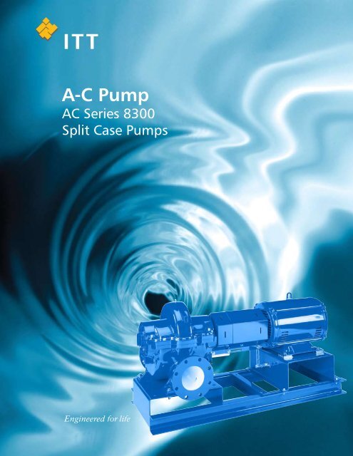
ITT<br />
A-C <strong>Pump</strong><br />
AC Series 8300<br />
Split Case <strong>Pump</strong>s
A-C <strong>Pump</strong><br />
AC Series 8300<br />
Table of conTenTs<br />
Useful <strong>Pump</strong> Formulas . . . . . . . . . . . . . . . . . . . . . . . . . . . . . . . . . . . . . . . . . . . . . . . . . . . . . . . . . . . . . . . . . . . . . . . . . . . . . . . . . . . . . . . . . . . .2<br />
Performance Curves . . . . . . . . . . . . . . . . . . . . . . . . . . . . . . . . . . . . . . . . . . . . . . . . . . . . . . . . . . . . . . . . . . . . . . . . . . . . . . . . . . . . . . . . . . . . 3-4<br />
Materials of Construction (Standard) . . . . . . . . . . . . . . . . . . . . . . . . . . . . . . . . . . . . . . . . . . . . . . . . . . . . . . . . . . . . . . . . . . . . . . . . . . . . . . . . .4<br />
L/D Ratio Comparison . . . . . . . . . . . . . . . . . . . . . . . . . . . . . . . . . . . . . . . . . . . . . . . . . . . . . . . . . . . . . . . . . . . . . . . . . . . . . . . . . . . . . . . . . . . .5<br />
Dimensions . . . . . . . . . . . . . . . . . . . . . . . . . . . . . . . . . . . . . . . . . . . . . . . . . . . . . . . . . . . . . . . . . . . . . . . . . . . . . . . . . . . . . . . . . . . . . . . . . . 6-7<br />
Engineering Specifications . . . . . . . . . . . . . . . . . . . . . . . . . . . . . . . . . . . . . . . . . . . . . . . . . . . . . . . . . . . . . . . . . . . . . . . . . . . . . . . . . . . . . . . . .8<br />
useful pump formulas<br />
Pressure (PSI) = Head (Feet) x Specific Gravity<br />
2 .31<br />
Head (Feet) = Pressure (PSI) x 2 .31<br />
Specific Gravity<br />
Vacuum = Dynamic Suction Lift (Feet) x .888 x Specific Gravity<br />
(Inches of Mercury)<br />
Horsepower (Brake) = GPM x Head (Feet) x Specific Gravity<br />
3960 x <strong>Pump</strong> Efficiency<br />
Efficiency (<strong>Pump</strong>) = Horsepower (Water) x 100%<br />
Horsepower (Brake)<br />
NPSH (Available) = Positive Factors – Negative Factors<br />
affinity laws: effect of change of speed or impeller diameter on centrifugal pumps.<br />
Impeller<br />
Diameter<br />
Change<br />
Speed<br />
Change<br />
GPM Capacity Ft . Head BHP<br />
Q2 = D2 Q1<br />
D1<br />
Q2 = RPM2 Q1<br />
2<br />
( )<br />
H 2 = D 2<br />
D 1<br />
2<br />
H1<br />
H = 2 RPM1 ( )<br />
RPM 2<br />
2<br />
RPM 1 (<br />
H1<br />
3<br />
( )<br />
P 2 = D 2<br />
D 1<br />
P1<br />
3<br />
)<br />
P 2 = RPM 2<br />
RPM 1<br />
Where Q = GPM, H = Head, P = BHP, D = Impeller Dia ., RPM = <strong>Pump</strong> Speed<br />
P1
60 cycle performance curves – ac series 8300<br />
METERS FEET<br />
200<br />
50<br />
40<br />
30<br />
20<br />
15<br />
10<br />
5<br />
4<br />
METERS FEET<br />
150 500<br />
1770 RPM<br />
400 1770 RPM<br />
100<br />
300<br />
75 250<br />
200<br />
50<br />
40<br />
150<br />
30 100<br />
80<br />
3x2x11S<br />
20<br />
60<br />
15 50<br />
40<br />
10<br />
5<br />
4<br />
30<br />
20<br />
3 10<br />
2<br />
3<br />
2<br />
150<br />
100<br />
80<br />
60<br />
50<br />
40<br />
30<br />
20<br />
10<br />
5<br />
4<br />
5<br />
50<br />
1180 RPM<br />
3x2x11L<br />
3x2x11S<br />
30<br />
6x4x12A<br />
6x4x10M<br />
3x2x11L<br />
8x6x17L<br />
6x4x14L<br />
6x4x10A<br />
150 200 300 400 500<br />
40<br />
50<br />
6x4x14L<br />
6x4x10M<br />
10x8x20S<br />
6x4x14A<br />
8x6x17L<br />
8x6x12S<br />
8x6x12L<br />
8x8x17<br />
8x6x12M<br />
8x6x17M<br />
6x4x14A<br />
6x4x12A<br />
8x6x17M<br />
10x8x20S<br />
10x8x20L<br />
10x8x17S<br />
10x8x12L<br />
6x4x10A 8x6x12S<br />
100 150 200 300 400 500 1000 1500 2000 3000 4000 5000 10000<br />
30 40 50 75 100<br />
GPM<br />
150 200 300 400 500 750 1000 1500 2000<br />
CUBIC METERS PER HOUR<br />
8x6x12XL<br />
8x6x10A<br />
8x6x13<br />
8x8x17<br />
8x6x12M<br />
8x6x12L<br />
10x8x17L<br />
10x8x12S<br />
8x6x12XL<br />
8x6x10A<br />
12x10x17<br />
12x10x12M<br />
10x8x17L<br />
10x8x12L<br />
10x8x12S<br />
12x10x14<br />
12x10x12XL<br />
10x8x17S<br />
8x6x13<br />
8x8x12<br />
10x10x12<br />
12x10x14<br />
12x10x17<br />
10x10x12<br />
1000<br />
GPM<br />
1500 2000 3000 4000 5000 10000<br />
75 100 150 200 300 400 500<br />
CUBIC METERS PER HOUR<br />
750 1000<br />
1500 2000<br />
12x10x12XL<br />
12x10x12M<br />
METERS FEET<br />
200<br />
600<br />
150 500<br />
400<br />
100<br />
75<br />
50<br />
40<br />
30<br />
20<br />
15<br />
10<br />
3<br />
300<br />
200<br />
150<br />
100<br />
80<br />
60<br />
50<br />
40<br />
3550 RPM<br />
3x2x11S<br />
3x2x11L<br />
GPM<br />
6x4x10M<br />
8x6x12M<br />
30 100 150 200 300 400 500 1000 1500 2000 3000<br />
30 40 50 75 100 150 200 300 400 500 750<br />
CUBIC METERS PER HOUR
A-C <strong>Pump</strong><br />
AC Series 8300<br />
50 cycle performance curves – ac series 8300<br />
ac series 8300 maTerials of consTrucTion<br />
Standard<br />
Mechanical<br />
Seal<br />
Mechanical Seal Mounted on shaft Part Name Material<br />
4<br />
Cast Iron, Bronze Fitted<br />
Casing assembly Cast iron (ASTM A48 Class 35A)<br />
Casing joint gasket (suction) Paper (vellumoid 505)<br />
Casing joint gasket (discharge) Paper (vellumoid 505)<br />
Casing ring Bismuth Bronze<br />
Shaft 416 Stn . Stl .<br />
Bearing housing Cast iron (ASTM A48 Class 30A)<br />
Bearing housing Cast iron (ASTM A48 Class 30A)<br />
Bearing (inboard) ball Steel<br />
Bearing (outboard) ball Steel<br />
Stuffing box (mechanical seal) Cast iron (ASTM A48 Class 30A)<br />
Lip seal (bearing) Rubber (BUNA-N)<br />
Mechanical seal Stn . stl ., rubber, carbon, ceramic<br />
Capscrew (bearing housing) Steel, grade 2<br />
Pipe plugs (bearing housing) Steel<br />
Key, impeller Stn . stl . (ANSI 416)<br />
Key, coupling Steel<br />
O-ring (casing ring) Rubber (BUNA-N)<br />
O-ring (cover plate) Rubber (BUNA-N)<br />
Retaining ring (impeller) Steel<br />
Ring retaining (bearing) Steel<br />
End cap Steel<br />
Spirol pin (casing ring) 304 SS<br />
Impeller Bronze (ASTM C87600)
l/D raTio consTrucTion<br />
The L/D ratio measures the comparable shaft stiffness<br />
factor between two pumps where “L” equals the<br />
distance between the inboard and outboard bearings<br />
and “D” represents the shaft diameter at the impeller .<br />
The lower the ratio, the stiffer the shaft . Excessive shaft<br />
5<br />
deflection will shorten mechanical seal life, subject the<br />
shaft to fatigue stress, that could result in shaft failure<br />
and increase bearing load with a corresponding reduction<br />
in bearing life . As calculated in the table below, the<br />
AC Series 8300 has a L/D ratio that is significantly below<br />
a traditional horizontal split case pump .<br />
L = Span Between D = Diameter<br />
L = Span Between D = Diameter<br />
<strong>Pump</strong> Size<br />
Bearing to Bearing (Center) Through Impeller<br />
L/D<br />
Bearing to Bearing (Center) Through Impeller<br />
3x2x11S 11 .03 1 .689 6 .5 20 .90 1 .689 12 .4<br />
3x2x11L 11 .03 1 .689 6 .5 20 .90 1 .689 12 .4<br />
6x4x10A 14 .56 1 .939 7 .5 25 .25 1 .939 13 .0<br />
6x4x10M 12 .53 1 .689 7 .4 22 .90 1 .689 13 .6<br />
6x4x12A 12 .53 1 .689 7 .4 22 .90 1 .689 13 .6<br />
6x4x14A 12 .53 1 .689 7 .4 22 .90 1 .989 13 .0<br />
6x4x14L 12 .53 1 .689 7 .4 22 .90 1 .989 13 .0<br />
8x6x10A 18 .25 1 .939 9 .4 29 .57 2 .439 12 .1<br />
8x6x12S 12 .53 1 .689 7 .4 22 .90 1 .689 13 .6<br />
8x6x12M 14 .56 1 .939 7 .5 25 .25 1 .939 13 .0<br />
8x6x12L 12 .53 1 .689 7 .4 22 .90 1 .689 13 .6<br />
8x6x12XL 12 .53 1 .689 7 .4 22 .90 1 .689 13 .6<br />
8x6x13 16 .16 1 .939 8 .3 27 .25 1 .939 14 .1<br />
8x6x17M 16 .16 1 .939 8 .3 27 .25 1 .939 14 .1<br />
8x6x17L 16 .16 1 .939 8 .3 27 .25 1 .939 14 .1<br />
8x8x12 16 .16 1 .939 8 .3 27 .25 1 .939 14 .1<br />
8x8x17 18 .59 2 .439 7 .6 29 .90 2 .439 12 .3<br />
10x8x12S 18 .59 2 .439 7 .6 29 .90 2 .439 12 .3<br />
10x8x12L 18 .59 2 .439 7 .6 29 .90 2 .439 12 .3<br />
10x8x17S 18 .59 2 .439 7 .6 29 .90 2 .439 12 .3<br />
10x8x17L 18 .59 2 .439 7 .6 29 .90 2 .439 12 .3<br />
10x8x20S 18 .59 2 .439 7 .6 29 .90 2 .439 12 .3<br />
10x8x20L 18 .59 2 .439 7 .6 29 .90 2 .439 12 .3<br />
10x10x12 21 .59 2 .439 8 .9 32 .90 2 .439 13 .5<br />
12x10x12M 21 .59 2 .439 8 .9 32 .90 2 .439 13 .5<br />
12x10x12XL 21 .59 2 .439 8 .9 32 .90 2 .439 13 .5<br />
12x10x14 18 .59 2 .439 7 .6 29 .90 2 .439 12 .3<br />
12x10x17 18 .59 2 .439 7 .6 29 .90 2 .439 12 .3<br />
L/D
A-C <strong>Pump</strong><br />
AC Series 8300<br />
ac series 8300 moDel – 150 Dimensions<br />
X YY<br />
.25" AND .50" NPT (VENT)<br />
.25" NPT<br />
BOTH<br />
NOZZLES<br />
(GAUGE)<br />
Z<br />
S<br />
S<br />
Z<br />
DISCHARGE SUCTION<br />
DISCHARGE<br />
OPTIONAL<br />
DRIP PAN<br />
YY X<br />
NOZZLES<br />
(DRAIN)<br />
HA HA<br />
LEFT HAND<br />
RIGHT HAND<br />
ROTATION VIEWED FROM PUMP END ROTATION<br />
6<br />
1 .50<br />
TYP .<br />
4" REMOVAL<br />
CLEARANCE<br />
HO<br />
VH<br />
HD<br />
.75 NPT<br />
(DRAIN)<br />
STaNDarD: 125# FF aNSI FLaNge (aNSI a21.10, aWWa C110 & aNSI B16.1 class 125)<br />
MoTor DIMeNSIoNS – INCheS (MM)<br />
PuMP SIze FraMe ha hB hP hr CP hC* MaX hD ho S & z Vh Vh1 W X YY<br />
3x2x11 143-215 20 .00 44 .00 (1118) 6 .00 2 .25 18 .62 39 (991)<br />
15 .25 (388) 22 .05 (560)<br />
5 .50 6 .80<br />
– 11 .31 9 .00 10 .00<br />
S, L 254-365 (508) 54 .00 (1372) (152) (57) (473) 50 (1270) (140) (173) (287) (229) (254)<br />
6x4x10A<br />
182-215 21 .50 48 .00 (1219) 6 .00 2 .88 19 .93 50 (1270)<br />
18 .25 (464) 25 .94 (659)<br />
7 .00 7 .69<br />
– 12 .19 11 .50 12 .00<br />
254-324 (546) 54 .00 (1372) (152) (73) (506) 59 (1499) (178) (195) (310) (292) (305)<br />
182-215 48 .00 (1219) 43 (1092)<br />
254-326 24 .00 58 .00 (1473)<br />
6x4x10M<br />
6 .00 4 .62 22 .81 52 (1321) 18 .25 (464) 26 .12 (664) 6 .50 7 .88<br />
– 13 .50 11 .50 13 .00<br />
364-405 (610) 64 .00 (1626) (152) (117) (579) 61 (1549) (165) (200) (343) (292) (330)<br />
444-445 76 .00 (1930) 68 (1727) 20 .25 (514) 28 .12 (714)<br />
6x4x12A<br />
215 48 .00 (1219)<br />
254-326<br />
43 (1092)<br />
24 .00 58 .00 (1473) 6 .00 4 .62 22 .81 (610)<br />
364-365 64 .00 (1626)<br />
(152) (117) (579)<br />
52 (1321)<br />
61 (1549)<br />
18 .25 (464) 26 .81 (681)<br />
738<br />
(188)<br />
8 .56<br />
(218)<br />
–<br />
13 .50<br />
(343)<br />
11 .50<br />
(292)<br />
13 .00<br />
(330)<br />
215-256 48 .00 (1219) 45 (1143)<br />
6x4x14A<br />
284-365 24 .00 58 .00 (1473) 6 .00 3 .25 20 .62 54 (1372) 19 .52 (489) 28 .50 (723) 7 .75 9 .20<br />
– 12 .56 11 .50 13 .00<br />
404-405 (610) 68 .00 (1727) (152) (83) (524) 60 (1524) (197) (234) (319) (292) (330)<br />
444 76 .00 (1930) 64 (1625) 21 .52 (547) 35 .00 (889)<br />
6x4x14L<br />
182-256 24 .00 48 .00 (1219) 6 .00 3 .25 20 .62 45 (1143)<br />
19 .25 (489) 28 .87 (733)<br />
7 .75 9 .62<br />
– 12 .56 11 .50 13 .00<br />
284-365 (610) 58 .00 (1473) (152) (83) (524) 54 (1372) (197) (244) (319) (292) (330)<br />
8x6x10A<br />
215-286 58 .00 (1473)<br />
324-326<br />
56 .38 (1432)<br />
24 .00 64 .00 (1626) 6 .00 10 .75 29 .19 58 .38 (1438) 21 .25 (540) 30 .50 (775)<br />
8 .25 9 .25<br />
– 17 .58 12 .50 12 .50<br />
(610)<br />
364-365 68 .00 (1727)<br />
(152) (273) (741)<br />
60 .38 (1534)<br />
(210) (235) (447) (328) (318)<br />
8x6x12<br />
S, L, XL<br />
182-256 48 .00 (1219)<br />
284-326<br />
45 (1143)<br />
21 .50 54 .00 (1372) 6 .00 3 .25 20 .62 51 (1295) 21 .25 (540) 28 .75 (730)<br />
9 .00 9 .60<br />
– 12 .56 14 .00 14 .00<br />
(546)<br />
364-365 60 .00 (1524)<br />
(152) (83) (524)<br />
54 (1372)<br />
(229) (244) (319) (356) (356)<br />
254-326 58 .00 (1473)<br />
8x6x12M 364-405<br />
53 (1346)<br />
21 .25 (540) 30 .85 (784)<br />
24 .00 64 .00 (1626) 6 .00 4 .63 22 .81 61 (1549)<br />
9 .00 9 .60<br />
– 13 .50 14 .00 14 .00<br />
(610)<br />
444-447 76 .00 (1930)<br />
(152) (118) (579)<br />
71 (1803) 23 .25 (591) 32 .85 (835)<br />
(229) (244) (343) (356) (356)<br />
8x6x13<br />
254-326 24 .00 62 .00 (1575) 6 .00 5 .63 26 .19 56 (1422)<br />
20 .00 (508) 29 .40 (747)<br />
8 .00 9 .40<br />
– 16 .06 13 .00 15 .50<br />
364-405 (610) 68 .00 (1727) (152) (143) (665) 65 (1651) (203) (239) (408) (330) (394)<br />
8x6x17<br />
M, L<br />
284-326 62 .00 (1575)<br />
364-405<br />
56 (1442)<br />
24 .00 68 .00 (1727) 6 .00 5 .63 26 .19 65 (1651) 21 .25 (540) 33 .00 (838)<br />
9 .00 11 .75<br />
– 16 .06 14 .00 16 .00<br />
(610)<br />
444-445 76 .00 (1930)<br />
(152) (143) (665)<br />
71 (1803)<br />
(229) (299) (408) (356) (406)<br />
8x8x12<br />
254-326 24 .00 62 .00 (1575) 6 .00 5 .63 26 .19 56 (1422)<br />
20 .00 (508) 30 .25 (768)<br />
8 .00 10 .25<br />
– 16 .06 14 .00 16 .50<br />
364-405 (610) 68 .00 (1727) (152) (143) (665) 65 (1651) (203) (260) (408) (356) (419)<br />
8x8x17<br />
324-365 66 .00 (1676)<br />
404-445<br />
62 (1575) 21 .75 (553) 33 .75 (857)<br />
24 .00 76 .00 (1930) 6 .00 7 .00 28 .94 74 (1880)<br />
23 .75 (603) 35 .75 (908)<br />
9 .50 12 .00<br />
– 17 .56 15 .00 16 .50<br />
(610)<br />
447-449 86 .00 (2184)<br />
(152) (178) (735)<br />
82 (2083)<br />
(241) (305) (446) (381) (419)<br />
10x8x12<br />
S, L<br />
254-286 62 .00 (1575) 56 (1422)<br />
21 .50 (546) 32 .00 (813)<br />
324-365 24 .00 66 .00 (1676) 6 .00 7 .00 28 .94 62 (1575)<br />
8 .50 10 .50<br />
– 17 .56 14 .00 17 .00<br />
(610)<br />
404-445 76 .00 (1930)<br />
(152) (178) (735)<br />
74 (1880) 23 .50 (597) 34 .00 (864)<br />
(216) (267) (446) (356) (432)<br />
Not for construction unless certified.<br />
4 .00<br />
HP<br />
HR<br />
CP<br />
W<br />
HC*<br />
HB<br />
.50 MIN
STaNDarD: 125# FF aNSI FLaNge (aNSI a21.10, aWWa C110 & aNSI B16.1 class 125) CoNTINueD<br />
MoTor DIMeNSIoNS – INCheS (MM)<br />
PuMP SIze FraMe ha hB hP hr CP hC* MaX hD ho S & z Vh Vh1 W X YY<br />
10x8x17<br />
S, L<br />
324-365 66 .00 (1676) 62 (1575) 23 .25 (591) 36 .06 (916)<br />
404-445 24 .00 76 .00 (1930) 6 .00 7 .00 28 .94 74 (1880)<br />
25 .25 (641) 38 .06 (967)<br />
10 .00 12 .81<br />
– 17 .56 16 .00 18 .00<br />
(610)<br />
447-449 86 .00 (2184)<br />
(152) (178) (735)<br />
82 (2083)<br />
(254) (325) (446) (406) (457)<br />
10x8x20<br />
S, L<br />
324-365 66 .00 (1676) 62 (1575) 27 .25 (692) 49 .50 (1257)<br />
404-445 26 .00 76 .00 (1930) 6 .00 7 .00 28 .94 (660)<br />
447-449 86 .00 (2184)<br />
(152) (178) (735)<br />
74 (1880)<br />
82 (2083)<br />
29 .25 (743)<br />
14 .00 15 .44 22 .25 17 .56<br />
51 .50 (1308) (356) (392) (565) (446)<br />
18 .00<br />
(457)<br />
20 .00<br />
(508)<br />
284-365 24 .00 68 .00 (1727)<br />
12x10x12<br />
6 .00 8 .50 31 .94 68 (1727) 22 .50 (572) 33 .69 (856) 9 .00 11 .19<br />
– 19 .06 16 .00 18 .00<br />
404-445 (610) 80 .00 (2032) (152) (216) (811) 81 (2057) 24 .50 (622) 35 .69 (907) (229) (284) (484) (406) (457)<br />
12x10x12 284-365 24 .00 68 .00 (1727) 6 .00 8 .50 31 .94 68 (1727) 24 .50 (622) 36 .00 (914) 10 .00 11 .50<br />
– 19 .06 16 .00 19 .00<br />
M, XL 404-445 (610) 80 .00 (2032) (152) (216) (811) 81 (2057) 26 .50 (673) 38 .00 (965) (254) (292) (484) (406) (483)<br />
324-365 66 .00 (1676)<br />
12x10x14 404-445<br />
62 (1575) 25 .25 (641) 38 .69 (983)<br />
24 .00 76 .00 (1930) 6 .00 7 .00 28 .94 74 (1880)<br />
27 .25 (692)<br />
11 .00 13 .44<br />
40 .69 (1034)<br />
– 17 .56 18 .00 20 .00<br />
(610)<br />
447-449 86 .00 (2184)<br />
(152) (178) (735)<br />
82 (2083)<br />
(280) (341) (446) (457) (508)<br />
324-365 66 .00 (1676)<br />
12x10x17 404-445<br />
62 (1575) 25 .25 (641) 38 .69 (983)<br />
24 .00 76 .00 (1930) 6 .00 7 .00 28 .94 74 (1880)<br />
27 .25 (692)<br />
11 .00 13 .44<br />
40 .69 (1034)<br />
– 17 .56 18 .00 20 .00<br />
(610)<br />
447-449 86 .00 (2184)<br />
Not for construction unless certified.<br />
(152) (178) (735)<br />
82 (2083)<br />
(280) (341) (446) (457) (508)<br />
mechanical seal DaTa<br />
Standard Construction<br />
• 175 PSIG (12 BAR) maximum working pressure<br />
• *100 PSIG (7 BAR) maximum suction pressure<br />
125#FF ANSI flange (ANSI A21 .10, AWWA C110 &<br />
ANSI B16 .1 class 125)<br />
• Type 21, BUNA/Carbon-ceramic, *100 PSIG (7 BAR)<br />
maximum suction pressure, from -20º to 225ºF (-29º<br />
to 107ºC)<br />
• Optional seals:<br />
• Type 21, EPR/carbon-ceramic, *100 PSIG (7 BAR)<br />
maximum suction pressure, from -20º to 250ºF<br />
(-29º to 121ºC)<br />
• Type 21, EPR/carbon-tungsten carbide, *100 PSIG<br />
(7 BAR) maximum suction pressure, from -20º to<br />
250ºF (-29º to 121ºC)<br />
* Maximum suction pressure for 3500 RPM is<br />
85 PSIG (6 BAR) .<br />
Internally Self-Flushing Seal:<br />
The AC Series 8300 features internally self-flushing<br />
mechanical seals . This innovative design, and industry<br />
standard, insures maximum seal life lubrication, heat<br />
dissipation and debris removal – all without vulnerable,<br />
external flush lines and filter kits that can clog and result<br />
in seal failure . With the A-C <strong>Pump</strong> internally self-flushing<br />
seal design, as much as 25% of the total pump flow<br />
continuously flushes the seal faces compared to only a<br />
few GPM for conventional stuffing box mounted mechanical<br />
seals . Seals remain cooler and unwanted debris<br />
is flushed away from the mechanical seal faces resulting<br />
in longer mechanical seal life .<br />
7
engineering specificaTion for ac series 8300 base mounTeD Double sucTion pumps<br />
Double Suction, horizontal Split Case <strong>Pump</strong>s (Base Mounted):<br />
a. Manufacturer:<br />
Contractor shall furnish and install new double suction horizontal split<br />
case pumps for water transport and boosting applications as indicated on<br />
the drawings . <strong>Pump</strong>s shall be the AC Series 8300 as manufactured by A-C<br />
<strong>Pump</strong> under base bid . <strong>Pump</strong>s shall meet types, sizes, capacities and characteristics<br />
as scheduled on the Equipment Schedule drawings .<br />
B. Double Suction horizontal Split Case <strong>Pump</strong> (Base Mounted):<br />
1 . The pumps shall be long coupled, base mounted, single<br />
stage, double suction, horizontally split case design, in cast<br />
iron bronze fitted construction specifically designed and<br />
guaranteed for quiet operation . Suitable standard operations<br />
at 225ºF and 175 PSIG working pressure . Working pressures<br />
shall not be de-rated at temperatures up to 250ºF . The pump<br />
internals shall be capable of being serviced without disturbing<br />
the upper casing half and system piping .<br />
2. A bearing housing shall supply support for a pair of heavy-<br />
duty regreasable ball bearings . An inboard single row bearing<br />
will absorb thermal expansive forces while an outboard<br />
double row bearing will be clamped in place to absorb both<br />
radial and thrust loads and keep the rotating element in<br />
proper axial alignment . Bearings shall be replaceable without<br />
disturbing the system piping, the upper casing half, and shall<br />
be regreasable without removal of the bearings from the<br />
bearing housing .<br />
3. The impeller shaft shell be a solid 416 stainless steel shaft .<br />
4. <strong>Pump</strong> shall be equipped with a pair of internally flushed<br />
mechanical seal assemblies in direct contact with the pump<br />
shaft . Seal assemblies shall be Type 21 having a stainless steel<br />
housing, BUNA bellows and seat gasket, stainless steel<br />
spring, and be of carbon-ceramic design with the carbon face<br />
rotating against a stationary ceramic face .<br />
5. Impeller shall be of the enclosed double suction type made of<br />
ASTM B584-876 bronze, both hydraulically and dynamically<br />
balanced to ANSI/HI 1 .1-1 .5-1994, section 1 .4 .6 .1 .3 .1, figure<br />
1 .106, balance grade G6 .3 keyed to the shaft and fixed in the<br />
axial position .<br />
6. A flexible type coupling, capable of absorbing torsional<br />
vibration, shall be employed between the pump and motor . On<br />
variable speed applications the coupler sleeve should be<br />
constructed of an SPDM material to maximize performance life .<br />
7. The coupling shall be shielded by a dual rated ANSI B15 .1,<br />
Section 8 and OSHA 1910 .219 compliant coupling guard and<br />
contain viewing windows for inspection of the coupling .<br />
8. <strong>Pump</strong> volute shall be of a cast iron (rated for 175 PSIG max .<br />
WP) axially-split design with flanges (175 PSIG drilled for<br />
125# ANSI companion flanges) and mounting feet integral<br />
www.acpump.com<br />
Copyright (c) 2008 ITT Corporation BRAC8300 October, 2008 Printed in U.S.A.<br />
SPECIFICATIONS ARE SUBJECT TO CHANGE WITHOUT NOTICE.<br />
cast into the bottom half of the casing . Suction and discharge<br />
flanges shall be on a common centerline in both the<br />
horizontal and vertical planes, and the volute shall include<br />
bronze casing wear rings, priming port, gauge ports at<br />
nozzles, and vent and drain ports . The upper half casing shall<br />
be capable of being removed without disturbing piping<br />
connections or electrical motor connections .<br />
9. <strong>Pump</strong> seal flushing shall be internal within the pump casing<br />
and shall flush the seal at a rate equal to 25% of the total<br />
pump flow .<br />
10. Motors shall meet scheduled horsepower, speed, voltage and<br />
enclosure design . <strong>Pump</strong> and motors shall be factory<br />
aligned, and shall be realigned after installation by the<br />
manufacturer‘s representative . Motors shall be<br />
non-overloading at any point on the pump curve and shall<br />
meet NEMA specifications and conform to the standards<br />
outlined in EPACT 92 .<br />
11. Base plate shall be of structural steel or fabricated steel<br />
channel with fully enclosed sides and ends, and securely<br />
welded cross members . The grouting area shall be fully open .<br />
The combined pump and motor base plate shall be sufficiently<br />
stiff as to limit the susceptibility of bibration . The minimum<br />
base plate stiffness shall conform to ANSI/HI 1 .3 .4-1997 for<br />
Horizontal Baseplate Design standards .<br />
12. Base shall be capable of being field grouted .<br />
13. <strong>Pump</strong> rotation shall be righthand or lefthand as viewed from<br />
the pump end .<br />
14. <strong>Pump</strong> manufacturer shall be ISO9001 certified .<br />
15. The seismic capability of the pump shall allow it to withstand<br />
a horizontal load of 0 .5g, excluding piping and/or fasteners<br />
used to anchor the pump to mounting pads or to the floor,<br />
without adversely affecting pump operation .<br />
16. Each pump shall be factory hydrostatically tested per<br />
Hydraulic Institute standards and name-plated before<br />
shipment . It shall then be thoroughly cleaned and painted<br />
with at least one coat of high grade paint prior to shipment .<br />
C. accessories:<br />
1. Where noted on schedule pumps shall be provided with<br />
internal bronze pump wear rings, special shaft materials,<br />
or special spacer couplers .<br />
2. Where noted on schedule either balanced or unbalanced seals<br />
of EPR carbon/ceramic seals, EPR tungsten/carbide seal, or<br />
packing gland material should be used in lieu of the standard<br />
seal .<br />
3. Where noted on schedule pumping equipment may require<br />
one or all of the following tests: certified lab tests<br />
(unwitnessed), Hydraulic Institute Level B tests,<br />
or witnessed tests .<br />
8<br />
ITT<br />
Engineered for life


