
Create successful ePaper yourself
Turn your PDF publications into a flip-book with our unique Google optimized e-Paper software.
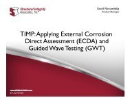
Corrosion<br />
&<br />
Cathodic Protection<br />
Presented by<br />
Marty Iozzo
Cost of Corrosion<br />
NACE International & U.S. Federal Highway Administration ‐ 2002
Cost of Corrosion<br />
$276,000,000,000!<br />
Each Year!!
…..So What is Corrosion?
…..So What is Corrosion?<br />
2Fe + O₂ + 2H₂O → 2Fe⁺⁺ + 4OH‐<br />
What?????
‐ OR ‐<br />
• An Electro‐Chemical Reaction of a Metal With<br />
Its Environment<br />
• The Tendency of a Metal to Return to Its<br />
Origin
Corrosion<br />
Four parts needed for a corrosion cell to exist<br />
1. Anode – Where corrosion occurs<br />
2. Cathode – Protected from corrosion<br />
3. Electrolyte ‐ Soil or water (any conductive<br />
environment) adjacent to –and containing<br />
both the anode and the cathode<br />
4. Metallic Path ‐ Physically connects the<br />
anode to the cathode<br />
*Remove any one part, and the corrosion cell cannot exist
Galvanic<br />
Series
Typical Corrosion Cell
Corrosion Cell ‐ Battery
Galvanic<br />
Series<br />
Metal Higher (more<br />
negative) on the scale is<br />
the Anode
Corrosion Cell ‐ Galvanic Anode
Galvanic<br />
Series<br />
Metal Higher is Anode
New Pipe/Old Pipe
Galvanic<br />
Series<br />
Metal Higher is Anode
Dissimilar Metals
Galvanic<br />
Series<br />
Metal Higher is Anode
Dissimilar Metals
Galvanic<br />
Series<br />
Metal Higher is Anode
Bright Metal
Galvanic<br />
Series<br />
Metal Higher is Anode
Dissimilar Soils
Dissimilar Soils<br />
Pipeline in Clay is Anodic<br />
Adjacent Pipeline in Sand is Cathodic
Differential Oxygen
Differential Oxygen<br />
Pipeline Under a Roadway<br />
Pipeline Under a Railroad<br />
Pipeline Under a Water Crossing
Stress Corrosion
Stress Corrosion<br />
Stress Concentration on Bolts<br />
Bolts in Tension
CP Interference Corrosion
AC Induction
Corrosion Prevention<br />
&<br />
Corrosion Control<br />
(Cathodic Protection)
How Cathodic Protection Works<br />
As previously mentioned, corrosion occurs<br />
where DC current discharges from the<br />
structure to the electrolyte at the anode<br />
The objective is to allow the entire structure<br />
to be cathodic
How Cathodic Protection Works<br />
As the potential of the cathode sites polarize<br />
towards the potential of the anode sites,<br />
corrosion is reduced.<br />
When the potential of all cathode sites reach<br />
the open circuit potential of the most active<br />
anode site, corrosion is eliminated.
Polarization Reduces the ΔV Along<br />
the Structure
Corrosion<br />
Four parts needed for a corrosion cell to exist<br />
1. Anode – Where corrosion occurs<br />
2. Cathode – Protected from corrosion<br />
3. Electrolyte ‐ Soil or water (any conductive<br />
environment) adjacent to –and containing<br />
both the anode and the cathode<br />
4. Metallic Path ‐ Physically connects the<br />
anode to the cathode<br />
*Remove any one part, and the corrosion cell cannot exist
Cathodic Protection<br />
Four parts needed for a CP cell to exist<br />
1. Anode – Where corrosion occurs<br />
2. Cathode – Protected from corrosion<br />
3. Electrolyte ‐ Soil or water (any conductive<br />
environment) adjacent to –and containing<br />
both the anode and the cathode<br />
4. Metallic Path ‐ Physically connects the<br />
anode to the cathode<br />
*Remove any one part, and Cathodic Protection cannot exist
CP Cell ‐ Battery
Cathodic Protection<br />
• Galvanic Anode<br />
• Impressed Current
Galvanic Anode<br />
• Requires No External Power<br />
• Smaller Diameter Pipe<br />
• Coated Structure<br />
• Isolated Structure<br />
• Lesser Current Requirements<br />
• Lesser Concern For Interference
Coatings<br />
• Fusion Bonded Epoxy (FBE)<br />
• Two Part Liquid Epoxy<br />
• Polyethylene & Polypropylene<br />
• Coal Tar Enamel<br />
• Wax<br />
• Mastic<br />
• Shrink Sleeve<br />
• Tape (Hot & Cold Applied)
Galvanic Anode
Galvanic<br />
Series<br />
Metal Higher is Anode
Galvanic CP Design
Impressed Current<br />
• Requires External Power<br />
• Lots of Current Needed<br />
• Poorly Coated or Bare<br />
• Electrical Isolation Not Possible<br />
• Larger Diameter Pipe<br />
• Buried Tanks & Tank Bottoms<br />
• Long Lines<br />
• More Chance For Interference
Impressed Current
Impressed Current
Impressed<br />
Current
Interference Bond
When Is Cathodic Protection<br />
Achieved?<br />
When we can compare our measured<br />
cathodic protection potentials against,<br />
and satisfy a recognized Standard<br />
Recommended <strong>Practice</strong> ‐ while making<br />
considerations for ‘IR Drop / Error’
+<br />
0.000<br />
CLEAN<br />
WATER<br />
C.P. TEST EQUIPMENT<br />
HIGH INPUT IMPEDANCE DIGITAL VOLT METER<br />
10 M OR GREATER<br />
COPPER/COPPER SULFATE REFERENCE CELL<br />
CLEAN, FULLY CHARGED & CALIBRATED<br />
TEST WIRES WITH ALLIGATOR CLIPS<br />
SELECTION OF SHORT & LONG WITH NO SPLICES<br />
CLEAN WATER<br />
TO SATURATE THE TEST LOCATION<br />
MISC. HAND TOOLS<br />
TO MAKE MINOR REPAIRS ON-SITE
The ‘Weakest Link’
IR Drop / Error ‐ Defined<br />
IR Drop is primarily caused by CP current<br />
flowing through some resistance<br />
IR Drop is higher when current is large<br />
IR Drop is higher when Resistance is large<br />
IR Drop is higher on well‐coated structures<br />
when the distance to the nearest coating<br />
holiday is greater (longer DC path)
Structure‐to‐Soil Potential<br />
Measurement
‐0.85V Current Applied Criterion w/IR<br />
Drop Considered<br />
The reference cell is placed as close as possible to the<br />
structure under test (near structure)<br />
A structure‐to‐soil potential is read and recorded<br />
The reference cell is placed at ‘remote earth’ from the<br />
structure<br />
A structure ‐to‐soil potential is read and recorded<br />
Subtract the difference in potential readings from the<br />
‘near structure’ potential to obtain ‘IR Drop Free’<br />
potential<br />
This potential must be at least ‐0.85V to meet criterion
‐0.85V Polarized Criterion<br />
(No DC Current Flow)<br />
Interrupt ALL sources of DC current flow<br />
All influencing rectifiers<br />
Bonds to foreign structures<br />
Sacrificial anodes my not be practical<br />
Interruption must be done quickly and simultaneously<br />
The reference cell is placed as close as possible to the<br />
structure under test<br />
Read and record the ‘OFF Cycle’ potential (Instant Off)<br />
The ‘OFF Cycle’ potential must be at least ‐0.85V to meet<br />
criteria
100mV Polarization (Decay) Criterion<br />
Interrupt ALL sources of DC current flow<br />
All influencing rectifiers<br />
Bonds to foreign structures<br />
Sacrificial anodes my not be practical<br />
Interruption must be done quickly and simultaneously<br />
Record ‘ON Cycle’ potential<br />
Record ‘OFF Cycle’ potential<br />
Turn off all sources of DC current flow<br />
Allow the Structure to ‘Depolarize’<br />
There must be at least 100mV potential decay from the ‘OFF<br />
Cycle’ potential to the ‘Depolarized’ potential to meet<br />
criteria
100mV Polarization (Formation)<br />
Criterion<br />
Remove ALL sources of DC current flow and allow<br />
the structure to completely depolarize<br />
Record the depolarized baseline<br />
Energize the structure and record the ON potential<br />
Interrupt ALL sources of DC current and record the<br />
OFF potential (Instant Off)<br />
Allow the structure to polarize<br />
There must be at least 100mV of potential<br />
formation from the depolarized baseline to the OFF<br />
potential to meet criteria
Common C.P. Measurement Errors<br />
Faulty Test Equipment<br />
All test equipment should be in proper working condition. The voltmeter should be calibrated or “known” to be accurate. All<br />
test leads and jumper wires should be checked for continuity before each use.<br />
Reference Cell Condition<br />
The reference cell should be clean, fully charged and calibrated.<br />
Poor Structure Connection<br />
Make sure contact is being made with the structure under test.<br />
Reference Cell Placement<br />
The reference cell should be placed as near as possible (without touching) the structure under test. The reference cell should<br />
be positioned over native soil only. Never attempt to measure through concrete, asphalt, etc.<br />
Soil Condition<br />
Saturate the soil around the test location with clean water if dry conditions are encountered. Avoid Contaminated soil.<br />
IR (Voltage) Drop (Error)<br />
See all conditions listed above.<br />
Outside Air Temperature<br />
The reference cell is stable and calibrated at an ambient temperature of 70 degrees F. The reference cell will have a potential<br />
difference of 0.5mV per 1 degree F from ambient temperature.<br />
Inclement Weather<br />
Never conduct potential measurements during severe weather conditions. Also, saturated/conductive equipment and<br />
personnel will lead to erroneous potential readings.<br />
Experience
So……. To Summarize<br />
Corrosion is the degradation of steel due to a<br />
reaction with its environment<br />
Cathodic Protection is achieved when the cathodic<br />
sites of a structure are polarized in the direction to<br />
the potential of the most anodic sites on the same<br />
structure<br />
Cathodic Protection can be ‘proved’ by following<br />
recommended practices to meet criteria