a trichromatic colorimeter with spectral primaries - InfoCom
a trichromatic colorimeter with spectral primaries - InfoCom
a trichromatic colorimeter with spectral primaries - InfoCom

You also want an ePaper? Increase the reach of your titles
YUMPU automatically turns print PDFs into web optimized ePapers that Google loves.
228 W. D. Wright<br />
It will be readily realised that to use the system as it has been developed SO<br />
far some difficulty would be experienced in separating the reflected from the<br />
incident beam. Both would traverse the same parts of the prism and objective<br />
and it would be necessary to introduce a parallel plate of glass, possibly half silvered,<br />
into the path of the beams. By inclining this plate at 45" to the direction of the<br />
returning beam, this light would be partially reflected and a separation of the two<br />
beams would be effected. This method would, however, lead to a great loss of light<br />
and, in addition, the surface reflections from the prism faces and the telescope<br />
objective would be mixed up <strong>with</strong> the returning beam, thus introducing stray light.<br />
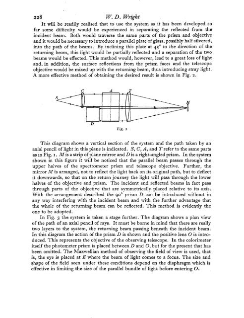
A more effective method of obtaining the desired result is shown in Fig. 2.<br />
C A T<br />
D<br />
Fig. 2<br />
This diagram shows a vertical section of the system and the path taken by an<br />
axial pencil of light in this plane is indicated. S, C, A, and T refer to the same parts<br />
as in Fig. I. M is a strip of plane mirror and D is a right-angled prism. In the system<br />
shown in this figure it will be noticed that the parallel beam passes through the<br />
upper halves of the spectrometer prism and telescope objective. Further, the<br />
mirror M is arranged, not to reflect the light back on its original path, but to deflect<br />
it downwards, so that on the return journey the light will pass through the lower<br />
halves of the objective and prism. The incident and reflected beams in fact pass<br />
through parts of the objective that are symmetrically placed relative to its axis.<br />
With the arrangement described the 90' prism D can be introduced <strong>with</strong>out in<br />
any way interfering <strong>with</strong> the incident beam and <strong>with</strong> the further advantage that<br />
the whole of the returning beam can be reflected. This method is evidently the<br />
one to be adopted.<br />
In Fig. 3 the system is taken a stage further. The diagram shows a plan view<br />
of the path of an axial pencil of rays. It must be borne in mind that there are really<br />
two layers to the system, the returning beam passing beneath the incident beam.<br />
In this diagram the action of the prism D is shown and the positive lens 0 is intro-<br />
duced. This represents the objective of the observing telescope. In the <strong>colorimeter</strong><br />
itself the photometer prism is placed between D and 0, but for the present that has<br />
been omitted. The Maxwellian method of observing the field of view is used, that<br />
is, the eye is placed at E where the beam of light comes to a focus. The size and<br />
shape of the field seen under these conditions depend on the diaphragm which is<br />
effective in limiting the size of the parallel bundle of light before entering 0.