Wireless Mesh Best Practice Guide
Wireless Mesh Best Practice Guide
Wireless Mesh Best Practice Guide

Create successful ePaper yourself
Turn your PDF publications into a flip-book with our unique Google optimized e-Paper software.
B E S T P R A C T I C E G U I D E<br />
<strong>Wireless</strong> <strong>Mesh</strong><br />
This document was developed as a best practice guide for<br />
Ruckus Smart <strong>Mesh</strong> Networking installations. It includes<br />
real-world deployments and suggestions on coverage,<br />
capacity, technology choice (802.11n versus 802.11g), and<br />
other topics — to aid in the optimum reliability and performance<br />
of a Smart <strong>Mesh</strong> Network infrastructure.<br />
Introduction<br />
A wireless mesh network is a peer-to-peer, multi-hop wireless<br />
network in which participant nodes or access points<br />
cooperate to route packets.<br />
Indoor wireless networking, while not a new concept, has<br />
always been an attractive option for enterprises interested<br />
more cost-effectively building or extending wireless LANs<br />
to areas where Ethernet cabling does not existing or is cost<br />
prohibitive.<br />
However indoor wireless mesh networking has largely floundered<br />
within the enterprise due to the inability of Wi-Fi systems<br />
to provide reliable and adaptive connections through<br />
the RF domain which effectively serves as the network<br />
backbone within a wireless mesh infrastructure.<br />
Recent technical advances in the area of smart antenna<br />
arrays and RF signal path control overcome these issues —<br />
providing the ability to construct a reliable wireless mesh<br />
backbone that delivers consistent system-wide performance<br />
by constantly steering signal over the best paths thereby<br />
ensuring that the best connections between intermediate<br />
nodes are used. These advances have become known as<br />
“Smart <strong>Mesh</strong> Networking.”<br />
Smart <strong>Mesh</strong> networks are therefore different from traditional<br />
mesh networks in two fundamental aspects: 1) their ability to<br />
automatically adapt link layer wireless connections between<br />
mesh nodes by routing over the best signal path at any given<br />
time to reduce packet loss and 2) the ability to minimize<br />
mesh hops through the use of high-gain, directional “smart”<br />
antennas. This allows mesh nodes to be placed farther apart,<br />
reducing the number of hops required to cover a given area<br />
as well as reducing the capital and operational costs associated<br />
with constructing a conventional indoor wireless mesh<br />
network. In a Ruckus Smart <strong>Mesh</strong> Network, the routing nodes<br />
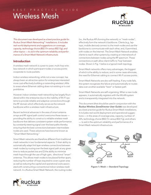
(i.e., the Ruckus APs forming the network), or “mesh nodes”,<br />
effectively form the network’s backbone. Clients (e.g., laptops,<br />
mobile devices) connect to the mesh nodes and use the<br />
backbone to communicate with each other, and, if permitted,<br />
with nodes on the Internet. The Smart <strong>Mesh</strong> Network enables<br />
clients to reach other systems by creating an internetwork of<br />
connections between nodes using the RF spectrum. These<br />
connections or path allow client traffic to ‘hop’ between<br />
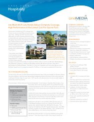
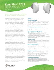
nodes. Shown in Fig. 1 below is a typical mesh topology.<br />
Smart <strong>Mesh</strong> networks offers many advantages, the biggest<br />
of which is the ability to reduce, and in some cases eliminate,<br />
the need for Ethernet cabling to connect Wi-Fi access points.<br />
Smart <strong>Mesh</strong> Networks are also self-healing. If any node fails,<br />
the system recognizes the failure and automatically re-routes<br />
data over another available “best” or fastest path<br />
Smart <strong>Mesh</strong> Networks are self-organizing. When a new node<br />
appears, it automatically registers with the WLAN system<br />
and is transparently integrated into the network.<br />
This document (that should be used in conjunction with the<br />
Ruckus <strong>Wireless</strong> ZoneDirector User <strong>Guide</strong>) was developed<br />
as a best practice guide for Ruckus Smart <strong>Mesh</strong> installations.<br />
It includes real-world deployment and operational suggestions<br />
— in the areas of coverage area, capacity, number of<br />
APs, technology choice (802.11n versus 802.11g), and others<br />
— to aid in the optimum reliability and performance of a<br />
Smart <strong>Mesh</strong> network infrastructure.<br />
<strong>Mesh</strong> AP<br />
Root AP Root AP<br />
<strong>Mesh</strong> AP <strong>Mesh</strong> AP <strong>Mesh</strong> AP<br />
Figure 1: <strong>Mesh</strong> — Standard Topology
<strong>Wireless</strong> <strong>Mesh</strong> <strong>Best</strong> <strong>Practice</strong> <strong>Guide</strong><br />
<strong>Mesh</strong> Networking Terms<br />
Term Definition<br />
<strong>Mesh</strong> Node A Ruckus ZoneFlex AP with mesh capability<br />
enabled. Ruckus ZoneFlex models that<br />
provide mesh capability include: ZoneFlex<br />
7962 (indoor, dual-band 802.11n), ZoneFlex<br />
7762 (outdoor, dual-band 802.11n), ZoneFlex<br />
2942 (indoor 802.11g), ZoneFlex 2741 (outdoor<br />
802.11g), and the Ruckus ZoneFlex 2925 desktop<br />
model.<br />
Root Access Point<br />
(Root AP, or RAP)<br />
<strong>Mesh</strong> Access Point<br />
(<strong>Mesh</strong> AP, or MAP)<br />
A ZoneFlex AP physically wired to the L2/L3<br />
network, acting as the entry point to the local<br />
area network.<br />
A Wi-Fi access point that has no physical<br />
Ethernet connection, acting as a mesh node<br />
communicating to a ZoneDirector through its<br />
wireless interface.<br />
<strong>Mesh</strong> Tree The internetwork of mesh nodes and root APs<br />
forming the wireless LAN.<br />
Each <strong>Mesh</strong> AP has exactly one uplink to another<br />
<strong>Mesh</strong> AP or Root AP. Each <strong>Mesh</strong> AP or Root<br />
AP could have multiple <strong>Mesh</strong> APs connecting<br />
to it. Thus, the resulting topology is a tree-like<br />
topology. The maximum allowed depth of a<br />
mesh tree is 8, although best practice depth is<br />
typically smaller at outlined in this document.<br />
A ZoneDirector can manage more than one<br />
mesh tree. The only limitation of how many<br />
mesh trees it can manage is dependent on the<br />
number of APs a ZoneDirector can manage. For<br />
example, a ZD1006 can manage a mesh tree of 6<br />
APs or two mesh trees of 3 APs each.<br />
Hop The transit of a data packet through a mesh<br />
access point or node. The “hop count” for a<br />
given client’s data traffic is typically defined<br />
by the number of wireless mesh links a data<br />
packet travels from one <strong>Mesh</strong> AP to the Root<br />
AP.<br />
For example, if the Root AP is the uplink of<br />
<strong>Mesh</strong> AP 1, then <strong>Mesh</strong> AP 1 is one hop away<br />
from the Root AP. In the same scenario, if<br />
<strong>Mesh</strong> AP 1 is the uplink of <strong>Mesh</strong> AP 2, then<br />
<strong>Mesh</strong> AP 2 is two hops away from the Root AP.<br />
Supported <strong>Mesh</strong> Topologies<br />
Standard Topology<br />
To extend the coverage of your Ruckus Smart WLAN,<br />
you can set up a Smart <strong>Mesh</strong> Network using the standard<br />
topology (See Figure 1). In this topology, the ZoneDirector<br />
and the upstream router are connected to the same wired<br />
LAN segment. Extending the reach of the WLAN can be<br />
achieved by forming and connecting multiple mesh trees to<br />
the wired LAN segment.<br />
<strong>Wireless</strong> Bridge Topology<br />
To bridge isolated wired LAN segments, set up a mesh<br />
network using the wireless bridge topology. In this topology,<br />
the ZoneDirector and the upstream router are on the primary<br />
wired LAN segment, and another isolated wired segment<br />
Ruckus <strong>Wireless</strong> • <strong>Wireless</strong> <strong>Mesh</strong> <strong>Best</strong> <strong>Practice</strong> <strong>Guide</strong><br />
exists that needs to be bridged to the primary LAN segment.<br />
These two wired LAN segments can be bridged by forming<br />
a mesh link between the two wired segments, as shown in<br />
Figure 2.<br />
Root AP <strong>Mesh</strong> AP<br />
<strong>Mesh</strong> AP<br />
Figure 2: Smart <strong>Mesh</strong> — Valid Bridge Topology<br />
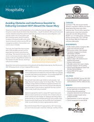
Additional wired APs cannot be connected to the bridged<br />
segment, as shown in Figure 3. The problem with this<br />
configuration is that because C can reach the ZoneDirector<br />
through mesh link B-A, and because C has its Ethernet port<br />
active, it meets both conditions (ZoneDirector reachable,<br />
and Ethernet in use) to advertise that it is a root — even<br />
though it is NOT a root. As a result, this is an illegal topology.<br />
However, additional wireless MAPs may be added in this<br />
physical location for additional coverage and capacity. In the<br />
example in Figure 3, RAP-C is NOT ALLOWED, as it is connected<br />
via Ethernet to this bridged wired segment. However<br />
using wireless MAP-D to extend the mesh is ALLOWED.<br />
Root AP (A) <strong>Mesh</strong> AP (B)<br />
Root AP (C)<br />
Choosing the Right AP Model<br />
<strong>Mesh</strong> AP (D)<br />
Figure 3: <strong>Mesh</strong> — Illegal Bridge Topology<br />
Ruckus supports both 802.11g, and the newer, faster, dualband<br />
802.11n APs with which to form a Smart <strong>Mesh</strong> network.<br />
In the dual-band models, ZoneFlex 7962 (indoor) or the 7762<br />
(outdoor), mesh links run on the 5 GHz band, with client<br />
access at 2.4 and 5 GHz. Smart <strong>Mesh</strong>ing also works with<br />
802.11g APs, the Ruckus ZoneFlex 2942 and 2925 (indoor) or<br />
the 2741 (outdoor). These products can be used to form a<br />
highly reliable Smart <strong>Mesh</strong> network.<br />
Page 2
<strong>Wireless</strong> <strong>Mesh</strong> <strong>Best</strong> <strong>Practice</strong> <strong>Guide</strong><br />
It’s important to note that 802.11g and 802.11n technology<br />
cannot be mixed in a mesh topology. All nodes in a mesh<br />
must be dual-band 802.11n (ZF 7962 or 7762), or single band<br />
802.11ng (ZF 7942) or 802.11g (ZF 2942 or 2741 or 2925).<br />
In summary, build your mesh network as follow:<br />
i. Ensure that all APs are dual-band 802.11n — model ZF 7962<br />
or 7762 (can mix)<br />
ii. Ensure that all APs are single band 802.11ng — model<br />
ZF 7942<br />
iii. Ensure that all APs are 802.11g — model ZF 2942 or 2741 or<br />
2942 (can mix)<br />
NoTe: The above restrictions apply only to AP-AP communcation<br />
as part of a mesh — not to AP-Client communication.<br />
For example, there is no problem for 802.11g clients to connect<br />
to an 802.11n mesh.<br />
Indoor Planning: Calculating the Number<br />
of APs Required<br />
Optimizing coverage and performance are critical aspects to<br />
planning a Smart <strong>Mesh</strong> infrastructure. Calculating the number<br />
of total APs (RAPs and MAPs) that are needed to provide<br />
adequate coverage and performance for a given property is<br />
the one of the first steps.<br />
If the goal is to support Internet grade connections for casual<br />
Web browsing, a design that delivers 1 Mbps of throughput<br />
in the entire coverage area is adequate. For Enterprise grade<br />
connections, plan for 10 Mbps of throughput. <strong>Wireless</strong> is a<br />
shared medium, of course, so this aggregate bandwidth will<br />
be shared amongst the concurrent users at any given time.<br />
So if the network is designed to support 10 Mbps, it would<br />
support 1 user at 10 Mbps, or 10 users at 1 Mbps each. In<br />
reality, due to statistical multiplexing (just like the phone<br />
system — the fact that not all users are using the network<br />
concurrently, if an oversubscription ratio of 4:1 is used, such a<br />
network could actually support 40 users @ 1Mbps.<br />
To plan for coverage and performance, understanding<br />
wireless mesh technology and its impact on performance is<br />
essential. A Root AP (RAP) in a Smart <strong>Mesh</strong> network has all its<br />
bandwidth available for downlink because the uplink is wired.<br />
However for mesh APs (MAPs), the available wireless bandwidth<br />
must be shared between the uplink and the downlink.<br />
This degrades performance of a mesh AP as compared to a<br />
root. However, from a coverage perspective, it is no different<br />
to estimate the number of APs needed, regardless of a mesh<br />
or traditional non-mesh (i.e., all root) topology.<br />
Ruckus <strong>Wireless</strong> • <strong>Wireless</strong> <strong>Mesh</strong> <strong>Best</strong> <strong>Practice</strong> <strong>Guide</strong><br />
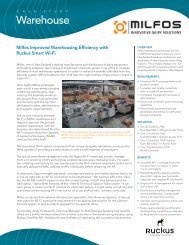
A simple and easy-to-use AP calculator, provided on the<br />
Big Dogs Partner Portal, helps determine how many Smart<br />
<strong>Mesh</strong> nodes (APs) are required for a given indoor area. It<br />
can be accessed at: http://partners.ruckuswireless.com/<br />
sales_tools/quoting_guide.<br />
The ZoneFlex AP calculator, as shown below, requires<br />
administrators to fill in some parameters regarding the<br />
environment such as square feet to cover, etc. After filling in<br />
these simple metrics, the program automatically generates<br />
the number of APs needed as well as a budgetary cost.<br />
Figure 4: ZoneFlex Budgetary Quoting <strong>Guide</strong><br />
outdoor Planning: Calculating the<br />
Number of APs Required<br />
For outdoor planning, a different methodology should be<br />
used to calculate the number of APs required. We will focus<br />
on calculating the minimum number of APs required for<br />
coverage at the desired performance level. If more capacity<br />
is needed, additional APs (MAPs and RAPs) may be added<br />
to the network.<br />
It is practical to consider a fixed area initially for the design,<br />
like 1 sq km. We will go through an outdoor design to cover<br />
1 sq km below, and this basic template can then be used to<br />
extend the network to an arbitrarily large area.<br />
First the user must define the performance levels (throughput)<br />
needed for the application. Ruckus provides a tool for<br />
estimating the throughput for a given coverage (distance)<br />
from the selected model of AP. This calculator tool is found<br />
at http://www.ruckuswireless.com/tools/performancecalculator.<br />
The tool can be used to estimate throughput at a certain<br />
distance for a mesh link (AP to AP) or for an AP to client link.<br />
Because the mesh links are the backbone of the wireless<br />
network, it is important to design the mesh links conservatively<br />
to ensure optimum performance. Ruckus recommends<br />
maximum mesh link distances of 350 meters for our<br />
outdoor 2741 and 7762 APs. For a 1 sq km area, the topology<br />
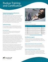
looks like the one shown below:<br />
Page 3
250m<br />
<strong>Wireless</strong> <strong>Mesh</strong> <strong>Best</strong> <strong>Practice</strong> <strong>Guide</strong><br />
<strong>Mesh</strong><br />
AP<br />
<strong>Mesh</strong><br />
AP<br />
<strong>Mesh</strong><br />
AP<br />
<strong>Mesh</strong><br />
AP<br />
<strong>Mesh</strong><br />
AP<br />
500m<br />
<strong>Mesh</strong><br />
AP<br />
Root<br />
AP<br />
<strong>Mesh</strong><br />
AP<br />
Root<br />
AP<br />
<strong>Mesh</strong><br />
AP<br />
<strong>Mesh</strong><br />
AP<br />
<strong>Mesh</strong><br />
AP<br />
354m<br />
<strong>Mesh</strong><br />
AP<br />
<strong>Mesh</strong><br />
AP<br />
<strong>Mesh</strong><br />
AP<br />
<strong>Mesh</strong><br />
AP<br />
Root<br />
AP<br />
<strong>Mesh</strong><br />
AP<br />
Root<br />
AP<br />
<strong>Mesh</strong><br />
AP<br />
Figure 5: Root Placement<br />
Also shown in the topology above is four roots — this<br />
ensures there is no more than a 1-hop mesh AP anywhere in<br />
this 1 x 1 km area.<br />
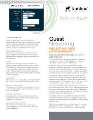
Using the calculator, we can estimate the performance of<br />
the above design. For the mesh links (AP to AP), the calculator<br />
parameters are entered as below. It is assumed in this<br />
example that the APs are located outdoors, LOS, with no<br />
obstructions in between.<br />
Figure 6: ZoneFlex Performance Calculator<br />
<strong>Mesh</strong> performance to the first hop is seen to be around 50<br />
Mbps.<br />
For client performance at 150m, the calculator is run as<br />
follows:<br />
Ruckus <strong>Wireless</strong> • <strong>Wireless</strong> <strong>Mesh</strong> <strong>Best</strong> <strong>Practice</strong> <strong>Guide</strong><br />
<strong>Mesh</strong><br />
AP<br />
<strong>Mesh</strong><br />
AP<br />
<strong>Mesh</strong><br />
AP<br />
<strong>Mesh</strong><br />
AP<br />
<strong>Mesh</strong><br />
AP<br />
Client<br />
coverage<br />
radius<br />
<br />
Figure 7: Client performance at 150m<br />
Assuming the client is an 802.11ng, and more susceptible to<br />
noise than an AP, we could expect client throughputs around<br />
60 Mbps. However, since the mesh performance is capped at<br />
50 Mbps, this puts an upper bound of 50 Mbps on the client.<br />
For 802.11g clients, you may use the following trick to estimate<br />
the performance. Leaving everything else the same on<br />
the calculator, select the 2741 802.11g AP from the pull-down<br />
menu. This shows that an 802.11g client at 150m can expect<br />
around 28 Mbps.<br />
It should be pointed out that the client-AP will be non-LOS<br />
more often than not, as compared to the outdoor mesh APs,<br />
which may be mounted on rooftops or poles and therefore<br />
have a good LOS link. For challenging (real-world) client connections,<br />
we recommend using a CPE product (e.g. Ruckus<br />
2211) to enhance client performance.<br />
Placement and Layout Considerations:<br />
i. Utilize two (2) or more RAPs: To prevent having a single<br />
point-of-failure, it is best to have two (2) or more RAPs so<br />
that there are alternate paths to the wired network. In the<br />
example above, the number of RAPs should be increased<br />
from one (1) to two (2) to meet this best practice.<br />
ii. Deploy as many roots as possible: As shown in Table 2, the<br />
more roots in the mesh topology, the higher the performance.<br />
Therefore, as far as possible, try to wire as many APs<br />
as is convenient. A useful way to look at this is a RAP:MAP<br />
ratio. Since all MAP traffic has to ultimately egress from the<br />
roots, it is useful to maintain a reasonable RAP:MAP ratio.<br />
For example, RAP:MAP of 1:3 would be best, 1:5 would be<br />
reasonable, and 1:7 or worse is not recommended.<br />
iii. Design for a three-hop maximum: Avoid excessive hops in<br />
your mesh topology. In general, the goal should be to have<br />
the lowest number of hops, provided other considerations<br />
(like signal >= 25%) are met. Limiting the number of hops to<br />
three (3) or less is best practice — 1 or 2 hops is ideal.<br />
Page 4<br />
<strong>Wireless</strong> <strong>Mesh</strong> <strong>Best</strong> <strong>Practice</strong> <strong>Guide</strong><br />
iv. Bring in the backhaul to the middle of coverage area:<br />
This allows the placement of the root AP towards the middle<br />
of a coverage area to minimize the # hops required to<br />
reach some MAPs.<br />
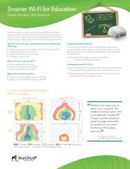
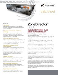
v. Distribute roots evenly throughout coverage area. If there<br />
are multiple roots within the Smart <strong>Mesh</strong>, ensure the roots<br />
are evenly dispersed throughout the coverage area (not<br />
clumped up close together in one area). Figure 8 illustrates<br />
an ideal scenario, along with a not-so-ideal scenario. While<br />
the purpose of a mesh network is to provide coverage in<br />
areas that are hard to wire, the ideal may not be possible. But<br />
as far as possible, evenly spaced out root APs are preferable.<br />
vi. Do not mount wireless backhaul near the AP. If the customer’s<br />
network utilizes a wireless backhaul technology<br />
for broadband access, it is recommended to not mount<br />
the broadband wireless modem right next to a Ruckus AP.<br />
A distance of 10’ or more would be desirable.<br />
Roots are evenly spaced. Preferred scenario. Roots are clumped together. Not ideal.<br />
= Root = <strong>Mesh</strong><br />
Figure 8: Root Placement<br />
Signal Quality Verification<br />
The above guidelines for planning will result in a welldesigned<br />
Smart <strong>Mesh</strong> infrastructure. Once the Smart<strong>Mesh</strong> is<br />
deployed there are useful parameters within the system GUI<br />
that should be monitored to ensure the mesh is operating<br />
optimally. One such parameter is the “signal value” in the<br />
ZoneDirector. Signal is a measurement of the link quality of<br />
the MAP’s uplink.<br />
To view the signal parameter in the Zone Director GUI,<br />
navigate to the Monitor --> Access Points section. Then, click<br />
on the MAP being tested (click the MAC address) to see the<br />
Access Point detail screen, as shown below. There are two<br />
best practice observations that should be met:<br />
Signal Value <strong>Best</strong> <strong>Practice</strong><br />
i. Ensure signal >= 25%: The signal value under Neighbor<br />
APs that shows Connected should be 25% or better. If<br />
the value is lower, the AP needs to be placed closer, or<br />
moved to avoid an obstruction so the value of signal to<br />
25% or better. For a more conservative design, you may<br />
use 30% as your signal benchmark.<br />
Ruckus <strong>Wireless</strong> • <strong>Wireless</strong> <strong>Mesh</strong> <strong>Best</strong> <strong>Practice</strong> <strong>Guide</strong><br />
ii. Ensure a minimum of two uplink options for every MAP:<br />
In addition, under Neighbor APs, it is best practice that<br />
there exists an alternate path for this Smart <strong>Mesh</strong> uplink.<br />
This alternate path must also have a signal value of 25% or<br />
better. In other words, there should be at least two possible<br />
links that the MAP can use for uplink and both must have a<br />
signal value of 25% or better.<br />
iii. AP-AP throughput of 12 Mbps: In addition to the signal<br />
value recommendations, it is recommended to test actual<br />
throughput between the mesh links to verify reliable<br />
operation. The ZoneDirector GUI allows the operator to run<br />
SpeedFlex between any RAP-MAP, or MAP-MAP pair. It is<br />
recommended that a throughput of 12 Mbps is achieved on<br />
any pair of parent-child APs.<br />
Figure 9: <strong>Mesh</strong> status and topology<br />
Channel and Tx Power <strong>Best</strong> <strong>Practice</strong><br />
There are no channel and power settings to worry about — the<br />
<strong>Mesh</strong> APs automatically select the best channel and power settings.<br />
The APs use 802.11h to communicate with each other to<br />
ensure that the entire mesh tree synchronously changes channels,<br />
thus not stranding any AP. Also, preference is given to the<br />
busiest roots when it comes to assigning channel.<br />
Mounting and orientation of APs<br />
It is important that the APs be mounted with the correct<br />
orientation to ensure that reliable mesh links can be formed.<br />
There are five ZoneFlex AP models that support Smart <strong>Mesh</strong><br />
Networking:<br />
• dual-band 802.11abgn: ZoneFlex 7962 (indoor) and<br />
ZoneFlex 7762 (outdoor)<br />
• single-band 802.11ng: ZoneFlex 7942<br />
• 802.11g: ZoneFlex 2942 (indoor), ZoneFlex 2741 (outdoor),<br />
and ZoneFlex 2925 (desktop model)<br />
In general, these and other Ruckus APs are very tolerant to a<br />
variety of mounting and orientation options due to Ruckus’ use<br />
of its unique BeamFlex technology in which the RF signal is<br />
dynamically concentrated and focused towards the other end<br />
of the RF link.<br />
Page 5<br />
<strong>Wireless</strong> <strong>Mesh</strong> <strong>Best</strong> <strong>Practice</strong> <strong>Guide</strong><br />
The bottom line regarding orientation and placement<br />
is that during the planning phase, it is advisable to use<br />
the Signal quality as your benchmark, as explained in the<br />
Signal Quality Verification section. Ensure that the Signal<br />
is better than 25% for trouble-free operation. For a more<br />
conservative design, and for larger mesh networks, use<br />
30% signal as the benchmark.<br />
For additional mounting details, please also consult the<br />
Quick Setup <strong>Guide</strong> and the Wall and Ceiling Mounting<br />
Instructions that came in the AP box.<br />
Indoor APs – Typical Case: Horizontal Orientation<br />
For the ZoneFlex 7962, 7942 and 2942, the APs are typically<br />
oriented such that their dome is pointing straight down.<br />
Wallmount<br />
2942/7942/7962<br />
dome pointing<br />
down<br />
2942/7942/7962 dome<br />
pointing straight down<br />
Figure 10: ZoneFlex 2942/7942/7962 Horizontal orientation<br />
For the ZoneFlex 2925, the AP is typically oriented so that<br />
the FCC/CE label, or the serial number and MAC label on the<br />
underside of the unit, is horizontally oriented, as shown in<br />
Figure 11: ZoneFlex 2925 Horizontal orientation<br />
Ruckus <strong>Wireless</strong> • <strong>Wireless</strong> <strong>Mesh</strong> <strong>Best</strong> <strong>Practice</strong> <strong>Guide</strong><br />
figure 11.<br />
Indoor APs – Less Typical Vertical Orientation<br />
A less typical vertical orientation may be used in certain cases<br />
where it is not possible for mechanical or aesthetic reasons to<br />
use the typical orientation. In such cases, the indoor APs may<br />
Figure 12: ZoneFlex 2942/7942 Vertical orientation<br />
Figure 13: ZoneFlex 2925 Vertical orientation<br />
be mounted vertically, and will still provide good coverage.<br />
Examples of vertical mounting are shown in Figures 12 and 13.<br />
Outdoor APs – Horizontal Orientation<br />
There are two (2) outdoor AP models — the ZoneFlex 7962<br />
<br />
Page 6<br />
<strong>Wireless</strong> <strong>Mesh</strong> <strong>Best</strong> <strong>Practice</strong> <strong>Guide</strong><br />
and the ZoneFlex 2741. In both cases, a typical orientation is<br />
horizontal, as shown in Figure 14.<br />
The most common placement of the outdoor AP is on a rooftop<br />
or on top of a pole, or some other elevated location, and<br />
with the dome pointing down. This has the benefit of good<br />
quality, LOS mesh links.<br />
Less common is to place the AP on a lower elevation and<br />
point upwards towards the face of a building. However, this<br />
is a perfectly acceptable way to mount the AP, and is used to<br />
provide service in many hotels and apartments.<br />
Below are some ways to mount the Ruckus outdoor AP — on<br />
roof-tops, cell towers, or light poles.<br />
Elevation of RAPs and MAPs<br />
In addition to orientation, it is important to pay attention to<br />
the elevation of an AP for reliable mesh operation. Large differences<br />
in elevation should be avoided. Whether deployed<br />
as an indoor mesh, an outdoor mesh, or a mixed indooroutdoor<br />
mesh, MAPs and RAPs should all be at a similar<br />
elevation from the ground, if possible.<br />
Additional outdoor <strong>Best</strong> <strong>Practice</strong>s<br />
For outdoor deployments, it is important to consider some<br />
additional best practices around surge suppression, and<br />
power sources, including solar.<br />
Surge Suppressors<br />
When deploying APs outdoors, it is advisable to use surge<br />
suppressors on the POE Ethernet cable that is carrying<br />
power and data to the AP. These should be installed in-line<br />
into the cabling, and are typically grounded. Please follow<br />
the manufacturer’s recommendations for installation and<br />
operation. A well-known supplier of such parts is Transtector.<br />
More details can be found at http://www.transtector.com/<br />
ProductData?class=Ethernet<br />
Power Sources<br />
Street Light Power Options<br />
If the APs are to be mounted on street light poles, and power<br />
needs to be sourced from the poles, there is typically AC<br />
available at the top of the pole (light unit), where there is<br />
normally a photo-electric control unit plugged in. There are<br />
Ruckus <strong>Wireless</strong> • <strong>Wireless</strong> <strong>Mesh</strong> <strong>Best</strong> <strong>Practice</strong> <strong>Guide</strong><br />
products on the market that plug into this AC receptacle<br />
and provide 802.3af output that can be used to power the<br />
AP. The photo-electric unit is plugged back into this unit, as<br />
shown in the picture.<br />
Make sure the voltages in the country you are operating<br />
meet the specifications of the PoE street light power module<br />
— AC voltage could vary from 100V to 480V. The basic steps<br />
are as follows — provided as a general guideline. Make sure<br />
to follow the manufacturer’s steps for this.<br />
1. Turn off power<br />
2. Unscrew existing photo-electric control<br />
3. Replace with Streetlight POE injector device<br />
4. Put back the photo-electric control<br />
5. Run outdoor Ethernet cable to Access Point<br />
6. Cover the photo-electric control to verify lamp is able<br />
to arc<br />
Two vendors that make such devices are www.sbwireless.<br />
com and www.fpolc.com<br />
Solar Power <strong>Best</strong> <strong>Practice</strong><br />
There are many instances where<br />
it may be required to power the<br />
AP off alternate energy sources<br />
like wind or solar.<br />
There are a number of good options for solar panels and<br />
associated equipment. With some care in the planning and<br />
design of a solar system, there is no reason this cannot be a<br />
reliable source of power for an outdoor AP.<br />
Some of the key issues for a reliable design are:<br />
• Desired service level?<br />
• Budget for project<br />
• Average peak sun hours for location?<br />
• How many possible days of no sun?<br />
• How much current is needed?<br />
• Base line<br />
• Headroom for future products<br />
• Total current of system<br />
• High Temp of the year<br />
<br />
Page 7
<strong>Wireless</strong> <strong>Mesh</strong> <strong>Best</strong> <strong>Practice</strong> <strong>Guide</strong><br />
• Low temp of the year<br />
• Highest Humidity of the year<br />
Let us use an example to design a system. Let us assume the<br />
following requirements for this example design:<br />
1. 24 by 7 by 365 up time<br />
2. Longest June 21-14H, Shortest Dec 21-10H<br />
a. Refer to average peak sun hours for location, 8H<br />
3. Built to withstand 3 days of no sun<br />
4. Maximum current draw for system<br />
a. 3A<br />
b. How much headroom for future, 1A<br />
c. Total 4A<br />
5. High temp of 50°C<br />
6. Low temp of 0°C<br />
7. Max Humidity 90%<br />
Average Peak Sun Hours Per Day<br />
The simple chart below can be used to estimate the daily<br />
charging time in hours. Shown in the chart are conservative<br />
numbers. Actual charging time is more due to more daylight<br />
hours in a day.<br />
With the design requirements and information above, and<br />
assuming units run-time is 24 hours per day (unit in service for<br />
24 out of 24 hours per day), the table below will help us size<br />
the batteries and solar panels.<br />
From the table, we can compute how many amps per day are<br />
used, what kind of battery is appropriate size, and what kind<br />
of solar panel can re-charge the battery. So from left to right,<br />
here’s how to read the first row, for example:<br />
Product Unit current<br />
drain “dcA”<br />
Run time<br />
“Hours”<br />
Amps per<br />
day usage<br />
Ruckus <strong>Wireless</strong> • <strong>Wireless</strong> <strong>Mesh</strong> <strong>Best</strong> <strong>Practice</strong> <strong>Guide</strong><br />
• 2741 draws 1A, over 24 hours that is 24 Ah.<br />
• For a Group 24 battery, with up to 75% drain allowed<br />
(75% of 70-85 Ah), it will be able to keep the unit powered<br />
and running for 2 whole days, even if no sun.<br />
• If we used the 65W panel, which can put back 36A over<br />
a 10 hour sun period in a day, we could re-charge up to<br />
1 day’s battery charge loss, in approx. ½ day.<br />
Below is shown, our sample system design. Also provided<br />
are links to vendors who manufacture the different components.<br />
The solar charge controller is recommended to<br />
prevent over-charging the battery. The vendor links are<br />
repeated here:<br />
Solar panels:<br />
http://www.ecodirect.com/BP-Solar-SX-365J-65-Watt-12-<br />
Volt-p/bp-solar-sx-365j.htm<br />
Deep cycle battery types, current per<br />
cell “amp hours” @ 24 Hours, Backup<br />
power if no sun @ 75% drain<br />
Group 24<br />
70-85Ah<br />
$99 avg<br />
2741/7731 1A 24 24 2 days of<br />
no sun @<br />
85Ah<br />
7762 1.5A 24 36 1 day of no<br />
sun @85Ah<br />
NOTE: Based on<br />
back panel<br />
info, but<br />
might be<br />
less<br />
How<br />
many<br />
hours<br />
unit<br />
will run<br />
a day,<br />
typical is<br />
24 hours<br />
Take max<br />
current*<br />
the<br />
number of<br />
hours<br />
Group 27<br />
85-105Ah<br />
$160 avg<br />
3 days of<br />
no sun<br />
@105Ah<br />
2 days of<br />
no sun<br />
@105Ah<br />
Group 31<br />
95-125Ah<br />
$200 avg<br />
4 days of<br />
no sun<br />
@125Ah<br />
3 days of<br />
no sun<br />
@125Ah<br />
Not good to take deep cycle batteries<br />
below 75% discharge, also depends<br />
on type of batteries, see MFG<br />
instructions, above is worst case.<br />
Much larger batteries are available,<br />
4-D and 8-D have up to 225Ah<br />
Solar panel size/number of hours of<br />
charging time<br />
80W, 4.6A<br />
max $450<br />
10 hours<br />
46A day<br />
10 hours<br />
46A day<br />
65W, 3.7A<br />
max $400<br />
10 hours<br />
36A day<br />
10 hours<br />
36A day<br />
Lots of different types<br />
and outputs. Note<br />
product’s DC voltage<br />
limits, high and low, to<br />
ensure product is not<br />
damaged<br />
Full sun on<br />
system, it will<br />
recharge in<br />
1/2 a day<br />
Full sun on<br />
system, it will<br />
recharge in<br />
3/4 of a day<br />
Page 8
<strong>Wireless</strong> <strong>Mesh</strong> <strong>Best</strong> <strong>Practice</strong> <strong>Guide</strong><br />
Battery Information<br />
http://www.windsun.com/Batteries/Battery_FAQ.<br />
htm#AGM,%20or%20Absorbed%20Glass%20Mat%20<br />
Batteries<br />
http://www.google.com/products?client=safari&rls=en&q=g<br />
roup+27+AGM+battery&oe=UTF-8&um=1&ie=UTF-8&ei=5x<br />
1OS4_6BYvKsAPskNzOBw&sa=X&oi=product_result_group<br />
&ct=image&resnum=3&ved=0CB8QzAMwAg<br />
Solar Charge Controller<br />
http://www.morningstarcorp.com/en/products<br />
Sample system<br />
Solar panel<br />
• This is a BP 65W 12vdc panel — $390<br />
http://www.ecodirect.com/BP-Solar-SX-365J-65-Watt-<br />
12-Volt-p/bp-solar-sx-365j.htm<br />
Solar charge controller
<strong>Wireless</strong> <strong>Mesh</strong> <strong>Best</strong> <strong>Practice</strong> <strong>Guide</strong><br />
<strong>Best</strong> <strong>Practice</strong> checklist<br />
1. Ensure you do not have any illegal bridge topologies in your Smart<br />
<strong>Mesh</strong> network.<br />
2. Ensure sure Smart <strong>Mesh</strong> APs are mounted with the optimum orientation<br />
for maxi-mum coverage.<br />
3. Try to place Smart <strong>Mesh</strong> APs at the same (or close to the same)<br />
elevation from ground.<br />
4. Don’t mix 802.11n and 802.11g APs within the Smart <strong>Mesh</strong>. They<br />
will NOT mesh properly.<br />
5. Calculate the number of RAPs and MAPs required using the<br />
instructions and exam-ples provided.<br />
6. Deploy two or more root APs so there is an alternate path for reliability,<br />
even when capacity and coverage only require one.<br />
7. Avoid excessive mesh hops. Ideally keep the mesh hop count to<br />
three hops or less.<br />
8. Deploy as many roots as feasible for better performance.<br />
9. Place a root AP near the middle of a coverage area to minimize the<br />
number of hops required reach any given MAP.<br />
10. For multiple root APs, ensure the roots are distributed evenly<br />
throughout the cov-erage area.<br />
11. Use the signal quality measurement to ensure that the connected<br />
MAP uplink is 25% or better.<br />
12. Try to maintain more than one uplink path for every MAP, ensuring<br />
the signal value of the alternate path is also 25% or better.<br />
13. Use a surge suppressor outdoors for safety.<br />
14. Follow the solar best practices for a reliable design.<br />
Ruckus <strong>Wireless</strong>, Inc.<br />
880 West Maude Avenue, Suite 101, Sunnyvale, CA 94085 USA (650) 265-4200 Ph \ (408) 738-2065 Fx<br />
Copyright © 2010, Ruckus <strong>Wireless</strong>, Inc. All rights reserved. Ruckus <strong>Wireless</strong> and Ruckus <strong>Wireless</strong> design are registered in the U.S. Patent and Trademark<br />
Office. Ruckus <strong>Wireless</strong>, the Ruckus <strong>Wireless</strong> logo, BeamFlex, ZoneFlex, MediaFlex, MetroFlex, FlexMaster, ZoneDirector, SpeedFlex, SmartCast, and<br />
Dynamic Ruckus PSK are trademarks <strong>Wireless</strong> of Ruckus • <strong>Wireless</strong> <strong>Wireless</strong>, <strong>Mesh</strong> Inc. in the <strong>Best</strong> United <strong>Practice</strong> States and other <strong>Guide</strong> countries. All other trademarks mentioned in this document or<br />
website are the property of their respective owners. 805-71754-001 rev 02<br />
www.ruckuswireless.com Page 10