2006 Infiniti M45 Owner Guide - Infiniti Service Information
2006 Infiniti M45 Owner Guide - Infiniti Service Information
2006 Infiniti M45 Owner Guide - Infiniti Service Information

Create successful ePaper yourself
Turn your PDF publications into a flip-book with our unique Google optimized e-Paper software.
Foreword<br />
Your INFINITI represents a new way of<br />
thinking about vehicle design. It integrates<br />
advanced engineering and superior<br />
craftsmanship with a simple, refined aesthetic<br />
sensitivity associated with traditional<br />
Japanese culture.<br />
The result is a different notion of luxury<br />
and beauty. The car itself is important, but<br />
so is the sense of harmony that the vehicle<br />
evokes in its driver, and the sense of satisfaction<br />
you feel with the INFINITI — from<br />
the way it looks and drives to the high level<br />
of dealer service.<br />
To ensure that you enjoy your INFINITI to<br />
the fullest, we encourage you to read this<br />
<strong>Owner</strong>’s Manual immediately. It explains<br />
all of the features, controls and performance<br />
characteristics of your INFINITI; it<br />
also provides important instructions and<br />
safety information.<br />
A separate Warranty <strong>Information</strong> Booklet is included<br />
in your <strong>Owner</strong>’s literature portfolio. The<br />
INFINITI <strong>Service</strong> and Maintenance <strong>Guide</strong> explains<br />
details about maintaining and servicing<br />
your vehicle. Always carry it with you when you<br />
take your vehicle to an INFINITI dealer. The<br />
Warranty <strong>Information</strong> Booklet contents provide<br />
complete information about all warranties<br />
covering this vehicle, the requirements to keep<br />
the warranties in effect as well as the INFINITI<br />
Roadside Assistance program.<br />
Additionally, a separate Customer Care<br />
and Lemon Law <strong>Information</strong> Booklet will<br />
explain how to resolve any concerns you<br />
may have with your vehicle, as well as<br />
clarify your rights under your state’s<br />
lemon law.<br />
INFINITI is dedicated to providing a satisfying<br />
ownership experience for as long as<br />
you own your car. Should you have any<br />
questions regarding your INFINITI or your<br />
INFINITI dealer, please contact our Consumer<br />
Affairs department at:<br />
In U.S. 1-800-662-6200.<br />
In Canada 1-800-361-4792.<br />
READ FIRST — THEN DRIVE SAFELY<br />
Before driving your vehicle, read your<br />
<strong>Owner</strong>’s Manual carefully. This will ensure<br />
familiarity with controls and maintenance<br />
requirements, assisting you in the safe operation<br />
of your vehicle.<br />
WARNING<br />
IMPORTANT SAFETY INFORMATION<br />
REMINDERS FOR SAFETY!<br />
Follow these important driving rules to help<br />
ensure a safe and comfortable trip for you and<br />
your passengers!<br />
NEVER drive under the influence of alcohol<br />
or drugs.<br />
ALWAYS observe posted speed limits and<br />
never drive too fast for conditions.<br />
ALWAYS use your seat belts and appropriate<br />
child restraint systems. Pre-teen<br />
children should be seated in the rear<br />
seat.<br />
ALWAYS provide information about the<br />
proper use of vehicle safety features to all<br />
occupants of the vehicle.<br />
ALWAYS review this <strong>Owner</strong>’s Manual for<br />
important safety information.<br />
MODIFICATION OF YOUR VEHICLE<br />
This vehicle should not be modified. Modification<br />
could affect its performance,<br />
safety or durability, and may even violate<br />
governmental regulations. In addition,<br />
damage or performance problems resulting<br />
from modification will not be covered<br />
under the INFINITI warranties.<br />
WHEN READING THE MANUAL<br />
This manual includes information for all<br />
options available on this model. Therefore,<br />
you may find some information that<br />
does not apply to your vehicle.
All information, specifications and illustrations<br />
in this manual are those in effect at<br />
the time of printing. INFINITI reserves the<br />
right to change specifications or design at<br />
any time without notice.<br />
IMPORTANT INFORMATION ABOUT<br />
THIS MANUAL<br />
You will see various symbols in this<br />
manual. They are used in the following<br />
ways:<br />
WARNING<br />
This is used to indicate the presence of a<br />
hazard that could cause death or serious personal<br />
injury. To avoid or reduce the risk, the<br />
procedures must be followed precisely.<br />
CAUTION<br />
This is used to indicate the presence of a<br />
hazard that could cause minor or moderate<br />
personal injury or damage to your vehicle. To<br />
avoid or reduce the risk, the procedures must<br />
be followed carefully.<br />
SIC0697<br />
If you see the symbol above, it means “Do<br />
not do this” or “Do not let this happen”.<br />
If you see a symbol similar to those above<br />
in an illustration, it means the arrow points<br />
to the front of the vehicle.<br />
Arrows in an illustration that are similar to<br />
those above indicate movement or action.<br />
Arrows in an illustration that are similar to<br />
those above call attention to an item in the<br />
illustration.<br />
CALIFORNIA PROPOSITION 65<br />
WARNING<br />
WARNING<br />
Engine Exhaust, some of its constituents,<br />
and certain vehicle components contain or<br />
emit chemicals known to the State of California<br />
to cause cancer and birth defects or other<br />
reproductive harm. In addition, certain fluids<br />
contained in vehicles and certain products of<br />
component wear contain or emit chemicals<br />
known to the State of California to cause cancer<br />
and birth defects or other reproductive<br />
harm.<br />
BLUETOOTH is a trademark<br />
owned by Bluetooth SIG,<br />
Inc., U.S.A. and licenced to<br />
Xanavi Informatics Corporation.<br />
© 2005 NISSAN MOTOR CO., LTD.<br />
TOKYO, JAPAN<br />
All rights reserved. No part of this <strong>Owner</strong>’s Manual<br />
may be reproduced or stored in a retrieval system,<br />
or transmitted in any form, or by any means, electronic,<br />
mechanical, photocopying, recording or<br />
otherwise, without the prior written permission of<br />
Nissan Motor Co., Ltd.
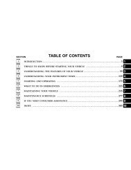
Table of<br />
Contents<br />
Illustrated table of contents 0<br />
Safety — Seats, seat belts and supplemental restraint system 1<br />
Instruments and controls 2<br />
Pre-driving checks and adjustments 3<br />
Monitor, climate, audio, phone and voice recognition systems 4<br />
Starting and driving 5<br />
In case of emergency 6<br />
Appearance and care 7<br />
Maintenance and do-it-yourself 8<br />
Technical and consumer information 9<br />
Index 10
0 Illustrated table of contents<br />
Exterior front .................................................... 0-2<br />
Exterior rear ..................................................... 0-3<br />
Passenger compartment ................................... 0-4<br />
Cockpit............................................................. 0-6<br />
Instrument panel ............................................. 0-7<br />
Meters and gauges........................................... 0-8<br />
Engine compartment......................................... 0-9<br />
VK45DE engine ........................................... 0-9<br />
VQ35DE engine ......................................... 0-10
EXTERIOR FRONT<br />
1. Hood (Page 3-18)<br />
2. Headlight and turn signal switch<br />
— Operation (P.2-26)<br />
— Bulb replacement (P.8-32)<br />
— Adaptive Front lighting System (AFS)<br />
(if so equipped) (P.2-29)<br />
0-2 Illustrated table of contents<br />
SSI0088<br />
3. Windshield wiper and washer switch<br />
— Operation (P.2-25)<br />
— Blade replacement (P.8-23)<br />
4. Sunroof (P.2-46)<br />
5. Power windows (P.2-44)<br />
6. Recovery hook (P.6-17)<br />
7. Fog lights (P.2-31)<br />
8. Tires<br />
— Wheel and tires (P.8-35, P.9-9)<br />
— Flat tire (P.6-2)<br />
9. Outside mirrors (P.3-25)<br />
10. Doors<br />
— Keys (P.3-2)<br />
— Door locks (P.3-5)<br />
— Intelligent Key (P.3-8)
EXTERIOR REAR<br />
1. High-mounted stop light (Bulb replacement)<br />
(P.8-31)<br />
2. Rear window defroster switch (P.2-26)<br />
3. Rear combination light (Bulb replacement)<br />
(P.8-31)<br />
4. Fuel-filler door<br />
— Operation (P.3-21)<br />
— Fuel recommendation (P.9-3)<br />
5. Trunk lid (P.3-18)<br />
6. Child safety locks (P.3-7)<br />
SSI0089<br />
Illustrated table of contents 0-3
PASSENGER COMPARTMENT<br />
1. Rear sunshade (if so equipped)<br />
(P.2-48)<br />
2. Top tether strap anchors (P.1-26)<br />
3. Interior lights (P.2-49)<br />
0-4 Illustrated table of contents<br />
SSI0099<br />
4. Flip-down screen (if so equipped)<br />
(P.4-47)<br />
5. Seat belts (P.1-8)<br />
6. Supplemental curtain side-impact air<br />
bags (P.1-36)<br />
7. Seats (P.1-2)<br />
8. Power windows (P.2-44)<br />
9. Sun visors (P.3-23)<br />
10. Sunroof (P.2-46)<br />
11. Sunglasses holder (P.2-41)<br />
12. Front passenger air bag and status<br />
light (P.1-44)<br />
13. Automatic anti-glare mirror,<br />
HomeLink (if so equipped) (P.3-24,<br />
P.2-51)<br />
14. Trunk pass-through (P.1-7)/Rear armrest<br />
(P.1-7)<br />
15. LATCH (Lower Anchors and Tethers for<br />
CHildren) system (P.1-24)<br />
16. Rear seat controls (if so equipped)<br />
— Rear power seat adjust switch<br />
(P.1-4)<br />
— Heated seat ON/OFF switch<br />
(P.2-33)<br />
— Automatic return ON/CANCEL<br />
switch (P.1-5)<br />
— Rear sunshade control switch<br />
(P.2-48)<br />
17. Rear passenger control switches (if so<br />
equipped)<br />
— For temperature (P.4-29)
— For audio (P.4-44)<br />
18. Rear cup holders (P.2-39)<br />
19. Supplemental side air bags (P.1-36)<br />
20. Front console (P.2-42)/Front armrest<br />
(P.1-7)<br />
21. Front cup holders (P.2-40)<br />
22. Front seat controls (if so equipped)<br />
— Climate controlled seat adjusting<br />
knob (P.2-34)<br />
— Rear sunshade control switch<br />
(P.2-48)<br />
— Rear passenger controls<br />
ON/CANCEL switch (P.2-48)<br />
— SNOW MODE ON/OFF switch<br />
(P.2-36)<br />
Illustrated table of contents 0-5
COCKPIT<br />
1. Instrument brightness control switch<br />
(P.2-30)<br />
2. Outside mirror remote control (P.3-25)<br />
3. Adaptive Front lighting System (AFS)<br />
switch (if so equipped) (P.2-29)<br />
0-6 Illustrated table of contents<br />
SSI0090<br />
4. Vehicle Dynamic Control (VDC) OFF<br />
switch (P.2-36)<br />
5. Headlight, fog light and turn signal<br />
switch (P.2-26)<br />
6. Steering-wheel-mounted controls (Left<br />
side)<br />
— ENTER switch (P.4-6, P.4-42)<br />
— BACK switch (P.4-43)<br />
— TALK switch (P.4-66)/Phone switch<br />
(P.4-58)<br />
— Volume control switches (P.4-43)<br />
— Source select switch (P.4-43)<br />
7. Windshield wiper and washer switch<br />
(P.2-25)<br />
8. Steering-wheel-mounted controls<br />
(Right side)<br />
— Cruise control switches (P.5-18)<br />
— Intelligent Cruise Control (ICC)<br />
switches (if so equipped) (P.5-20)<br />
9. Hood release handle (P.3-18)<br />
10. Trunk lid release switch (P.3-19)<br />
11. Lane Departure Warning (LDW) switch<br />
(if so equipped) (P.2-35)<br />
12. Intelligent Key port (P.5-8)<br />
13. Tilting/telescopic steering wheel<br />
switch (P.3-22)<br />
14. Steering wheel<br />
— Horn (P.2-32)<br />
— Driver supplemental air bag<br />
(P.1-36)
INSTRUMENT PANEL<br />
1. Side ventilator (P.4-23)<br />
2. Meters and gauges (P.2-4)<br />
3. Center ventilator (P.4-23)<br />
4. Security indicator light (P.2-24)<br />
5. Hazard warning flasher switch<br />
(P.2-32)<br />
6. Automatic climate control system<br />
(P.4-25)<br />
7. Center multi-function control panel<br />
SSI0091<br />
— Navigation system (if so equipped)<br />
— Vehicle information and setting buttons<br />
(P.4-7)<br />
— Phone system (P.4-59)<br />
— Audio system (P.4-30)<br />
8. Front passenger supplemental air bag<br />
(P.1-36)<br />
9. Fuse box cover (P.8-28)<br />
10. Parking brake pedal<br />
— Parking (P.5-44)<br />
— Maintenance (P.8-25)<br />
11. Push-button ignition switch (P.5-7)<br />
12. Clock (P.2-37)<br />
13. Cigarette lighter and ashtrays<br />
(P.2-38)<br />
14. Audio system (P.4-30)<br />
15. Glove box lid release button (P.2-41)<br />
16. Bluetooth in-vehicle phone<br />
module (P.4-59)/DVD drive for navigation<br />
system (if so equipped) (P.4-46)<br />
17. Trunk release power cancel switch<br />
(P.3-19)<br />
Illustrated table of contents 0-7
METERS AND GAUGES<br />
1. Engine coolant temperature gauge<br />
(P.2-6)<br />
2. Tachometer (P.2-5)<br />
3. Warning/indicator lights (P.2-11)<br />
4. Speedometer (P.2-5)<br />
0-8 Illustrated table of contents<br />
SSI0092<br />
5. Fuel gauge (P.2-6)<br />
6. Meter illumination control knob (P.2-7)<br />
7. Dot matrix liquid crystal display<br />
(P.2-20)<br />
8. Odometer/twin trip odometer (P.2-5)<br />
9. TRIP/RESET knob for twin trip<br />
odometer (P.2-5)
ENGINE COMPARTMENT<br />
VK45DE ENGINE*<br />
1. Fuse/fusible link holder (P.8-26)<br />
2. Battery (P.8-18)<br />
3. Engine oil filler cap (P.8-14)<br />
SSI0097<br />
4. Brake fluid reservoir (P.8-17)<br />
5. Window washer fluid reservoir<br />
(P.8-18)<br />
6. Coolant reservoir (P.8-11)<br />
7. Power steering fluid reservoir (P.8-17)<br />
8. Radiator filler cap (P.8-10)<br />
9. Engine oil dipstick (P.8-13)<br />
10. Air cleaner (P.8-22)<br />
* Shown with the engine compartment access<br />
panels removed. For removal and<br />
replacement instructions, see “Engine<br />
compartment check locations” in the “8.<br />
Maintenance and do-it-yourself” section.<br />
Illustrated table of contents 0-9
VQ35DE ENGINE*<br />
1. Fuse/fusible link holder (P.8-26)<br />
2. Battery (P.8-18)<br />
3. Engine oil filler cap (P.8-14)<br />
0-10 Illustrated table of contents<br />
SSI0098<br />
4. Brake fluid reservoir (P.8-17)<br />
5. Window washer fluid reservoir<br />
(P.8-18)<br />
6. Coolant reservoir (P.8-11)<br />
7. Power steering fluid reservoir (P.8-17)<br />
8. Radiator filler cap (P.8-10)<br />
9. Engine oil dipstick (P.8-13)<br />
10. Air cleaner (P.8-22)<br />
* Shown with the engine compartment access<br />
panels removed. For removal and<br />
replacement instructions, see “Engine<br />
compartment check locations” in the “8.<br />
Maintenance and do-it-yourself” section.
1 Safety — Seats, seat belts and supplemental<br />
restraint system<br />
Seats................................................................ 1-2<br />
Front seats.................................................. 1-2<br />
Rear seats................................................... 1-4<br />
Head restraint ............................................. 1-5<br />
Armrest ....................................................... 1-7<br />
Seat belts......................................................... 1-8<br />
Precautions on seat belt usage ................... 1-8<br />
Child safety............................................... 1-11<br />
Pregnant women ....................................... 1-12<br />
Injured persons ........................................ 1-12<br />
Pre-crash seat belts (front seats) (if so<br />
equipped) ................................................. 1-12<br />
Three-point type seat belt ......................... 1-13<br />
Seat belt extenders................................... 1-16<br />
Seat belt maintenance .............................. 1-16<br />
Child restraints............................................... 1-17<br />
Precautions on child restraints.................. 1-17<br />
Child restraint installation on rear seat<br />
center or outboard positions..................... 1-19<br />
LATCH (Lower Anchors and Tethers for<br />
CHildren) system....................................... 1-24<br />
Top tether strap child restraint ................. 1-26<br />
Child restraint installation on front<br />
passenger seat ......................................... 1-27<br />
Booster seats ................................................. 1-30<br />
Precautions on booster seats.................... 1-30<br />
Booster seat installation on rear seat<br />
center or outboard positions..................... 1-33<br />
Booster seat installation on front<br />
passenger seat ......................................... 1-35<br />
Supplemental restraint system ....................... 1-36<br />
Precautions on supplemental restraint<br />
system ...................................................... 1-36<br />
INFINITI advanced air bag system (front<br />
seats)........................................................ 1-42<br />
Supplemental side air bag and curtain<br />
side-impact air bag system ....................... 1-47<br />
Pre-tensioner seat belt system (front<br />
seats)........................................................ 1-49<br />
Supplemental air bag warning labels ........ 1-50<br />
Supplemental air bag warning light .......... 1-50<br />
Repair and replacement procedure............ 1-51
SEATS<br />
WARNING<br />
Do not ride in a moving vehicle when<br />
the seatback is reclined. This can be<br />
dangerous. The shoulder belt will not<br />
be against your body. In an accident,<br />
you could be thrown into it and receive<br />
neck or other serious injuries. You<br />
could also slide under the lap belt and<br />
receive serious internal injuries.<br />
1-2 Safety — Seats, seat belts and supplemental restraint system<br />
SSS0133B<br />
For the most effective protection when<br />
the vehicle is in motion, the seat<br />
should be upright. Always sit well back<br />
in the seat and adjust the seat belt<br />
properly. See “Precautions on seat belt<br />
usage” later in this section.<br />
FRONT SEATS<br />
Front power seat adjustment<br />
WARNING<br />
Do not adjust the driver’s seat while<br />
driving so full attention may be given<br />
to vehicle operation. The seat may<br />
<br />
move suddenly and could cause loss of<br />
control of the vehicle.<br />
Do not leave children unattended inside<br />
the vehicle. They could unknowingly activate<br />
switches or controls. Unattended<br />
children could become involved in serious<br />
accidents.<br />
Operating tips:<br />
The seat motor has an auto-reset overload<br />
protection circuit. If the motor<br />
stops during operation, wait 30 seconds,<br />
then reactivate the switch.<br />
Do not operate the power seat for a<br />
long period of time when the engine is<br />
off. This will discharge the battery.<br />
See “Automatic drive positioner” in the<br />
“3. Pre-driving checks and adjustments”
section for automatic drive positioner operation.<br />
SSS0474<br />
Forward and backward:<br />
on seat belt usage” later in this section.)<br />
The seatback may also be reclined to<br />
Moving the switch 1 forward or back-<br />
allow occupants to rest when the vehicle<br />
ward will slide the seat forward or back-<br />
is parked.<br />
ward to the desired position.<br />
Reclining:<br />
Move the recline switch 2 backward<br />
until the desired angle is obtained. To<br />
bring the seatback forward again, move<br />
the switch 2 forward.<br />
The reclining feature allows adjustment of<br />
the seatback for occupants of different<br />
sizes for added comfort and to help obtain<br />
proper seat belt fit. (See “Precautions<br />
Safety — Seats, seat belts and supplemental restraint system 1-3
Seat lifter:<br />
Push the front or rear end of the switch<br />
up or down to adjust the height and angle<br />
of the seat.<br />
For the front passenger’s seat, only the<br />
angle of the seat can be adjusted.<br />
1-4 Safety — Seats, seat belts and supplemental restraint system<br />
SSS0475 SSS0476 SSS0477<br />
Lumbar support (driver’s seat):<br />
The lumbar support feature provides<br />
lower back support to the driver. Push the<br />
front 1 or back 2 end of the switch to<br />
adjust the seat lumbar area.<br />
REAR SEATS<br />
Rear power seat adjustment (if so<br />
equipped)<br />
Forward and backward:<br />
Push the front 1 or back 2 end of the<br />
switch to move the rear outboard seats<br />
forward or backward. The seats move continuously<br />
pushed.<br />
while the switch is being
Entry/exit assist (automatic return):<br />
Pushing the ON side 1 of the switch located<br />
on the rear center armrest, the automatic<br />
return function will activate.<br />
When a rear door is opened, the rear seat<br />
of the corresponding side automatically<br />
slides all the way back, facilitating ease<br />
of entry and exit.<br />
Pushing the CANCEL side 2 of the switch<br />
will deactivate the automatic return function.<br />
HEAD RESTRAINT<br />
WARNING<br />
Head restraints should be adjusted properly<br />
as they may provide significant protection<br />
against injury in an accident. Do not<br />
remove them. Check the adjustment after<br />
someone else uses the seat.<br />
SSS0478 SSS0228A<br />
Adjustment<br />
To raise the head restraint, pull it up.<br />
To lower, push the lock knob 1 and push<br />
the head restraint down.<br />
To adjust the head restraint angle 2 ,<br />
push it in the direction required (front<br />
seat head restraints).<br />
Safety — Seats, seat belts and supplemental restraint system 1-5
Adjust the head restraint so the center is<br />
level with the center of your ears.<br />
SSS0287 SPA1278<br />
1-6 Safety — Seats, seat belts and supplemental restraint system<br />
Active head restraint (front seats)<br />
WARNING<br />
Always adjust the head restraints properly<br />
as specified in the previous section.<br />
Failure to do so can reduce the effectiveness<br />
of the active head restraint.<br />
Active head restraints are designed to<br />
supplement other safety systems. Always<br />
wear seat belts. No system can<br />
prevent all injuries in any accident.<br />
Do not attach anything to the head restraint<br />
stalks. Doing so could impair active<br />
head restraint function.<br />
The active head restraint moves forward<br />
utilizing the force that the seatback receives<br />
from the occupant in a rear-end<br />
collision. The movement of the head restraint<br />
helps support the occupant’s head<br />
by reducing its backward movement and<br />
helping absorb some of the forces that<br />
may lead to whiplash type injuries.<br />
Active head restraints are effective for collisions<br />
at low to medium speeds in which<br />
it is said that whiplash injury occurs<br />
most.<br />
Active head restraints operate only in certain<br />
rear-end collisions. After the collision,<br />
the head restraints return to their<br />
original positions.<br />
Properly adjust the active head restraints<br />
as described in the previous section.
ARMREST<br />
Front armrest<br />
Pull the lever A up and slide the driver’s or<br />
passenger’s armrest forward and backward.<br />
Slide the armrest to the original position<br />
when using the front cup holders.<br />
SIC2783 SSS0520 SSS0479<br />
Rear armrest<br />
Pull the armrest forward until it is horizontal.<br />
Trunk pass-through<br />
The rear center seatback can be folded to<br />
allow trunk access from inside of the vehicle.<br />
To access the trunk, pull down the rear<br />
center armrest and pull out the trunk passthrough<br />
lid 1 .<br />
To lock the lid, use the mechanical key and<br />
turn it to the LOCK position 2 . To unlock,<br />
turn the mechanical key to the UNLOCK position<br />
3 . For the mechanical key usage,<br />
see “Keys (Intelligent Key)” in<br />
Safety — Seats, seat belts and supplemental restraint system 1-7
the “3. Pre-driving checks and adjustments”<br />
section.<br />
Make sure that the mechanical key is removed<br />
before opening or closing the<br />
trunk pass-through lid. Otherwise the lid<br />
and the rear armrest may be damaged.<br />
1-8 Safety — Seats, seat belts and supplemental restraint system<br />
SEAT BELTS<br />
PRECAUTIONS ON SEAT BELT<br />
USAGE<br />
If you are wearing your seat belt properly<br />
adjusted, and you are sitting upright and<br />
well back in your seat, your chances of<br />
being injured or killed in an accident<br />
and/or the severity of injury may be<br />
greatly reduced. INFINITI strongly encourages<br />
you and all of your passengers<br />
to buckle up every time you drive, even if<br />
your seating position includes a supplemental<br />
air bag.<br />
Most U.S. states and Canadian provinces<br />
or territories specify that seat belts be<br />
worn at all times when a vehicle is being<br />
driven.
WARNING<br />
Every person who drives or rides in this<br />
vehicle should use a seat belt at all<br />
times. Children should be properly restrained<br />
in the rear seat and, if appropriate,<br />
in a child restraint.<br />
The seat belt should be properly adjusted<br />
to a snug fit. Failure to do so<br />
may reduce the effectiveness of the entire<br />
restraint system and increase<br />
SSS0136A<br />
<br />
the chance or severity of injury in an<br />
accident. Serious injury or death can<br />
occur if the seat belt is not worn properly.<br />
Always route the shoulder belt over<br />
your shoulder and across your chest.<br />
Never run the belt behind your back,<br />
under your arm or across your neck.<br />
The belt should be away from your face<br />
and neck, but not falling off your<br />
shoulder.<br />
Position the lap belt as low and snug<br />
as possible AROUND THE HIPS, NOT<br />
THE WAIST. A lap belt worn too high<br />
could increase the risk of internal injuries<br />
in an accident.<br />
Be sure the seat belt tongue is securely<br />
fastened to the proper buckle.<br />
Do not wear the seat belt inside out or<br />
twisted. Doing so may reduce its effectiveness.<br />
Do not allow more than one person to<br />
use the same seat belt.<br />
Never carry more people in the vehicle<br />
than there are seat belts.<br />
If the seat belt warning light glows<br />
continuously while the ignition is<br />
<br />
turned ON with all doors closed and all<br />
seat belts fastened, it may indicate a<br />
malfunction in the system. Have the<br />
system checked by an INFINITI dealer.<br />
Once the pre-tensioner seat belt has<br />
activated, it cannot be reused and must<br />
be replaced together with the retractor.<br />
See an INFINITI dealer.<br />
Safety — Seats, seat belts and supplemental restraint system 1-9
Removal and installation of the pretensioner<br />
seat belt system components<br />
should be done by an INFINITI dealer.<br />
All seat belt assemblies, including retractors<br />
and attaching hardware,<br />
should be inspected after any collision<br />
by an INFINITI dealer. INFINITI recommends<br />
that all seat belt assemblies<br />
in use during a collision be replaced<br />
unless the collision was minor and the<br />
belts show no damage and continue to<br />
operate properly.<br />
1-10 Safety — Seats, seat belts and supplemental restraint system<br />
<br />
Seat belt assemblies not in use during<br />
a collision should also be inspected<br />
and replaced if either damage or improper<br />
operation is noted.<br />
All child restraints and attaching hardware<br />
should be inspected after any collision.<br />
Always follow the restraint<br />
manufacturer’s inspection instructions<br />
and replacement recommendations. The<br />
child restraints should be replaced if<br />
they are damaged.<br />
SSS0134A SSS0016<br />
SSS0014
CHILD SAFETY<br />
Children need adults to help protect<br />
them. They need to be properly restrained.<br />
In addition to the general information in<br />
this manual, child safety information is<br />
available from many other sources, including<br />
doctors, teachers, government<br />
traffic safety offices, and community organizations.<br />
Every child is different, so be<br />
sure to learn the best way to transport<br />
your child.<br />
There are three basic types of child restraint<br />
systems:<br />
Rear facing child restraint<br />
Front facing child restraint<br />
Booster seat<br />
The proper restraint depends on the<br />
child’s size. Generally, infants (up to<br />
about 1 year and less than 20 lb (9 kg))<br />
should be placed in rear facing child restraints.<br />
Front facing child restraints are<br />
available for children who outgrow rear<br />
facing child restraints and are at least 1<br />
year old. Booster seats are used to help<br />
position a vehicle lap/shoulder belt on a<br />
child who can no longer use a front facing<br />
child restraint.<br />
WARNING<br />
Infants and children need special protection.<br />
The vehicle’s seat belts may not fit<br />
them properly. The shoulder belt may come<br />
too close to the face or neck. The lap belt<br />
may not fit over their small hip bones. In<br />
an accident, an improperly fitting seat belt<br />
could cause serious or fatal injury. Always<br />
use appropriate child restraints.<br />
All U.S. states and Canadian provinces or<br />
territories require the use of approved<br />
child restraints for infants and small children.<br />
(See “Child restraints” later in this<br />
section.)<br />
Also, there are other types of child restraints<br />
available for larger children for<br />
additional protection.<br />
INFINITI recommends that all pre-teens<br />
and children be restrained in the rear<br />
seat. According to accident statistics,<br />
children are safer when properly restrained<br />
in the rear seat than in the front<br />
seat. This is especially important because<br />
your vehicle has a supplemental restraint<br />
system (air bag system) for the front passenger.<br />
See “Supplemental restraint<br />
system” later in this section.<br />
Infants<br />
Infants up to at least one year old should<br />
be placed in a rear facing child restraint.<br />
INFINITI recommends that infants be<br />
placed in child restraints that comply with<br />
Federal Motor Vehicle Safety Standards or<br />
Canadian Motor Vehicle Safety Standards.<br />
You should choose a child restraint which<br />
fits your vehicle and always follow the<br />
manufacturer’s instructions for installation<br />
and use.<br />
Small children<br />
Children that are over one year old and<br />
weight between 20 lbs (9 kg) and 40 lbs<br />
(18 kg) can be placed in a forward facing<br />
child restraint. Refer to the manufacturer’s<br />
instructions for minimum and<br />
maximum weight and height recommendations.<br />
INFINITI recommends that small<br />
children be placed in child restraints that<br />
comply with Federal Motor Vehicle Safety<br />
Standards or Canadian Motor Vehicle<br />
Safety Standards. You should choose a<br />
child restraint that fits your vehicle and<br />
always follow the manufacturer’s instruc-<br />
Safety — Seats, seat belts and supplemental restraint system 1-11
tions for installation and use.<br />
Larger children<br />
Children who are too large for child restraints<br />
should be seated and restrained<br />
by the seat belts which are provided. The<br />
seat belt may not fit properly if the child<br />
is less than 4 feet 9 inches (142.5 cm) tall<br />
and weighs between 40 lbs (18 kg) and<br />
80 lbs (36 kg). A booster seat should be<br />
used to obtain proper seat belt fit.<br />
INFINITI recommends that a child be<br />
placed in a commercially available<br />
booster seat if the shoulder belt in the<br />
child’s seating position fits close to the<br />
face or neck or if the lap portion of the<br />
seat belt goes across the abdomen. The<br />
booster seat should raise the child so<br />
that the shoulder belt is properly positioned<br />
across the top, middle portion of<br />
the shoulder and the lap belt is low on<br />
the hips. A booster seat can only be used<br />
in seating positions that have a threepoint<br />
type seat belt. The booster seat<br />
should fit the vehicle seat and have a<br />
label certifying that it complies with Federal<br />
Motor Vehicle Safety Standards or<br />
Canadian Motor Vehicle Safety Standards.<br />
Once the child has grown so the shoulder<br />
belt is no longer on or near the face and<br />
1-12 Safety — Seats, seat belts and supplemental restraint system<br />
neck, use the shoulder belt without the<br />
booster seat.<br />
WARNING<br />
Never let a child stand or kneel on any seat<br />
and do not allow a child in the cargo areas<br />
while the vehicle is moving. The child could<br />
be seriously injured or killed in an accident<br />
or sudden stop.<br />
PREGNANT WOMEN<br />
INFINITI recommends that pregnant<br />
women use seat belts. The seat belt<br />
should be worn snug, and always position<br />
the lap belt as low as possible around the<br />
hips, not the waist, and place the<br />
shoulder belt over your shoulder and<br />
across your chest. Never run the<br />
lap/shoulder belt over your abdominal<br />
area. Contact your doctor for specific recommendations.<br />
INJURED PERSONS<br />
INFINITI recommends that injured persons<br />
use seat belts, depending on the injury.<br />
Check with your doctor for specific<br />
recommendations.<br />
PRE-CRASH SEAT BELTS (front<br />
seats) (if so equipped)<br />
The pre-crash seat belt tightens the seat<br />
belt to help restrain front seat occupants<br />
under emergency braking. This can help<br />
reduce the risk of injury when a collision<br />
occurs.<br />
Pre-crash seat belts will not be activated<br />
when:<br />
the brake pedal is not depressed<br />
the seat belt is not fastened<br />
the selector lever is in the reverse position<br />
the vehicle speed is under 10 MPH (15<br />
km/h)<br />
Always wear your seat belt correctly and<br />
sit upright and well back.<br />
If the seat belt warning light blinks even<br />
if the driver’s and front passenger’s seat<br />
belts are fastened, it may indicate the<br />
pre-crash seat belt system has a malfunction.<br />
Have your INFINITI dealer check and<br />
repair the system.
THREE-POINT TYPE SEAT BELT<br />
WARNING<br />
Every person who drives or rides in this<br />
vehicle should use a seat belt at all<br />
times.<br />
Do not ride in a moving vehicle when<br />
the seatback is reclined. This can be<br />
dangerous. The shoulder belt will not<br />
be against your body. In an accident,<br />
you could be thrown into it and receive<br />
neck or other serious injuries. You<br />
<br />
could also slide under the lap belt and<br />
receive serious internal injuries.<br />
For the most effective protection when<br />
the vehicle is in motion, the seat<br />
should be upright. Always sit well back<br />
in the seat and adjust the seat belt<br />
properly.<br />
Front seat<br />
Fastening the seat belts<br />
SSS0292<br />
1. Adjust the seat. See “Seats” earlier in<br />
this section.<br />
2. Slowly pull the seat belt out of the retractor<br />
and insert the tongue into the<br />
buckle until it clicks.<br />
The retractor is designed to lock<br />
<br />
during a sudden stop or on impact. A<br />
slow pulling motion will permit the<br />
belt to move, and allow you some<br />
freedom of movement in the seat.<br />
If the seat belt cannot be pulled from<br />
its fully retracted position, firmly pull<br />
SSS0293<br />
Rear seat<br />
the belt and release it. Then smoothly<br />
pull the belt out of the retractor.<br />
Safety — Seats, seat belts and supplemental restraint system 1-13
SSS0290<br />
Front seat<br />
3. Position the lap belt portion low and<br />
snug on the hips as shown.<br />
4. Pull the shoulder belt portion toward<br />
the retractor to take up extra slack.<br />
Make sure the shoulder belt is routed<br />
over your shoulder and across your<br />
chest.<br />
The front passenger and rear seat belts<br />
have a locking mechanism for child restraint<br />
installation. It is referred to as the<br />
automatic locking mode or child restraint<br />
mode.<br />
When the automatic locking mechanism is<br />
1-14 Safety — Seats, seat belts and supplemental restraint system<br />
SSS0291A<br />
Rear seat<br />
activated the seat belt cannot be extended<br />
again until the seat belt tongue is<br />
detached from the buckle and fully retracted.<br />
Once retracted, the seat belt is in<br />
the emergency locking mode. For additional<br />
information, see “Child restraints”<br />
later in this section.<br />
The automatic locking mode should be<br />
used only for child restraint installation.<br />
During normal seat belt use by an occupant,<br />
the locking mode should not be activated.<br />
If it is activated it may cause uncomfortable<br />
seat belt tension. It can also<br />
change the operation of the front passenger<br />
air bag. See “Front passenger air bag<br />
and status light” later in this section.<br />
WARNING<br />
When fastening the seat belts, be certain<br />
that seatbacks are completely secured in<br />
the latched position. If they are not completely<br />
secured, passengers may be injured<br />
in an accident or sudden stop.
Unfastening the seat belts<br />
To unfasten the belt, push the button on<br />
the buckle. The seat belt will automatically<br />
retract.<br />
Checking seat belt operation<br />
Your seat belt retractors are designed to<br />
lock belt movement by two separate<br />
methods:<br />
when the belt is pulled quickly from<br />
the retractor.<br />
when the vehicle slows down rapidly.<br />
To increase your confidence in the seat<br />
belts, check the operation as follows:<br />
grasp the shoulder belt and pull forward<br />
quickly. The retractor should lock<br />
and restrict further belt movement.<br />
If the retractor does not lock during this<br />
check or if you have any question about<br />
belt operation, see an INFINITI dealer.<br />
SSS0326 SPA1836<br />
Center of rear seat<br />
Selecting correct set of seat belts:<br />
The center seat belt buckle is identified<br />
by the CENTER mark A . The center seat<br />
belt tongue can be fastened only into the<br />
center seat belt buckle.<br />
Safety — Seats, seat belts and supplemental restraint system 1-15
Shoulder belt height adjustment<br />
(front seats)<br />
The shoulder belt anchor height should<br />
be adjusted to the position best for you.<br />
See “Precautions on seat belt usage” earlier<br />
in this section.<br />
WARNING<br />
After adjustment, release the adjustment<br />
button and try to move the shoulder<br />
belt anchor up and down to make<br />
sure it is securely fixed in position.<br />
The shoulder belt anchor height should<br />
be adjusted to the position best for<br />
you. Failure to do so may reduce the effectiveness<br />
of the entire restraint<br />
system and increase the chance or severity<br />
of injury in an accident.<br />
SSS0294A<br />
To adjust, push the button A , and then<br />
move the shoulder belt anchor to the desired<br />
position, so that the belt passes<br />
over the center of the shoulder. The belt<br />
should be away from your face and neck,<br />
but not falling off of your shoulder. Release<br />
the button to lock the shoulder belt<br />
anchor into position.<br />
SEAT BELT EXTENDERS<br />
If, because of body size or driving position,<br />
it is not possible to properly fit the<br />
lap-shoulder belt and fasten it, an extender<br />
is available. The extender adds approximately<br />
8 in (200 mm) of length and<br />
1-16 Safety — Seats, seat belts and supplemental restraint system<br />
may be used for either the driver or front<br />
passenger seating position. See an<br />
INFINITI dealer for assistance if the extender<br />
is required.<br />
WARNING<br />
Only INFINITI belt extenders, made by<br />
the same company which made the<br />
original equipment seat belts, should<br />
be used with the INFINITI seat belts.<br />
Adults and children who can use the<br />
standard seat belt should not use an<br />
extender. Such unnecessary use could<br />
result in serious personal injury in the<br />
event of an accident.<br />
Never use seat belt extenders to install<br />
child restraints. If the child restraint is<br />
not secured properly, the child could be<br />
seriously injured in a collision or a sudden<br />
stop.<br />
SEAT BELT MAINTENANCE<br />
To clean the seat belt webbings, apply<br />
a mild soap solution or any non-caustic<br />
solution recommended for gently<br />
cleaning cloth upholstery or carpets.
Then brush it, wipe with a cloth and allow<br />
it to dry in the shade. Do not allow<br />
the seat belts to retract until they are<br />
completely dry.<br />
If dirt builds up in the shoulder belt<br />
guide of the seat belt anchors, the<br />
seat belts may retract slowly. Wipe the<br />
shoulder belt guide with a clean, dry<br />
cloth.<br />
Periodically check to see that the seat<br />
belt and the metal components such<br />
as buckles, tongues, retractors, flexible<br />
wires and anchors work properly.<br />
If loose parts, deterioration, cuts or<br />
other damage on the webbing are<br />
found, the entire belt assembly should<br />
be replaced.<br />
CHILD RESTRAINTS<br />
PRECAUTIONS ON CHILD<br />
RESTRAINTS<br />
WARNING<br />
Infants and small children should always<br />
be placed in an appropriate child<br />
restraint while riding in the vehicle.<br />
Failure to use a child restraint can result<br />
in serious injury or death.<br />
Infants and small children should never<br />
be carried on your lap. It is not possible<br />
for even the strongest adult to resist<br />
the forces of a severe accident. The<br />
child could be crushed between the<br />
adult and parts of the vehicle. Also, do<br />
not put the same seat belt around both<br />
your child and yourself.<br />
Never install a rear-facing child restraint<br />
in the front seat. An inflating<br />
supplemental front air bag could seriously<br />
injure or kill your child. A rearfacing<br />
child restraint must only be used<br />
in the rear seat.<br />
INFINITI recommends that the child restraint<br />
be installed in the rear seat.<br />
According to accident statistics, children<br />
are safer when properly restrained<br />
in the rear seat than in the front seat.<br />
An improperly installed child restraint<br />
could lead to serious injury or death in<br />
an accident.<br />
In general, child restraints are designed<br />
to be installed with the lap portion of a<br />
lap/shoulder seat belt. In addition, this<br />
vehicle is equipped with a universal child<br />
restraint lower anchor system, referred to<br />
as the LATCH (Lower Anchors and Tethers<br />
for CHildren) system. Some child restraints<br />
include two rigid or webbingmounted<br />
attachments that can be connected<br />
to these lower anchors. For details,<br />
see “LATCH (Lower Anchors and<br />
Tether for CHildren) SYSTEM” later in this<br />
section.<br />
Child restraints for infants and children of<br />
various sizes are offered by several manufacturers.<br />
When selecting any child restraint<br />
system, keep the following points in<br />
mind:<br />
Choose only a restraint with a label<br />
certifying that it complies with Federal<br />
Motor Vehicle Safety Standard 213 or<br />
Safety — Seats, seat belts and supplemental restraint system 1-17
Canadian Motor Vehicle Safety Standard<br />
213.<br />
Check the child restraint in your vehicle<br />
to be sure it is compatible with<br />
the vehicle’s seat and seat belt<br />
<br />
system.<br />
If the child restraint is compatible<br />
with your vehicle, place your child in<br />
the child restraint and check the<br />
various adjustments to be sure the<br />
child restraint is compatible with your<br />
child. Choose a child restraint that is<br />
designed for your child’s height and<br />
weight. Always follow all recommended<br />
procedures.<br />
All U.S. states and Canadian provinces or<br />
territories require that infants and small<br />
children be restrained in approved child<br />
restraints at all times while the vehicle is<br />
being operated.<br />
WARNING<br />
Improper use of a child restraint can<br />
increase the risk or severity of injury<br />
for both the child and other occupants<br />
of the vehicle.<br />
1-18 Safety — Seats, seat belts and supplemental restraint system<br />
Follow all of the child restraint manufacturer’s<br />
instructions for installation<br />
and use. When purchasing a child restraint,<br />
be sure to select one which will<br />
fit your child and vehicle. It may not be<br />
possible to properly install some types<br />
of child restraints in your vehicle.<br />
If the child restraint is not anchored<br />
properly, the risk of a child being injured<br />
in a collision or a sudden stop<br />
greatly increases.<br />
Adjustable seatbacks should be positioned<br />
to fit the child restraint, but as<br />
upright as possible.<br />
After attaching the child restraint, test<br />
it before you place the child in it. Push<br />
it from side to side. Try to push it forward<br />
and check to see if the belt holds<br />
the restraint in place. The child restraint<br />
should not move more than 1<br />
inch (25 mm). If the restraint is not secure,<br />
tighten the belt as necessary, or<br />
put the restraint in another seat and<br />
test it again. You may need to try a different<br />
child restraint. Not all child<br />
restraints fit in all types of vehicles.<br />
If you must install a front facing child<br />
restraint in the front seat, see “Child<br />
restraint installation on front passenger<br />
seat” later in this section for details.<br />
When your child restraint is not in use,<br />
keep it secured with a seat belt to prevent<br />
it from being thrown around in<br />
case of a sudden stop or accident.<br />
CAUTION<br />
Remember that a child restraint left in a<br />
closed vehicle can become very hot. Check<br />
the seating surface and buckles before<br />
placing your child in the child restraint.
CHILD RESTRAINT INSTALLATION<br />
ON REAR SEAT CENTER OR<br />
OUTBOARD POSITIONS<br />
Front facing<br />
WARNING<br />
The three-point belt in your vehicle is<br />
equipped with an automatic locking<br />
mode retractor which must be used<br />
when installing a child restraint.<br />
Failure to use the retractor’s locking<br />
mode will result in the child restraint<br />
not being properly secured. The restraint<br />
could tip over or otherwise be<br />
unsecured and cause injury to the child<br />
in a sudden stop or collision.<br />
If your vehicle is equipped with rear<br />
power<br />
lowing:<br />
seat adjustment, note the fol-<br />
Attach the child restraints after adjusting<br />
the rear outboard seats to the<br />
rearmost position.<br />
Do not move the rear outboard seats<br />
with the child restraints attached to<br />
them.<br />
When you install a front facing child restraint<br />
in a rear outboard or center seat,<br />
follow these steps:<br />
SSS0278<br />
Rear center seat<br />
1. Position the child restraint on the<br />
seat. Always follow the restraint<br />
manufacturer’s instructions.<br />
The back of the child restraint should<br />
be secured against the vehicle seatback.<br />
If necessary, adjust or remove<br />
the head restraint to obtain the correct<br />
child restraint fit. See “Head restraint”<br />
earlier in this section.<br />
If the head restraint is removed, store<br />
it in a secure place. Be sure to install<br />
the head restraint when the child restraint<br />
is removed.<br />
Safety — Seats, seat belts and supplemental restraint system 1-19
SSS0252A<br />
Rear outboard seat<br />
If the seating position does not have an<br />
adjustable head restraint and it is interfering<br />
with the proper child restraint fit,<br />
try another seating position or a different<br />
child restraint.<br />
1-20 Safety — Seats, seat belts and supplemental restraint system<br />
2. Route the seat belt tongue through the<br />
child restraint and insert it into the<br />
buckle until you hear and feel the latch<br />
engage. Be sure to follow the child restraint<br />
manufacturer’s instructions for<br />
belt routing.<br />
SSS0253G SSS0254H<br />
3. Pull on the shoulder belt until all of the<br />
belt is fully extended. At this time, the<br />
belt retractor is in the automatic locking<br />
mode (child restraint mode). It reverts<br />
back to emergency locking mode when<br />
the belt is fully retracted.
4. Allow the seat belt to retract. Pull up on<br />
the shoulder belt to remove any slack in<br />
the belt.<br />
SSS0332C SSS0333<br />
5. Before placing the child in the child restraint,<br />
use force to push the child restraint<br />
from side to side, and push it<br />
forward to make sure that it is securely<br />
held in place. It should not move more<br />
than 1 in. (25 mm). If it does move more<br />
than 1 in. (25 mm), pull again on the<br />
shoulder belt to further tighten the<br />
child restraint. If unable to properly secure<br />
the restraint, move the restraint to<br />
another rear seating position and try<br />
again, or try a different child restraint.<br />
Not all child restraints fit in all types of<br />
vehicles.<br />
6. Check that the retractor is in the auto-<br />
matic locking mode by trying to pull<br />
more seat belt out of the retractor. If<br />
you cannot pull any more seat belt webbing<br />
out of the retractor, the retractor is<br />
in the automatic locking mode.<br />
7. Check to make sure that the child restraint<br />
is properly secured prior to each<br />
use. If the seat belt is not locked, repeat<br />
steps 3 through 6.<br />
After the child restraint is removed and the<br />
seat belt is fully retracted, the automatic<br />
locking mode (child restraint mode) is canceled.<br />
Rear facing<br />
WARNING<br />
The three-point belt in your vehicle is<br />
equipped with an automatic locking<br />
<br />
mode retractor which must be used when<br />
installing a child restraint.<br />
Failure to use the retractor’s locking<br />
mode will result in the child restraint not<br />
being properly secured. The restraint<br />
could tip over or otherwise be<br />
Safety — Seats, seat belts and supplemental restraint system 1-21
unsecured and cause injury to the child<br />
in a sudden stop or collision.<br />
If your vehicle is equipped with rear<br />
power<br />
lowing:<br />
seat adjustment, note the fol-<br />
Attach the child restraints after adjusting<br />
the rear outboard seats to the<br />
rearmost position.<br />
Do not move the rear outboard seats<br />
with the child restraints attached to<br />
them.<br />
When you install a rear facing child restraint<br />
steps:<br />
in the rear seat, follow these<br />
1-22 Safety — Seats, seat belts and supplemental restraint system<br />
SSS0334<br />
Rear outboard seat<br />
1. Position the child restraint on the<br />
seat. Always follow the restraint<br />
manufacturer’s instructions.<br />
Rear center seat<br />
SSS0279A
2. Route the seat belt tongue through the<br />
child restraint and insert it into the<br />
buckle until you hear and feel the latch<br />
engage. Be sure to follow the child restraint<br />
manufacturer’s instructions for<br />
belt routing.<br />
SSS0335 SSS0258A SSS0259A<br />
3. Pull on the shoulder belt until all of the<br />
belt is fully extended. At this time, the<br />
seat belt retractor is in the automatic<br />
locking mode (child restraint mode). It<br />
reverts back to emergency locking<br />
mode when the belt is fully retracted.<br />
4. Allow the seat belt to retract. Pull up on<br />
the shoulder belt to remove any slack in<br />
the belt.<br />
Safety — Seats, seat belts and supplemental restraint system 1-23
5. Before placing the child in the child restraint,<br />
use force to push the child restraint<br />
from side to side, and push it<br />
forward to make sure that it is securely<br />
held in place. It should not move more<br />
than 1 in. (25 mm). If it does move more<br />
than 1 in. (25 mm), pull again on the<br />
shoulder belt to further tighten the<br />
child restraint. If unable to properly secure<br />
the restraint, move the restraint to<br />
another rear seating position and try<br />
again, or try a different child restraint.<br />
Not all child restraints fit in all types of<br />
vehicles.<br />
1-24 Safety — Seats, seat belts and supplemental restraint system<br />
6. Check that the retractor is in the automatic<br />
locking mode by trying to pull<br />
more belt out of the retractor. If you<br />
cannot pull any more belt webbing out<br />
of the retractor, the retractor is in the<br />
automatic locking mode.<br />
7. Check to make sure that the child restraint<br />
is properly secured prior to each<br />
use. If the seat belt is not locked, repeat<br />
steps 3 through 6.<br />
After the child restraint is removed and the<br />
seat belt is allowed to wind back into the<br />
retractor, the automatic locking mode<br />
SSS0260A (child restraint mode) is canceled.<br />
SSS0522<br />
LATCH (Lower Anchors and Tethers<br />
for CHildren) SYSTEM<br />
1. LATCH Lower anchor points (right)<br />
2. LATCH Lower anchor points (left)<br />
3. LATCH Label<br />
(1 and 2 are located in the space between<br />
the seatback and seat cushion)<br />
The LATCH (Lower Anchors and Tethers for<br />
CHildren) anchor points are located in the<br />
seat cushions of the rear outboard seating<br />
positions only. Do not attempt to install a<br />
child restraint in the center position using<br />
the LATCH anchors.
The LATCH system anchors are located at<br />
the rear of the seat cushion near the seatback.<br />
A label is attached to the seatback to<br />
help you locate the LATCH system anchors.<br />
WARNING<br />
Attach LATCH system compatible child<br />
restraints only at the locations shown. If<br />
a child restraint is not secured properly,<br />
your child could be seriously injured or<br />
killed in an accident.<br />
Do not secure a child restraint in the center<br />
rear seating position using the LATCH<br />
system anchors. The child restraint will<br />
not be secured properly.<br />
The LATCH system anchors are designed<br />
to withstand only those loads imposed<br />
by correctly fitted child restraints. Under<br />
no circumstance are they to be used for<br />
adult seat belts or harnesses.<br />
If your vehicle is equipped with rear power<br />
seat adjustment, note the following:<br />
Attach the child restraints after adjusting<br />
the rear outboard seats to the rearmost<br />
position.<br />
Do not move the rear outboard seats<br />
with the child restraints attached to<br />
them.<br />
Some child restraints include two rigid or<br />
webbing-mounted attachments that can be<br />
connected to two anchors located at certain<br />
seating positions in your vehicle. This<br />
system is known as the LATCH system. This<br />
system may also be referred to as the<br />
ISOFIX or ISOFIX compatible system. With<br />
this system, you do not have to use a vehicle<br />
seat belt to secure the child restraint.<br />
Your vehicle is equipped with special anchor<br />
points that are used with LATCH<br />
system compatible child restraints. Check<br />
your child restraint for a label stating that it<br />
is compatible with the LATCH system. This<br />
information may also be in the instructions<br />
provided by the child restraint manufacturer.<br />
If you have such a child restraint, refer<br />
to the illustration for the seating positions<br />
equipped with LATCH system anchors<br />
which can be used to secure the child restraint.<br />
Some child restraints may also require the<br />
use of a top tether strap. See “Top tether<br />
strap child restraint” later in this section<br />
for installation instructions.<br />
When installing a child restraint, carefully<br />
read and follow the instructions in this<br />
manual and those supplied with the child<br />
restraint.<br />
Safety — Seats, seat belts and supplemental restraint system 1-25
When you install a LATCH system compatible<br />
child restraint to the lower anchor attachments,<br />
follow these steps.<br />
WARNING<br />
Inspect the lower anchors by inserting your<br />
fingers into the lower anchor area and<br />
feeling to make sure there are no obstructions<br />
over the LATCH system anchors, such<br />
as seat belt webbing or seat cushion material.<br />
The child restraint will not be secured<br />
1-26 Safety — Seats, seat belts and supplemental restraint system<br />
properly if the LATCH system anchors areobstructed.<br />
SSS0519<br />
1. Turn up the cover 1 (if so equipped) located<br />
on the bottom of the rear seatback<br />
to find the LATCH lower anchor<br />
points A .<br />
2. To install the LATCH system compatible<br />
child restraint, insert the child restraint<br />
LATCH system anchor attachments into<br />
the anchor points on the rear seat. If<br />
the child restraint is equipped with a<br />
top tether, see “Top tether strap child<br />
SSS0502<br />
restraint” later in this section for installation<br />
instructions.<br />
3. After attaching the child restraint and<br />
before placing the child in it, use force<br />
to push the child restraint from side to<br />
side and push it forward to make sure<br />
that the child restraint is securely held<br />
in place. It should not move more than<br />
1 in. (25 mm).<br />
4. Check to make sure that the child restraint<br />
is properly secured prior to each<br />
use.<br />
TOP TETHER STRAP CHILD<br />
RESTRAINT<br />
WARNING<br />
Child restraint anchor points are designed to<br />
withstand only those loads imposed by correctly<br />
fitted child restraints. Under no circumstances<br />
are they to be used for adult seat<br />
belts or harnesses.<br />
If your child restraint has a top tether<br />
strap, it must be secured to the anchor
point provided behind its position.<br />
First, adjust the seatback so that it is upright.<br />
Then secure the child restraint with<br />
the rear seat belt or the LATCH system<br />
(outboard positions), as applicable.<br />
Adjust the head restraint to the bottom<br />
position. Position the top tether strap<br />
over the top of the head restraint and secure<br />
it to the tether anchor bracket that<br />
provides the straightest installation.<br />
Tighten the tether strap according to the<br />
manufacturer’s instruction to remove any<br />
slack.<br />
For best child restraint fit, see the child<br />
restraint installation instructions in this<br />
section and the child restraint manufacturer’s<br />
instructions.<br />
Anchor point locations<br />
Anchor points are located on the rear parcel<br />
shelf finisher.<br />
If you have any questions when installing<br />
a top strap child restraint on the<br />
rear seat, consult an INFINITI dealer for<br />
details.<br />
CHILD RESTRAINT INSTALLATION<br />
ON FRONT PASSENGER SEAT<br />
WARNING<br />
Never install a rear-facing child restraint<br />
in the front passenger seat.<br />
Supplemental front air bags inflate with<br />
great force. A rear-facing child restraint<br />
could be struck by the supplemental<br />
front air bag in a crash and could seriously<br />
injure or kill your child.<br />
SSS0300A<br />
INFINITI recommends that child restraints<br />
be installed in the rear seat.<br />
However, if you must install a forwardfacing<br />
child restraint in the front passenger<br />
seat, move the passenger seat<br />
to the rearmost position. Also, be sure<br />
the front passenger air bag status light<br />
is illuminated to indicate the passenger<br />
air bag is OFF. See “Front passenger air<br />
bag and status light” later in this section<br />
for details.<br />
Safety — Seats, seat belts and supplemental restraint system 1-27
A child restraint with a top tether strap<br />
should not be used in the front passenger<br />
seat.<br />
The three-point seat belt in your vehicle<br />
is equipped with an automatic<br />
locking mode retractor which must be<br />
used when installing a child restraint.<br />
Failure to use the retractor’s locking<br />
mode will result in the child restraint<br />
not being properly secured. The child<br />
restraint could tip over or otherwise be<br />
unsecured and cause injury to the child<br />
in a sudden stop or collision. Also, it<br />
can change the operation of the front<br />
passenger air bag. See “Front passenger<br />
air bag and status light” later in<br />
this section.<br />
If you must install a child restraint in the<br />
front seat, follow these steps:<br />
1-28 Safety — Seats, seat belts and supplemental restraint system<br />
SSS0301B<br />
1. Position the child restraint on the<br />
front passenger seat. It should be<br />
placed in a front facing direction only.<br />
Move the seat to the rearmost position.<br />
Adjust the head restraint to its<br />
highest position. Always follow the<br />
child restraint manufacturer’s instructions.<br />
Child restraints for infants must<br />
be used in the rear facing direction<br />
and therefore must not be used in the<br />
front seat.<br />
The back of the child restraint should<br />
be secured against the vehicle seatback.<br />
If necessary, adjust or remove<br />
the head restraint to obtain the cor-<br />
rect child restraint fit. See “Head restraint”<br />
earlier in this section.<br />
If the head restraint is removed, store<br />
it in a secure place. Be sure to install<br />
the head restraint when the child restraint<br />
is removed.<br />
If the seating position does not have<br />
an adjustable head restraint and it is<br />
interfering with the proper child restraint<br />
fit, try another seating position<br />
or a different child restraint.
2. Route the seat belt tongue through the<br />
child restraint and insert it into the<br />
buckle until you hear and feel the<br />
latch engage. Be sure to follow the<br />
child restraint manufacturer’s instructions<br />
for belt routing.<br />
SSS0360 SSS0361 SSS0331C<br />
3. Pull on the shoulder belt until all of<br />
the belt is fully extended. At this time,<br />
the belt retractor is in the automatic<br />
locking mode (child restraint mode). It<br />
reverts back to emergency locking<br />
mode when the belt is fully retracted.<br />
4. Allow the seat belt to retract. Pull up<br />
A on the shoulder belt to remove any<br />
slack in the belt.<br />
Safety — Seats, seat belts and supplemental restraint system 1-29
SSS0302E<br />
5. Before placing the child in the child restraint,<br />
use force to push the child restraint<br />
from side to side, and push it<br />
forward to make sure that it is securely<br />
held in place. It should not move more<br />
than 1 in. (25 mm). If it does move more<br />
than 1 in. (25 mm), pull again on the<br />
shoulder belt to further tighten the<br />
child restraint. If unable to properly secure<br />
the restraint, move the restraint to<br />
another rear seating position and try<br />
again, or try a different child restraint.<br />
Not all child restraints fit in all types of<br />
vehicles.<br />
1-30 Safety — Seats, seat belts and supplemental restraint system<br />
6. Check that the retractor is in the automatic<br />
locking mode by trying to pull<br />
more belt out of the retractor. If you<br />
cannot pull any more belt webbing out<br />
of the retractor, the retractor is in the<br />
automatic locking mode.<br />
7. Check to make sure that the child restraint<br />
is properly secured prior to each<br />
use. If the seat belt is not locked, repeat<br />
steps 3 through 6.<br />
8. Turn the ignition to the ON position. The<br />
passenger air bag status light should<br />
say “OFF”. If this light is not illuminated,<br />
it may indicate a malfunction.<br />
Move the child restraint to another<br />
seating position. Have the system<br />
checked by an INFINITI dealer.<br />
After the child restraint is removed and the<br />
seat belt is fully retracted, the automatic<br />
locking mode (child restraint mode) is canceled.<br />
BOOSTER SEATS<br />
PRECAUTIONS ON BOOSTER SEATS<br />
WARNING<br />
Infants and small children should always<br />
be placed in an appropriate child restraint<br />
while riding in the vehicle. Failure<br />
to use a child restraint or booster seat<br />
can result in serious injury or death.<br />
Infants and small children should never<br />
be carried on your lap. It is not possible<br />
for even the strongest adult to resist the<br />
forces of a severe accident. The child<br />
could be crushed between the adult and<br />
parts of the vehicle. Also, do not put the<br />
same seat belt around both your child<br />
and yourself.<br />
INFINITI recommends that the booster<br />
seat be installed in the rear seat. According<br />
to accident statistics, children are<br />
safer when properly restrained in the<br />
rear seat than in the front seat.
A booster seat must only be installed in<br />
a seating position that has a<br />
lap/shoulder belt. Failure to use a<br />
three-point type seat belt with a<br />
<br />
booster seat can result in a serious injury<br />
in sudden stop or collision.<br />
An improperly installed booster seat<br />
could lead to serious injury or death in<br />
an accident.<br />
WARNING<br />
LRS0455<br />
Do not use towels, books, pillows or other<br />
items in place of a booster seat. Items<br />
such as these may move during normal<br />
driving or a collision and result in serious<br />
injury or death. Booster seats are designed<br />
to be used with a lap/shoulder belt.<br />
Booster seats are designed to properly<br />
route the lap and shoulder portions of the<br />
seat belt over the strongest portions of a<br />
child’s body to provide the maximum protection<br />
during a collision.<br />
Booster seats of various sizes are offered<br />
by several manufacturers. When selecting<br />
any booster seat, keep the following<br />
points in mind:<br />
Choose only a booster seat with a<br />
label certifying that it complies with<br />
Federal Motor Vehicle Safety Standard<br />
213 or Canadian Motor Vehicle Safety<br />
Standard 213.<br />
Check the booster seat in your vehicle<br />
to be sure it is compatible with the vehicle’s<br />
seat and seat belt system.<br />
Safety — Seats, seat belts and supplemental restraint system 1-31
SSS0387 SSS0388<br />
Make sure the child’s head will be<br />
properly supported by the booster<br />
<br />
seat or vehicle seat. The seatback<br />
must be at or above the center of the<br />
child’s ears. For example, if a low back<br />
booster seat 1 is chosen, the vehicle<br />
seatback must be at or above the center<br />
of the child’s ears. If the seatback<br />
is lower than the center of the child’s<br />
ears, a high back booster seat 2<br />
should be used.<br />
If the booster seat is compatible with<br />
your vehicle, place your child in the<br />
booster seat and check the various<br />
adjustments to be sure the booster<br />
1-32 Safety — Seats, seat belts and supplemental restraint system<br />
seat is compatible with your child. Always<br />
follow all recommended procedures.<br />
All U.S. states and provinces of Canada<br />
require that infants and small children be<br />
restrained in an approved child restraint<br />
at all times while the vehicle is being operated.<br />
WARNING<br />
Improper use of a booster seat can increase<br />
the risk or severity of injury for<br />
both the child and other occupants of<br />
the vehicle.<br />
Follow all of the booster seat manufacturer’s<br />
instructions for installation and<br />
use. When purchasing a booster seat,<br />
be sure to select one which will fit your<br />
child and vehicle. It may not be possible<br />
to properly install some types of<br />
booster seats in your vehicle.<br />
If the booster seat and seat belt are<br />
not used properly, the risk of a child<br />
being injured in a collision or a sudden<br />
stop greatly increases.
Adjustable seatbacks should be positioned<br />
to fit the booster seat, but as<br />
upright as possible.<br />
After placing the child in the booster<br />
seat and fastening the seat belt, make<br />
sure the shoulder portion of the belt is<br />
away from the child’s face and neck<br />
and the lap portion of the belt does not<br />
cross the abdomen.<br />
Do not put the shoulder belt behind the<br />
child or under the child’s arm. If you<br />
must install a booster seat in the front<br />
seat, see “Booster seat installation on<br />
front passenger seat” later in this section.<br />
When your booster seat is not in use,<br />
keep it secured with a seat belt to prevent<br />
it from being thrown around in<br />
case of a sudden stop or accident.<br />
CAUTION<br />
Remember that a booster seat left in a<br />
closed vehicle can become very hot. Check<br />
the seating surface and buckles before<br />
placing your child in the booster seat.<br />
Center position<br />
BOOSTER SEAT INSTALLATION ON<br />
REAR SEAT CENTER OR OUTBOARD<br />
POSITIONS<br />
CAUTION<br />
LRS0451<br />
Do not use the lap/shoulder belt automatic<br />
locking mode when using a booster seat<br />
with the seat belts.<br />
If your vehicle is equipped with rear<br />
power<br />
lowing:<br />
seat adjustment, note the fol-<br />
Safety — Seats, seat belts and supplemental restraint system 1-33
LRS0452<br />
Outboard position<br />
Attach the booster seats after adjusting<br />
the rear outboard seats to the<br />
rearmost position.<br />
Do not move the rear outboard seats<br />
with the booster seats attached to<br />
them.<br />
When you install a booster seat in the<br />
rear seat, follow these steps:<br />
1. Position the booster seat on the seat.<br />
Only place it in a front facing direction.<br />
Always follow the booster seat<br />
manufacturer’s instructions.<br />
2. The booster seat should be positioned<br />
1-34 Safety — Seats, seat belts and supplemental restraint system<br />
on the vehicle seat so that it is stable.<br />
If necessary, adjust or remove the<br />
head restraint to obtain the correct<br />
booster seat fit. See “Head restraint”<br />
earlier in this section. If the head restraint<br />
is removed, store it in a secure<br />
place. Be sure to install the head restraint<br />
when the booster seat is removed.<br />
If the seating position does<br />
not have an adjustable head restraint<br />
and it is interfering with the proper<br />
booster seat fit, try another seating<br />
position or a different booster seat.<br />
3. Position the lap portion of the seat<br />
belt low and snug on the child’s hips.<br />
Be sure to follow the booster seat<br />
manufacturer’s instructions for adjusting<br />
the belt routing.<br />
4. Pull the shoulder belt portion of the<br />
seat belt toward the retractor to take<br />
up extra slack. Be sure the shoulder<br />
belt is positioned across the top,<br />
middle portion of the child’s shoulder.<br />
Be sure to follow the booster seat<br />
manufacturer’s instructions for adjusting<br />
the belt routing.<br />
5. Follow the warnings, cautions and instructions<br />
for properly fastening a seat<br />
belt shown in the “Three-point type<br />
seat belt” earlier in this section.
BOOSTER SEAT INSTALLATION ON<br />
FRONT PASSENGER SEAT<br />
WARNING<br />
LRS0454<br />
INFINITI recommends that child restraints<br />
be installed in the rear seat. However, if<br />
you must install a booster seat in the front<br />
passenger seat, move the passenger seat<br />
to the rearmost position. Also, be sure the<br />
front passenger air bag status light is illuminated<br />
to indicate the passenger<br />
air bag is OFF. See “Front passenger air<br />
bag and status light” later in this section<br />
for details.<br />
If you must install a booster seat in the<br />
front seat, follow these steps:<br />
1. Move the seat to the rearmost position.<br />
2. Position the booster seat on the seat.<br />
Only place it in a front facing direction.<br />
Always follow the booster seat<br />
manufacturer’s instructions.<br />
3. The booster seat should be positioned<br />
on the vehicle seat so that it is stable.<br />
If necessary, adjust or remove the<br />
head restraint to obtain the correct<br />
booster seat fit. See “Head restraint”<br />
earlier in this section. If the head restraint<br />
is removed, store it in a secure<br />
place. Be sure to install the head restraint<br />
when the booster seat is removed.<br />
If the seating position does<br />
not have an adjustable head restraint<br />
and it is interfering with the proper<br />
booster seat fit, try another seating<br />
position or a different booster seat.<br />
4. Position the lap portion of the seat<br />
belt low and snug on the child’s hips.<br />
Be sure to follow the booster seat<br />
manufacturer’s instructions for adjusting<br />
the belt routing.<br />
5. Pull the shoulder belt portion of the<br />
seat belt toward the retractor to take<br />
up extra slack. Be sure the shoulder<br />
belt is positioned across the top,<br />
middle portion of the child’s shoulder.<br />
Be sure to follow the booster seat<br />
manufacturer’s instructions for adjusting<br />
the belt routing.<br />
6. Follow the warnings, cautions and instructions<br />
for properly fastening a seat<br />
belt shown in the “Three-point type<br />
seat belt” earlier in this section.<br />
7. Turn the ignition to the ON position.<br />
The passenger air bag status light<br />
should say “OFF”. If this light is not illuminated,<br />
it may indicate a malfunction.<br />
Move the booster seat to another<br />
seating position. Have the system<br />
checked by an INFINITI dealer.<br />
Safety — Seats, seat belts and supplemental restraint system 1-35
SUPPLEMENTAL RESTRAINT SYSTEM<br />
PRECAUTIONS ON SUPPLEMENTAL<br />
RESTRAINT SYSTEM<br />
This Supplemental Restraint System (SRS)<br />
section contains important information<br />
concerning the driver and passenger front<br />
impact supplemental air bags (INFINITI<br />
Advanced Air Bag System), front seat<br />
side-impact supplemental air bags, curtain<br />
side-impact air bags and front seat<br />
pre-tensioner seat belts.<br />
Supplemental front air bag system: The<br />
INFINITI advanced air bag system can<br />
help cushion the impact force to the face<br />
and chest of the driver and front passenger<br />
in certain frontal collisions.<br />
Supplemental side air bag system: This<br />
system can help cushion the impact force<br />
to the chest and pelvis area of the driver<br />
and front passenger in certain side impact<br />
collisions. The front seat side-impact<br />
supplemental air bags are designed to inflate<br />
on the side where the vehicle is impacted.<br />
Supplemental curtain side-impact air bag<br />
system: This system can help cushion the<br />
impact force to the head of occupants in<br />
front and rear outboard seating positions<br />
in certain side impact collisions. The curtain<br />
side-impact air bags are designed to<br />
1-36 Safety — Seats, seat belts and supplemental restraint system<br />
inflate on the side where the vehicle is<br />
impacted.<br />
These supplemental restraint systems are<br />
designed to supplement the crash protection<br />
provided by the driver and passenger<br />
seat belts and are not a substitute for<br />
them. Seat belts should always be correctly<br />
worn and the occupant seated a<br />
suitable distance away from the steering<br />
wheel, instrument panel and door finishers.<br />
(See “Seat belts” earlier in this<br />
section for instructions and precautions<br />
on seat belt usage.)<br />
After pushing the ignition switch to the<br />
ON position, the supplemental air bag<br />
warning light illuminates. The supplemental<br />
air bag warning light will turn off<br />
after about 7 seconds if the systems are<br />
operational.
SSS0131B<br />
SSS0132B<br />
WARNING<br />
The supplemental front air bags ordinarily<br />
will not inflate in the event of a<br />
side impact, rear impact, rollover, or<br />
lower severity frontal collision. Also, the<br />
front passenger air bag will not inflate if<br />
the passenger air bag status light is lit.<br />
Always wear your seat belts to help reduce<br />
the risk or severity of injury in<br />
various kinds of accidents.<br />
The seat belts and the supplemental<br />
front air bags are most effective when<br />
you are sitting well back and upright in<br />
the seat. Supplemental front air bags inflate<br />
with great force. Even with the IN-<br />
FINITI advanced air bag system, if you<br />
are unrestrained, leaning forward, sitting<br />
sideways or out of position in any way,<br />
you are at greater risk of injury or death<br />
in a crash. You may also receive serious<br />
or fatal injuries from the supplemental<br />
front air bag if you are up against it when<br />
it inflates. Always sit back against the<br />
seatback and as far-away as practical<br />
Safety — Seats, seat belts and supplemental restraint system 1-37
from the steering wheel or instrument<br />
panel. Always use the seat belts.<br />
The driver and front passenger seat belt<br />
buckles are equipped with sensors that<br />
detect if the seat belts are fastened. The<br />
air bag system monitors the severity of a<br />
collision and seat belt usage then inflates<br />
the air bags. Failure to properly<br />
wear seat belts can increase the risk or<br />
severity of injury in an accident.<br />
The front passenger seat is equipped<br />
with an occupant classification sensor<br />
(weight sensor) that turns the front passenger<br />
air bag OFF under some conditions.<br />
This sensor is only used in this<br />
seat. Failure to be properly seated and<br />
wearing the seat belt can increase the<br />
risk or severity of injury in an accident.<br />
See “Front Passenger air bag and status<br />
light” later in this section.<br />
Keep hands on the outside of the<br />
steering wheel. Placing them inside the<br />
steering wheel rim could increase the<br />
1-38 Safety — Seats, seat belts and supplemental restraint system<br />
risk of injury if the supplemental front air<br />
bag inflates.<br />
SSS0007<br />
SSS0006
SSS0008<br />
SSS0009<br />
SSS0099<br />
SSS0100<br />
WARNING<br />
Never let children ride unrestrained or<br />
extend their hands or face out of the<br />
window. Do not attempt to hold them in<br />
your lap or arms. Some examples of<br />
dangerous riding positions are shown<br />
in the illustrations.<br />
Children may be severely injured or<br />
killed when the supplemental front air<br />
bags, side air bags or curtain sideimpact<br />
air bags inflate if they are not<br />
properly restrained. Pre-teens and children<br />
should be properly restrained in<br />
the rear seat, if possible.<br />
Even with the INFINITI Advanced Air<br />
Bag System, never install a rear facing<br />
child restraint in the front seat. An inflating<br />
supplemental front air bag could<br />
seriously injure or kill your child. See<br />
“Child restraints” earlier in this section<br />
for details.<br />
Safety — Seats, seat belts and supplemental restraint system 1-39
SSS0059A<br />
SSS0188A<br />
1-40 Safety — Seats, seat belts and supplemental restraint system<br />
SSS0140<br />
SSS0162<br />
WARNING<br />
SSS0159<br />
Supplemental side air bag and curtain sideimpact<br />
air bag:<br />
The supplemental side air bag and curtain<br />
side-impact air bag ordinarily will<br />
not inflate in the event of a frontal impact,<br />
rear impact, rollover or lower severity<br />
side collision. Always wear your seat<br />
belts to help reduce the risk or severity<br />
of injury in various kinds of accidents.
The seat belts, the supplemental side air<br />
bags and curtain side-impact air bags<br />
are most effective when you are sitting<br />
well back and upright in the seat. The<br />
side air bag and curtain side-impact air<br />
bag inflate with great force. Do not allow<br />
anyone to place their hand, leg or face<br />
near the side air bag on the side of the<br />
seatback of the front seat or near the<br />
side roof rails. Do not allow anyone sitting<br />
in the front seats or rear outboard<br />
seats to extend their hand out of the window<br />
or lean against the door. Some examples<br />
of dangerous riding positions are<br />
shown in the previous illustrations.<br />
When sitting in the rear seat, do not hold<br />
onto the seatback of the front seat. If the<br />
supplemental side air bag inflates, you<br />
may be seriously injured. Be especially<br />
careful with children, who should always<br />
be properly restrained. Some examples of<br />
dangerous riding positions are shown in<br />
the illustrations.<br />
Do not use seat covers on the front seatbacks.<br />
They may interfere with supplemental<br />
side air bag inflation.<br />
Safety — Seats, seat belts and supplemental restraint system 1-41
1. Crash zone sensor<br />
2. Supplemental front air bag modules<br />
(INFINITI advanced air bags)<br />
3. Supplemental side air bag modules<br />
4. Occupant classification system control<br />
unit<br />
1-42 Safety — Seats, seat belts and supplemental restraint system<br />
SSS0480<br />
5. Occupant classification sensor<br />
6. Supplemental curtain side-impact air<br />
bags<br />
7. Supplemental curtain side-impact air<br />
bag modules<br />
8. Diagnosis sensor unit<br />
9. Satellite sensors<br />
10. Seat belt pre-tensioner retractor<br />
INFINITI ADVANCED AIR BAG<br />
SYSTEM (front seats)<br />
This vehicle is equipped with the<br />
INFINITI advanced air bag system for the<br />
driver and front passenger seats. This<br />
system is designed to meet certification<br />
requirements under U.S. regulations. It is<br />
also permitted in Canada. However, all of<br />
the information, cautions and warnings in<br />
this manual still apply and must be followed.<br />
The driver supplemental air bag is<br />
located in the center of the steering<br />
wheel; the front passenger supplemental<br />
air bag is mounted in the instrument<br />
panel above the glove box. The front air<br />
bags are designed to inflate in higher severity<br />
frontal collisions, although they<br />
may inflate if the forces in another type of<br />
collision are similar to those of a higher<br />
severity frontal impact. They may not inflate<br />
in certain frontal collisions. Vehicle<br />
damage (or lack of it) is not always an indication<br />
of proper supplemental air bag<br />
operation.<br />
The INFINITI advanced air bag system<br />
has dual stage inflators for both the<br />
driver and passenger air bags. The
system monitors information from the<br />
crash zone sensor, the diagnosis sensor<br />
unit, seat belt buckle switches, occupant<br />
classification sensor and passenger seat<br />
belt tension sensor. Inflator operation is<br />
based on the severity of a collision and<br />
whether the seat belts are being used. For<br />
the front right passenger, it additionally<br />
monitors the weight of an occupant or object<br />
on the seat and seat belt tension.<br />
Based on information from the sensors,<br />
only one front air bag may inflate in a<br />
crash, depending on the crash severity<br />
and whether the front occupants are<br />
belted or unbelted. Additionally, the front<br />
right passenger air bag may be automatically<br />
turned OFF under some conditions,<br />
depending on the weight detected on the<br />
passenger seat and how the seat belt is<br />
used. If the front passenger air bag is<br />
OFF, the passenger air bag status light<br />
will be illuminated. See “Front passenger<br />
air bag and status light” later in this section<br />
for further details. One front air bag<br />
inflating does not indicate improper performance<br />
of the system. If you have any<br />
questions about the performance of your<br />
air bag system, please contact an<br />
INFINITI dealer.<br />
When the supplemental front air bag inflates,<br />
a fairly loud noise may be heard,<br />
followed by release of smoke. This smoke<br />
is not harmful and does not indicate a<br />
fire. Care should be taken not to inhale it,<br />
as it may cause irritation and choking.<br />
Those with a history of a breathing condition<br />
should get fresh air promptly.<br />
Supplemental front air bags, along with<br />
the use of seat belts, help to cushion the<br />
impact force on the face and chest of the<br />
front occupants. They can help save lives<br />
and reduce serious injuries. However, an<br />
inflating front air bag may cause facial<br />
abrasions or other injuries. Front air bags<br />
do not provide restraint to the lower<br />
body.<br />
Even with INFINITI advanced air bags,<br />
seat belts should be correctly worn and<br />
the driver and passenger seated upright<br />
as far as practical away from the steering<br />
wheel or instrument panel. The supplemental<br />
front air bags inflate quickly in order<br />
to help protect the front occupants.<br />
Because of this, the force of the front air<br />
bag inflating can increase the risk of injury<br />
if the occupant is too close to, or is<br />
against the air bag module during inflation.<br />
The air bag will deflate quickly after<br />
a collision. The supplemental front air<br />
bags operate only when the ignition<br />
switch is in the ON position.<br />
After pushing the ignition switch to the<br />
ON position, the supplemental air bag<br />
warning light illuminates. The supplemental<br />
air bag warning light will turn off<br />
after about 7 seconds if the system is operational.<br />
Safety — Seats, seat belts and supplemental restraint system 1-43
follow all instructions in this manual concerning<br />
the use of seats, seat belts and<br />
child restraints can increase the risk or severity<br />
of injury in an accident.<br />
SSS0481<br />
Front passenger air bag status light<br />
Front passenger air bag and<br />
Status light:<br />
The front passenger air bag status light is<br />
located on the map light cover. The light<br />
operates as follows:<br />
Unoccupied passenger seat or when other<br />
conditions are met as outlined in this section:<br />
The light illuminates to indicate that<br />
the front passenger air bag is OFF and will<br />
not inflate in a crash.<br />
status light<br />
Occupied passenger seat and the passenger<br />
meets the conditions outlined in this<br />
WARNING<br />
section: The light does not illuminate to<br />
indicate that the front passenger air bag<br />
is operational.<br />
The front passenger air bag is designed to<br />
automatically turn OFF under some condi-<br />
Front passenger air bag:<br />
tions. Read this section carefully to learn The front passenger air bag is designed to<br />
how it operates. Proper use of the seat, automatically turn OFF when the vehicle is<br />
seat belt and child restraints is necessary operated under some conditions as de-<br />
for most effective protection. Failure to scribed below as permitted by U.S. regulations.<br />
If the front passenger air bag is<br />
OFF, it will not inflate in a crash. The<br />
1-44 Safety — Seats, seat belts and supplemental restraint system<br />
driver air bag and other air bags in your<br />
vehicle are not part of this system.<br />
The purpose of the regulation is to help<br />
reduce the risk of injury or death from an<br />
inflating air bag to certain front passenger<br />
seat occupants, such as children, by requiring<br />
the air bag to be automatically<br />
turned OFF. Certain sensors are used to<br />
meet the requirements.<br />
One sensor used is the occupant classification<br />
sensor. It is in the bottom of the<br />
front passenger seat cushion and is designed<br />
to detect an occupant and objects<br />
on the seat by weight. It works together<br />
with seat belt sensors described later. For<br />
example, if a child is in the front passenger<br />
seat, the advanced air bag system is<br />
designed to turn the passenger air bag<br />
OFF. Also, if a child restraint of the type<br />
specified in the regulations is on the seat,<br />
its weight and the child’s weight can be<br />
detected and cause the air bag to turn<br />
OFF. The occupant classification sensor<br />
operation can vary depending on the front<br />
passenger seat belt sensors.<br />
The front passenger seat belt sensors are<br />
designed to detect if the seat belt is<br />
buckled and the amount of tension on the<br />
seat belt, such as when it is in the auto-
matic locking mode (child restraint mode).<br />
Based on the weight on the seat detected<br />
by the occupant classification sensor and<br />
the belt tension detected on the seat belt,<br />
the advanced air bag system determines<br />
whether the front passenger air bag<br />
should be automatically turned OFF.<br />
Front passenger seat adult occupants who<br />
are properly seated and using the seat<br />
belt as outlined in this manual should not<br />
cause the passenger air bag to be automatically<br />
turned OFF. For small adults it<br />
may be turned OFF. Also, if the occupant<br />
takes his/her weight off the seat cushion<br />
(for example, by not sitting upright, by<br />
sitting on an edge of the seat, or by otherwise<br />
being out of position), this could<br />
cause the sensor to turn the air bag OFF.<br />
In addition, if the occupant improperly<br />
uses the seat belt in the automatic<br />
locking mode (child restraint mode), this<br />
could cause the air bag to be turned OFF.<br />
Always be sure to be seated and wearing<br />
the seat belt properly for the most effective<br />
protection by the seat belt and<br />
supplemental air bag.<br />
INFINITI recommends that pre-teens and<br />
children be properly restrained in a rear<br />
seat. INFINITI also recommends that appropriate<br />
child restraints and booster<br />
seats be properly installed in a rear seat.<br />
If this is not possible, the occupant classification<br />
sensor and seat belt sensors<br />
are designed to operate as described<br />
above to turn the front passenger air bag<br />
OFF for specified child restraints. Failing<br />
to properly secure child restrains and to<br />
use the automatic locking mode (child restraint<br />
mode) may allow the restraint to<br />
tip or move in an accident or sudden<br />
stop. This can also result in the passenger<br />
air bag inflating in a crash instead<br />
of being OFF. See “Child restraints” earlier<br />
in this section for proper use and installation.<br />
If the front passenger seat is not occupied,<br />
the passenger air bag is designed<br />
not to inflate in a crash. However, heavy<br />
objects placed on the seat could result in<br />
air bag inflation, because of the object’s<br />
weight detected by the occupant classification<br />
sensor. Other conditions could also<br />
result in air bag inflation, such as if a<br />
child is standing on the seat, or if two<br />
children are on the seat, contrary to the<br />
instructions in this manual. Always be<br />
sure that you and all vehicle occupants<br />
are seated and restrained properly.<br />
Using the passenger air bag status light,<br />
you can monitor when the front pas-<br />
senger air bag is automatically turned<br />
OFF. The light will illuminate (indicating<br />
the air bag is OFF and will not inflate)<br />
when the front passenger seat is not occupied.<br />
If an adult occupant is in the seat and the<br />
passenger air bag status light is illuminated<br />
(indicating that the air bag is OFF),<br />
it could be that the person is a small<br />
adult, or is not sitting on the seat or<br />
using the seat belt properly. If a child restraint<br />
must be used in the front seat, but<br />
the status light is not lit (indicating that<br />
the air bag might inflate in a crash), it<br />
could be that the child restraint or seat<br />
belt is not being used properly. If such<br />
situations happen, properly position and<br />
restrain the occupant or child restraint.<br />
Otherwise reposition the occupant or<br />
child restraint in a rear seat.<br />
If a malfunction occurs in the front passenger<br />
air bag system, the supplemental<br />
air bag warning light , located in the<br />
meter and gauges area will blink. Have<br />
the system checked by an INFINITI<br />
dealer.<br />
Safety — Seats, seat belts and supplemental restraint system 1-45
Other supplemental front air bag<br />
precautions<br />
WARNING<br />
Do not place any objects on the<br />
steering wheel pad or on the instrument<br />
panel. Also, do not place any objects<br />
between any occupant and the<br />
steering wheel or instrument panel.<br />
Such objects may become dangerous<br />
projectiles and cause injury if the<br />
supplemental front air bag inflates.<br />
Immediately after inflation, several<br />
<br />
front air bag system components will<br />
be hot. Do not touch them; you may severely<br />
burn yourself.<br />
No unauthorized changes should be<br />
made to any components or wiring of<br />
the supplemental air bag system. This<br />
is to prevent accidental inflation of the<br />
supplemental air bag or damage to the<br />
supplemental air bag system.<br />
Do not make unauthorized changes to<br />
your vehicle’s electrical system, sus-<br />
1-46 Safety — Seats, seat belts and supplemental restraint system<br />
<br />
pension system or front end structure.<br />
This could affect proper operation of<br />
the supplemental front air bag system.<br />
Tampering with the supplemental air<br />
bag system may result in serious personal<br />
injury. Tampering includes<br />
changes to the steering wheel and the<br />
instrument panel assembly by placing<br />
material over the steering wheel pad<br />
and above the instrument panel or by<br />
installing additional trim material<br />
<br />
around the air bag system.<br />
Modifying or tampering with the front<br />
passenger seat may result in serious<br />
personal injury. For example, do not<br />
change the front seats by placing material<br />
on the seat cushion or by installing<br />
additional trim material, such as seat<br />
covers, on the seat. Additionally, do not<br />
stow any objects under the front passenger<br />
seat or the seat cushion and<br />
seatback. Such objects may interfere<br />
with the proper operation of the occupant<br />
classification system (weight<br />
sensor).<br />
No unauthorized changes should be<br />
made to any components or wiring of<br />
the seat belt system. This may affect<br />
the supplemental front air bag system.<br />
Tampering with the seat belt system<br />
may result in serious personal injury.<br />
Work around and on the supplemental<br />
front air bag system should be done by<br />
an INFINITI dealer. Installation of<br />
electrical equipment should also be<br />
done by an INFINITI dealer. The yellow<br />
and orange Supplemental Restraint<br />
System (SRS) wiring and connectors<br />
should not be modified or disconnected.<br />
Unauthorized electrical test<br />
<br />
equipment and probing devices should<br />
not be used on the air bag system.<br />
A cracked windshield should be replaced<br />
immediately by a qualified repair<br />
facility. A cracked windshield could<br />
affect the function of the supplemental<br />
air bag system.<br />
The SRS wiring harness connectors are<br />
yellow and orange for easy<br />
identification.
When selling your vehicle, we request<br />
that you inform the buyer about the<br />
supplemental front air bag system and<br />
guide the buyer to the appropriate sections<br />
in this <strong>Owner</strong>’s Manual.<br />
SUPPLEMENTAL SIDE AIR BAG<br />
AND CURTAIN SIDE-IMPACT AIR<br />
BAG SYSTEM<br />
SSS0521<br />
The supplemental side air bags are located<br />
in the outside of the seatback of<br />
the front seats. The supplemental curtain<br />
side-impact air bags are located in the<br />
side roof rails. These systems are designed<br />
to meet voluntary guidelines to<br />
help reduce the risk of injury to out-ofposition<br />
occupants. However, all of the<br />
information, cautions and warnings in<br />
this manual still apply and must be followed.<br />
The supplemental side air bags<br />
and curtain side-impact air bags are designed<br />
to inflate in higher severity side<br />
collisions, although they may inflate if the<br />
forces in another type of collision are<br />
similar to those of a higher severity side<br />
impact. They are designed to inflate on<br />
the side where the vehicle is impacted.<br />
They may not inflate in certain side collisions<br />
on the side where the vehicle is impacted.<br />
Vehicle damage (or lack of it) is<br />
not always an indication of proper supplemental<br />
side air bag and curtain sideimpact<br />
air bag operation.<br />
When the supplemental side air bag and<br />
curtain side-impact air bag inflate, a fairly<br />
loud noise may be heard, followed by release<br />
of smoke. This smoke is not harmful<br />
and does not indicate a fire. Care should<br />
be taken not to inhale it, as it may cause<br />
irritation and choking. Those with a history<br />
of a breathing condition should get<br />
fresh air promptly.<br />
Supplemental side air bags, along with<br />
the use of seat belts, help to cushion the<br />
impact force on the chest and pelvis of<br />
the front occupants. Curtain side-impact<br />
air bags help to cushion the impact force<br />
to the head of occupants in the front and<br />
rear outboard seating positions. They can<br />
help save lives and reduce serious injuries.<br />
However, an inflating side air bag<br />
Safety — Seats, seat belts and supplemental restraint system 1-47
and curtain side-impact air bag may<br />
cause abrasions or other injuries. Supplemental<br />
side air bags and curtain sideimpact<br />
air bags do not provide restraint<br />
to the lower body.<br />
The seat belts should be correctly worn<br />
and the driver and passenger seated upright<br />
as far as practical away from the<br />
side air bag. Rear seat passengers should<br />
be seated as far away as practical from<br />
the door finishers and side roof rails. The<br />
side air bags and curtain side-impact air<br />
bag inflate quickly in order to help protect<br />
the out-of-position occupants. Because of<br />
this, the force of the side air bag and curtain<br />
side-impact air bag inflating can increase<br />
the risk of injury if the occupant is<br />
too close to, or is against, these air bag<br />
modules during inflation. The side air bag<br />
and curtain side-impact air bag will deflate<br />
quickly after the collision is over.<br />
After pushing the ignition switch to the<br />
ON position, the supplemental air bag<br />
warning light illuminates. The air bag<br />
warning light will turn off after about 7<br />
seconds if the systems are operational.<br />
1-48 Safety — Seats, seat belts and supplemental restraint system<br />
WARNING<br />
Do not place any objects near the seatback<br />
of the front seats. Also, do not<br />
place any objects (an umbrella, bag,<br />
etc.) between the front door finisher<br />
and the front seat. Such objects may<br />
become dangerous projectiles and<br />
<br />
cause injury if the supplemental side<br />
air bag inflates.<br />
Right after inflation, several side air<br />
bag and curtain side-impact air bag<br />
system components will be hot. Do not<br />
touch them; you may severely burn<br />
yourself.<br />
No unauthorized changes should be<br />
made to any components or wiring of<br />
this side air bag and curtain air bag<br />
system. This is to prevent accidental inflation<br />
of the side air bag and curtain<br />
side-impact air bag or damage to the<br />
side air bag and curtain side-impact air<br />
bag system.<br />
Do not make unauthorized changes to<br />
your vehicle’s electrical system, sus-<br />
<br />
pension system or side panel. This<br />
could affect proper operation of the<br />
supplemental side air bag and curtain<br />
side-impact air bag system.<br />
Tampering with the supplemental air<br />
bag system may result in serious personal<br />
injury. For example, do not<br />
<br />
change the front seat by placing material<br />
near the seatback or by installing<br />
additional trim material, such as seat<br />
covers, around the side air bag.<br />
Work around and on the side air bag<br />
and curtain side-impact air bag system<br />
should be done by an INFINITI dealer.<br />
Installation of electrical equipment<br />
should also be done by an INFINITI<br />
dealer. The SRS wiring harnesses*<br />
should not be modified or disconnected.<br />
Unauthorized electrical test<br />
*<br />
equipment and probing devices should<br />
not be used on the side air bag system.<br />
The SRS wiring harnesses connectors<br />
are yellow and orange for easy<br />
identification.
When selling your vehicle, we request<br />
that you inform the buyer about the side<br />
air bag and curtain side-impact air bag<br />
system and guide the buyer to the appropriate<br />
sections in this <strong>Owner</strong>’s Manual.<br />
PRE-TENSIONER SEAT BELT<br />
SYSTEM (front seats)<br />
WARNING<br />
The pre-tensioner seat belt cannot be<br />
reused after activation. It must be replaced<br />
together with the retractor and<br />
buckle as a unit.<br />
If the vehicle becomes involved in a<br />
frontal collision but the pre-tensioner is<br />
not activated, be sure to have the pretensioner<br />
system checked and, if necessary,<br />
replaced by an INFINITI dealer.<br />
No unauthorized changes should be<br />
made to any components or wiring of<br />
the pre-tensioner seat belt system. This<br />
is to prevent accidental activation of<br />
the pre-tensioner seat belt or damage<br />
to the pre-tensioner seat belt operation.<br />
Tampering with the pre-tensioner<br />
<br />
seat belt system may result in serious<br />
personal injury.<br />
Work around and on the pre-tensioner<br />
system should be done by an INFINITI<br />
dealer. Installation of electrical equipment<br />
should also be done by an<br />
INFINITI dealer. Unauthorized elec-<br />
<br />
trical test equipment and probing devices<br />
should not be used on the pretensioner<br />
seat belt system.<br />
If you need to dispose of the pretensioner<br />
or scrap the vehicle, contact<br />
an INFINITI dealer. Correct pretensioner<br />
disposal procedures are set forth<br />
in the appropriate INFINITI <strong>Service</strong><br />
Manual. Incorrect disposal procedures<br />
could cause personal injury.<br />
The front seat pre-tensioner seat belt system<br />
activates in conjunction with the<br />
supplemental air bag systems. Working<br />
with the seat belt retractor, it helps<br />
tighten the seat belt when the vehicle becomes<br />
involved in certain types of collisions,<br />
helping to restrain front seat occupants.<br />
The pre-tensioner is encased with the<br />
seat belt’s retractor. These seat belts are<br />
used the same as conventional seat belts.<br />
When the pre-tensioner seat belt activates,<br />
smoke is released and a loud noise<br />
may be heard. The smoke is not harmful,<br />
but care should be taken not to inhale it<br />
as it may cause irritation and choking.<br />
Those with a history of a breathing condition<br />
should get fresh air promptly.<br />
If any abnormality occurs in the pretensioner<br />
system, the supplemental air<br />
bag warning light will not come on,<br />
will flash intermittently or will turn on for<br />
7 seconds and remain on after the ignition<br />
switch has been pushed to the ON<br />
position. In this case, the pre-tensioner<br />
seat belt may not function properly. They<br />
must be checked and repaired. Take your<br />
vehicle to the nearest INFINITI dealer.<br />
When selling your vehicle, we request<br />
that you inform the buyer about the pretensioner<br />
seat belt system and guide the<br />
buyer to the appropriate sections in this<br />
<strong>Owner</strong>’s Manual.<br />
Safety — Seats, seat belts and supplemental restraint system 1-49
SUPPLEMENTAL AIR BAG<br />
WARNING LABELS<br />
Warning labels about the supplemental<br />
front air bag and supplemental sideimpact<br />
air bag systems are placed in the<br />
vehicle as shown in the illustration.<br />
1 SRS air bag<br />
The warning labels are located on the surface<br />
of the sun visors.<br />
2 SRS side-impact air bag<br />
The warning label is located on the side<br />
of the passenger’s side center pillar.<br />
SSS0330 SPA1097<br />
SUPPLEMENTAL AIR BAG<br />
WARNING LIGHT<br />
1-50 Safety — Seats, seat belts and supplemental restraint system<br />
The supplemental air bag warning light,<br />
displaying in the instrument panel,<br />
monitors the circuits of the supplemental<br />
front air bag, supplemental side air bag<br />
and curtain side-impact air bag systems,<br />
and pre-tensioner seat belt. The circuits<br />
monitored by the supplemental air bag<br />
warning light are the diagnosis sensor<br />
unit, satellite sensors, crash zone sensor,<br />
front air bag modules, side air bag modules,<br />
curtain side-impact air bag modules,<br />
and all related wiring, and pre-tensioner<br />
seat belt.<br />
After pushing the ignition switch to the<br />
ON position, the supplemental air bag<br />
warning light illuminates. The supplemental<br />
air bag warning light will turn off after<br />
about 7 seconds if the system is operational.<br />
If any of the following conditions occur,<br />
the supplemental front air bag, supplemental<br />
side air bag and curtain sideimpact<br />
air bag systems, and pre-tensioner<br />
seat belt need servicing:<br />
The supplemental air bag warning<br />
light remains on after approximately 7<br />
seconds after pushing the ignition<br />
switch to the ON position.<br />
The supplemental air bag warning<br />
light flashes intermittently.<br />
The supplemental air bag warning<br />
light does not come on at all.<br />
Under these conditions, the supplemental<br />
front air bags, supplemental side air<br />
bags, curtain side-impact air bags and/or<br />
pre-tensioner seat belt may not operate<br />
properly. They must be checked and repaired.<br />
Take your vehicle to the nearest<br />
INFINITI dealer.
WARNING<br />
If the supplemental air bag warning light is<br />
on, it could mean that the supplemental<br />
front air bag, supplemental side air bag,<br />
curtain side-impact air bag systems and/or<br />
pre-tensioner seat belt will not operate in<br />
an accident. To help avoid injury to yourself<br />
or others, have your vehicle checked by a<br />
dealer as soon as possible.<br />
REPAIR AND REPLACEMENT<br />
PROCEDURE<br />
The supplemental front air bags, supplemental<br />
side air bags, curtain side-impact<br />
air bags and pre-tensioner seat belt are<br />
designed to activate on a one-time-only<br />
basis. As a reminder, unless it is damaged,<br />
the supplemental air bag warning<br />
light will remain illuminated after inflation<br />
has occurred. Repair and replacement of<br />
these systems should be done only by an<br />
INFINITI dealer.<br />
When maintenance work is required on<br />
the vehicle, the supplemental front air<br />
bags, side air bags, curtain side-impact<br />
air bags, related parts and pre-tensioner<br />
seat belt should be pointed out to the<br />
person conducting the maintenance. The<br />
ignition switch should always be in the<br />
LOCK position when working under the<br />
hood or inside the vehicle.<br />
WARNING<br />
Once a supplemental front air bag, side<br />
air bag or curtain side-impact air bag<br />
has inflated, the air bag module will<br />
not function again and must be replaced.<br />
Additionally, if any of the<br />
supplemental front air bags inflate, the<br />
activated pre-tensioner seat belt must<br />
also be replaced. The air bag module<br />
and pre-tensioner seat belt system<br />
<br />
should be replaced by an INFINITI<br />
dealer. The air bag modules and pretensioner<br />
seat belt system cannot be<br />
repaired.<br />
The supplemental front air bag, side air<br />
bag and curtain side-impact air bag<br />
systems and pre-tensioner seat belt<br />
system should be inspected by an<br />
INFINITI dealer if there is any damage<br />
to the front end or side portion of the<br />
vehicle.<br />
If you need to dispose of the supplemental<br />
air bag, pre-tensioner seat belt<br />
system or scrap the vehicle, contact an<br />
INFINITI dealer.<br />
Correct supplemental air bag and pretensioner<br />
seat belt system disposal<br />
procedures are set forth in the appropriate<br />
INFINITI <strong>Service</strong> Manual. Incorrect<br />
disposal procedures could cause<br />
personal injury.<br />
Safety — Seats, seat belts and supplemental restraint system 1-51
2 Instruments and controls<br />
Cockpit ........................................................... 2-2<br />
Instrument panel ............................................. 2-3<br />
Meters and gauges........................................... 2-4<br />
Speedometer and odometer ........................ 2-5<br />
Tachometer ................................................. 2-5<br />
Engine coolant temperature gauge.............. 2-6<br />
Fuel gauge .................................................. 2-6<br />
Meter/ring illumination and needle<br />
sweep ......................................................... 2-7<br />
Compass (if so equipped)................................. 2-8<br />
Warning/indicator lights and audible<br />
reminders....................................................... 2-11<br />
Checking bulbs ......................................... 2-11<br />
Warning lights........................................... 2-12<br />
Indicator lights ......................................... 2-17<br />
Audible reminders..................................... 2-19<br />
Dot matrix liquid crystal display..................... 2-20<br />
Indicators for operation ............................ 2-21<br />
Security systems ............................................ 2-22<br />
Vehicle security system............................. 2-22<br />
INFINITI Vehicle Immobilizer System ....... 2-24<br />
Windshield wiper and washer switch.............. 2-25<br />
Rear window and outside mirror defroster<br />
switch ............................................................ 2-26<br />
Headlight and turn signal switch.................... 2-26<br />
Xenon headlights (if so equipped) ............ 2-26<br />
Headlight switch ....................................... 2-27<br />
Turn signal switch..................................... 2-31<br />
Fog light switch ........................................ 2-31<br />
Hazard warning flasher switch ....................... 2-32<br />
Horn............................................................... 2-32<br />
Heated seats (Rear seats) (if so equipped) ..... 2-33<br />
Climate controlled seats (Front seats) (if so<br />
equipped)....................................................... 2-34<br />
Lane departure warning (LDW) switch (if so<br />
equipped)....................................................... 2-35<br />
SNOW mode switch (if so equipped) .............. 2-36<br />
Vehicle dynamic control (VDC) off switch........ 2-36<br />
Clock.............................................................. 2-37<br />
Adjusting the time .................................... 2-37<br />
Power outlet................................................... 2-37<br />
Cigarette lighter and ashtrays ........................ 2-38<br />
Front ......................................................... 2-38<br />
Rear .......................................................... 2-39<br />
Storage .......................................................... 2-39<br />
Cup holders .............................................. 2-39<br />
Sunglasses holder ................................... 2-41<br />
Glove box.................................................. 2-41
Console box .............................................. 2-42<br />
Cargo net (if so equipped) ........................ 2-43<br />
Windows ........................................................ 2-44<br />
Power windows ......................................... 2-44<br />
Sunroof .......................................................... 2-46<br />
Automatic sunroof..................................... 2-46<br />
Rear control cancel switch (if so equipped) .... 2-48<br />
Rear sunshade (if so equipped)...................... 2-48<br />
Interior lights ................................................ 2-49<br />
Map lights ................................................ 2-49<br />
Rear personal lights.................................. 2-49<br />
Interior light control switch ...................... 2-50<br />
Vanity mirror lights ........................................ 2-51<br />
Trunk light...................................................... 2-51<br />
HomeLink Universal Transceiver (if so<br />
equipped)....................................................... 2-51<br />
Programming HomeLink .......................... 2-52<br />
Programming HomeLink for Canadian<br />
customers ................................................. 2-54<br />
Operating HomeLink Universal<br />
Transceiver................................................ 2-54<br />
Programming trouble diagnosis ................ 2-54<br />
Clearing the programmed information....... 2-54<br />
Reprogramming a single HomeLink<br />
button....................................................... 2-54<br />
If your vehicle is stolen ............................ 2-55
COCKPIT<br />
1. Instrument brightness control switch<br />
(P.2-30)<br />
2. Outside mirror remote control (P.3-25)<br />
3. Adaptive Front lighting System (AFS)<br />
switch (if so equipped) (P.2-29)<br />
2-2 Instruments and controls<br />
SSI0090<br />
4. Vehicle Dynamic Control (VDC) OFF<br />
switch (P.2-36)<br />
5. Headlight, fog light and turn signal<br />
switch (P.2-26)<br />
6. Steering-wheel-mounted controls (Left<br />
side)<br />
— ENTER switch (P.4-6, P.4-42)<br />
— BACK switch (P.4-43)<br />
— TALK switch (P.4-66)/Phone switch<br />
(P.4-58)<br />
— Volume control switches (P.4-43)<br />
— Source select switch (P.4-43)<br />
7. Windshield wiper and washer switch<br />
(P.2-25)<br />
8. Steering-wheel-mounted controls<br />
(Right side)<br />
— Cruise control switches (P.5-18)<br />
— Intelligent Cruise Control (ICC)<br />
switches (if so equipped) (P.5-20)<br />
9. Hood release handle (P.5-18)<br />
10. Trunk lid release switch (P.3-18)<br />
11. Lane Departure Warning (LDW) switch<br />
(if so equipped) (P.2-35)<br />
12. Intelligent Key port (P.5-8)<br />
13. Tilting/telescopic steering wheel<br />
switch (P.3-22)<br />
14. Steering wheel<br />
— Horn (P.2-32)<br />
— Driver supplemental air bag<br />
(P.1-36)
INSTRUMENT PANEL<br />
1. Side ventilator (P.4-23)<br />
2. Meters and gauges (P.2-4)<br />
3. Center ventilator (P.4-23)<br />
4. Security indicator light (P.2-24)<br />
5. Hazard warning flasher switch<br />
(P.2-32)<br />
6. Automatic climate control system<br />
(P.4-25)<br />
7. Center multi-function control panel<br />
SSI0091<br />
— Navigation system (if so equipped)<br />
— Vehicle information and setting buttons<br />
(P.4-7)<br />
— Phone system (P.4-59)<br />
— Audio system (P.4-30)<br />
8. Front passenger supplemental air bag<br />
(P.1-36)<br />
9. Fuse box cover (P.8-28)<br />
10. Parking brake pedal<br />
— Parking (P.5-44)<br />
— Maintenance (P.8-25)<br />
11. Push-button ignition switch (P.5-7)<br />
12. Clock (P.2-37)<br />
13. Cigarette lighter and ashtrays (P.2-38)<br />
14. Audio system (P.4-30)<br />
15. Glove box lid release button (P.2-41)<br />
16. Bluetooth in-vehicle phone<br />
module (P.4-59)/DVD drive for navigation<br />
system (if so equipped) (P.4-46)<br />
17. Trunk release power cancel switch<br />
(P.3-19)<br />
Instruments and controls 2-3
METERS AND GAUGES<br />
1. Engine coolant temperature gauge*<br />
2. Tachometer*<br />
3. Warning/indicator lights<br />
4. Speedometer*<br />
5. Fuel gauge*<br />
2-4 Instruments and controls<br />
6. Meter illumination control knob<br />
7. Dot matrix liquid crystal display<br />
8. Odometer/twin trip odometer<br />
9. Change/reset knob for twin trip<br />
odometer<br />
SSI0092<br />
*: The needle indicators in the speedometer,<br />
tachometer, engine coolant temperature<br />
gauge and fuel gauge may<br />
move slightly after the ignition switch<br />
is pushed to the LOCK position. This is<br />
not a malfunction.
SIC2760<br />
Changing the display:<br />
Pushing the TRIP/RESET knob 3 changes<br />
the display as follows:<br />
TRIP A → TRIP B → TRIP A<br />
Resetting the trip odometer:<br />
Push the TRIP/RESET knob for more than<br />
1 second to reset the currently displayed<br />
trip odometer to zero.<br />
Average fuel economy and distance to<br />
empty information is also available. Refer<br />
to “How to use status button” in the<br />
“4. Monitor, climate, audio, phone and<br />
voice-activated control systems” section<br />
SIC2761<br />
SPEEDOMETER AND ODOMETER<br />
later in this manual.<br />
TACHOMETER<br />
Speedometer<br />
The tachometer indicates engine speed in<br />
revolutions per minute (RPM). Do not rev<br />
The speedometer indicates vehicle speed.<br />
Odometer/twin trip odometer<br />
the engine into the red zone A .<br />
The odometer 1 and twin trip odometer<br />
2 are displayed when the ignition switch<br />
is in the ON position.<br />
The odometer records the total distance<br />
the vehicle has been driven.<br />
The twin trip odometer records the distance<br />
of individual trips.<br />
CAUTION<br />
When engine speed approaches the red<br />
zone, shift to a higher gear. Operating the<br />
engine in the red zone may cause serious<br />
engine damage.<br />
Instruments and controls 2-5
ENGINE COOLANT TEMPERATURE<br />
GAUGE<br />
The gauge indicates the engine coolant<br />
temperature.<br />
The engine coolant temperature is in the<br />
normal range when the gauge needle<br />
points within the zone A shown in the illustration.<br />
The engine coolant temperature will vary<br />
with the outside air temperature and driving<br />
conditions.<br />
2-6 Instruments and controls<br />
CAUTION<br />
If the gauge indicates engine coolant temperature<br />
near the hot (H) end of the normal<br />
range, reduce vehicle speed to decrease<br />
temperature. If gauge is over the normal<br />
range, stop the vehicle as soon as safely<br />
possible. If the engine is overheated, continued<br />
operation of the vehicle may seriously<br />
damage the engine. See “If your vehicle<br />
overheats” in the “6. In case of emergency”<br />
section for immediate action<br />
SIC2762 SIC2763<br />
required.<br />
FUEL GAUGE<br />
The gauge indicates the approximate fuel<br />
level in the tank.<br />
The gauge may move slightly during braking,<br />
turning, acceleration, or going up or<br />
down hill.<br />
The gauge needle returns to E (Empty) after<br />
the ignition switch is pushed to LOCK.<br />
Refill the fuel tank before the gauge registers<br />
“E” (Empty).<br />
The low fuel warning light A comes on<br />
when the fuel tank is getting low. Refuel
as soon as it is convenient, preferably before<br />
the gauge reaches “E”. There will be<br />
a small reserve of fuel in the tank when<br />
the fuel gauge needle reaches “E”.<br />
The indicates that the fuel-filler door<br />
is located on the passenger’s side of the<br />
vehicle.<br />
CAUTION<br />
If the vehicle runs out of fuel, the<br />
malfunction indicator lamp (MIL)<br />
may come on. Refuel as soon as possible.<br />
After a few driving trips, the<br />
lamp should turn off. If the lamp<br />
remains on after a few driving trips,<br />
have the vehicle inspected by an<br />
<br />
INFINITI dealer.<br />
For additional information, see “Malfunction<br />
indicator lamp (MIL)” later in<br />
this section.<br />
SIC2874<br />
METER/RING ILLUMINATION AND<br />
NEEDLE SWEEP<br />
The ring illumination surrounding meters<br />
and gauges illuminates when the driver’s<br />
door is closed after getting into the vehicle<br />
with the Intelligent Key carried in.<br />
When the engine is started, the indicator<br />
needles will sweep in the speedometer<br />
and tachometer and the ring illumination<br />
will be brightened gradually.<br />
Meter illumination control knob<br />
The meter illumination control knob 1<br />
operates when the headlight switch is in<br />
the AUTO (not lighting) or OFF position<br />
with the ignition switch in the ON position.<br />
To adjust the brightness of the meters,<br />
push the control knob several times until<br />
the desired brightness is achieved.<br />
To turn the ring illumination and needle<br />
sweep on and off, push the control knob<br />
and hold it for 1 second.<br />
Instruments and controls 2-7
COMPASS (if so equipped)<br />
SIC1901A<br />
When the ignition switch is pushed to the<br />
ON position, the compass display B will<br />
indicate the direction of the vehicle’s<br />
heading such as N (North), E (East), S<br />
(South) or W (West).<br />
If the display reads “C”, calibrate the<br />
compass by driving the vehicle in 3 complete<br />
circles at less than 5 MPH (8 km/h).<br />
You can also calibrate the compass by<br />
driving your vehicle on your everyday<br />
route. The compass will be calibrated<br />
once it has tracked 3 complete circles.<br />
To turn on and off the compass manually,<br />
push the COMP (compass) switch A<br />
2-8 Instruments and controls<br />
while the ignition switch is in the ON position.
Zone map<br />
SIC0611B<br />
Zone variation change procedure<br />
The difference between magnetic north<br />
and geographical north is known as variance.<br />
In some areas, this difference can<br />
sometimes be great enough to cause<br />
false compass readings. Follow these instructions<br />
to set the variance for your particular<br />
location if this happens:<br />
1. Push the COMP switch for more than 3<br />
seconds. The current zone number will<br />
appear in the display.<br />
2. Find your current location and variance<br />
number on the zone map.<br />
3. Push the COMP switch repeatedly until<br />
the new zone number appears in the<br />
display, then release the switch. After<br />
you release the switch, the display<br />
will show a compass direction within a<br />
few seconds.<br />
Inaccurate compass direction:<br />
1. With the display turned on, push the<br />
COMP switch for 3 seconds, until a<br />
zone selection number is displayed in<br />
the mirror compass window.<br />
2. Push the COMP switch repeatedly until<br />
the correct zone is displayed, then release<br />
the switch.<br />
Instruments and controls 2-9
3. The display returns to the normal compass<br />
mode within 10 seconds after<br />
the switch is released.<br />
4. If the vehicle changes zone, repeat<br />
steps 1 through 3. See map.<br />
If the compass deviates from the correct<br />
indication soon after repeated adjustment,<br />
have the compass checked<br />
at an INFINITI dealer.<br />
The compass may not indicate the correct<br />
compass point in tunnels or while<br />
driving up or down a steep hill.<br />
(The compass returns to the correct<br />
compass point when the vehicle<br />
moves to an area where the geomagnetism<br />
is stabilized.)<br />
CAUTION<br />
Do not install a ski rack, antenna, etc.,<br />
which are attached to the vehicle by<br />
means of a magnet. They affect the operation<br />
of the compass.<br />
When cleaning the mirror, use a paper<br />
towel or similar material dampened<br />
2-10 Instruments and controls<br />
with glass cleaner. Do not spray glass<br />
cleaner directly on the mirror as it may<br />
cause the liquid cleaner to enter the<br />
mirror housing.
WARNING/INDICATOR LIGHTS AND<br />
AUDIBLE REMINDERS<br />
All-Wheel Drive (AWD) warning light (AWD models)<br />
or<br />
Anti-lock Brake System (ABS)<br />
warning light<br />
Automatic transmission check warning light Low washer fluid warning light<br />
or Brake warning light<br />
Low fuel warning light Front passenger air bag status light<br />
Low tire pressure warning light High beam indicator light (Blue)<br />
Rear Active Steer (RAS) warning light (if so<br />
equipped)<br />
Lane Departure Warning (LDW) system indicator<br />
light (Orange) (if so equipped)<br />
Malfunction Indicator Lamp (MIL)<br />
Charge warning light Seat belt warning light Slip indicator light<br />
Door open warning light Supplemental air bag warning light<br />
Engine oil pressure warning light<br />
Intelligent Cruise Control (ICC) system/Preview<br />
Function warning light (Orange) (if so equipped)<br />
Intelligent Key warning light<br />
CHECKING BULBS<br />
Apply the parking brake and push the ignition<br />
switch to the ON position without<br />
starting the engine. The following lights<br />
will come on:<br />
Adaptive Front lighting System (AFS) indicator<br />
light (if so equipped)<br />
Automatic transmission position indicator light<br />
Cruise control/Intelligent Cruise Control (ICC)<br />
system main switch indicator light (Green)<br />
, or , , , ,<br />
, , ,<br />
The following lights come on briefly and<br />
then go off (if so equipped):<br />
, or , , , ,<br />
, , ,<br />
Cruise control set indicator light (if so<br />
equipped)<br />
Turn signal/hazard indicator lights<br />
Vehicle Dynamic Control (VDC) off indicator<br />
light<br />
If any light does not come on, it may indicate<br />
a burned-out bulb or an open circuit in<br />
the electrical system. Have the system<br />
checked by an INFINITI dealer.<br />
Instruments and controls 2-11
WARNING LIGHTS<br />
All-Wheel Drive (AWD)<br />
warning light (AWD models)<br />
The warning light comes on when<br />
the ignition switch is pushed to ON. It<br />
turns off soon after the engine is started.<br />
If the AWD system malfunctions, or the<br />
diameter of the front and the rear wheels<br />
are different, the warning light will either<br />
remain illuminated or blink. See “All-<br />
Wheel Drive (AWD)” in the “5. Starting<br />
and driving” section.<br />
CAUTION<br />
If the warning light comes on while<br />
driving there may be a malfunction in<br />
the AWD system. Reduce the vehicle<br />
speed and have your vehicle checked<br />
by an INFINITI dealer as soon as possible.<br />
If the AWD warning light blinks on<br />
when you are driving:<br />
- blinks rapidly (about twice a second):<br />
Pull off the road in a safe area, and<br />
2-12 Instruments and controls<br />
idle the engine. The driving mode<br />
will change to 2WD to prevent the<br />
AWD system from malfunctioning. If<br />
the warning light turns off, you can<br />
drive again.<br />
- blinks slowly (about once every 2<br />
seconds):<br />
Pull off the road in a safe area, and<br />
idle the engine. Check that all tire<br />
sizes are the same, tire pressure is<br />
correct and tires are not worn.<br />
If the warning light is still on after the<br />
above operations, have your vehicle<br />
checked by an INFINITI dealer as soon<br />
as possible.<br />
or Anti-lock Brake<br />
System (ABS)<br />
warning light<br />
If the light comes on while the engine is<br />
running, it may indicate the anti-lock<br />
brake system is not functioning properly.<br />
Have the system checked by an INFINITI<br />
dealer.<br />
If a malfunction occurs in the system, the<br />
anti-lock function will cease but the ordinary<br />
brakes will continue to operate normally.<br />
If the light comes on while you are<br />
driving, contact an INFINITI dealer for<br />
repair.<br />
Automatic transmission<br />
check warning light<br />
When the ignition switch is pushed to the<br />
ON position, the light comes on for 2 seconds.<br />
If the light comes on at any other<br />
time, it may indicate the transmission is<br />
not functioning properly. Have your<br />
INFINITI dealer check and repair the<br />
transmission.<br />
or Brake warning<br />
light<br />
This light functions for both the parking<br />
brake and the foot brake systems.<br />
Parking brake indicator:<br />
When the ignition switch is in the ON position,<br />
the light comes on when the parking<br />
brake is applied.
Low brake fluid warning light:<br />
When the ignition switch is in the ON position,<br />
the light warns of a low brake fluid<br />
level. If the light comes on while the engine<br />
is running with the parking brake not<br />
applied, stop the vehicle and perform the<br />
following:<br />
1. Check the brake fluid level. Add brake<br />
fluid as necessary. See “Brake fluid” in<br />
the “8. Maintenance and do-it-yourself”<br />
section.<br />
2. If the brake fluid level is correct, have<br />
the warning system checked by an<br />
INFINITI dealer.<br />
WARNING<br />
Your brake system may not be working<br />
properly if the warning light is on.<br />
Driving could be dangerous. If you judge<br />
it to be safe, drive carefully to the<br />
nearest service station for repairs. Otherwise,<br />
have your vehicle towed because<br />
driving it could be dangerous.<br />
Pressing the brake pedal with the engine<br />
stopped and/or low brake fluid<br />
level may increase your stopping distance<br />
and braking will require greater<br />
pedal effort as well as pedal travel.<br />
If the brake fluid level is below the minimum<br />
or MIN mark on the brake fluid reservoir,<br />
do not drive until the brake<br />
system has been checked at an INFINITI<br />
dealer.<br />
Charge warning light<br />
If the light comes on while the engine is<br />
running, it may indicate the charging<br />
system is not functioning properly. Turn<br />
the engine off and check the alternator<br />
belt. If the belt is loose, broken, missing or<br />
if the light remains on, see an INFINITI<br />
dealer immediately.<br />
CAUTION<br />
Do not continue driving if the alternator belt<br />
is loose, broken or missing.<br />
Door open warning light<br />
This light comes on when any of the doors<br />
are not closed securely while the ignition<br />
switch is in the ON position.<br />
Engine oil pressure warning<br />
light<br />
This light warns of low engine oil pressure.<br />
If the light flickers or comes on during normal<br />
driving, pull off the road in a safe area,<br />
stop the engine immediately and call an<br />
INFINITI dealer or other authorized repair<br />
shop.<br />
The engine oil pressure warning light is<br />
not designed to indicate a low oil level.<br />
Use the dipstick to check the oil level. See<br />
“Engine oil” in the “8. Maintenance and doit-yourself”<br />
section.<br />
CAUTION<br />
Running the engine with the engine oil pressure<br />
warning light on could cause serious<br />
damage to the engine almost immediately.<br />
Such damage is not covered by warranty.<br />
Turn off the engine as soon as it is safe to do<br />
so.<br />
Instruments and controls 2-13
Intelligent Cruise Control<br />
(ICC) system/Preview<br />
Function warning light<br />
(Orange) (if so equipped)<br />
This light comes on if there is a malfunction<br />
in the Intelligent Cruise Control (ICC)<br />
system or the Preview Function of the<br />
brake system. (ICC system equipped<br />
model)<br />
See “Intelligent Cruise Control (ICC)<br />
system” in the “5. Starting and driving”<br />
section.<br />
Intelligent Key warning<br />
light<br />
After the ignition switch is pushed to the<br />
ON position, this light comes on for about<br />
2 seconds and then turns off.<br />
This light warns of a malfunction with the<br />
electrical steering lock system or the Intelligent<br />
Key system.<br />
If the light comes on while the engine is<br />
stopped, it may be impossible to free the<br />
steering lock or to start the engine. If the<br />
light comes on while the engine is running,<br />
you can drive the vehicle. However<br />
in these cases, contact an INFINITI<br />
dealer for repair as soon as possible.<br />
2-14 Instruments and controls<br />
Low fuel warning light<br />
This light comes on when the fuel in the<br />
tank is getting low. Refuel as soon as it is<br />
convenient, preferably before the fuel<br />
gauge reaches “E” (Empty).<br />
There will be a small reserve of fuel remaining<br />
in the tank when the fuel gauge<br />
needle reaches “E” (Empty).<br />
Low tire pressure warning<br />
light<br />
After the ignition switch is pushed to the<br />
ON position, this light comes on for about<br />
1 second and turns off.<br />
This light warns of low tire pressure and a<br />
tire pressure warning system malfunction.<br />
INFINITI’s low tire pressure warning<br />
system is a tire pressure monitoring<br />
system. It monitors tire pressure of all<br />
tires except the spare. When the tire pressure<br />
monitoring system warning light is<br />
lit, one or more of your tires is significantly<br />
under-inflated. You should stop<br />
and check your tires as soon as possible,<br />
and inflate them to the proper pressure<br />
as indicated on the Tire and Loading <strong>Information</strong><br />
label. Driving on a significantly<br />
under-inflated tire causes the tire to over-<br />
heat and can lead to tire failure.<br />
Under-inflation also reduces fuel efficiency<br />
and tire tread life, and may affect<br />
the vehicle’s handling and stopping<br />
ability. Each tire, including the spare,<br />
should be checked monthly when cold<br />
and set to the recommended inflation<br />
pressure as specified in the vehicle<br />
placard and owner’s manual.<br />
The recommended inflation pressure may<br />
also be found on the Tire and Loading <strong>Information</strong><br />
label.<br />
Low tire pressure warning:<br />
If the vehicle is being driven with low tire<br />
pressure (lower than 27 psi, 190 kPa), the<br />
light will illuminate and the chime will<br />
sound for about 10 seconds. If you select<br />
the tire pressure information in the display,<br />
the LOW PRESSURE information<br />
message will be displayed.<br />
For additional information, see “Low tire<br />
pressure warning system” in the<br />
“5. Starting and driving” section and “Flat<br />
tire” in the “6. In case of emergency”<br />
section. Also, you can check the pressure<br />
of all 4 tires on the monitor display. See<br />
“Vehicle information and settings” in the<br />
“4. Monitor, climate, audio, phone and<br />
voice recognition systems” section.
WARNING<br />
If the light does not come on with the ignition<br />
switch pushed to the ON position,<br />
have the vehicle checked by an INFINITI<br />
dealer as soon as possible.<br />
If the light comes on while driving, avoid<br />
sudden steering maneuvers or abrupt<br />
braking, reduce vehicle speed, pull off<br />
the road to a safe location and stop the<br />
vehicle as soon as possible. Serious vehicle<br />
damage could occur and may lead<br />
to an accident and could result in serious<br />
personal injury. Check the tire pressure<br />
for all four tires. Adjust the tire pressure<br />
to the recommended COLD tire pressure<br />
shown on the Tire and Loading <strong>Information</strong><br />
label to turn the low tire pressure<br />
warning light OFF. If the light still comes<br />
on while driving after adjusting the tire<br />
pressure, a tire may be flat. If you have a<br />
flat tire, replace it with a spare tire as<br />
soon as possible.<br />
If your vehicle is equipped with run-flat<br />
tires, you can continue driving after you<br />
have a flat tire. However, remember that<br />
vehicle handling stability is reduced,<br />
which could lead to an accident and personal<br />
injury. See “Wheels and tires” in<br />
the “8. Maintenance and do-it-yourself”<br />
section for more details and make sure to<br />
observe the cautions about run-flat tires.<br />
Failure to do so may result in a serious<br />
accident.<br />
Immediately after a spare tire is<br />
<br />
mounted, a wheel is replaced or tire rotation<br />
is performed, tire pressure will not<br />
be indicated on the display and the low<br />
tire pressure warning system will not<br />
function. Reset the system by driving the<br />
vehicle at over 25 MPH (40 km/h) for approximately<br />
10 minutes. If tire pressure<br />
is not indicated after performing the resetting<br />
procedure above, contact an IN-<br />
FINITI dealer as soon as possible.<br />
Replacing tires with those not originally<br />
specified by INFINITI could affect the<br />
proper operation of the low tire pressure<br />
warning system.<br />
Although you can continue driving with a<br />
punctured run-flat tire (if so equipped),<br />
remember that vehicle handling stability<br />
is reduced, which could lead to an accident<br />
and personal injury. Also driving a<br />
long distance high speeds may damage<br />
the tires.<br />
Do not drive at speeds above 55 mph (88<br />
km/h) and do not drive more than 50<br />
miles (80 km) with a punctured run-flat<br />
tire (if so equipped). The actual distance<br />
the vehicle can be driven on a flat tire depends<br />
on outside temperature, vehicle<br />
load, road conditions and other factors.<br />
Do not tow a trailer when a run-flat tire (if<br />
so equipped) is flat.<br />
CAUTION<br />
The low tire pressure warning system is<br />
not a substitute for the regular tire pressure<br />
check. Be sure to check the tire<br />
pressure regularly.<br />
Instruments and controls 2-15
If the vehicle is being driven at speeds of<br />
less than 20 MPH (32 km/h), the low tire<br />
pressure warning system may not operate<br />
correctly.<br />
Be sure to correctly install tires which<br />
match INFINITI’s specified size and<br />
speed ratings. See “Wheel and tires” in<br />
the “8. Maintenance and do-it-yourself”<br />
section.<br />
Low washer fluid warning<br />
light<br />
This light comes on when the washer tank<br />
fluid is at a low level. Add washer fluid as<br />
necessary. See “Window washer fluid” in<br />
the “8. Maintenance and do-it-yourself”<br />
section.<br />
Rear Active Steer (RAS)<br />
warning light (if so<br />
equipped)<br />
If the light comes on while the engine is<br />
running, it may indicate that there is a malfunction<br />
with the Rear Active Steer (RAS)<br />
portion of the steering system. Have the<br />
system checked by an INFINITI dealer.<br />
2-16 Instruments and controls<br />
For further information about the RAS<br />
system, see “Rear Active Steer (RAS)<br />
system” in the “5. Starting and driving”<br />
section.<br />
If a malfunction occurs in the system, the<br />
RAS function will cease but driving can be<br />
continued.<br />
If the light comes on while you are driving,<br />
contact an INFINITI dealer for repair.<br />
Seat belt warning light and<br />
chime<br />
The light and chime remind you to fasten<br />
the driver’s seat belt. The light illuminates<br />
whenever the ignition switch is pushed to<br />
the ON position, and will remain illuminated<br />
until the driver’s seat belt is fastened.<br />
At the same time, the chime will<br />
sound for about 6 seconds unless the driver’s<br />
seat belt is securely fastened.<br />
The seat belt warning light may also illuminate<br />
if the front passenger’s seat belt is not<br />
fastened when the front passenger’s seat<br />
is occupied. For 5 seconds after the ignition<br />
switch is pushed to the ON position,<br />
the system does not activate the warning<br />
light for the front passenger.<br />
If the light blinks or illuminates even if the<br />
driver’s and front passenger’s seat belts<br />
are fastened, it may indicate that the precrash<br />
seat belt system (if so equipped) has<br />
a malfunction. Have an INFINITI dealer<br />
check and repair the system.<br />
See “Seat belts” in the “1. Safety — Seats,<br />
seat belts and supplemental restraint<br />
system” section for precautions on seat<br />
belt usage.<br />
Supplemental air bag<br />
warning light<br />
After pushing the ignition switch to the ON<br />
position, the supplemental air bag warning<br />
light will illuminate. The supplemental air<br />
bag warning light will turn off after about 7<br />
seconds if the supplemental front air bag<br />
and supplemental side air bag, curtain<br />
side-impact air bag systems and/or pretensioner<br />
seat belt are operational.<br />
If any of the following conditions occur, the<br />
supplemental front air bag, supplemental<br />
side air bag, supplemental curtain sideimpact<br />
air bag and pre-tensioner seat belt<br />
needs servicing and your vehicle must be<br />
taken to your nearest INFINITI dealer.<br />
The supplemental air bag warning light<br />
remains on after approximately 7 seconds.
The supplemental air bag warning light<br />
flashes intermittently.<br />
The supplemental air bag warning light<br />
does not come on at all.<br />
Unless checked and repaired, the Supplemental<br />
Restraint Systems and/or the pretensioner<br />
seat belt may not function properly.<br />
For additional information, see “Supplemental<br />
restraint system” in the “1. Safety<br />
— Seats, seat belts and supplemental restraint<br />
system” section.<br />
WARNING<br />
If the supplemental air bag warning light is<br />
on, it could mean that the supplemental front<br />
air bag, supplemental side air bag, curtain<br />
side-impact air bag systems and/or pretensioner<br />
seat belt will not operate in an accident.<br />
To help avoid injury to yourself or<br />
others, have your vehicle checked by a dealer<br />
as soon as possible.<br />
INDICATOR LIGHTS<br />
Adaptive Front lighting<br />
System (AFS) indicator light<br />
(if so equipped)<br />
When the ignition switch is pushed to the<br />
ON position, the Adaptive Front lighting<br />
System (AFS) indicator light will illuminate.<br />
The light will turn off in about 1 second if<br />
the AFS is operational.<br />
This light also comes on when the AFS is<br />
turned off by pushing the AFS OFF switch.<br />
If the AFS indicator light blinks, it may indicate<br />
the AFS is not functioning properly.<br />
Have the system checked by an INFINITI<br />
dealer.<br />
See “Adaptive Front lighting System (AFS)”<br />
later in this section.<br />
Automatic transmission<br />
position indicator light<br />
When the ignition switch is pushed to the<br />
ON position, the indicator shows the automatic<br />
selector shift position. See “Driving<br />
with automatic transmission” in the “5.<br />
Starting and driving” section.<br />
Cruise control/Intelligent<br />
Cruise Control (ICC) system<br />
MAIN switch indicator light<br />
(Green)<br />
The light comes on when the cruise control<br />
or the intelligent cruise control system<br />
MAIN switch is pushed. The light goes out<br />
when the MAIN switch is pushed again.<br />
While the cruise control or the intelligent<br />
cruise control system MAIN switch indicator<br />
light is on, the cruise control system<br />
is operational.<br />
Cruise control set indicator<br />
light (if so equipped)<br />
The light comes on while the vehicle speed<br />
is controlled by the cruise control system.<br />
If the light blinks while the engine is running,<br />
it may indicate the cruise control system<br />
is not functioning properly. Have the<br />
system checked by an INFINITI dealer.<br />
Front passenger air bag<br />
status light<br />
The front passenger air bag status light<br />
( ) will be lit and the passenger front<br />
air bag will be OFF depending on how the<br />
front passenger seat is being used.<br />
Instruments and controls 2-17
For front passenger air bag status light operation,<br />
see “INFINITI advanced air bag<br />
system” in the “1. Safety — Seats, seat<br />
belts and supplemental restraint system”<br />
section of this manual.<br />
High beam indicator light<br />
(Blue)<br />
This light comes on when the headlight<br />
high beam is on and goes out when the low<br />
beam is selected.<br />
Lane Departure Warning<br />
(LDW) system indicator light<br />
(Orange) (if so equipped)<br />
The light will blink and a warning tone will<br />
sound if the vehicle is traveling close to either<br />
the left or the right of the traveling<br />
lane with detectable lane markers.<br />
The light also illuminates if there is a malfunction<br />
in the Lane Departure Warning<br />
(LDW) system.<br />
See “Lane departure warning system” in<br />
the “5. Starting and driving” section.<br />
Malfunction Indicator Lamp<br />
(MIL)<br />
If the malfunction indicator lamp comes on<br />
2-18 Instruments and controls<br />
steady or blinks while the engine is running,<br />
it may indicate a potential emission<br />
control malfunction.<br />
The malfunction indicator lamp may also<br />
come on steady if the fuel-filler cap is loose<br />
or missing, or if the vehicle runs out of fuel.<br />
Check to make sure the fuel-filler cap is installed<br />
and closed tightly, and that the vehicle<br />
has at least 3 US gallons (14 liters) of<br />
fuel in the fuel tank.<br />
After a few driving trips, the lamp<br />
should turn off if no other potential emission<br />
control system malfunction exists.<br />
If this indicator lamp remains on for 20<br />
seconds and then blinks for 10 seconds<br />
when the engine is not running, it indicates<br />
that the vehicle is not ready for an<br />
emission control system inspection/<br />
maintenance test. See “Readiness for<br />
inspection/maintenance (I/M) test” in the<br />
“9. Technical and consumer information”<br />
section of this manual.<br />
Operation<br />
The malfunction indicator lamp will come<br />
on in one of two ways:<br />
Malfunction indicator lamp on steady —<br />
An emission control system malfunction<br />
has been detected. Check the fuel-<br />
filler cap. If the fuel-filler cap is loose or<br />
missing, tighten or install the cap and<br />
continue to drive the vehicle. The<br />
lamp should turn off after a few<br />
driving trips. If the lamp does not<br />
<br />
turn off after a few driving trips, have<br />
the vehicle inspected by an INFINITI<br />
dealer. You do not need to have your vehicle<br />
towed to the dealer.<br />
Malfunction indicator lamp blinking —<br />
An engine misfire has been detected<br />
which may damage the emission control<br />
system.<br />
To reduce or avoid emission control<br />
system damage:<br />
a) Do not drive at speeds above 45<br />
MPH (72 km/h).<br />
b) Avoid hard acceleration or deceleration.<br />
c) Avoid steep uphill grades.<br />
d) If possible, reduce the amount of<br />
cargo being hauled or towed.<br />
The malfunction indicator lamp may<br />
stop blinking and remain on.<br />
Have the vehicle inspected by an<br />
INFINITI dealer. You do not need to<br />
have your vehicle towed to the dealer.
CAUTION<br />
Continued vehicle operation without having<br />
the emission control system checked and repaired<br />
as necessary could lead to poor driveability,<br />
reduced fuel economy, and possible<br />
damage to the emission control system.<br />
Slip indicator light<br />
This indicator will blink when the VDC<br />
system or the traction control system is operating,<br />
thus alerting the driver to the fact<br />
that the road surface is slippery and the vehicle<br />
is nearing its traction limits.<br />
Turn signal/hazard indicator<br />
lights<br />
The light flashes when the turn signal<br />
switch lever or hazard switch is turned on.<br />
Vehicle Dynamic Control<br />
(VDC) off indicator light<br />
The light comes on when the vehicle dynamic<br />
control off switch is pushed to OFF.<br />
This indicates that the vehicle dynamic<br />
control system and traction control system<br />
are not operating. When the vehicle dy-<br />
namic control off indicator light and slip indicator<br />
light come on with the vehicle dynamic<br />
control system turned on, this light<br />
alerts the driver to the fact that the vehicle<br />
dynamic control system’s fail-safe mode is<br />
operating, for example the vehicle dynamic<br />
control system may not be functioning<br />
properly. Have the system checked by an<br />
INFINITI dealer. If an abnormality occurs<br />
in the system, the vehicle dynamic control<br />
system function will be canceled but the<br />
vehicle is still driveable. For additional information,<br />
see “Vehicle Dynamic Control<br />
(VDC) system” in the “5. Starting and<br />
driving” section of this manual.<br />
AUDIBLE REMINDERS<br />
Key reminder chime<br />
A chime will sound if the driver side door is<br />
opened while the ignition switch is pushed<br />
to the ACC position or pushed to the LOCK<br />
position with the Intelligent Key left in the<br />
Intelligent Key port. Make sure the ignition<br />
switch is pushed to the LOCK position, and<br />
take the Intelligent Key with you when<br />
leaving the vehicle.<br />
Light reminder chime<br />
A chime will sound when the driver side<br />
door is opened with the light switch in the<br />
or position, and the ignition<br />
switch is pushed to the ACC or LOCK position.<br />
Turn the light switch off when you leave the<br />
vehicle.<br />
Brake pad wear warning<br />
The disc brake pads have audible wear<br />
warnings. When a brake pad requires replacement,<br />
it will make a high pitched scraping<br />
sound. Have the brakes checked as soon<br />
as possible if the warning sound is heard.<br />
Lane Departure Warning (LDW)<br />
chime (if so equipped)<br />
If the vehicle is traveling close to either the<br />
left or the right of a traveling lane with detectable<br />
lane markers, the LDW system will<br />
blink the LDW indicator light and sound a<br />
chime.<br />
Instruments and controls 2-19
DOT MATRIX LIQUID CRYSTAL DISPLAY<br />
SIC2764<br />
The dot matrix liquid crystal display 1 is<br />
located under the tachometer to display<br />
the automatic transmission position indicator,<br />
the Intelligent Cruise Control (ICC)<br />
system (if so equipped) information and<br />
the Intelligent Key operation information.<br />
For details about the automatic transmission<br />
position indicator, see “Indicator<br />
lights” earlier in this section. For details<br />
about the ICC system, see “Intelligent<br />
cruise control system” in the “5. Starting<br />
and driving” section. For the details about<br />
the Intelligent Key system, see “Intelligent<br />
Key system” in the “3. Pre-driving<br />
checks and adjustments” section.<br />
2-20 Instruments and controls<br />
SIC2765
INDICATORS FOR OPERATION<br />
1. Engine start operation indicator<br />
(ignition switch in the LOCK or<br />
ACC position)<br />
This indicator appears when the ignition<br />
switch is in the LOCK or ACC position with<br />
the selector lever in the “P” position.<br />
This indicator means that the engine will<br />
start by pushing the ignition switch with<br />
the brake pedal depressed.<br />
2. Engine start operation indicator<br />
(ignition switch in the ON<br />
position)<br />
This indicator appears when the ignition<br />
switch is in the ON position with the selector<br />
lever in the “P” position.<br />
This indicator means that the engine will<br />
start by pushing the ignition switch with<br />
the brake pedal depressed.<br />
3. Steering lock release<br />
malfunction indicator<br />
This indicator appears when the steering<br />
wheel cannot be released from the LOCK<br />
position.<br />
If this indicator appears, push the pushbutton<br />
ignition switch while lightly<br />
turning the steering wheel right and left.<br />
4. Intelligent Key insertion<br />
indicator<br />
This indicator appears when the Intelligent<br />
Key needs to be inserted into the Intelligent<br />
Key port. (For example, the Intelligent<br />
Key battery is discharged.)<br />
If this indicator appears, insert the Intelligent<br />
Key into the Intelligent Key port in<br />
the correct direction. See “Push-button ignition<br />
switch” in the “5. Starting and driving”<br />
section.<br />
5. Intelligent Key removal<br />
indicator<br />
This indicator appears when the driver’s<br />
door is opened with the ignition switch in<br />
the LOCK position and the Intelligent Key<br />
placed in the Intelligent Key port. A key<br />
reminder chime also sounds.<br />
If this indicator appears, remove the Intelligent<br />
Key from the Intelligent Key port<br />
and take it with you when leaving the vehicle.<br />
6. NO KEY warning<br />
This warning appears when the door is<br />
closed with the Intelligent Key left outside<br />
the vehicle and the ignition switch in<br />
the ACC or ON position.<br />
If this warning appears, make sure the<br />
Intelligent Key is returned to the inside of<br />
the vehicle.<br />
When all the doors are closed, an outside<br />
chime and inside warning chime will also<br />
sound. See “Intelligent Key system” in<br />
the “3. Pre-driving checks and adjustments”<br />
section.<br />
7. SHIFT “P” warning<br />
This warning appears when the ignition<br />
switch is pushed to stop the engine with<br />
the selector lever in any position except<br />
the P position.<br />
If this warning appears, the ignition<br />
switch is in the ACC position instead of<br />
the LOCK position. Move the selector<br />
lever to the “P” position or push the ignition<br />
switch to the ON position.<br />
An inside warning chime will also sound.<br />
See “Intelligent Key system” in the<br />
“3. Pre-driving checks and adjustments”<br />
section.<br />
Instruments and controls 2-21
8. “LOCK” warning<br />
This warning appears when the selector<br />
lever is moved to the “P” position with<br />
the ignition switch in the ACC position after<br />
the SHIFT “P” warning appears.<br />
To push the ignition switch to the LOCK<br />
position, perform the following procedure:<br />
SHIFT “P” warning → (Move the selector<br />
lever to “P”) → LOCK warning<br />
→ (Push the ignition switch → ignition<br />
switch position is turned to ON)<br />
→ LOCK warning → (Push the ignition<br />
switch → ignition switch position is<br />
turned to LOCK)<br />
9. NO KEY ID indicator<br />
This indicator appears when the ignition<br />
switch is pushed and the Intelligent Key<br />
cannot be recognized by the system with<br />
the ignition switch in the LOCK position.<br />
If this indicator appears, you cannot start<br />
the engine. Check for the following<br />
causes and perform remedies:<br />
The battery of the Intelligent Key carried<br />
with you is discharged completely.<br />
Replace the battery with a new<br />
one.<br />
2-22 Instruments and controls<br />
The Intelligent Key carried with you is<br />
not registered to the system. Use the<br />
registered Intelligent Key.<br />
You do not have an Intelligent Key<br />
with you. Carry an Intelligent Key with<br />
you.<br />
10. Intelligent Key battery<br />
discharge indicator<br />
This indicator appears when the Intelligent<br />
Key battery is running out of power.<br />
If this indicator appears, replace the battery<br />
with a new one. See “Intelligent Key<br />
battery replacement” in the “8. Maintenance<br />
and do-it-yourself” section.<br />
SECURITY SYSTEMS<br />
SIC2132<br />
Your vehicle has two types of security<br />
systems, as follows:<br />
Vehicle security<br />
INFINITI Vehicle Immobilizer System<br />
The security condition will be shown by<br />
the security indicator light.<br />
VEHICLE SECURITY SYSTEM<br />
The vehicle security system provides visual<br />
and audio alarm signals if someone<br />
opens the doors, hood, or trunk lid when<br />
the system is armed. It is not, however, a<br />
motion detection type system that acti-
vates when a vehicle is moved or when a vibration<br />
occurs.<br />
The system helps deter vehicle theft but<br />
cannot prevent it, nor can it prevent the<br />
theft of interior or exterior vehicle components<br />
in all situations. Always secure your<br />
vehicle even if parking for a brief period.<br />
Never leave your Intelligent Key(s) in the<br />
vehicle, and always lock it when unattended.<br />
Be aware of your surroundings,<br />
and park in secure, well-lit areas whenever<br />
possible.<br />
Many devices offering additional protection,<br />
such as component locks, identification<br />
markers, and tracking systems, are<br />
available at auto supply stores and specialty<br />
shops. Your INFINITI dealer may<br />
also offer such equipment. Check with your<br />
insurance company to see if you may be eligible<br />
for discounts for various theft protection<br />
features.<br />
How to arm the vehicle security<br />
system<br />
SIC2766<br />
1. Close all windows.<br />
The system can be armed even if the windows<br />
are open.<br />
2. Push the ignition switch to the LOCK<br />
position.<br />
3. Remove the Intelligent Key from the vehicle.<br />
4. Close all doors, hood and trunk. Lock<br />
all doors. The doors can be locked with<br />
the Intelligent Key, door handle re-<br />
quest switch, power door lock switch or<br />
mechanical key.<br />
5. Confirm that the security indicator light<br />
A comes on. The security indicator<br />
light glows for about 30 seconds and<br />
then blinks. The system is now armed.<br />
If, during this 30 second time period,<br />
the door is unlocked, or the ignition<br />
switch is pushed to ACC or ON, the<br />
system will not be armed.<br />
Even when the driver and/or passengers<br />
are in the vehicle, the system will activate<br />
with all doors, hood, and trunk lid locked<br />
with the ignition switch in the LOCK position.<br />
When pushing the ignition switch to<br />
the ACC or ON position, the system will be<br />
released.<br />
Vehicle security system activation<br />
The vehicle security system will give the<br />
following alarm:<br />
The headlights blink and the horn<br />
sounds intermittently.<br />
The alarm automatically turns off after<br />
approximately 1 minute. However, the<br />
alarm reactivates if the vehicle is tampered<br />
with again.<br />
Instruments and controls 2-23
The alarm is activated by:<br />
Unlocking the door or opening the trunk<br />
lid without using the button on the Intelligent<br />
Key, the door handle request<br />
switch or the mechanical key. (Even if<br />
the door is opened by releasing the<br />
door inside lock knob, the alarm will activate.)<br />
Opening the hood.<br />
How to stop an activated alarm<br />
The alarm will stop by unlocking a door by<br />
pushing the unlock button on the Intelligent<br />
Key, the door handle request switch or using<br />
the mechanical key. The alarm will not stop<br />
if the ignition switch is pushed to the ACC or<br />
ON position.<br />
If the system does not operate as described<br />
above, have it checked by an<br />
INFINITI dealer.<br />
INFINITI VEHICLE IMMOBILIZER<br />
SYSTEM<br />
The INFINITI Vehicle Immobilizer System<br />
will not allow the engine to start without<br />
the use of the registered Intelligent Key.<br />
Statement related to section 15 of FCC<br />
rules for INFINITI Vehicle Immobilizer<br />
2-24 Instruments and controls<br />
System (CONT ASSY - CARD SLOT)<br />
This device complies with part 15 of the<br />
FCC Rules and RSS-210 of Industry<br />
Canada. Operation is subject to the following<br />
two conditions;<br />
(1) This device may not cause harmful interference,<br />
and (2) this device must accept<br />
any interference received, including interference<br />
that may cause undesired operation<br />
of the device.<br />
CHANGES OR MODIFICATIONS NOT EX-<br />
PRESSLY APPROVED BY THE PARTY RE-<br />
SPONSIBLE FOR COMPLIANCE COULD<br />
VOID THE USER’S AUTHORITY TO OPERATE<br />
THE EQUIPMENT.<br />
Security indicator light<br />
SIC2766<br />
This light A blinks after the ignition switch<br />
was pushed to the LOCK position. This<br />
function indicates the security systems<br />
equipped on the vehicle are operational.<br />
If the INFINITI Vehicle Immobilizer<br />
System is malfunctioning, this light will remain<br />
on while the ignition switch is in the<br />
ON position.<br />
If the light still remains on and/or the engine<br />
will not start, see an INFINITI dealer<br />
for INFINITI Vehicle Immobilizer
System service as soon as possible.<br />
Please bring all Intelligent Keys that you<br />
have when visiting an INFINITI dealer for<br />
service.<br />
WINDSHIELD WIPER AND WASHER<br />
SWITCH<br />
WARNING<br />
In freezing temperatures the washer solution<br />
may freeze on the windshield and obscure<br />
your vision which may lead to an accident.<br />
Warm windshield with the defroster<br />
before you wash the windshield.<br />
CAUTION<br />
The following could damage the washer<br />
system:<br />
Do not operate the washer continuously<br />
for more than 30 seconds.<br />
Do not operate the washer if the reservoir<br />
tank is empty.<br />
SIC2821<br />
The windshield wiper and washer operates<br />
when the ignition switch is in the ON<br />
position.<br />
Push the lever down to operate the wiper<br />
at the following speed:<br />
1 Intermittent — intermittent operation<br />
can be adjusted by turning the knob<br />
toward A (Slower) or B (Faster). Also,<br />
the intermittent operation speed varies<br />
in accordance with the vehicle speed.<br />
(For example, when the vehicle speed<br />
is high, the intermittent operation<br />
speed will be faster.) You can switch<br />
this function on and off manually. See<br />
Instruments and controls 2-25
“How to use SETTING button” in the<br />
“4. Monitor, climate, audio, phone and<br />
voice recognition systems” section.<br />
2 Low — continuous low speed operation<br />
3 High — continuous high speed operation<br />
Push the lever up 4 to have one sweep<br />
operation of the wiper.<br />
Pull the lever toward you 5 to operate<br />
the washer. Then the wiper will also operate<br />
several times.<br />
2-26 Instruments and controls<br />
REAR WINDOW AND OUTSIDE MIRROR<br />
DEFROSTER SWITCH<br />
To defog/defrost the rear window glass<br />
and outside mirrors, start the engine and<br />
push the switch A on. The indicator light<br />
B will come on. Push the switch again to<br />
turn the defroster off.<br />
It will automatically turn off in approximately<br />
15 minutes.<br />
CAUTION<br />
SIC2767<br />
When cleaning the inner side of the rear<br />
window, be careful not to scratch or<br />
damage the rear window defroster.<br />
HEADLIGHT AND TURN SIGNAL SWITCH<br />
XENON HEADLIGHTS (if so<br />
equipped)<br />
WARNING<br />
HIGH VOLTAGE<br />
When xenon headlights are on, they<br />
produce a high voltage. To prevent an<br />
electric shock, never attempt to modify<br />
or disassemble. Always have your<br />
xenon headlights replaced at an<br />
<br />
INFINITI dealer.<br />
Xenon headlights provide considerably<br />
more light than conventional headlights.<br />
If they are not correctly aimed,<br />
they might temporarily blind an oncoming<br />
driver or the driver ahead of you<br />
and cause a serious accident. If headlights<br />
are not aimed correctly, immediately<br />
take your vehicle to an INFINITI<br />
dealer and have the headlights adjusted<br />
correctly.<br />
When the xenon headlight is initially<br />
turned on, its brightness or color varies
slightly. However, the color and brightness<br />
will soon stabilize.<br />
The life of xenon headlights will be<br />
shortened by frequent on-off operation.<br />
It is generally desirable not to<br />
turn off the headlights for short intervals<br />
(for example, when the vehicle<br />
stops at a traffic signal). Even when<br />
the daytime running lights are active<br />
(Canada only), the xenon headlights<br />
do not turn on. This way the life of the<br />
xenon headlights is not reduced.<br />
If the xenon headlight bulb is close to<br />
burning out, the brightness will drastically<br />
decrease, the light will start<br />
blinking, or the color of the light will<br />
become reddish. If one or more of the<br />
above signs appear, contact an<br />
INFINITI dealer.<br />
HEADLIGHT SWITCH<br />
Lighting<br />
1 Turn the switch to the position:<br />
The front park, side marker, tail, license<br />
plate and instrument lights will<br />
come on.<br />
2 Turn the switch to the position:<br />
Headlights will come on and all the<br />
other lights remain on.<br />
SIC2411 SIC2412<br />
Autolight system<br />
The autolight system allows the headlights<br />
to be set so they turn on and off<br />
automatically.<br />
To set the autolight system:<br />
1. Make sure the headlight switch is in<br />
the AUTO position 1 .<br />
2. Push the ignition switch to the ON position.<br />
3. The autolight system automatically<br />
turns the headlights on and off.<br />
To turn the autolight system off, turn the<br />
Instruments and controls 2-27
switch to the OFF, ,or position.<br />
The autolight system can turn on the<br />
headlights automatically when it is dark,<br />
turn off the headlights when it is light,<br />
and keep the headlights on for up to 180<br />
seconds after you push the ignition<br />
switch to LOCK and open any door then<br />
close all the doors.<br />
If the ignition switch is pushed to the<br />
LOCK position and one of the doors is<br />
opened and this condition is continued,<br />
the headlights remain on for 5 minutes.<br />
Automatic headlights off delay<br />
You can adjust the period of the automatic<br />
headlights off delay from 0 seconds<br />
(OFF) to 180 seconds.<br />
For automatic headlights off delay setting,<br />
see “Automatic headlights off delay” in<br />
the “4. Monitor, climate, audio, phone<br />
and voice recognition systems” section.<br />
2-28 Instruments and controls<br />
Be sure not to put anything on top of the<br />
photo sensor A located on the top of the<br />
instrument panel. The photo sensor controls<br />
the autolight; if it is covered, the<br />
photo sensor reacts as if it is dark and<br />
the headlights will illuminate.<br />
SAA0642A SIC2413<br />
Headlight beam select<br />
1 To select the low beam, put the lever<br />
in the neutral position as shown.<br />
2 To select the high beam, push the<br />
lever forward while the switch is in the<br />
position. Pull it back to select<br />
the low beam.<br />
3 Pulling the lever toward you will flash<br />
the headlight high beam even when<br />
the headlight switch is in the OFF position.
Battery saver system<br />
When the headlight switch is in the<br />
or position while the igni-<br />
<br />
tion switch is in the ON position, the<br />
lights will automatically turn off 5 minutes<br />
after the ignition switch has been<br />
pushed to the LOCK position.<br />
When the headlight switch remains in<br />
the or position after the<br />
lights automatically turn off, the lights<br />
will turn on when the ignition switch is<br />
pushed to the ON position.<br />
CAUTION<br />
When you turn on the headlight switch<br />
again after the lights automatically turn<br />
off, the lights will not turn off automatically.<br />
Be sure to turn the light switch to<br />
the OFF position when you leave the vehicle<br />
for extended periods of time, otherwise<br />
the battery will be discharged.<br />
Never leave the light switch on when<br />
the engine is not running for extended<br />
periods of time even if the headlights<br />
turn off automatically.<br />
Daytime running light system<br />
(Canada only)<br />
The daytime running lights automatically<br />
illuminate at a reduced intensity when the<br />
engine is started with the parking brake<br />
released. The daytime running lights operate<br />
with the headlight switch in the OFF<br />
position or in the position. Turn the<br />
headlight switch to the position for<br />
full illumination when driving at night.<br />
If the parking brake is applied before the<br />
engine is started, the daytime running<br />
lights do not illuminate. The daytime running<br />
lights illuminate once the parking<br />
brake is released. The daytime running<br />
lights will remain on until the ignition<br />
switch is pushed to the LOCK position.<br />
WARNING<br />
When the daytime running light system is<br />
active, tail lights on your vehicle are not<br />
on. It is necessary at dusk to turn on your<br />
headlights. Failure to do so could cause an<br />
accident injuring yourself and others.<br />
Adaptive Front lighting System<br />
(AFS) (if so equipped)<br />
The Adaptive Front lighting System (AFS)<br />
will automatically adjust the headlights<br />
(low beam) toward the turning direction to<br />
improve the driver’s view. When the headlight<br />
switch is ON and the driver operates<br />
the steering wheel in a turn, the AFS system<br />
will be activated.<br />
The AFS will operate:<br />
when the headlight switch is ON.<br />
when the selector lever is in any position<br />
other than P (Park) or R (Reverse).<br />
when the vehicle is driven at above 16<br />
MPH (25 km/h) for the driver’s side<br />
headlight. The AFS for the front passenger’s<br />
side headlight will operate at<br />
any vehicle speed.<br />
Instruments and controls 2-29
To turn the AFS off, push the OFF side of<br />
the AFS OFF switch. (The AFS OFF indicator<br />
light will illuminate.) Push the ON<br />
side of the switch to turn the system on<br />
again.<br />
AFS will also adjust the headlight to a<br />
proper axis automatically, depending on<br />
the number of occupants in the vehicle,<br />
the load the vehicle is carrying and the<br />
road conditions.<br />
If the AFS OFF indicator light blinks after<br />
the ignition switch has been pushed to<br />
the ON position, this may indicate that<br />
the AFS is not functioning properly. Have<br />
2-30 Instruments and controls<br />
the system checked by an INFINITI<br />
dealer.<br />
When the engine is started, the headlights<br />
will vibrate to check the system<br />
condition. This is not a malfunction.<br />
SIC2645 SIC2566<br />
Instrument brightness control<br />
The instrument brightness control operates<br />
when the light switch is in the AUTO<br />
(when lighting), or position<br />
with the ignition switch in the ON position.<br />
Turn the control to the darkening direction<br />
A or the brightening direction B to<br />
adjust the brightness of instrument panel<br />
lights.<br />
When the control is turned to the upper<br />
end, the light intensity will be at<br />
maximum. When the control is turned to
the lower end, the light will be turned off.<br />
TURN SIGNAL SWITCH<br />
1 Turn signal<br />
Move the lever up or down to signal the<br />
turning direction. When the turn is completed,<br />
the turn signals cancel automatically.<br />
2 Lane change signal<br />
To indicate a lane change, move the lever<br />
up or down to the point where lights<br />
begin flashing.<br />
SIC2231 SIC2465<br />
FOG LIGHT SWITCH<br />
To turn the fog lights on, turn the headlight<br />
switch to the position, then<br />
turn the switch to the position. To<br />
turn them off, turn the switch to the OFF<br />
position.<br />
The headlights must be on for the fog<br />
lights to operate.<br />
Instruments and controls 2-31
HAZARD WARNING FLASHER SWITCH HORN<br />
Push the switch on to warn other drivers<br />
when you must stop or park under emergency<br />
conditions. All turn signal lights will<br />
flash.<br />
WARNING<br />
If stopping for an emergency, be sure<br />
to move the vehicle well off the road.<br />
Do not use the hazard warning flashers<br />
while moving on the highway unless<br />
unusual circumstances force you to<br />
2-32 Instruments and controls<br />
drive so slowly that your vehicle might<br />
become a hazard to other traffic.<br />
Turn signals do not work when the hazard<br />
warning flasher lights are on.<br />
The flasher can be actuated with the ignition<br />
switch in any position.<br />
Some state laws may prohibit the use of<br />
the hazard warning flasher switch while<br />
driving.<br />
SIC2574 SIC2769<br />
To sound the horn, push the center pad<br />
area of the steering wheel.<br />
WARNING<br />
Do not disassemble the horn. Doing so<br />
could affect proper operation of the supplemental<br />
front air bag system. Tampering<br />
with the supplemental front air bag system<br />
may result in serious personal injury.
HEATED SEATS (Rear seats) (if so<br />
equipped)<br />
CAUTION<br />
The battery could run down if the seat<br />
heater is operated while the engine is<br />
not running.<br />
Do not use the seat heater for extended<br />
periods or when no one is using the<br />
seat.<br />
Do not put anything on the seat which<br />
insulates heat, such as a blanket,<br />
<br />
cushion, seat cover, etc. Otherwise, the<br />
seat may become overheated.<br />
Do not place anything hard or heavy on<br />
the seat or pierce it with a pin or similar<br />
object. This may result in damage to<br />
the heater.<br />
Any liquid spilled on the heated seat<br />
should be removed immediately with a<br />
dry cloth.<br />
When cleaning the seat, never use<br />
gasoline,<br />
materials.<br />
thinner, or any similar<br />
If any abnormalities are found or the<br />
heated seat does not operate, turn the<br />
switch off and have the system checked<br />
by an INFINITI dealer.<br />
SIC2770<br />
The rear outboard seats are warmed by<br />
built-in heaters. The switches, located on<br />
the inside of the rear center armrest, can<br />
be operated independently of each other.<br />
1. Start the engine.<br />
2. Select heat range.<br />
1 For high heat, push the HI (High)<br />
side of the switch.<br />
2 For low heat, push the LO (Low)<br />
side of the switch.<br />
The indicator light in the switch 3 will<br />
Instruments and controls 2-33
illuminate when low or high is selected.<br />
3. To turn off the heater, return the<br />
switch to the level position. Make sure<br />
the indicator light goes off.<br />
The heater is controlled by a thermostat,<br />
automatically turning the heater<br />
on and off. The indicator light will remain<br />
on as long as the switch is on.<br />
When the vehicle’s interior is warmed,<br />
or before you leave the vehicle, be<br />
sure to turn off the switch.<br />
2-34 Instruments and controls<br />
CLIMATE CONTROLLED SEATS (Front<br />
seats) (if so equipped)<br />
SIC2771<br />
The climate controlled seat warms up or<br />
cools down the front seats by blowing<br />
warm or cool air from the surface of the<br />
seat. The switches located on the center<br />
console can be operated independently of<br />
each other.<br />
1. Start the engine.<br />
2. Turn the control knob A to the H<br />
(Heat) side 1 or to the C (Cool) side<br />
2 . The indicator light B on the control<br />
knob will illuminate.<br />
3. Adjust the desired amount of the air<br />
using the control knob A .<br />
The climate controlled seat blower remains<br />
on low speed for approximately<br />
60 seconds after turning the switch on<br />
or selecting the desired temperature.<br />
4. When the vehicle’s interior is warmed<br />
or cooled, and/or before you leave the<br />
vehicle, be sure to turn the control<br />
knob to the OFF position (center). The<br />
indicator light B on the control knob<br />
goes off at the OFF position.<br />
To check the air filter for the climate<br />
controlled seat, contact an INFINITI<br />
dealer.<br />
CAUTION<br />
The battery could run down if the climate<br />
controlled seat is operated while<br />
the engine is not running.<br />
Do not use the climate controlled seat<br />
for extended periods or when no one is<br />
using the seat.<br />
Do not put anything on the seat which<br />
insulates heat, such as a blanket,<br />
cushion, seat cover, etc. Otherwise, the<br />
seat may become overheated.
Do not place anything hard or heavy on<br />
the seat or pierce it with a pin or similar<br />
object. This may result in damage to<br />
the climate controlled seat.<br />
Any liquid spilled on the seat should be<br />
removed immediately with a dry cloth.<br />
The climate controlled seat has an air<br />
filter. Do not operate climate controlled<br />
seat without an air filter. This may result<br />
in damage to the system.<br />
When cleaning the seat, never use<br />
<br />
gasoline, thinner, or any similar materials.<br />
If any malfunctions are found or the climate<br />
controlled seat does not operate,<br />
turn the switch off and have the system<br />
checked by an INFINITI dealer.<br />
LANE DEPARTURE WARNING (LDW)<br />
SWITCH (if so equipped)<br />
SIC2554<br />
The Lane Departure Warning (LDW)<br />
system will blink an indicator light on the<br />
instrument panel and sound a chime to<br />
alert the driver if the vehicle is traveling<br />
close to either the left or the right of a<br />
traveling lane with detectable lane<br />
markers.<br />
The system comes on automatically in its<br />
automatic mode when the ignition switch<br />
is pushed to the ON position. The LDW<br />
system ON indicator 2 will illuminate.<br />
To cancel the LDW system, push the LDW<br />
switch 1 to turn off the system. The LDW<br />
system ON indicator 2 will go off.<br />
Push the LDW switch again or restart the<br />
engine to turn the system on. Modes can<br />
be changed to automatic mode or manual<br />
mode by pushing and holding the LDW<br />
switch for more than 4 seconds while the<br />
LDW system ON indicator is off. See “Lane<br />
departure warning (LDW) system” in the<br />
“5. Starting and driving” section.<br />
Instruments and controls 2-35
SNOW MODE SWITCH (if so equipped) VEHICLE DYNAMIC CONTROL (VDC) OFF<br />
SWITCH<br />
For driving or starting the vehicle on snowy<br />
roads or slippery areas, turn on the SNOW<br />
mode switch and the indicator light on the<br />
switch will illuminate. When the SNOW<br />
mode is activated, engine output is controlled<br />
to avoid wheel spin.<br />
2-36 Instruments and controls<br />
SSD0351 SIC1881<br />
The vehicle should be driven with the Vehicle<br />
Dynamic Control (VDC) system on for<br />
most driving conditions.<br />
If the vehicle is stuck in mud or snow, the<br />
VDC system reduces the engine output to<br />
reduce wheel spin. The engine speed will<br />
be reduced even if the accelerator is depressed<br />
to the floor. If maximum engine<br />
power is needed to free a stuck vehicle,<br />
turn the VDC system off.<br />
To turn off the VDC system, push the VDC<br />
OFF switch. The indicator will illuminate.<br />
Push the VDC OFF switch again or restart<br />
the engine to turn on the system. See “Vehicle<br />
dynamic control (VDC) system” in the<br />
“5. Starting and driving” section.
CLOCK POWER OUTLET<br />
If the power supply is disconnected, the<br />
clock will not indicate the correct time.<br />
Readjust the time.<br />
ADJUSTING THE TIME<br />
1. To set the clock forward, push the<br />
button 1 .<br />
2. To set the clock backward, push the<br />
button 2 .<br />
3. To move forward or backward faster,<br />
push and hold the button more than 5<br />
seconds.<br />
For details about display clock adjustment<br />
(if so equipped), see “How to use SET-<br />
TING button” in the “4. Monitor, climate,<br />
audio, phone and voice recognition systems”<br />
section.<br />
SIC2772 SIC2773<br />
Model with DVD drive<br />
Power outlet is located on the back of the<br />
center console (Model with DVD drive) or<br />
in the center console (Model without DVD<br />
drive).<br />
CAUTION<br />
The outlet and plug may be hot during<br />
or immediately after use.<br />
Do not use with accessories that exceed<br />
a 12 volt, 120W (10A) power<br />
draw. Do not use double adapters or<br />
more than one electrical accessory.<br />
Instruments and controls 2-37
Model without DVD drive<br />
Use power outlet with the engine running<br />
to avoid discharging the vehicle<br />
battery.<br />
Avoid using power outlet when the air<br />
conditioner, headlights or rear window<br />
defroster is on.<br />
This power outlet is not designed for<br />
use with a cigarette lighter unit.<br />
Push the plug in as far as it will go. If<br />
good contact is not made, the plug may<br />
overheat or the internal temperature<br />
fuse may blow.<br />
2-38 Instruments and controls<br />
SIC2774<br />
Before inserting or disconnecting a<br />
<br />
plug, be sure the electrical accessory<br />
being used is turned OFF.<br />
When not in use, be sure to close the<br />
cap. Do not allow water to contact the<br />
outlet.<br />
CIGARETTE LIGHTER AND ASHTRAYS<br />
FRONT<br />
WARNING<br />
SIC2775<br />
The cigarette lighter should not be used<br />
while driving so full attention may be given<br />
to vehicle operation.<br />
To open the ashtray lid, push the lid<br />
down and release it A .<br />
The cigarette lighter operates when the<br />
ignition switch is in the ON position.
Push the lighter in all the way B , then release<br />
it. When the lighter is heated, it will<br />
spring out. Return the lighter to its<br />
original position after use.<br />
To empty the ashtray, pinch the ashtray<br />
case and pull it up slowly C .<br />
CAUTION<br />
The cigarette lighter socket is a power<br />
source for the cigarette lighter element<br />
only. The use of the cigarette lighter<br />
socket as a power source for any other<br />
accessory is not recommended.<br />
Do not use any other power outlet for<br />
an accessory lighter.<br />
REAR<br />
SIC2776<br />
To open the ashtray lid, pull up the lid A<br />
as illustrated.<br />
To empty the ashtray, pinch the ashtray<br />
case and pull it up slowly B .<br />
STORAGE<br />
CUP HOLDERS<br />
WARNING<br />
The cup holder should not be used while<br />
driving so full attention may be given to vehicle<br />
operation.<br />
CAUTION<br />
Avoid abrupt starting and braking when<br />
the cup holder is being used to prevent<br />
spilling the drink. If the liquid is hot, it<br />
can scald you or your passenger.<br />
Use only soft cups in the cup holder.<br />
Hard objects can injure you in an accident.<br />
Instruments and controls 2-39
SIC2777<br />
Front<br />
Front:<br />
To open the cup holder lid, push the lid<br />
down and release it A .<br />
The front cup holder inner case can be removed<br />
as illustrated B to hold bigger<br />
bottles or for cleaning.<br />
2-40 Instruments and controls<br />
SIC2778<br />
Rear — Type A<br />
Rear:<br />
Push the button A as illustrated (Type A)<br />
or open the lid of the rear center armrest<br />
(Type B) to use the cup holder.<br />
Rear — Type B<br />
SIC2875
SUNGLASSES HOLDER<br />
WARNING<br />
The sunglasses holder should not be<br />
used while driving so full attention may<br />
be given to vehicle operation.<br />
Keep the sunglasses holder closed<br />
while driving to prevent an accident.<br />
The sunglasses holder can be opened by<br />
pushing the button A .<br />
CAUTION<br />
Do not use for anything other than<br />
glasses.<br />
Do not leave glasses in the sunglasses<br />
holder while parking in direct sunlight.<br />
The heat may damage the glasses.<br />
SIC2779 SIC2780<br />
GLOVE BOX<br />
WARNING<br />
Keep glove box lid closed while driving to<br />
help prevent injury in an accident or a sudden<br />
stop.<br />
To open the glove box, push the glove<br />
box lid release button A .<br />
To close, push the lid in until the lock<br />
latches.<br />
Instruments and controls 2-41
To lock B /unlock C the glove box, use<br />
the mechanical key or wallet key. For the<br />
mechanical key usage, see “Keys (Intelligent<br />
Key)” in the “3. Pre-driving checks<br />
and adjustments” section.<br />
2-42 Instruments and controls<br />
Model with DVD drive<br />
CONSOLE BOX<br />
WARNING<br />
SIC2781<br />
The center console box should not be used<br />
while driving so full attention may be given<br />
to vehicle operation.<br />
To open the console box lid, pull the lever<br />
A (Model with DVD drive), B or C<br />
(Model without DVD drive).
When the lever B (driver’s seat side) is<br />
pulled, the upper case is available for<br />
storing some small items. When the lever<br />
C (front passenger’s seat side) is pulled,<br />
the bottom case is available for storing<br />
some larger ones.<br />
Model without DVD drive<br />
SIC2782<br />
CARGO NET (if so equipped)<br />
The cargo net helps keep packages in the<br />
cargo area from moving around while your<br />
vehicle is driven.<br />
To install the cargo net, attach the hooks<br />
to the retainers A .<br />
CAUTION<br />
Avoid keeping heavy objects in the net.<br />
SIC2784<br />
Instruments and controls 2-43
WINDOWS<br />
POWER WINDOWS<br />
WARNING<br />
Make sure that all passengers have<br />
their hands, etc. inside the vehicle<br />
while it is in motion and before closing<br />
the windows. Use the window lock<br />
<br />
switch to prevent unexpected use of<br />
the power windows.<br />
Do not leave children unattended inside<br />
the vehicle. They could unknowingly activate<br />
switches or controls and become<br />
trapped in the window. Unattended<br />
children could become involved in serious<br />
accidents.<br />
The power windows operate when the ignition<br />
switch is in the ON position or<br />
while the power window switches illuminate<br />
(for about 45 seconds) after the ignition<br />
switch is pushed to the LOCK position.<br />
If the driver’s or front passenger’s<br />
door is opened during this period of<br />
about 45 seconds, power to the windows<br />
is cancelled.<br />
2-44 Instruments and controls<br />
Main power window switch<br />
(driver’s side)<br />
1. Driver side window<br />
2. Front passenger side window<br />
3. Rear left passenger side window<br />
4. Rear right passenger side window<br />
5. Window lock button<br />
SIC2576<br />
To open or close the window, push down<br />
A or pull up B the switch and hold it.<br />
The main switch (driver side switches) will<br />
open or close all the windows.<br />
Locking passenger’s windows<br />
When the lock button C is pushed in,<br />
only the driver side window can be<br />
opened or closed. Push it in again to cancel.
Passenger side power window<br />
switch<br />
The passenger side switch will open or<br />
close only the corresponding window. To<br />
open or close the window, push down or<br />
pull up the switch and hold it.<br />
SIC1892E SIC2578<br />
Automatic operation (for all door<br />
windows)<br />
To fully open or close the window, completely<br />
push down or pull up the switch<br />
and release it; it need not be held. The<br />
window will automatically open or close<br />
all the way. To stop the window, just push<br />
or lift the switch in the opposite direction.<br />
A light push or pull on the switch will<br />
cause the window to open or close until<br />
the switch is released.<br />
Auto reverse function<br />
WARNING<br />
There are some small distances immediately<br />
before the closed position which cannot<br />
be detected. Make sure that all passengers<br />
have their hands, etc., inside the vehicle<br />
before closing the window.<br />
If the control unit detects something<br />
caught in the window as it is closing, the<br />
window will be immediately lowered.<br />
The auto reverse function can be activated<br />
when the window is closed by automatic<br />
operation when the ignition switch<br />
is in the ON position or for 45 seconds after<br />
the ignition switch is pushed to the<br />
LOCK position.<br />
Depending on the environment or driving<br />
conditions, the auto reverse function may<br />
be activated if an impact or load similar<br />
to something being caught in the window<br />
occurs.<br />
Instruments and controls 2-45
If the windows do not close<br />
automatically<br />
If the power window automatic function<br />
(closing only) does not operate properly,<br />
perform the following procedure to initialize<br />
the power window system.<br />
1. Push the ignition switch to the ON position.<br />
2. Open the window more than halfway<br />
by operating the power window<br />
switch.<br />
3. Pull the power window switch and<br />
hold it to close the window, and then<br />
hold the switch more than 3 seconds<br />
after the window is closed completely.<br />
4. Release the power window switch. Operate<br />
the window by the automatic<br />
function to confirm the initialization is<br />
complete.<br />
5. Perform steps 2 through 4 above for<br />
other windows.<br />
If the power window automatic function<br />
does not operate properly after performing<br />
the procedure above, have your<br />
vehicle checked by an INFINITI dealer.<br />
2-46 Instruments and controls<br />
SUNROOF<br />
WARNING<br />
In an accident you could be thrown<br />
from the vehicle through an open sunroof.<br />
Always use seat belts and child<br />
restraints.<br />
Do not allow anyone to stand up or extend<br />
any portion of their body out of<br />
the sunroof opening while the vehicle<br />
is in motion or while the sunroof is<br />
closing.<br />
CAUTION<br />
Remove water drops, snow, ice or sand<br />
from the sunroof before opening.<br />
Do not place any heavy object on the<br />
sunroof or surrounding area.<br />
AUTOMATIC SUNROOF<br />
The sunroof operates when the ignition<br />
switch is in the ON position, or for about<br />
45 seconds after the ignition switch is<br />
pushed to the LOCK position.<br />
Sunshade<br />
SIC2785<br />
The sunshade will open automatically<br />
when the sunroof is opened. However, it<br />
must be closed manually.<br />
Tilting the sunroof<br />
Tilting up the sunroof is available when it<br />
is in the closed position. To tilt up, push<br />
the OPEN side A of the sunroof switch<br />
for less than 1 second. To tilt the sunroof<br />
down, push the CLOSE side B of the sunroof<br />
switch.
Sliding the sunroof<br />
Full open/close:<br />
To fully open the sunroof from the tilting up<br />
position, push the OPEN side A of the sunroof<br />
switch.<br />
To fully open the sunroof from the closed<br />
position, push and hold the OPEN side of<br />
the sunroof switch until the sunroof comes<br />
to a tilt-down motion after tilting up.<br />
To fully close the sunroof, push the CLOSE<br />
side B of the sunroof switch.<br />
Half open/close:<br />
To open or close the sunroof halfway, push<br />
the OPEN A or CLOSE B side of the sunroof<br />
switch again while the sunroof is in the<br />
opening or closing motion.<br />
Auto reverse function<br />
WARNING<br />
There are some small distances immediately<br />
before the closed position which cannot be<br />
detected. Make sure that all passengers have<br />
their hands, etc., inside the vehicle before<br />
closing the sunroof.<br />
If the control unit detects something<br />
caught in the sunroof when it is closing,<br />
the sunroof will be immediately opened.<br />
The auto reverse function can be activated<br />
when the sunroof is closed by automatic<br />
operation when the ignition switch is in the<br />
ON position or for about 45 seconds after<br />
the ignition switch is pushed to the LOCK<br />
position.<br />
Depending on the environment or driving<br />
conditions, the auto reverse function may<br />
be activated if an impact or load similar to<br />
something being caught in the sunroof occurs.<br />
If the sunroof does not operate<br />
If the sunroof does not operate properly,<br />
perform the following procedure to initialize<br />
the sunroof operation system.<br />
1. Push the ignition switch to the ON position.<br />
2. Close the sunroof completely by<br />
pushing the CLOSE side B of the sunroof<br />
switch. If the sunroof stops<br />
moving, push the switch again.<br />
3. Push the CLOSE side B of the sunroof<br />
switch and hold it for more than 1<br />
second after the sunroof is completely<br />
closed.<br />
4. Release the sunroof switch. Push the<br />
OPEN side A of the sunroof switch to<br />
confirm the initialization is complete.<br />
If the sunroof does not operate properly after<br />
performing the procedure above, have<br />
your vehicle checked by an INFINITI<br />
dealer.<br />
Instruments and controls 2-47
REAR CONTROL CANCEL SWITCH (if so<br />
equipped)<br />
The rear control cancel switch is located<br />
on the center console.<br />
Pushing the rear control cancel switch to<br />
the cancel side will deactivate the following<br />
switches in the rear center armrest.<br />
Automatic climate control<br />
Audio<br />
2-48 Instruments and controls<br />
REAR SUNSHADE (if so equipped)<br />
CAUTION<br />
To avoid personal injury, keep your<br />
hands, fingers and head away from the<br />
sunshade arm, arm rail and screen inlet<br />
port.<br />
Do not allow children near the rear sunshade<br />
system. They could be injured.<br />
Do not place objects on or near the rear<br />
sunshade. This could cause improper<br />
operation or damage it.<br />
Do not pull or push the rear sunshade.<br />
This could cause improper operation or<br />
damage it.<br />
SIC2786 SIC2787<br />
The rear sunshade operates when the ignition<br />
switch is in the ON position.<br />
The rear sunshade switches are located<br />
on the center console and inside the rear<br />
armrest.<br />
To raise the screen, push the UP side of<br />
the switch 1 .<br />
To lower the screen, push the DOWN side<br />
of the switch 2 . The switch need not be<br />
held.
CAUTION<br />
Do not place objects (such as newspapers,<br />
handkerchiefs, etc.) on the screen<br />
inlet port. Doing so may entangle these<br />
objects in the screen when it is extending<br />
or retracting, causing improper operation<br />
or damage to the screen.<br />
Do not push the sunshade arm with<br />
your hands, etc., as this may deform it.<br />
Improper operation or damage to the<br />
screen may result.<br />
Do not put any object into the screen<br />
inlet port as this may result in improper<br />
operation or damage the screen.<br />
Do not hang any object on the arm rail<br />
as this may result in improper operation<br />
or damage the screen.<br />
Do not forcefully pull the screen. Doing<br />
so may elongate the screen. Improper<br />
operation or damage to the screen may<br />
result.<br />
INTERIOR LIGHTS<br />
MAP LIGHTS<br />
Push the button as illustrated to turn the<br />
light on or off.<br />
SIC2788 SIC2789<br />
REAR PERSONAL LIGHTS<br />
Push the button as illustrated to turn the<br />
light on or off.<br />
Instruments and controls 2-49
INTERIOR LIGHT CONTROL<br />
SWITCH<br />
SIC2790<br />
The interior light control switch has two<br />
positions: DOOR and OFF.<br />
DOOR position<br />
While the switch is in the DOOR position<br />
1 , the map lights and rear personal<br />
lights will illuminate under the following<br />
conditions:<br />
doors are unlocked by pushing the<br />
UNLOCK button on the Intelligent Key<br />
or door handle request switch with the<br />
2-50 Instruments and controls<br />
ignition switch in the LOCK position.<br />
—remain on for about 15 seconds.<br />
any door is opened with the ignition<br />
switch in the LOCK position<br />
—remain on for about 15 seconds<br />
after driver’s door is closed.<br />
any door is opened with the ignition<br />
switch in the ACC or ON position<br />
—remain on while the door is opened.<br />
When the door is closed, the lights<br />
go off.<br />
The lights will also turn off after 30 minutes<br />
when the lights remain illuminated<br />
to prevent the battery from becoming discharged.<br />
The interior light control switch can be set<br />
to remain inactive. See “Vehicle information<br />
and settings” in the “4. Monitor, climate,<br />
audio, phone and voice recognition<br />
systems” section.<br />
OFF position<br />
When the switch is in the OFF position<br />
2 , the lights will not illuminate, regardless<br />
of the condition.<br />
CAUTION<br />
Do not use for extended periods of time<br />
with the engine stopped. This could result<br />
in a discharged battery.
VANITY MIRROR LIGHTS TRUNK LIGHT HomeLink UNIVERSAL TRANSCEIVER (if<br />
SIC2555<br />
The light on the vanity mirror will turn on<br />
when the cover on the vanity mirror A is<br />
opened.<br />
When the cover is closed, the light will<br />
turn off.<br />
The lights will also turn off after 30 minutes<br />
when the lights remain illuminated<br />
to prevent the battery from becoming discharged.<br />
The light illuminates when the trunk lid is<br />
opened. When the trunk lid is closed, the<br />
light will turn off.<br />
The light will also turn off after 30 minutes<br />
when the light remains illuminated<br />
to prevent the battery from becoming discharged.<br />
so equipped)<br />
HomeLink Universal Transceiver provides<br />
a convenient way to consolidate the functions<br />
of up to three individual hand-held<br />
transmitters into one built-in device.<br />
HomeLink Universal Transceiver:<br />
Will operate most Radio Frequency<br />
(RF) devices such as garage doors,<br />
gates, home and office lighting, entry<br />
door locks and security systems.<br />
Is powered by your vehicle’s battery.<br />
No separate batteries are required. If<br />
the vehicle’s battery is discharged or<br />
is disconnected, HomeLink<br />
all programming.<br />
will retain<br />
Once HomeLink Universal Transceiver is<br />
programmed, retain the original transmitter<br />
for future programming procedures<br />
(Example: new vehicle purchases). Upon<br />
sale of the vehicle, the programmed<br />
HomeLink Universal Transceiver buttons<br />
should be erased for security purposes.<br />
For additional information, refer to “Programming<br />
HomeLink ” later in this section.<br />
Instruments and controls 2-51
WARNING<br />
Do not use HomeLink Universal Trans-<br />
<br />
ceiver with any garage door opener that<br />
lacks safety stop and reverse features<br />
as required by federal safety standards.<br />
(These standards became effective for<br />
opener models manufactured after April<br />
1, 1982). A garage door opener which<br />
cannot detect an object in the path of a<br />
closing garage door and then automatically<br />
stop and reverse, does not meet<br />
current federal safety standards. Using<br />
a garage door opener without these<br />
features increases the risk of serious<br />
injury or death.<br />
During programming procedure, your<br />
garage door or security gate may open<br />
or close. Make sure that people and objects<br />
are clear of the garage door, gate,<br />
etc. that you are programming.<br />
Your vehicle’s engine should be turned<br />
off while programming HomeLink<br />
versal Transceiver.<br />
Uni-<br />
2-52 Instruments and controls<br />
PROGRAMMING HomeLink<br />
To program your HomeLink Transceiver<br />
to operate a garage door, gate, or entry<br />
door opener, home or office lighting, you<br />
need to be at the same location as the<br />
device. Note: Garage door openers (manufactured<br />
after 1996) have “rolling code<br />
protection”. To program a garage door<br />
opener equipped with “rolling code protection”;<br />
you will need to use a ladder to<br />
get up to the garage door opener motor to<br />
be able to access the “smart or learn”<br />
program button.<br />
SIC2071C<br />
1. To begin, push and hold the 2 outer<br />
HomeLink buttons (to clear the<br />
memory) until the indicator light A<br />
blinks (after 20 seconds). Release<br />
both buttons.<br />
2. Position the end of the hand-held<br />
transmitter 1-3 inches away from the<br />
HomeLink surface.
SIC2072<br />
3. Using both hands, simultaneously<br />
push and hold both the HomeLink<br />
button you want to program and the<br />
hand-held transmitter button.<br />
DO NOT release the buttons until step<br />
4 has been completed.<br />
4. Hold down both buttons until the indicator<br />
light on HomeLink flashes,<br />
changing from a “slow blink” to a<br />
“rapid blink”. This could take up to 90<br />
seconds. When the indicator light<br />
blinks rapidly, both buttons may be<br />
released. The rapidly flashing light indicates<br />
successful programming. To<br />
activate the garage door or other pro-<br />
grammed device, push and hold the<br />
programmed HomeLink button - releasing<br />
when the device begins to activate.<br />
5. If the indicator light on HomeLink<br />
blinks rapidly for two seconds and<br />
then turns solid, HomeLink has<br />
picked up a “rolling code” garage<br />
door opener signal. You will need to<br />
proceed with the next steps to train<br />
HomeLink , completing the programming<br />
may require a ladder and another<br />
person for convenience.<br />
6. Push and release the program button<br />
located on the garage door opener’s<br />
motor to activate the “training mode”.<br />
This button is usually located near the<br />
antenna wire that hangs down from<br />
the motor. If the wire originates from<br />
under a light lens, you will need to remove<br />
the lens to access the training<br />
button.<br />
NOTE:<br />
Once you have pushed and released the<br />
training button on the garage door opener’s<br />
motor and the “training light” is lit,<br />
you have 30 seconds in which to perform<br />
step 7. For convenience, use the help of a<br />
second person to assist when performing<br />
this step.<br />
7. Quickly (within 30 seconds of pushing<br />
and releasing the garage door opener<br />
training button) and firmly push and<br />
release the HomeLink button you’ve<br />
just programmed. Push and release<br />
the HomeLink button up to three<br />
times to complete the training.<br />
8. Your HomeLink button should now be<br />
programmed. To program the remaining<br />
HomeLink buttons for additional<br />
door or gate openers, follow<br />
steps 2 through 8 only.<br />
NOTE:<br />
Do not repeat step one unless you want<br />
to “clear” all previously programmed<br />
HomeLink buttons).<br />
If you have any questions or are having<br />
difficulty programming your HomeLink<br />
buttons, please refer to the HomeLink<br />
web site at: www.homelink.com or call<br />
1-800-355-3515.<br />
Instruments and controls 2-53
PROGRAMMING HomeLink FOR<br />
CANADIAN CUSTOMERS<br />
Prior to 1992, D.O.C. regulations required<br />
hand-held transmitters to stop transmitting<br />
after 2 seconds. To program your<br />
hand-held transmitter to HomeLink , continue<br />
to push and hold the HomeLink<br />
button (note steps 2 through 4 under<br />
“Programming HomeLink ”) while you<br />
push and re-push (“cycle”) your handheld<br />
transmitter every 2 seconds until the<br />
indicator light flashes rapidly (indicating<br />
successful programming).<br />
NOTE:<br />
If programming a garage door opener,<br />
etc., it is advised to unplug the device<br />
during the “cycling” process to prevent<br />
possible damage to the garage door<br />
opener components.<br />
OPERATING HomeLink<br />
UNIVERSAL TRANSCEIVER<br />
HomeLink Universal Transceiver (once<br />
programmed) may now be used to activate<br />
the garage door, etc. To operate,<br />
simply push the appropriate programmed<br />
HomeLink Universal Transceiver button.<br />
The red indicator light will illuminate<br />
2-54 Instruments and controls<br />
while the signal is being transmitted.<br />
PROGRAMMING TROUBLE<br />
DIAGNOSIS<br />
If HomeLink does not quickly learn the<br />
hand-held transmitter information:<br />
replace the hand-held transmitter batteries<br />
with new batteries.<br />
position the hand-held transmitter<br />
with its battery area facing away from<br />
the HomeLink surface.<br />
push and hold both the HomeLink<br />
and hand-held transmitter buttons<br />
<br />
without interruption.<br />
position the hand-held transmitter 2<br />
to 5 inches (50 to 127 mm) away from<br />
the HomeLink surface. Hold the<br />
transmitter in that position for up to<br />
15 seconds. If HomeLink is not programmed<br />
within that time, try holding<br />
the transmitter in another position -<br />
keeping the indicator light in view at<br />
all times.<br />
If you continue to have programming difficulties,<br />
please contact the INFINITI Consumer<br />
Affairs Department. The phone<br />
numbers are located in the Foreword of<br />
this <strong>Owner</strong>’s Manual.<br />
CLEARING THE PROGRAMMED<br />
INFORMATION<br />
Individual buttons cannot be cleared,<br />
however to clear all programming, push<br />
and hold the two outside buttons and release<br />
when the indicator light begins to<br />
flash (in approximately 20 seconds).<br />
REPROGRAMMING A SINGLE<br />
HomeLink BUTTON<br />
To reprogram a HomeLink Universal<br />
Transceiver button, complete the following.<br />
1. Push and hold the desired HomeLink<br />
button. Do not release the button until<br />
step 4 has been completed.<br />
2. When the indicator light begins to<br />
flash slowly (after 20 seconds), position<br />
the hand-held transmitter 2 to 5<br />
inches (50 to 127 mm) away from the<br />
HomeLink surface.<br />
3. Push and hold the hand-held transmitter<br />
button.<br />
4. The HomeLink indicator light will<br />
flash, first slowly and then rapidly.<br />
When the indicator light begins to<br />
flash rapidly, release both buttons.
The HomeLink Universal Transceiver button<br />
has now been reprogrammed. The<br />
new device can be activated by pushing<br />
the HomeLink button that was just programmed.<br />
This procedure will not affect<br />
any other programmed HomeLink buttons.<br />
IF YOUR VEHICLE IS STOLEN<br />
If your vehicle is stolen, you should<br />
change the codes of any non-rolling code<br />
device that has been programmed into<br />
HomeLink . Consult the <strong>Owner</strong>’s Manual<br />
of each device or call the manufacturer or<br />
dealer of those devices for additional information.<br />
When your vehicle is recovered, you will<br />
need to reprogram the HomeLink Universal<br />
Transceiver with your new transmitter<br />
information.<br />
FCC Notice:<br />
This device complies with FCC rules part<br />
15. Operation is subject to the following<br />
two conditions: (1) This device may not<br />
cause harmful interference and (2) This<br />
device must accept any interference that<br />
may be received, including interference<br />
that may cause undesired operation.<br />
The transmitter has been tested and com-<br />
plies with FCC and DOC/MDC rules.<br />
Changes or modifications not expressly<br />
approved by the party responsible for<br />
compliance could void the user’s authority<br />
to operate the device.<br />
DOC: ISTC 1763K1313<br />
FCC I.D.: CB2V67690<br />
Instruments and controls 2-55
MEMO<br />
2-56 Instruments and controls
3 Pre-driving checks and adjustments<br />
Keys (Intelligent Key)........................................ 3-2<br />
Removing the mechanical key ..................... 3-4<br />
How to use the mechanical key .................... 3-4<br />
Valet hand-off ............................................. 3-4<br />
Doors ............................................................... 3-5<br />
Locking with metal key ................................ 3-5<br />
Opening and closing windows with the<br />
metal key .................................................... 3-6<br />
Locking with inside lock knob ...................... 3-6<br />
Locking with power door lock switch ............ 3-7<br />
Child safety rear door lock ........................... 3-7<br />
Intelligent Key system ...................................... 3-8<br />
Intelligent Key operating range ................... 3-8<br />
Door locks/unlocks precaution .................... 3-9<br />
Intelligent Key operation ........................... 3-10<br />
Battery saver system ................................. 3-11<br />
Warning signals......................................... 3-12<br />
Troubleshooting guide............................... 3-13<br />
Remote keyless entry system .......................... 3-14<br />
How to use remote keyless entry<br />
system ...................................................... 3-16<br />
Hood .............................................................. 3-18<br />
Trunk lid ......................................................... 3-18<br />
Trunk lid release switch ............................. 3-19<br />
Opening with metal key ............................. 3-19<br />
Trunk release power cancel switch ............. 3-19<br />
Interior trunk lid release ............................ 3-20<br />
Fuel-filler door ................................................ 3-21<br />
Opening the fuel-filler door ........................ 3-21<br />
Fuel filler cap............................................. 3-21<br />
Tilting telescopic steering column ................... 3-22<br />
Tilt or telescopic operation......................... 3-23<br />
Sun visors ...................................................... 3-23<br />
Mirrors .......................................................... 3-24<br />
Automatic anti-glare inside mirror .............. 3-24<br />
Outside mirrors ......................................... 3-25<br />
Automatic drive positioner .............................. 3-26<br />
Entry/exit function..................................... 3-26<br />
Memory storage ........................................ 3-27<br />
System operation ...................................... 3-28
KEYS (INTELLIGENT KEY)<br />
The Intelligent Key uses coded radio signals<br />
to communicate with the vehicle.<br />
When the Intelligent Key is near the vehicle,<br />
such as in your pocket or bag, it allows<br />
the vehicle to be locked, unlocked,<br />
or started. It is also possible to use the<br />
remote control entry function.<br />
CAUTION<br />
Be sure to carry the Intelligent Key<br />
with you.<br />
Do not leave the vehicle with the Intelligent<br />
Key inside.<br />
The Intelligent Key may not function<br />
correctly depending on the environment<br />
or operating conditions. It could<br />
also malfunction if you do not use it<br />
correctly.<br />
The Intelligent Key transmits faint radio<br />
waves.<br />
In the following situations, the Intelligent<br />
Key and remote control entry<br />
functions may not operate correctly,<br />
and you may have to use the metal<br />
key (mechanical key or wallet key):<br />
3-2 Pre-driving checks and adjustments<br />
— when there are strong signals<br />
<br />
coming from a television tower,<br />
power station or broadcasting station.<br />
— when you have wireless equipment<br />
or a cellular phone with you.<br />
— when the Intelligent Key is in contact<br />
with or covered by a metallic<br />
material.<br />
— when radio wave-type remote control<br />
entry is used nearby.<br />
— when the Intelligent Key is placed<br />
near an electric appliance such as<br />
a personal computer.<br />
The Intelligent Key continually consumes<br />
battery power as the key receives<br />
a signal to communicate with<br />
the vehicle. Battery life is about 2<br />
years, although it varies depending<br />
on the operating conditions.<br />
If the Intelligent Key receives strong<br />
signal over an extended period of<br />
time, the battery could quickly run<br />
down. Do not place the Intelligent<br />
Key near an electric appliance such as<br />
a television set or personal computer.<br />
When the Intelligent Key battery is almost<br />
discharged, insert the Intelligent<br />
Key into the Intelligent Key port<br />
and start the engine. Replace the discharged<br />
battery with a new one as<br />
soon as possible. For more details,<br />
see “Push- button ignition switch” in<br />
the “5. Starting and driving” section.<br />
Because the steering wheel is locked<br />
electrically, unlocking the steering<br />
wheel with the ignition switch in the<br />
LOCK position is impossible when the<br />
vehicle battery is completely discharged.<br />
Unlocking the steering<br />
<br />
wheel is also impossible if the Intelligent<br />
Key is inserted into the Intelligent<br />
Key port. Pay special attention<br />
that the vehicle battery is not completely<br />
discharged.<br />
If the vehicle battery is completely<br />
discharged, make sure to recharge<br />
the battery immediately.
SPA1998<br />
1. Intelligent Key 2 sets<br />
2. Mechanical key (metal key) 2 sets<br />
3. Wallet key and key case (card type)<br />
(metal key) 1 set<br />
4. Key number plate 1 set<br />
WARNING<br />
The Intelligent Key transmits radio<br />
<br />
waves that can adversely affect medical<br />
electric equipment.<br />
If you have a pacemaker, you should<br />
contact the medical equipment manufacturer<br />
to ask if it will be affected by<br />
the Intelligent Key signal.<br />
Record the key number on the key<br />
number plate/metal tag and keep it in a<br />
safe place (such as your wallet), NOT IN<br />
THE VEHICLE. A key number plate is supplied<br />
with your key. Keep the plate in a<br />
safe place. INFINITI does not record key<br />
numbers so it is very important to keep<br />
track of your key number plate.<br />
As many as 4 Intelligent Keys can be<br />
used with one vehicle. For information<br />
concerning the purchase and use of additional<br />
Intelligent Keys, contact an<br />
INFINITI dealer.<br />
It is possible that the Intelligent Key<br />
functions become cancelled. Contact an<br />
INFINITI dealer.<br />
CAUTION<br />
Be sure to carry the Intelligent Key<br />
with you when driving. The Intelligent<br />
Key is a precision device with a built-in<br />
transmitter. To avoid damaging it,<br />
please note the following.<br />
— The Intelligent Key is water resistant;<br />
however, wetting may damage<br />
the Intelligent Key. If the Intelligent<br />
Key gets wet, immediately wipe<br />
until it is completely dry.<br />
— Do not bend, drop or strike it<br />
against another object.<br />
— Do not place the Intelligent Key for<br />
an extended period in a place where<br />
temperatures exceed 140°F (60°C).<br />
— Do not change or modify the Intelligent<br />
Key.<br />
— Do not use a magnet key holder.<br />
— Do not place the Intelligent Key<br />
near an electric appliance such as a<br />
television set or personal computer.<br />
Pre-driving checks and adjustments 3-3
— Do not allow the Intelligent Key to<br />
come into contact with water or salt<br />
water, and do not wash it in a washing<br />
machine. This could affect the<br />
system function.<br />
If an Intelligent Key is lost or stolen,<br />
INFINITI recommends erasing the ID<br />
code of that Intelligent Key. This will<br />
prevent the Intelligent Key from unauthorized<br />
use to unlock the vehicle. For<br />
information regarding the erasing procedure,<br />
dealer.<br />
please contact an INFINITI<br />
3-4 Pre-driving checks and adjustments<br />
SPA2033<br />
REMOVING THE MECHANICAL KEY<br />
Release the lock knob at the back of<br />
the Intelligent Key and remove the<br />
mechanical key as illustrated.<br />
Reinsert the mechanical key into the<br />
Intelligent Key by pressing it firmly<br />
back into place. Make sure the lock<br />
knob has properly latched, and the<br />
mechanical key cannot move.<br />
HOW TO USE THE MECHANICAL<br />
KEY<br />
Use the mechanical key to lock or unlock<br />
the doors, trunk lid, glove box and trunk<br />
pass-through lid.<br />
See “Doors” and “Trunk lid” later in this<br />
section, “Storage” in the “2. Instruments<br />
and controls” section and “Seats” in the<br />
“1. Safety — Seats, seat belts and supplemental<br />
restraint system” section.<br />
VALET HAND-OFF<br />
When you have to leave a key with a<br />
valet, give them the Intelligent Key itself<br />
and keep the mechanical key with you to<br />
protect your belongings.<br />
To prevent the glove box and the trunk<br />
from being opened during valet hand-off,<br />
follow the procedures below.<br />
1. Push the trunk release power cancel<br />
switch to the CANCEL side.<br />
2. Remove the mechanical key from the<br />
Intelligent Key.<br />
3. Lock the glove box and the trunk passthrough<br />
with the mechanical key.<br />
4. Hand the Intelligent Key to the valet,<br />
keeping the mechanical key in your<br />
pocket or bag for insertion into the Intelligent<br />
Key when you retrieve your<br />
vehicle.
See “Trunk lid” later in this section,<br />
“Storage” in the “2. Instruments and controls”<br />
section and “Seats” in the “1.<br />
Safety — Seats, seat belts and supplemental<br />
restraint system” section.<br />
DOORS<br />
WARNING<br />
Always have the doors locked while<br />
driving. Along with the use of seat<br />
belts, this provides greater safety in<br />
the event of an accident by helping to<br />
prevent persons from being thrown<br />
<br />
from the vehicle. This also helps keep<br />
children and others from unintentionally<br />
opening the doors, and will help<br />
keep out intruders.<br />
Before opening any door, always look<br />
for and avoid oncoming traffic.<br />
Do not leave children unattended inside<br />
the vehicle. They could unknowingly activate<br />
switches or controls. Unattended<br />
children could become involved in serious<br />
accidents.<br />
LOCKING WITH METAL KEY<br />
SPA1999<br />
The power door lock system allows you to<br />
lock or unlock all doors simultaneously<br />
using the metal (mechanical or wallet)<br />
key.<br />
Turning the driver’s door key cylinder<br />
to the front of the vehicle 1 will lock<br />
all doors.<br />
Turning the driver’s door key cylinder<br />
once to the rear of the vehicle 2 will<br />
unlock the driver’s door. After returning<br />
the key to the neutral position<br />
3 , turning it to the rear again within<br />
Pre-driving checks and adjustments 3-5
5 seconds will unlock all doors.<br />
You can switch the lock system to the<br />
mode that allows you to open all the<br />
doors when the key is turned once. See<br />
“How to use SETTING button” in the “4.<br />
Monitor, climate, audio, phone and<br />
voice recognition systems” section.<br />
OPENING AND CLOSING WINDOWS<br />
WITH THE METAL KEY<br />
The driver’s door key operation also allows<br />
you to open and close all door windows.<br />
To open the windows, turn the driver’s door<br />
key cylinder to the rear of the vehicle for<br />
longer than 1 second. The door is unlocked<br />
and the window keeps opening while<br />
turning the key.<br />
This function can also be performed by<br />
pushing and holding the door UNLOCK button<br />
of the Intelligent Key. Refer to “Intelligent<br />
remote keyless entry system” later in<br />
this section.<br />
3-6 Pre-driving checks and adjustments<br />
To close the windows, turn the driver’s<br />
door key cylinder to the front of the vehicle<br />
for longer than 1 second. The door is<br />
locked and the window keeps closing while<br />
turning the key.<br />
SPA2000<br />
LOCKING WITH INSIDE LOCK KNOB<br />
To lock the door individually, move the inside<br />
lock knob to the lock position 1 then<br />
close the door.<br />
To unlock, move the inside lock knob to the<br />
unlock position 2 .<br />
When locking the door without an Intelligent<br />
Key, be sure not to leave the Intelligent<br />
Key inside the vehicle.
LOCKING WITH POWER DOOR<br />
LOCK SWITCH<br />
Operating the power door lock switch will<br />
lock or unlock all the doors. The switches<br />
are located on the driver’s and front passenger’s<br />
door armrests.<br />
To lock the doors, push the power door<br />
lock switch to the lock position 1 with<br />
the driver’s or front passenger’s door<br />
open, then close the door.<br />
When locking the door this way, be certain<br />
not to leave the Intelligent Key inside<br />
the vehicle.<br />
To unlock, push the power door lock<br />
switch to the unlock position 2 .<br />
Lockout protection<br />
When the power door lock switch (driver<br />
or front passenger) is moved to the lock<br />
position with the Intelligent Key in the<br />
port and any door open, all doors will<br />
lock and unlock automatically. With the<br />
Intelligent Key left in the vehicle (not in<br />
the Intelligent Key port) and any door<br />
open, all doors will unlock automatically<br />
and a chime will sound after the door is<br />
closed.<br />
These functions help to prevent the Intelligent<br />
Key from being accidentally locked<br />
inside the vehicle.<br />
SPA2001 SPA2002<br />
CHILD SAFETY REAR DOOR LOCK<br />
The child safety rear door lock helps prevent<br />
doors from being opened accidentally,<br />
especially when small children are<br />
in the vehicle.<br />
When the levers are in the lock position<br />
1 , the rear doors can be opened only<br />
from the outside.<br />
To disengage, move the levers to the unlock<br />
position 2 .<br />
Pre-driving checks and adjustments 3-7
INTELLIGENT KEY SYSTEM<br />
INTELLIGENT KEY OPERATING<br />
RANGE<br />
The Intelligent Key functions can be used<br />
only when you carry the key with you and<br />
operate it as specified within the inside or<br />
outside operating ranges described as follows.<br />
When the Intelligent Key battery runs<br />
down or where there are strong radio<br />
waves or noise, the operating range may<br />
be narrower or the key may be inoperative.<br />
3-8 Pre-driving checks and adjustments<br />
Operating range of the door or<br />
trunk lock/unlock function<br />
SPA2008<br />
The outside sensors are located in the<br />
front outside door handles and the trunk.<br />
The operating ranges of the door or trunk<br />
lock/unlock functions are shown in the illustration.<br />
Front door:<br />
1 31.5 in (80 cm) from the door handle<br />
request switch<br />
Trunk:<br />
2 31.5 in (80 cm) from the trunk open<br />
request switch<br />
If you are too close to the outside<br />
door handles or rear bumper, the Intelligent<br />
Key may not operate.<br />
If the Intelligent Key is in the operating<br />
range, it is possible for anyone<br />
who does not carry the Intelligent Key<br />
to lock/unlock the doors by pushing<br />
the door handle request switch.
Operating range for engine start<br />
function<br />
The operating range for starting the engine<br />
inside the vehicle is shown in the illustration.<br />
If the Intelligent Key is on the instrument<br />
panel, rear parcel shelf, inside<br />
the glove box or door pocket, or the<br />
corner of interior compartment, it may<br />
not be possible to start the engine.<br />
If the Intelligent Key is near the door<br />
or door glass outside the vehicle, it<br />
may be possible to start the engine.<br />
SPA2009 SPA2003<br />
DOOR LOCKS/UNLOCKS<br />
PRECAUTION<br />
Do not push the door handle request<br />
switch with the Intelligent Key held in<br />
your hand as illustrated. The close distance<br />
to the door handle will cause<br />
the Intelligent Key system to have difficulty<br />
recognizing that the Intelligent<br />
Key is outside the vehicle.<br />
After locking with the door handle request<br />
switch, verify the doors are securely<br />
locked by testing them.<br />
To prevent the Intelligent Key from<br />
<br />
being left inside the vehicle, make<br />
sure you carry the key with you and<br />
then lock the doors.<br />
To prevent the Intelligent Key from<br />
being left inside the trunk, make sure<br />
you carry the key with you and then<br />
close the trunk.<br />
Do not pull the door handle before<br />
pushing the door handle request<br />
<br />
switch. The door will be unlocked but<br />
will not open. Release the door handle<br />
once and pull it again to open the<br />
door.<br />
The Intelligent Key system (opening/<br />
closing doors with the door handle request<br />
switch) can be set to remain inactive.<br />
See “Vehicle information and<br />
settings” in the “4. Monitor, climate,<br />
audio, phone and voice recognition<br />
systems” section.<br />
Pre-driving checks and adjustments 3-9
INTELLIGENT KEY OPERATION<br />
You can lock or unlock the doors without<br />
taking the key out from your pocket or<br />
bag.<br />
3-10 Pre-driving checks and adjustments<br />
SPA2004 SPA2005<br />
When you carry the Intelligent Key with<br />
you, you can lock or unlock all doors by<br />
pushing the door handle request switch<br />
A within the range of operation.<br />
Locking doors and fuel-filler door<br />
1. Move the selector lever to the “P” position,<br />
push the ignition switch to the<br />
LOCK position and make sure you<br />
carry the Intelligent Key with you.*1<br />
2. Close all the doors.*2<br />
3. Push any door handle request switch<br />
while carrying the Intelligent Key with<br />
you.*3<br />
4. All the doors and fuel-filler door will<br />
lock.<br />
5. The hazard indicator flashes twice and<br />
the outside chime sounds twice.<br />
*1: Doors will lock with the Intelligent<br />
Key while the ignition switch is in the<br />
ACC or ON position.<br />
*2: Doors will not lock with the Intelligent<br />
Key while any door is open.<br />
*3: Doors will not lock by pushing the<br />
door handle request switch with the<br />
Intelligent Key inside the vehicle.<br />
However, when an Intelligent Key is<br />
inside the vehicle, doors can be<br />
locked with another registered Intelligent<br />
Key.<br />
Unlocking doors and fuel-filler<br />
door<br />
1. Push the driver’s or front passenger’s<br />
door handle request switch once while<br />
carrying the Intelligent Key with you.<br />
2. The hazard indicator flashes once and<br />
outside chime sounds once. The corresponding<br />
door and the fuel-filler door<br />
will unlock.<br />
3. Push the door handle request switch<br />
again within 5 seconds.
4. The hazard indicator flashes once and<br />
outside chime sounds once again. All<br />
the doors will unlock.<br />
Any door should be opened within 1<br />
minute after the door is unlocked. Otherwise,<br />
all the doors will be locked again automatically.<br />
SPA<strong>2006</strong><br />
SPA2007<br />
Opening trunk lid<br />
1. Push the trunk open request switch A<br />
for more than 1 second.<br />
2. The trunk will unlatch. An outside<br />
chime will sound four times.<br />
3. Raise the trunk lid to open the trunk.<br />
Lockout protection:<br />
To prevent the Intelligent Key from being<br />
accidentally locked in the trunk, lockout<br />
protection is equipped with the Intelligent<br />
Key system.<br />
When the trunk lid is closed with the Intelligent<br />
Key inside the trunk, the outside<br />
buzzer will sound and the trunk will open.<br />
BATTERY SAVER SYSTEM<br />
When all the following conditions are<br />
met for 60 minutes, the battery saver<br />
system will cut off the power supply to<br />
prevent battery discharge.<br />
—The ignition switch is in the ACC position<br />
—All doors are closed<br />
—The selector lever is in the ‘‘P’’ (Park)<br />
position.<br />
Pre-driving checks and adjustments 3-11
WARNING SIGNALS<br />
To help prevent the vehicle from moving<br />
unexpectedly by erroneous operation of<br />
the Intelligent Key or to help prevent the<br />
vehicle from being stolen, chime or beep<br />
sounds inside and outside the vehicle and<br />
a warning displays in the dot matrix liquid<br />
crystal display.<br />
When a chime or beep sounds or the warning<br />
displays, be sure to check the vehicle<br />
and Intelligent Key.<br />
See the troubleshooting guide on the next<br />
page and “Dot matrix liquid crystal display”<br />
in the “2. Instruments and control”<br />
section.<br />
3-12 Pre-driving checks and adjustments
TROUBLESHOOTING GUIDE<br />
When pushing the ignition switch to stop<br />
the engine<br />
When opening the driver’s door to get<br />
out of the vehicle<br />
When closing the door after getting out<br />
of the vehicle<br />
When closing the door with the inside<br />
lock knob turned to LOCK<br />
When pushing the door handle request<br />
switch to lock the door<br />
When closing the trunk lid<br />
Symptom Possible cause Action to take<br />
The SHIFT P warning appears on the display<br />
and the inside warning chime<br />
sounds continuously.<br />
The inside warning chime sounds continuously.<br />
The NO KEY warning appears on the display,<br />
the outside chime sounds 3 times<br />
and the inside warning chime sounds for<br />
approximately 3 seconds.<br />
The NO KEY warning appears on the display<br />
and the outside chime sounds continuously.<br />
The outside chime sounds for approximately<br />
3 seconds and all the doors unlock.<br />
The outside chime sounds for approximately<br />
2 seconds.<br />
The outside chime sounds for approximately<br />
10 seconds and the trunk lid<br />
opens.<br />
The selector lever is not in the P position.<br />
The ignition switch is in the ACC position.<br />
The Intelligent Key is in the Intelligent<br />
Key port.<br />
The ignition switch is in the ACC or ON<br />
position.<br />
The ignition switch is in the ACC position<br />
and the selector lever is not in the ‘‘P’’<br />
(Park) position.<br />
The Intelligent Key is inside the vehicle<br />
or trunk.<br />
Shift the selector lever to the P position.<br />
Push the ignition switch to the LOCK position.<br />
Remove the Intelligent Key from the Intelligent<br />
Key port.<br />
Push the ignition switch to the LOCK position.<br />
Move the selector lever to the ‘‘P’’ (Park)<br />
position and push the ignition switch to<br />
the LOCK position.<br />
Carry the Intelligent Key with you.<br />
The Intelligent Key is inside the vehicle<br />
or trunk.<br />
Carry the Intelligent Key with you.<br />
A door is not closed securely. Close the door securely.<br />
The door handle request switch is<br />
pushed before the door is closed.<br />
Push the door handle request switch<br />
after the door is closed.<br />
The Intelligent Key is inside the trunk. Carry the Intelligent Key with you.<br />
Pre-driving checks and adjustments 3-13
REMOTE KEYLESS ENTRY SYSTEM<br />
It is possible to lock/unlock all doors,<br />
fuel-filler door, activate the panic alarm<br />
and open the windows by pushing the<br />
buttons on the Intelligent Key from outside<br />
the vehicle.<br />
Before locking the doors, make sure the<br />
Intelligent Key is not left in the vehicle.<br />
The LOCK/UNLOCK button on the Intelligent<br />
Key can operate at a distance of approximately<br />
33 ft (10 m) from the vehicle.<br />
(The effective distance depends upon the<br />
conditions around the vehicle.)<br />
As many as 4 Intelligent Keys can be<br />
used with one vehicle. For information<br />
concerning the purchase and use of additional<br />
Intelligent Keys, contact an<br />
INFINITI dealer.<br />
The lock and unlock buttons on the Intelligent<br />
Key will not operate when:<br />
the distance between the Intelligent<br />
Key and the vehicle is over 33 ft (10<br />
m).<br />
the Intelligent Key battery runs down.<br />
After locking with the remote keyless<br />
entry function, pull the door handle to<br />
make sure the doors are securely locked.<br />
The LOCK/UNLOCK operating range varies<br />
3-14 Pre-driving checks and adjustments<br />
depending on the environment. To securely<br />
operate the lock and unlock buttons,<br />
approach the vehicle to about 3 ft (1<br />
m) from the door.
SPA2011<br />
Pre-driving checks and adjustments 3-15
SPA2010<br />
HOW TO USE REMOTE KEYLESS<br />
ENTRY SYSTEM<br />
Setting hazard indicator and horn<br />
mode<br />
This vehicle is set in hazard indicator and<br />
horn mode when you first receive the vehicle.<br />
In hazard indicator and horn mode, when<br />
the LOCK button 1 is pushed, the hazard<br />
indicator flashes twice and the horn<br />
chirps once. When the UNLOCK button 2<br />
is pushed, the hazard indicator flashes<br />
once.<br />
3-16 Pre-driving checks and adjustments<br />
If horns are not necessary, the system can<br />
be switched to the hazard indicator mode.<br />
In hazard indicator mode, when the LOCK<br />
button is pushed, the hazard indicator<br />
flashes twice. When the UNLOCK button is<br />
pushed, neither the hazard indicator nor<br />
the horn operates.<br />
Switching procedure:<br />
Push the LOCK 1 and UNLOCK 2 buttons<br />
on the Intelligent Key simultaneously<br />
for more than 2 seconds to<br />
switch from one mode to the other.<br />
When pushing the buttons to set hazard<br />
indicator mode, the hazard indicator<br />
flashes 3 times.<br />
When pushing the buttons to set hazard<br />
indicator and horn mode, the hazard indicator<br />
flashes once and the horn chirps<br />
once.<br />
Locking doors and fuel-filler door<br />
1. Move the selector lever to the “P” position,<br />
push the ignition switch to the<br />
LOCK position and make sure you<br />
carry the Intelligent Key with you.*1<br />
2. Close all the doors.*2<br />
3. Push the LOCK button 1 on the Intelligent<br />
Key.<br />
4. All the doors and fuel-filler door will<br />
lock.<br />
5. The hazard indicator flashes twice and<br />
the horn chirps once.<br />
*1: Doors will lock with the Intelligent<br />
Key while the ignition switch is in the<br />
ACC or ON position.<br />
*2: Doors will not lock with the Intelligent<br />
Key while any door is open.<br />
Unlocking doors and fuel-filler<br />
door<br />
1. Push the UNLOCK button 2 on the Intelligent<br />
Key once.<br />
2. The hazard indicator flashes once. The<br />
driver’s door and fuel-filler door will<br />
unlock.<br />
3. Push the UNLOCK button on the Intelligent<br />
Key again within 5 seconds.<br />
4. The hazard indicator flashes once<br />
again. All the doors will unlock.<br />
Any door should be opened within 1<br />
minute after the door is unlocked. Otherwise<br />
all the doors will be locked again automatically.
Opening windows<br />
To open the windows, push the door UN-<br />
LOCK button on the Intelligent Key for<br />
about 3 seconds after the door is unlocked.<br />
To stop opening, release the UNLOCK button.<br />
Window cannot be closed using the Intelligent<br />
Key.<br />
The door windows can be opened or<br />
closed by turning the metal key in a door<br />
lock. See “Doors” earlier in this section.<br />
Opening trunk lid<br />
1. Push the TRUNK button 3 on the Intelligent<br />
Key for more than 1 second.<br />
2. The trunk will unlatch.<br />
3. Raise the trunk lid to open the trunk.<br />
Using panic alarm<br />
If you are near your vehicle and feel<br />
threatened, you may activate the alarm to<br />
call attention as follows:<br />
1. Push the PANIC button 4 on the Intelligent<br />
Key for more than 1 second.<br />
2. The theft warning alarm and head-<br />
lights will stay on for 25 seconds.<br />
3. The panic alarm stops when:<br />
It has run for 25 seconds, or<br />
Any of the buttons on the Intelligent<br />
Key are pushed. (Note: Panic button<br />
should be pushed for more than 1<br />
second.)<br />
Pre-driving checks and adjustments 3-17
HOOD TRUNK LID<br />
1. Pull the hood lock release handle 1<br />
located below the instrument panel;<br />
the hood will then spring up slightly.<br />
2. Pull the lever 2 at the front of the<br />
hood with your fingertips and raise<br />
the hood.<br />
3. When closing the hood, slowly close<br />
the hood and make sure it locks into<br />
place.<br />
3-18 Pre-driving checks and adjustments<br />
WARNING<br />
SPA2012<br />
Make sure the hood is completely<br />
closed and latched before driving.<br />
<br />
Failure to do so could cause the hood<br />
to fly open and result in an accident.<br />
If you see steam or smoke coming from<br />
the engine compartment, to avoid injury<br />
do not open the hood.<br />
WARNING<br />
Do not drive with the trunk lid open.<br />
This could allow dangerous exhaust<br />
gases to be drawn into the vehicle. See<br />
“Exhaust gas” in the “5. Starting and<br />
driving” section of this manual.<br />
Closely supervise children when they<br />
are around cars to prevent them from<br />
playing and becoming locked in the<br />
trunk where they could be seriously injured.<br />
Keep the car locked, with the<br />
trunk closed, when not in use, and prevent<br />
children’s access to Intelligent<br />
Keys.
TRUNK LID RELEASE SWITCH<br />
The trunk lid release switch is located on<br />
the instrument panel.<br />
To open the trunk lid, push the release<br />
switch down as illustrated. To close, push<br />
the trunk lid down.<br />
You can open the trunk lid with Intelligent<br />
Key. Refer to “Intelligent Key system” or<br />
“Intelligent remote control system” earlier<br />
in this section.<br />
SPA2013 SPA2014 SPA2015<br />
OPENING WITH METAL KEY<br />
To open the trunk lid, insert the metal (mechanical<br />
or wallet) key to the trunk key cylinder<br />
and turn the key to the right side of<br />
the vehicle. To close, remove the key and<br />
push the trunk lid down.<br />
TRUNK RELEASE POWER CANCEL<br />
SWITCH<br />
When the switch located inside the glove<br />
box is in the CANCEL position A , the power<br />
to the trunk lid will be cancelled and the<br />
trunk lid cannot be opened by the trunk lid<br />
release switch, the trunk open request<br />
switch with the Intelligent Key carried with<br />
you or the TRUNK button on the Intelligent<br />
Key. It can be opened only with the mechanical<br />
key or wallet key.<br />
When you have to leave the vehicle with a<br />
valet and want to keep your belongings<br />
safe in the glove box and the trunk, push<br />
Pre-driving checks and adjustments 3-19
this switch to CANCEL and lock the glove<br />
box with the mechanical key. Then leave<br />
the vehicle and the Intelligent Key with the<br />
valet and keep the mechanical key with<br />
you.<br />
See “Keys (Intelligent Key)” earlier in this<br />
section.<br />
To connect the power to the trunk lid, push<br />
the switch to the ON the B position.<br />
3-20 Pre-driving checks and adjustments<br />
INTERIOR TRUNK LID RELEASE<br />
WARNING<br />
SPA2016<br />
Closely supervise children when they are<br />
around cars to prevent them from playing<br />
and becoming locked in the trunk where they<br />
could be seriously injured. Keep the car<br />
locked, with the trunk lid securely latched,<br />
when not in use, and prevent children’s access<br />
to Intelligent Keys.<br />
The interior trunk lid release mechanism<br />
provides a means of escape for children<br />
and adults in the event they become locked<br />
inside the trunk.<br />
To open the trunk lid from the inside, pull<br />
the release handle A until the lock releases<br />
and push up on the trunk lid. The release<br />
lever is made of a material that glows<br />
in the dark after a brief exposure to ambient<br />
light.<br />
The handle is located on the back of the<br />
trunk lid as illustrated.
FUEL-FILLER DOOR<br />
SPA2017<br />
OPENING THE FUEL-FILLER DOOR<br />
To open the fuel-filler door, unlock the<br />
fuel-filler door by using one of the following<br />
operations, then push the left side of<br />
the door.<br />
Push the door handle request switch<br />
with the Intelligent Key carried with<br />
you.<br />
Push the UNLOCK button on the Intelligent<br />
Key.<br />
Insert the mechanical key into the<br />
door lock cylinder and turn it to the<br />
rear of the vehicle.<br />
Push the power door lock switch to<br />
the UNLOCK position.<br />
To lock, close the fuel-filler door securely.<br />
FUEL FILLER CAP<br />
WARNING<br />
Gasoline is extremely flammable and<br />
highly explosive under certain conditions.<br />
You could be burned or seriously<br />
injured if it is misused or mishandled.<br />
Always stop engine and do not smoke<br />
or allow open flames or sparks near the<br />
vehicle when refueling.<br />
Fuel may be under pressure. Turn the<br />
cap a third of a turn, and wait for any<br />
“hissing” sound to stop to prevent fuel<br />
from spraying out and possibly causing<br />
personal injury. Then remove the cap.<br />
Do not attempt to top off the fuel tank<br />
after the fuel pump nozzle shuts off automatically.<br />
Continued refueling may<br />
cause fuel overflow, resulting in fuel<br />
spray and possibly a fire.<br />
Use only an original equipment type<br />
fuel-filler cap as a replacement. It has<br />
a built-in safety valve needed for proper<br />
operation of the fuel system and emission<br />
control system. An incorrect cap<br />
can result in a serious malfunction and<br />
possible injury. It could also cause the<br />
malfunction indicator lamp to come on.<br />
Never pour fuel into the throttle body<br />
to attempt to start your vehicle.<br />
Do not fill a portable fuel container in<br />
the vehicle or trailer. Static electricity<br />
can cause an explosion of flammable<br />
liquid, vapor or gas in any vehicle or<br />
trailer. To reduce the risk of serious injury<br />
or death when filling portable fuel<br />
containers:<br />
— Always place the container on the<br />
ground when filling.<br />
— Do not use electronic devices when<br />
filling.<br />
— Keep the pump nozzle in contact with<br />
the container while you are filling it.<br />
Pre-driving checks and adjustments 3-21
— Use only approved portable fuel containers<br />
for flammable liquid.<br />
CAUTION<br />
If fuel is spilled on the vehicle body,<br />
flush it away with water to avoid paint<br />
damage.<br />
Tighten until the fuel-filler cap clicks.<br />
Failure to tighten the fuel-filler cap<br />
properly may cause the malfunction<br />
indicator lamp (MIL) to illuminate.<br />
If the lamp illuminates because<br />
the fuel-filler cap is loose or missing,<br />
tighten or install the cap and continue<br />
to drive the vehicle. The lamp<br />
should turn off after a few driving trips.<br />
If the lamp does not turn off after<br />
a few driving trips, have the vehicle inspected<br />
by an INFINITI dealer.<br />
3-22 Pre-driving checks and adjustments<br />
SPA1428B<br />
The fuel-filler cap is a ratcheting type.<br />
Turn the cap counterclockwise to remove.<br />
To tighten, turn the cap clockwise until<br />
ratcheting clicks are heard.<br />
Put the fuel-filler cap on the cap holder<br />
A while refueling.<br />
TILTING TELESCOPIC STEERING COLUMN<br />
WARNING<br />
Do not adjust the steering wheel while<br />
driving. You could lose control of your vehicle<br />
and cause an accident.
SPA2018<br />
TILT OR TELESCOPIC OPERATION<br />
Move the lever to adjust the steering<br />
wheel up or down, forward or rearward to<br />
the desired position.<br />
Entry/Exit function<br />
The automatic drive positioner system will<br />
make the steering wheel move up<br />
automatically when the driver’s door is<br />
opened with the ignition switch in the<br />
LOCK position. This lets the driver get into<br />
and out of the seat more easily.<br />
For more information, see “Automatic<br />
drive positioner” later in this section.<br />
WARNING<br />
Do not adjust the steering wheel any<br />
closer to you than is necessary for<br />
proper steering operation and comfort.<br />
The driver’s air bag inflates with great<br />
force. If you are unrestrained, leaning<br />
forward, sitting sideways or out of position<br />
in any way, you are at greater risk of<br />
injury or death in a crash. You may also<br />
receive serious or fatal injuries from the<br />
air bag if you are up against it when it<br />
inflates. Always sit back against the<br />
seatback and as far away as practical<br />
from the steering wheel. Always use the<br />
seat belts.<br />
SUN VISORS<br />
SPA2057<br />
Pre-driving checks and adjustments 3-23
CAUTION<br />
Store the main sun visor after storing<br />
the sub-sun visor and the extension<br />
sun visor.<br />
Do not pull the sub-sun visor and the<br />
extension sun visor forcefully downward.<br />
1. To block out glare from the front,<br />
swing down the main sun visor 1 .<br />
2. To block glare from the side, remove<br />
the main sun visor from the center<br />
mount and swing it to the side 2 .<br />
3. Then, to block glare from the front too,<br />
swing down the sub-sun visor 3 .<br />
4. Slide the extension sun visor 4 if<br />
necessary.<br />
3-24 Pre-driving checks and adjustments<br />
MIRRORS<br />
SPA2031<br />
Model with HomeLink<br />
AUTOMATIC ANTI-GLARE INSIDE<br />
MIRROR<br />
The inside mirror is designed so that it<br />
automatically changes reflection according<br />
to the intensity of the headlights<br />
of the following vehicle.<br />
When the inside mirror AUTO switch A is<br />
pushed while the ignition switch is in the<br />
ON position, the indicator light B will illuminate<br />
and excessive glare from the<br />
headlights of the vehicle behind you will<br />
SPA2019<br />
Model without HomeLink<br />
be reduced. Push the OFF switch C to<br />
make the inside mirror operate normally.<br />
The indicator light will turn off.<br />
Do not allow any object to cover the sensor<br />
D or apply glass cleaner on it. Doing<br />
so will reduce the sensitivity of the<br />
sensor, resulting in improper operation.<br />
For HomeLink Universal Transceiver (if so<br />
equipped), see “HomeLink Universal<br />
Transceiver” in the “2. Instruments and<br />
controls” section.
OUTSIDE MIRRORS<br />
WARNING<br />
Objects viewed in the outside mirror on the<br />
passenger side are closer than they appear.<br />
Be careful when moving to the right.<br />
Using only this mirror could cause an accident.<br />
Use the inside mirror or glance over<br />
your shoulder to properly judge distances<br />
to other objects.<br />
Adjusting outside mirrors<br />
The outside mirror control switch is located<br />
at the button of the instrument<br />
panel.<br />
The outside mirror will operate only when<br />
the ignition switch is in the ACC or ON position.<br />
Move the switch right or left to select the<br />
right or left side mirror, then adjust using<br />
the control switch.<br />
Defrosting outside mirrors<br />
SPA1449 The outside mirrors will be heated when<br />
the rear window defroster switch is oper-<br />
SPA1829<br />
ated. Foldable outside mirrors<br />
Fold the outside mirror by pushing it toward<br />
the rear of the vehicle.<br />
Reverse tilt-down feature<br />
When backing up the vehicle, the right or<br />
left outside mirror will turn downward automatically<br />
to provide better rear visibility.<br />
1. Push the ignition switch to the ON position.<br />
2. Move the selector lever to the R (Reverse)<br />
position.<br />
Pre-driving checks and adjustments 3-25
3. Choose the right or left outside mirror<br />
by operating the outside mirror control<br />
switch.<br />
4. The selected outside mirror surface<br />
moves downward.<br />
5. When one of the following conditions<br />
has occurred, the selected outside<br />
mirror surface will return to its original<br />
position.<br />
The selector lever is moved to any position<br />
other than R (Reverse).<br />
The outside mirror control switch is<br />
set to the center position.<br />
The ignition switch is pushed to the<br />
LOCK position.<br />
For more information regarding this feature<br />
and how to save the R (Reverse) mirror<br />
tilt-down adjustment in the “Automatic<br />
drive positioner” memory, refer to “Automatic<br />
drive positioner” later in this section.<br />
3-26 Pre-driving checks and adjustments<br />
AUTOMATIC DRIVE POSITIONER<br />
The automatic drive positioner system<br />
has two features:<br />
Entry/exit function<br />
Memory storage<br />
ENTRY/EXIT FUNCTION<br />
This system is designed so that the driver’s<br />
seat and steering column will automatically<br />
move when the automatic transmission<br />
selector lever is in the P (Park)<br />
position. This allows the driver to get into<br />
and out of the driver’s seat more easily.<br />
The driver’s seat will slide backward and<br />
the steering wheel will move up when the<br />
driver’s door is opened with the ignition<br />
switch in the LOCK position.<br />
The driver’s seat and steering wheel will<br />
return to the previous positions when one<br />
of the following is operated:<br />
When the ignition switch is pushed to<br />
the ACC position after the driver’s<br />
door is closed.<br />
When the ignition switch is pushed to<br />
the ON position.<br />
Cancel or activate entry/exit<br />
function<br />
The entry/exit function can be activated<br />
or cancelled by pressing and holding the<br />
SET switch for more than 10 seconds<br />
while the ignition switch is in the LOCK<br />
position.<br />
The indicator light will blink once when<br />
the function is cancelled, and the indicator<br />
light will blink twice when the function<br />
is activated.<br />
The entry/exit function can also be activated<br />
or cancelled from the setting display.<br />
See “Vehicle information and settings”<br />
in the “4. Monitor, climate, audio,<br />
phone and voice recognition systems”<br />
section.<br />
Initialize entry/exit function<br />
If the battery cable is disconnected, or if<br />
the fuse opens, the entry/exit function<br />
will not work though this function was set<br />
on before. In such a case, after connecting<br />
the battery or replacing with a<br />
new fuse, open and close the driver’s<br />
door more than two times after the ignition<br />
switch is pushed to the ON position<br />
once, then pushed to the LOCK position.<br />
The entry/exit function will be activated.
MEMORY STORAGE<br />
SPA2020<br />
Two positions for the driver’s seat,<br />
steering column and outside mirrors can<br />
be stored in the automatic drive positioner<br />
memory. Follow these procedures<br />
to use the memory system.<br />
1. Set the selector lever to the P (Park)<br />
position.<br />
2. Adjust the driver’s seat, steering<br />
column and outside mirrors to the desired<br />
positions by manually operating<br />
each adjusting switch. For additional<br />
information, see “Seats” in the<br />
“1. Safety — Seats, seat belts and<br />
supplemental restraint system” section<br />
and “Tilting telescopic steering<br />
column” and “Outside mirrors” earlier<br />
in this section.<br />
3. Push the ignition switch to the ON position.<br />
4. Push the SET switch and, within 5 seconds,<br />
push the memory switch (1 or 2)<br />
fully for at least 1 second.<br />
The indicator light for the pushed<br />
memory switch will come on and stay<br />
on for approximately 5 seconds after<br />
pushing the switch. After the indicator<br />
light goes off, the selected positions<br />
are stored in the selected memory (1<br />
or 2).<br />
If memory is stored in the same<br />
memory switch, the previous memory<br />
will be deleted.<br />
Procedure for storing the outside<br />
mirror positions for best visibility<br />
at reverse tilt-down feature<br />
Two outside mirror positions for backing<br />
up can be stored in the automatic drive<br />
positioner memory.<br />
1. Apply the parking brake.<br />
2. Push the ignition switch to the ON position.<br />
(Do not start the engine.)<br />
3. Push the memory switch 1 or 2 fully<br />
for at least 1 second to operate the<br />
automatic drive positioner.<br />
4. Turn the outside mirror control switch<br />
to L (left).<br />
5. Depress the brake pedal.<br />
6. Move the automatic transmission selector<br />
lever to R (Reverse).<br />
7. Adjust the mirror to the desired<br />
viewing position for backing up by operating<br />
the outside mirror control<br />
switch.<br />
8. Push the SET switch and, within 5 seconds,<br />
push the memory switch 1 or 2<br />
selected in step 3 fully for at least 1<br />
second.<br />
The indicator light for the pushed<br />
memory switch will come on and stay<br />
on for approximately 5 seconds after<br />
pushing the switch. After the indicator<br />
light goes off, the selected mirror position<br />
is stored in the selected<br />
memory (1 or 2).<br />
9. Turn the outside mirror control switch<br />
to R (right).<br />
Pre-driving checks and adjustments 3-27
Repeat the above procedure to adjust<br />
the right mirror position and store in<br />
the selected memory.<br />
When the driver’s seat, outside mirror<br />
and steering column are not in the<br />
memorized position, the outside<br />
mirror will move with the initial tiltdown<br />
angle, if the reverse tilt-down<br />
position is stored.<br />
Linking Intelligent Key to a stored<br />
memory position<br />
The Intelligent Key can be linked to a<br />
stored memory position with the following<br />
procedure.<br />
1. Follow the steps for storing a memory<br />
position.<br />
2. While the indicator light for the<br />
memory switch being set is illuminated<br />
for 5 seconds, push the<br />
button on the Intelligent Key.<br />
The indicator light will blink. After the<br />
indicator light goes off, the Intelligent<br />
Key is linked to that memory setting.<br />
Push the ignition switch to the LOCK position<br />
and press the button on the Intelligent<br />
Key. The driver’s seat, steering<br />
wheel and outside mirrors will move to<br />
3-28 Pre-driving checks and adjustments<br />
the memorized position.<br />
Confirming memory storage<br />
Push the ignition switch to the ON position<br />
and push the SET switch. If the<br />
main memory has not been stored, the<br />
indicator light will come on for approximately<br />
0.5 seconds. When the<br />
memory has stored in position, the indicator<br />
light will stay on for approximately<br />
5 seconds.<br />
If the battery cable is disconnected, or<br />
if the fuse opens, the memory will be<br />
canceled. In this case, reset the desired<br />
position using the previous procedure.<br />
If optional Intelligent Keys are added<br />
to your vehicle, the memory storage<br />
procedure to switch 1 or 2 and linking<br />
Intelligent Key procedure to a stored<br />
memory position should be performed<br />
again for each Intelligent Key. For additional<br />
Intelligent Key information,<br />
see “Key (Intelligent Key)” earlier in<br />
this section.<br />
Selecting the memorized position<br />
1. Set the selector lever to the P (Park)<br />
position.<br />
2. Push the ignition switch to the ON position.<br />
3. Push the memory switch (1 or 2) fully<br />
for at least 1 second.<br />
The driver’s seat, steering column and<br />
outside mirrors will move to the<br />
memorized position with the indicator<br />
light flashing, and then the light will<br />
stay on for approximately 5 seconds.<br />
SYSTEM OPERATION<br />
The automatic drive positioner system will<br />
not work or will stop operating under the<br />
following conditions:<br />
When the vehicle speed is above 4<br />
MPH (7 km/h).<br />
When the adjusting switch for the driver’s<br />
seat and steering column is<br />
<br />
turned on while the automatic drive<br />
positioner is operating.<br />
When the memory switch 1 or 2 is not<br />
pushed for at least 1 second.<br />
When the seat has already been<br />
<br />
moved to the memorized position.<br />
When no seat position is stored in the<br />
memory switch.<br />
When the engine is started while mov-
ing the automatic drive positioner.<br />
When the AT selector lever is moved<br />
from the P (Park) position to any other<br />
position. (However, it will not be cancelled<br />
if the switch is pushed while<br />
the seat and steering column are returning<br />
to the previous positions<br />
(entry/exit function).)<br />
Pre-driving checks and adjustments 3-29
4 Monitor, climate, audio, phone and voice<br />
recognition systems<br />
Safety note ....................................................... 4-2<br />
Center multi-function control panel ................... 4-3<br />
How to use INFINITI controller..................... 4-4<br />
Start-up screen (model with Navigation<br />
system) ....................................................... 4-5<br />
Start menu .................................................. 4-6<br />
How to select menus on the screen .............. 4-6<br />
Vehicle information and settings ....................... 4-7<br />
How to use “STATUS” button........................ 4-7<br />
How to use “BRIGHTNESS CONTROL AND<br />
DISPLAY ON/OFF” button............................. 4-7<br />
How to use “TRIP” / “fuel econ” button ........ 4-7<br />
How to use “INFO” button............................ 4-7<br />
Warning display ........................................ 4-12<br />
How to use “SETTING” button .................... 4-12<br />
Rear view monitor (if so equipped)................... 4-20<br />
How to read the displayed lines ................. 4-20<br />
How to park with predicted course<br />
lines ......................................................... 4-21<br />
How to adjust the screen............................ 4-22<br />
Operating tips ........................................... 4-22<br />
Ventilators...................................................... 4-23<br />
Automatic climate control................................ 4-25<br />
Automatic operation .................................. 4-26<br />
Manual operation ...................................... 4-27<br />
Ambient temperature................................. 4-28<br />
Rear control switches for temperature<br />
(if so equipped) ......................................... 4-29<br />
Operating tips ........................................... 4-29<br />
In-cabin microfilter.................................... 4-29<br />
Servicing climate control............................ 4-29<br />
Audio system.................................................. 4-30<br />
Audio operation precautions ...................... 4-30<br />
FM-AM-Satellite radio with compact disc<br />
(CD) changer ............................................. 4-37<br />
CD care and cleaning ................................. 4-42<br />
Steering-wheel-mounted controls for<br />
audio ........................................................ 4-42<br />
Rear control switches for audio (if so<br />
equipped) ................................................. 4-44<br />
INFINITI mobile entertainment system<br />
(MES) (if so equipped)................................ 4-45<br />
Antenna .................................................... 4-58<br />
Car phone or CB radio................................ 4-58<br />
Bluetooth hands-free phone system .............. 4-59<br />
Pairing procedure ...................................... 4-62<br />
Phonebook registration ............................. 4-63<br />
Making a call............................................. 4-64
Receiving a call.......................................... 4-65<br />
During a call .............................................. 4-65<br />
Phone setting ............................................ 4-66<br />
INFINITI Voice Recognition system (if so<br />
equipped)....................................................... 4-67<br />
Using the system....................................... 4-67<br />
System features ........................................ 4-68<br />
List of voice commands.............................. 4-69<br />
Troubleshooting guide............................... 4-73
SAFETY NOTE<br />
WARNING<br />
Positioning of the heating or air conditioning<br />
controls and display controls<br />
should not be done while driving, in order<br />
that full attention may be given to<br />
driving operation.<br />
Do not disassemble or modify this system.<br />
If you do, it may result in accidents,<br />
fire, or electric shock.<br />
Do not use this system if you notice<br />
any abnormality, such as a frozen<br />
<br />
screen or lack of sound. Continued use<br />
of the system may result in accident,<br />
fire or electric shock.<br />
In case you notice any foreign object in<br />
the system hardware, spill liquid on it,<br />
or notice smoke or smell coming from<br />
it, stop using the system immediately<br />
and contact your nearest INFINITI<br />
dealer. Ignoring such conditions may<br />
lead to accidents, fire, or electric<br />
<br />
shock.<br />
Park the vehicle in a safe location and<br />
4-2 Monitor, climate, audio, phone and voice recognition systems<br />
apply the parking brake to view the images<br />
on the front center display screen<br />
using the DVD drive or other devices<br />
connected to the auxiliary input jacks<br />
(if so equipped).
CENTER MULTI-FUNCTION CONTROL<br />
PANEL<br />
SAA1095<br />
With Navigation system<br />
1. “STATUS” status display button (P.4-7) 10. “INFO” vehicle and navigation infor-<br />
2, 6, 7, 8, 9. For navigation system conmation<br />
button (P.4-7)<br />
trol buttons (Refer to the 11. “SETTING” button (P.4-12)<br />
separate Navigation<br />
er’s Manual.)<br />
Own-<br />
12. “RADIO” AM/FM/SAT(XM/SIRIUS)<br />
band selector button (P.4-30)<br />
3. INFINITI controller (P.4-4)<br />
13. “DISC” CD/DVD (if so equipped) se-<br />
4. “PHONE” hands-free phone system<br />
button (P.4-59)<br />
lector button (P.4-32)<br />
5. “ ” brightness control and display<br />
ON/OFF button (P.4-7)<br />
Monitor, climate, audio, phone and voice recognition systems 4-3
SAA1096<br />
Without Navigation system<br />
1. “STATUS” status display button (P.4-7) lector button (P.4-32)<br />
2. “RADIO” AM/FM/SAT(XM/SIRIUS) 9. “AUDIO TEXT” display button (P.4-30)<br />
band selector button (P.4-30)<br />
10. “INFO” vehicle information button<br />
3. INFINITI controller (P.4-4)<br />
(P.4-7)<br />
4. “PHONE” hands-free phone system 11. “SETTING” button (P.4-12)<br />
button (P.4-59)<br />
When you use this system, make sure the<br />
5. “ ” brightness control and display engine is running.<br />
ON/OFF button (P.4-7)<br />
If you use the system with the engine not<br />
6. “TRIP” drive computer button (P.4-7)<br />
running (ignition ON or ACC) for a long<br />
time, it will use up all the battery power,<br />
7. “FUEL ECON” button (P.4-7)<br />
8. “DISC” CD/DVD (if so equipped) se-<br />
and the engine will not start.<br />
4-4 Monitor, climate, audio, phone and voice recognition systems<br />
With Navigation system<br />
HOW TO USE INFINITI<br />
CONTROLLER<br />
SAA1097<br />
Choose an item on the display using the<br />
main directional buttons 2 (or additional<br />
directional buttons 6 with Navigation system)<br />
or center dial 3 , and push the ENTER<br />
“ ” button 1 for operation.<br />
If you push the BACK “ ” button 4 before<br />
the setup is completed, the setup will<br />
be canceled and/or the display will return<br />
to the previous screen.<br />
After the setup is completed, push the
SAA1098<br />
Without Navigation system<br />
BACK “ ” button 4 and return to the<br />
previous screen.<br />
For the “VOICE” button 5 functions,<br />
refer to the separate Navigation <strong>Owner</strong>’s<br />
Manual.<br />
START-UP SCREEN (model with<br />
Navigation system)<br />
SAA1072<br />
When you push the ignition switch to the<br />
ACC or ON position, the SYSTEM<br />
START-UP warning is displayed on the<br />
screen. When you read and agree with the<br />
warning,<br />
button.<br />
push the ENTER “ ”<br />
If you do not push the ENTER “ ”<br />
button, you will not be able to use the<br />
NAVI system.<br />
To proceed to the NAVI system, refer to<br />
the separate Navigation system <strong>Owner</strong>’s<br />
Manual.<br />
Monitor, climate, audio, phone and voice recognition systems 4-5
START MENU<br />
The start menu can be displayed using<br />
the ENTER switch on the steering-wheelmounted<br />
controls.<br />
1. Push and hold the ENTER switch until<br />
the “Menu Options” screen appears.<br />
2. Highlight the preferred item and push<br />
the ENTER switch.<br />
The ENTER switch on the steering-wheelmounted<br />
controls can be used to display<br />
the start menu only when the map or status<br />
screen is displayed on the monitor.<br />
Available items<br />
4-6 Monitor, climate, audio, phone and voice recognition systems<br />
Destination/Route:<br />
These items are for the navigation<br />
system. If your vehicle is equipped with<br />
the navigation system, see the separate<br />
navigation system <strong>Owner</strong>’s Manual for details.<br />
<strong>Information</strong>:<br />
Displays the information screen. It is the<br />
same screen that appears when you push<br />
the INFO “ ” button.<br />
SAA1189 Settings:<br />
SAA1184<br />
Displays the settings screen. It is the<br />
same screen that appears when you push HOW TO SELECT MENUS ON THE<br />
the SETTING “ ” button.<br />
SCREEN<br />
Vehicle functions are viewed on the<br />
center display screen in menus. Whenever<br />
a menu selection is made or menu item is<br />
highlighted, different areas on the screen<br />
provide you with important information.<br />
See the following for details.<br />
1. Header:<br />
Shows the path used to get to the current<br />
screen. (i.e. press SETTING button<br />
> choose “Comfort & Convenience”<br />
menu item.)
2. Menu Selections:<br />
Shows the options to choose within<br />
that menu screen. (i.e. Selective Door<br />
Unlock “ON”, etc.)<br />
3. UP/DOWN Movement indicator:<br />
Shows that the INFINITI controller may<br />
be used to move UP/DOWN on the<br />
screen and select more options.<br />
4. Screen Count:<br />
Shows the number of menu selections<br />
available for that screen (i.e. 5/9).<br />
5. Footer/<strong>Information</strong> Line:<br />
Provides more information (if available)<br />
about the menu selection currently<br />
highlighted. (i.e. OFF will activate<br />
all doors with one click.)<br />
VEHICLE INFORMATION AND SETTINGS<br />
HOW TO USE “STATUS” BUTTON<br />
To display the status of the audio, climate<br />
control system, fuel consumption and navigation<br />
system (if so equipped), push the<br />
“STATUS” button. The following information<br />
will appear when the “STATUS” button<br />
is pushed.<br />
Audio → Audio and Climate control system<br />
→ Audio and fuel consumption → Audio<br />
and Navigation system (if so equipped) →<br />
Audio<br />
HOW TO USE “BRIGHTNESS<br />
CONTROL AND DISPLAY ON/OFF”<br />
BUTTON<br />
Push the “ ” button to switch the display<br />
brightness to the daytime mode or the<br />
nighttime mode, and to adjust the display<br />
brightness using the INFINITI controller<br />
while the indicator is displayed at the<br />
bottom of the screen.<br />
The display brightness can also be adjusted<br />
using the brightness UP button (+)<br />
or brightness DOWN button (−) (model<br />
without navigation system).<br />
Push the “ ” button for more than 2<br />
seconds to turn the display off. Push the<br />
button again for more than 2 seconds to<br />
turn the display on.<br />
HOW TO USE “TRIP” / “FUEL ECON”<br />
BUTTON<br />
Push the “TRIP” or “FUEL ECON” button to<br />
check trip computer information or fuel<br />
economy information (model without Navigation<br />
system).<br />
For more details, see “How to use INFO<br />
button” later in this section.<br />
HOW TO USE “INFO” BUTTON<br />
The display screen shows vehicle and navigation<br />
(if so equipped) information for your<br />
convenience.<br />
The information shown on the screen<br />
should be a guide to determine the condition<br />
of the vehicle. See the following for details.<br />
Monitor, climate, audio, phone and voice recognition systems 4-7
Vehicle information display<br />
1. Push the INFO “ ” button on the<br />
control panel.<br />
The screens as illustrated will appear.<br />
2. Choose an item using the INFINITI controller<br />
and push the ENTER “ ”<br />
button.<br />
3. After viewing or adjusting the information<br />
on the following screens, push the<br />
BACK “ ” button to return to the IN-<br />
FORMATION menu.<br />
For the items “Where am I?”, “GPS Satellite<br />
Info” and “Navigation Versions”, refer<br />
4-8 Monitor, climate, audio, phone and voice recognition systems<br />
SAA1073 SAA1074 SAA1075<br />
to the separate Navigation <strong>Owner</strong>’s<br />
Manual.<br />
“FUEL ECONOMY” information<br />
The distance to empty, average fuel<br />
economy and current fuel economy (shown<br />
on the right side bar) will be displayed for<br />
reference.<br />
To reset the Average Fuel Economy, use the<br />
INFINITI controller to highlight the<br />
“Reset” key and push the ENTER<br />
“ ” button.<br />
If the “View” key is highlighted with the<br />
INFINITI controller and the ENTER<br />
“ ” button is pushed, the average
fuel consumption history will be displayed<br />
in graph form along with the average for<br />
the previous Reset-to-Reset period.<br />
The unit can be converted between “US”<br />
and “Metric”. See “How to use SETTING<br />
button” later in this section.<br />
SAA1076 SAA1077<br />
“TIRE PRESSURE” information<br />
The pressure indication “** psi” on the<br />
screen means that the pressure is being<br />
measured. After a few driving trips, the<br />
pressures for all 4 tires will be displayed.<br />
The indication “**psi” will be displayed on<br />
the screen for a while.<br />
In case of low tire pressure, LOW PRES-<br />
SURE information will be displayed on the<br />
screen:<br />
Tire pressure rises and falls depending on<br />
the vehicle’s traveling condition and ambient<br />
temperature.<br />
WARNING<br />
When the low tire pressure warning light<br />
is on and/or a WARNING is displayed on<br />
the screen, check all tire pressures.<br />
Please refer to the “6. In case of emergency”<br />
section for repairing.<br />
When the LOW PRESSURE information is<br />
displayed on the screen, check all tire<br />
pressures. Refer to the “6. In case of<br />
emergency” section for repairing.<br />
Immediately after a spare tire is mounted, a<br />
wheel is replaced or tire rotation is performed,<br />
tire pressure will not be indicated<br />
on the display and the low tire pressure<br />
warning system will not function. Reset the<br />
system by driving the vehicle at over 25<br />
MPH (40 km/h) for approximately 10 minutes.<br />
If tire pressure is not indicated after<br />
performing the resetting procedure above,<br />
contact an INFINITI dealer as soon as possible.<br />
Replacing tires with those not originally<br />
specified by INFINITI could affect the<br />
proper operation of the low tire pressure<br />
warning system.<br />
Monitor, climate, audio, phone and voice recognition systems 4-9
“TRIP COMPUTER” information<br />
Elapsed Time, Driving Distance and Average<br />
Speed will be displayed.<br />
To reset, use the INFINITI controller to<br />
highlight the “Reset” key and push the EN-<br />
TER “ ” button immediately before<br />
driving the vehicle.<br />
The unit can be converted between “US”<br />
and “Metric”. See “How to use SETTING<br />
button” later in this section.<br />
“MAINTENANCE” information<br />
4-10 Monitor, climate, audio, phone and voice recognition systems<br />
SAA1078 SAA1079 SAA1080<br />
To set the maintenance interval for the Engine<br />
Oil, Oil Filter, Tire or Other Reminder,<br />
choose an item using the INFINITI controller<br />
and push the ENTER “ ” button.<br />
You can also set to display a message to remind<br />
you that the maintenance needs to be<br />
performed.<br />
The following example shows how to set<br />
the engine oil change interval. Use the<br />
same steps to set the other maintenance<br />
information.<br />
1. Reset the driving distance to the new<br />
maintenance schedule.<br />
2. Set the interval (mileage) of the maintenance<br />
schedule. To determine the recommended<br />
maintenance interval, refer<br />
to your “INFINITI <strong>Service</strong> and Maintenance<br />
<strong>Guide</strong>”.<br />
3. To display the MAINTENANCE INFOR-<br />
MATION automatically when the set<br />
trip distance is reached, highlight the<br />
“Interval Reminder” key with the<br />
INFINITI controller and push the ENTER<br />
“ ” button.
4. To return the display to MAINTENANCE<br />
INFO., push the BACK “ ” button.<br />
Maintenance information display cannot<br />
be operated when the vehicle is moving.<br />
Stop the vehicle in a safe place to see the<br />
information.<br />
The unit can be converted between “US”<br />
and “Metric”. See “How to use SETTING<br />
button” later in this section.<br />
MAINTENANCE NOTICE:<br />
The “MAINTENANCE NOTICE” screen (“Engine<br />
oil” 1 , “Oil Filter” 2 , “Tire” 3 or<br />
“Other Reminder” 4 ) will be automatically<br />
displayed as shown when both of the following<br />
conditions are met:<br />
the vehicle is driven the set distance<br />
and the ignition switch is pushed to the<br />
LOCK position.<br />
the ignition switch is pushed to the ACC<br />
or ON position the next time you drive<br />
the vehicle after the set value was<br />
achieved.<br />
SAA1185 SAA1186<br />
To return to the previous display after the<br />
“MAINTENANCE NOTICE” screen is displayed,<br />
push the BACK “ ” button.<br />
The “MAINTENANCE NOTICE” screen is displayed<br />
each time the ignition switch is<br />
pushed to the ON position until one of the<br />
following conditions are met:<br />
“Reset Distance” is selected.<br />
“Interval Reminder” is set to OFF.<br />
the maintenance interval is set again.<br />
Monitor, climate, audio, phone and voice recognition systems 4-11
WARNING DISPLAY<br />
These displays will appear when one of the<br />
following occurs while driving over 3 MPH<br />
(5 km/h).<br />
Any door is not securely closed. (The<br />
corresponding door will be indicated on<br />
the display.)<br />
The trunk lid is not securely closed.<br />
Any door and the trunk lid are not securely<br />
closed.<br />
These displays will disappear when the vehicle<br />
speed slows down under 3 MPH (5<br />
4-12 Monitor, climate, audio, phone and voice recognition systems<br />
SAA1187 SAA1188 SAA1081<br />
km/h) even if a door or trunk lid is not securely<br />
closed yet.<br />
Make sure to stop the vehicle and close a<br />
door or trunk lid securely.<br />
HOW TO USE “SETTING” BUTTON<br />
The display as illustrated will appear when<br />
the SETTING “ ” button is pushed.<br />
For navigation settings, refer to the separate<br />
Navigation System <strong>Owner</strong>’s Manual.<br />
To show the “Comfort & Convenience”<br />
item, push the ignition switch to the ON position.
SAA1082 SAA1083<br />
“REAR DISPLAY” settings (if so<br />
equipped)<br />
The following display will appear when<br />
pushing the SETTING “ ” button, selecting<br />
the “Rear Display” key with the<br />
INFINITI controller and pushing the ENTER<br />
“ ” button.<br />
Rear Display Open:<br />
When this item is turned to ON, the rear<br />
display opens. When the ignition switch is<br />
pushed to the ACC or ON position, the rear<br />
display is flipped down automatically.<br />
When the ignition switch is pushed to the<br />
LOCK position, the rear display is closed<br />
automatically if ON is selected.<br />
The rear display will open or close using<br />
the remote controller. See “INFINITI Mobile<br />
Entertainment System (MES)” later in<br />
this section.<br />
Headphone Mode:<br />
To allow the use of the wireless headphones<br />
originally equipped with the vehicle,<br />
turn this item to the ON position. For<br />
more details, see “INFINITI Mobile Entertainment<br />
System (MES)” later in this section.<br />
Rear Display:<br />
The following screens are able to be selected<br />
for the rear display.<br />
DVD<br />
→<br />
←<br />
AUX<br />
→<br />
←<br />
Map<br />
Monitor, climate, audio, phone and voice recognition systems 4-13
Navigation equipped model<br />
“DISPLAY” settings<br />
SAA1084<br />
The following display will appear when<br />
pushing the SETTING “ ” button, selecting<br />
“Display” key with the INFINITI<br />
controller and pushing the ENTER “ ”<br />
button.<br />
Display:<br />
To turn off the screen, push the ENTER<br />
“ ” button and turn the “Display” indicator<br />
off. The other method is to push the<br />
“ ” button for more than 2 seconds.<br />
When any mode button is pushed with the<br />
screen off, the screen turns on for further<br />
4-14 Monitor, climate, audio, phone and voice recognition systems<br />
operation. The screen will turn off automatically<br />
5 seconds after the operation is<br />
finished.<br />
To turn on the screen, set this item to the<br />
ON position, or push the “ ” button for<br />
more than 2 seconds.<br />
Brightness/Contrast/Background Color:<br />
To adjust the brightness, contrast and<br />
background color of the screen, select the<br />
appropriate “Brightness”, “Contrast” or<br />
“Background Color” key and push the<br />
ENTER “ ” button.<br />
Then, you can adjust the brightness to<br />
“Darker” or “Brighter”, and the contrast to<br />
“Lower” or “Higher” using the multifunction<br />
controller. Switch the background<br />
color to the daytime mode or the nighttime<br />
mode by pushing the ENTER<br />
“ ” button.<br />
For the display mode adjusting procedures<br />
while the DVD image or the rear view is displayed,<br />
see “INFINITI mobile entertainment<br />
system (MES)” or “Rear view<br />
monitor” later in this section.<br />
“AUDIO” settings<br />
SAA1085<br />
The following display will appear when<br />
pushing the SETTING “ ” button, selecting<br />
the “AUDIO” key with the multifunction<br />
controller and pushing the ENTER<br />
“ ” button.<br />
Bass/Treble/Balance/Fade:<br />
To adjust the speaker tone quality and<br />
sound balance, select the “Bass”,<br />
“Treble”, “Balance” or“Fade” key and adjust<br />
it with the INFINITI controller.<br />
These items can also be adjusted by<br />
pushing and turning the AUDIO knob.
BOSE Centerpoint (if so equipped):<br />
When this item is turned to ON, an exciting<br />
surround sound is generated from a<br />
traditional stereo recording.<br />
BOSE AudioPilot (if so equipped):<br />
When this item is turned to ON,<br />
AudioPilot monitors noise in the passenger<br />
compartment with a microphone and<br />
compensates for any unpleasant noise.<br />
Surround Volume (if so equipped):<br />
To adjust the surround sound volume, select<br />
“Surround Volume” and adjust it with<br />
SAA1086 SAA1087<br />
the INFINITI controller.<br />
Precision Phased Audio (if so equipped):<br />
When this item is turned to ON, super<br />
high pitch sound and super low pitch<br />
sound are emphasized and midrange<br />
sound is played naturally.<br />
Speed Sensitive Vol (if so equipped):<br />
Sound volume is increased according to<br />
the vehicle speed. Choose the effect level<br />
from OFF (0) to 5.<br />
“Navigation” settings (if so<br />
equipped)<br />
For the details of “Navigation” settings,<br />
refer to the separate Navigation <strong>Owner</strong>’s<br />
Manual.<br />
Monitor, climate, audio, phone and voice recognition systems 4-15
“Volume and Beeps” settings<br />
The following display will appear when<br />
pushing the SETTING “ ” button, selecting<br />
the “Volume and Beeps” key with<br />
the INFINITI controller and pushing the<br />
ENTER “ ” button.<br />
Guidance Volume:<br />
To adjust the guidance voice volume<br />
louder or softer, select the “Guidance Volume”<br />
and adjust it with the INFINITI controller.<br />
You can also adjust the guidance voice<br />
volume by turning the VOLUME control<br />
SAA1088 SAA1089<br />
4-16 Monitor, climate, audio, phone and voice recognition systems<br />
knob while voice guidance is being announced.<br />
Guidance Voice:<br />
When this item is turned to ON, you will<br />
hear voice guidance in the navigation (if<br />
so equipped) operation or in other operations.<br />
Phone Ringer Vol/Phone Incoming Vol/<br />
Phone Outgoing Vol:<br />
For the details of these Items, refer to<br />
“Hands-free phone system” later in this<br />
section.<br />
Button Beeps:<br />
When this item is turned to ON, you will<br />
hear a beep sound when you use a<br />
button.<br />
“Phone” settings<br />
For the details of “Phone” settings, refer<br />
to “Hands-free phone system” later in<br />
this section.
“Voice Recognition” settings<br />
The following display will appear when<br />
pushing the SETTING “ ” button, selecting<br />
the “Voice Recognition” key with<br />
the INFINITI controller and pushing the<br />
ENTER “ ” button.<br />
Minimize Voice Feedback:<br />
When this item is turned to ON, vocal feedback<br />
is reduced if the voice recognition<br />
system is activated.<br />
SAA1090 SAA1091<br />
“Clock” settings (if so equipped)<br />
The following display will appear when<br />
pushing the SETTING “ ” button, selecting<br />
the “Clock” key with the INFINITI<br />
controller and pushing the ENTER “ ”<br />
button.<br />
On-screen Clock:<br />
When this item is turned to ON, a clock is<br />
always displayed in the upper right corner<br />
of the screen.<br />
This clock will indicate the time almost exactly<br />
because it is always adjusted by the<br />
GPS system.<br />
Clock Format:<br />
Choose either the 12-hour clock display or<br />
the 24-hour clock display.<br />
Offset Adjust:<br />
Adjust the time by increasing or decreasing<br />
per minute.<br />
Daylight Saving Time:<br />
Turn this item to ON for daylight saving<br />
time application.<br />
Time Zone:<br />
Choose the time zone from the following<br />
Pacific<br />
Mountain<br />
Central<br />
Eastern<br />
Atlantic<br />
Newfoundland<br />
Monitor, climate, audio, phone and voice recognition systems 4-17
“Language/Units” settings<br />
The following display will appear when<br />
pushing the SETTING “ ” button, selecting<br />
the “Language/Units” key with the<br />
INFINITI controller and pushing the<br />
ENTER “ ” button.<br />
Select Language:<br />
Choose the “Select Language” key and<br />
push the ENTER “ ” button. From<br />
the following display, select “English” or<br />
“Français” for your favorite display appearance.<br />
4-18 Monitor, climate, audio, phone and voice recognition systems<br />
Select Units:<br />
Choose the “Select Units” key and push<br />
the ENTER “ ” button. From the following<br />
display, select “US” (Mile, °F,<br />
MPG) or “Metric” (km, °C, L/100 km) for<br />
your favorite display appearance.<br />
SAA1092 SAA1093<br />
“Comfort and Convenience”<br />
settings<br />
The following display will appear when<br />
pushing the SETTING “ ” button, selecting<br />
the Comfort and Convenience” key<br />
with the INFINITI controller and pushing<br />
the ENTER “ ” button. This key does<br />
not appear on the display until the ignition<br />
switch is pushed to the ON position.<br />
Auto Interior Illumination:<br />
When this item is turned to ON, the
SAA1094<br />
interior lights will illuminate if any door is<br />
unlocked.<br />
Auto Headlights Sensitivity:<br />
Adjust the sensitivity of the automatic<br />
headlights higher (right) or lower (left).<br />
Auto Headlights Off Delay:<br />
Choose the duration of the automatic<br />
headlight off timer from 0, 30, 45, 60, 90,<br />
120, 150 and 180 second periods.<br />
Speed Sensing Wiper Interval:<br />
When this item is turned to ON, the wiper<br />
interval is adjusted automatically ac-<br />
cording to the vehicle speed.<br />
Selective Door Unlock:<br />
When this item is turned to ON, only the<br />
driver’s door is unlocked first after the<br />
door unlock operation. When the door<br />
handle request switch on the driver’s or<br />
front passenger’s side door is pushed to<br />
be unlocked, only the corresponding door<br />
is unlocked first. All the doors can be unlocked<br />
if the door unlock operation is performed<br />
again within 5 seconds.<br />
When this item is turned to OFF, all the<br />
doors will be unlocked after the door unlock<br />
operation is performed once.<br />
Intelligent Key Lock/Unlock:<br />
When this item is turned to ON, door<br />
lock/unlock function by pushing the door<br />
handle request switch will be activated.<br />
Lift Steering Wheel on Exit:<br />
When this item is turned to ON, the steering<br />
wheel moves upward for easy exit if<br />
the ignition switch is in the LOCK position<br />
and the driver’s door is opened. After getting<br />
into the vehicle and pushing the ignition<br />
switch to the ACC position, the steering<br />
wheel moves to the previous position.<br />
Slide Driver Seat Back on Exit:<br />
When this item is turned to ON, the driver’s<br />
seat moves backward for easy exit if<br />
the ignition switch is in the LOCK position<br />
and the driver’s door is opened. After getting<br />
into the vehicle and pushing the ignition<br />
switch to the ACC position, the driver’s<br />
seat moves to the previous position.<br />
Return All Settings to Default:<br />
Select this item, push the ENTER “ ”<br />
button and choose “YES” if you want to<br />
return all settings to default.<br />
Monitor, climate, audio, phone and voice recognition systems 4-19
REAR VIEW MONITOR (if so equipped)<br />
When the selector lever is shifted into the R<br />
(Reverse) position, the monitor display<br />
shows view to the rear of the vehicle.<br />
The system is designed as an aid to the<br />
driver in detecting large stationary objects<br />
to help avoid damaging the vehicle. The<br />
system will not detect small objects below<br />
the bumper and may not detect objects<br />
close to the bumper or on the ground.<br />
WARNING<br />
The rear view camera is a convenience<br />
but it is not a substitute for proper<br />
backing up. Always turn and check that it<br />
is safe to do so before backing up. Always<br />
back up slowly.<br />
Objects viewed in the rear view monitor<br />
differ from actual distance because a<br />
wide-angle lens is used. Objects in the<br />
rear view monitor will appear visually opposite<br />
than when viewed in the rear view<br />
and outside mirrors.<br />
Make sure that the trunk is securely<br />
closed when backing up.<br />
4-20 Monitor, climate, audio, phone and voice recognition systems<br />
Do not put anything on the rear view<br />
camera. The rear view camera is installed<br />
above the license plate.<br />
When washing the vehicle with highpressure<br />
water, be sure not to spray it<br />
around the camera. Otherwise, water<br />
may enter the camera unit causing water<br />
condensation on the lens, a malfunction,<br />
fire or an electric shock.<br />
Do not strike the camera. It is a precision<br />
instrument. Otherwise, it may malfunction<br />
or cause damage resulting in a fire<br />
or an electric shock.<br />
CAUTION<br />
There is a plastic cover over the camera. Do<br />
not scratch the cover when cleaning dirt or<br />
snow from the cover.<br />
HOW TO READ THE DISPLAYED<br />
LINES<br />
SAA1099<br />
Guiding lines which indicate the vehicle<br />
width and distances to objects with reference<br />
to the bumper line A are displayed<br />
on the monitor.<br />
They are indicated as reference distances<br />
to objects. Displayed lines indicate distances<br />
1.5 feet (red) 1 , 3 feet (yellow) 2 ,<br />
7 feet (green) 3 and 10 feet (green) 4<br />
[0.5 m (red), 1 m (yellow), 2 m (green) and 3<br />
m (green)] from the lower part of the<br />
bumper line A .
When the steering wheel is turned with the<br />
selector lever in the R (Reverse) position,<br />
the predicted course line B is displayed<br />
on the monitor.<br />
HOW TO PARK WITH PREDICTED<br />
COURSE LINES<br />
WARNING<br />
Always turn and check that it is safe to do<br />
so before backing up. Always back up<br />
slowly.<br />
Use the displayed lines as a reference.<br />
The lines are highly affected by the number<br />
of occupants, fuel level, vehicle position,<br />
road condition and road grade.<br />
If the tires are replaced with different<br />
sized tires, the predicted course line may<br />
be displayed incorrectly.<br />
On a snow-covered or slippery road,<br />
there may be a difference between the<br />
predicted course line and the actual<br />
course line.<br />
If the battery is disconnected or becomes<br />
discharged, the predicted<br />
course lines may be displayed incorrectly.<br />
If this occurs, please perform<br />
the following procedures:<br />
—Turn the steering wheel from lock to<br />
lock while the engine is running.<br />
—Drive the vehicle on a straight road<br />
for more than 5 minutes.<br />
When the steering wheel is turned with<br />
the ignition switch in the ACC position,<br />
the predicted course lines may be displayed<br />
incorrectly.<br />
The displayed lines will appear slightly<br />
off to the right because the monitoring<br />
camera is not installed in the center position.<br />
The distance guide line and the vehicle<br />
width line should be used as a reference<br />
only when the vehicle is on a level<br />
paved surface. The distance viewed on<br />
the monitor is for reference only and<br />
may be different than the actual distance<br />
between the vehicle and displayed<br />
objects.<br />
When backing-up the vehicle up a<br />
hill objects viewed in the monitor are<br />
further than they appear. When<br />
backing-up the vehicle down a hill<br />
objects viewed in the monitor are<br />
closer than they appear. Use the inside<br />
mirror or glance over your<br />
shoulder to properly judge distances<br />
to other objects.<br />
The vehicle width and predicted course<br />
lines are wider than the actual width and<br />
course.<br />
Monitor, climate, audio, phone and voice recognition systems 4-21
1. Visually check that the parking space is<br />
safe before parking your vehicle.<br />
2. The rear view of the vehicle is displayed<br />
on the screen as illustrated when the<br />
selector lever is moved to the R position.<br />
The predicted course lines B will<br />
4-22 Monitor, climate, audio, phone and voice recognition systems<br />
SAA1137<br />
appear when the steering wheel is<br />
turned to the right or left.<br />
3. Back up the vehicle to the parking<br />
space C while referring to the predicted<br />
course lines. Do not rely completely<br />
on the information displayed on<br />
the screen. Confirm the safety of the vehicle<br />
by visually checking around the<br />
vehicle.<br />
4. Maneuver the steering wheel to make<br />
the vehicle width lines D parallel to the<br />
parking space C while referring to the<br />
predicted course lines.<br />
5. When the vehicle is parked in the space<br />
completely, move the selector lever to<br />
the P position and apply the parking<br />
brake.<br />
HOW TO ADJUST THE SCREEN<br />
To adjust the Display ON/OFF, Brightness,<br />
Tint, Color and Contrast of the rear view<br />
monitor, push the SETTING “ ” button<br />
with the rear view monitor on, select the<br />
item key and adjust the level using the<br />
INFINITI controller.<br />
Do not adjust the Brightness, Contrast, Tint<br />
and Color of the rear view monitor while the<br />
vehicle is moving. Make sure the parking<br />
brake is firmly applied and the engine is<br />
not running.<br />
OPERATING TIPS<br />
When the selector lever is shifted to R,<br />
the monitor screen automatically<br />
changes to the rear view monitor
mode. However, the radio can be heard.<br />
It may take some time until the rear<br />
view monitor is displayed after the selector<br />
lever has been shifted to R from<br />
another position or to another position<br />
from R. Objects may be distorted momentarily<br />
until the rear view monitor<br />
screen is displayed completely.<br />
When the temperature is extremely<br />
high or low, the screen may not clearly<br />
display objects. This is not a malfunction.<br />
When strong light directly enters the<br />
camera, objects may not be displayed<br />
clearly. This is not a malfunction.<br />
Vertical lines may be seen in objects on<br />
the screen. This is due to strong reflected<br />
light from the bumper. This is<br />
not a malfunction.<br />
The screen may flicker under fluorescent<br />
light. This is not a malfunction.<br />
The colors of objects on the rear view<br />
monitor may differ somewhat from<br />
<br />
those of the actual object.<br />
Objects on the monitor may not be clear<br />
in a dark place or at night. This is not a<br />
malfunction.<br />
If dirt, rain or snow attaches to the<br />
camera, the rear view monitor may not<br />
clearly<br />
camera.<br />
display objects. Clean the<br />
Do not use alcohol, benzine or thinner<br />
to clean the camera. This will cause discoloration.<br />
To clean the camera, wipe<br />
with a cloth dampened with diluted<br />
mild cleaning agent and then wipe with<br />
a dry cloth.<br />
Do not damage the camera as the monitor<br />
screen may be adversely affected.<br />
Do not use wax on the camera window.<br />
Wipe off any wax with a clean cloth<br />
dampened with mild detergent diluted<br />
with water.<br />
VENTILATORS<br />
SAA1100<br />
Front<br />
Open or close, and adjust the air flow direction<br />
of ventilators.<br />
: This symbol indicates that the<br />
vents are closed.<br />
: This symbol indicates that the<br />
vents are open.<br />
Monitor, climate, audio, phone and voice recognition systems 4-23
Rear<br />
SAA1101<br />
4-24 Monitor, climate, audio, phone and voice recognition systems
AUTOMATIC CLIMATE CONTROL<br />
1. “MODE” manual air flow control<br />
button (driver side)<br />
2. “TEMP” temperature control button<br />
3. “AUTO” automatic climate control ON<br />
button<br />
4. “ ” front defroster button<br />
5. “ ” automatic upper vent system<br />
ON/OFF button<br />
6. “A/C” air conditioner ON/OFF button<br />
7. “ +” fan speed increase button<br />
8. “TEMP” temperature control button<br />
SSI0095<br />
(available for passenger side when the<br />
DUAL mode is on)<br />
9. “MODE” manual air flow control<br />
button (available for passenger side<br />
when the DUAL mode is on)<br />
10. “OFF”<br />
system<br />
button for climate control<br />
11. “ ” rear window defroster button<br />
12. “ ” intake air control<br />
button<br />
13. “DUAL” zone control ON/OFF button<br />
for passenger side temperature and<br />
manual air flow mode<br />
14. “ ” fan speed decrease button<br />
WARNING<br />
The air conditioner cooling function operates<br />
only when the engine is running.<br />
Do not leave children or adults who<br />
would normally require the support of<br />
others alone in your vehicle. Pets<br />
should not be left alone either. On hot,<br />
sunny days, temperatures in a closed<br />
vehicle could quickly become high<br />
<br />
enough to cause severe or possibly<br />
fatal injuries to people or animals.<br />
Do not use the recirculation mode for<br />
long periods as it may cause the interior<br />
air to become stale and the windows<br />
to fog up.<br />
Positioning of the heater and/or air<br />
conditioner controls should not be done<br />
while driving, so full attention may be<br />
given to vehicle operation.<br />
Start the engine and operate the automatic<br />
climate control system.<br />
Monitor, climate, audio, phone and voice recognition systems 4-25
When the “STATUS” button is pushed, the<br />
automatic climate control status screen<br />
will appear. See “How to use STATUS button”<br />
earlier in this section.<br />
4-26 Monitor, climate, audio, phone and voice recognition systems<br />
SAA1102<br />
You can individually set driver and front<br />
passenger side temperature and air flow<br />
using each temperature control button<br />
and manual air flow control button.<br />
AUTOMATIC OPERATION<br />
Cooling and/or dehumidified<br />
heating (AUTO)<br />
This mode may be used all year round.<br />
The system works automatically to control<br />
the inside temperature, air flow<br />
distribution and fan speed after the<br />
preferred temperature is set manually.<br />
1. Push the “AUTO” button on. (The indicator<br />
on the button will illuminate and<br />
AUTO will be displayed.)<br />
2. Use the temperature control buttons<br />
to set the desired temperature.<br />
Adjust the temperature to about 75°F<br />
(24°C) for normal operation.<br />
The temperature of the passenger<br />
compartment will be maintained automatically.<br />
Air flow distribution and fan<br />
speed will also be controlled automatically.<br />
3. You can individually set driver and<br />
front passenger side temperature<br />
using each temperature control<br />
button. When the “DUAL” button is<br />
pushed or the passenger side temperature<br />
control button is turned, the<br />
DUAL indicator will come on. To turn<br />
off the passenger side temperature<br />
control, push the “DUAL” button.<br />
4. To turn off the climate control system,<br />
push the “OFF” button.<br />
Heating (A/C OFF)<br />
The air conditioner does not activate in<br />
this mode. When you need to heat only,<br />
use this mode.
1. Push the “A/C” button. (The A/C indicator<br />
will turn off.)<br />
2. Push the temperature control button<br />
to set the desired temperature.<br />
The temperature of the passenger<br />
<br />
compartment will be maintained automatically.<br />
Air flow distribution and fan<br />
speed are also controlled automatically.<br />
Do not set the temperature lower than<br />
the outside air temperature. Otherwise<br />
the system may not work properly.<br />
Not recommended if windows fog up.<br />
Dehumidified defrosting or<br />
defogging<br />
1. Push the “ ” front defroster<br />
button. (The indicator light on the button<br />
will come on.)<br />
2. Push the temperature control button<br />
to set the desired temperature.<br />
To quickly remove ice from the outside<br />
of the windows, push the fan speed<br />
increase button “ +” and set it to<br />
<br />
the maximum position.<br />
As soon as possible after the windshield<br />
is clean, push the “AUTO”<br />
button to return to the auto mode.<br />
When the “ ” front defroster<br />
button is pushed, the air conditioner<br />
will automatically be turned on at outside<br />
temperatures above 23°F (−5°C)<br />
to defog the windshield, and the air<br />
recirculate mode will automatically be<br />
turned off.<br />
Outside air is drawn into the passenger<br />
compartment to improve the<br />
defogging performance.<br />
MANUAL OPERATION<br />
Fan speed control<br />
Push the fan speed increase “ +” or<br />
decrease “ ” buttons to manually control<br />
the fan speed.<br />
Push the “AUTO” button to return to automatic<br />
control of the fan speed.<br />
Air recirculation<br />
Push the intake air control button “<br />
” to recirculate interior air inside the<br />
vehicle. The indicator light on the “<br />
side will come on.<br />
”<br />
The air recirculation mode cannot be<br />
activated when the air conditioner is in the<br />
front defrosting mode “ ”.<br />
Outside air circulation<br />
Push the intake air control button “<br />
” to draw outside air into the passenger<br />
compartment. The indicator light<br />
on the “ ” side will come on.<br />
Automatic intake air control<br />
In the AUTO mode, the intake air will be<br />
controlled automatically. To manually control<br />
the intake air, push the intake air<br />
control button “ ”. To return to<br />
the automatic control mode, push the intake<br />
air control button “ ” for<br />
about 2 seconds. The indicator lights<br />
(both air recirculation and outside air circulation<br />
sides) will flash twice, and then<br />
the intake air will be controlled automatically.<br />
Air flow control<br />
Pushing the “MODE” manual air flow control<br />
button selects the air outlet to:<br />
: Air flows from center and side<br />
ventilators.<br />
: Air flows from center and side<br />
ventilators and foot outlets.<br />
: Air flows mainly from foot outlets.<br />
Monitor, climate, audio, phone and voice recognition systems 4-27
: Air flows from defroster and foot<br />
outlets.<br />
Automatic upper vent system<br />
When the “ ” automatic upper vent<br />
button is pushed, the air flow against the<br />
driver’s or passenger’s upper body becomes<br />
gentle. The indicator light on the<br />
button will come on.<br />
In this mode, air from the center ventilators<br />
flows both straight and upward in order<br />
to control the cabin temperature without<br />
blowing air directly on the occupants.<br />
Distribution between straight and upward<br />
flows will be determined automatically by<br />
the A/C unit.<br />
If you want strong air flow against your<br />
upper body, push the “ ” button to<br />
turn the indicator light off.<br />
To turn the system off<br />
Push the OFF button.<br />
AMBIENT TEMPERATURE<br />
The ambient temperature will be displayed.<br />
The ambient temperature sensor is located<br />
in front of the radiator. The sensor<br />
4-28 Monitor, climate, audio, phone and voice recognition systems<br />
may be affected by road or engine heat,<br />
wind direction and other driving conditions.<br />
The display may differ from the actual<br />
ambient temperature or the temperature<br />
displayed on various signs or billboards.<br />
1. Auto button<br />
2. Fan speed control button<br />
3. Temperature control button<br />
SAA1103
REAR CONTROL SWITCHES FOR<br />
TEMPERATURE (if so equipped)<br />
The rear seat passengers can adjust the<br />
climate control system using the climate<br />
controls in the rear armrest panel.<br />
“AUTO” button: automatic climate control<br />
mode on<br />
“ ” button: Fan speed control up<br />
(Max fan speed → return to Low fan<br />
speed)<br />
“ ” button: Temperature control<br />
up/down<br />
OPERATING TIPS<br />
When the engine coolant temperature and<br />
outside air temperature are low, the air<br />
flow from the foot outlets may not operate<br />
for a maximum of 150 seconds. This is<br />
not a malfunction. After the coolant temperature<br />
warms up, air will flow normally<br />
from the foot outlets.<br />
SIC2768<br />
The sunload sensor A on the instrument<br />
panel helps maintain a constant temperature.<br />
Do not put anything on or around<br />
this sensor.<br />
IN-CABIN MICROFILTER<br />
The climate control system is equipped<br />
with an in-cabin microfilter which collects<br />
dirt, pollen, dust, etc. To make sure the<br />
air conditioner heats, defogs, and ventilates<br />
efficiently, replace the filter in accordance<br />
with the maintenance schedule in<br />
the INFINITI <strong>Service</strong> and Maintenance<br />
<strong>Guide</strong>. To replace the filter, contact an<br />
INFINITI dealer.<br />
The filter should be replaced if air flow is<br />
extremely decreased or when windows<br />
fog up easily when operating heater or<br />
air conditioning system.<br />
SERVICING CLIMATE CONTROL<br />
The climate control system in your<br />
INFINITI is charged with a refrigerant designed<br />
with the environment in mind. This<br />
refrigerant will not harm the earth’s<br />
ozone layer. However, special charging<br />
equipment and lubricant are required<br />
when servicing your INFINITI air conditioner.<br />
Using improper refrigerants or lubricants<br />
will cause severe damage to your<br />
climate control system. See “Capacities<br />
and recommended fuel/lubricants” in the<br />
“9. Technical and consumer information”<br />
for climate control system refrigerant and<br />
lubricant recommendations.<br />
Your INFINITI dealer will be able to service<br />
your environmentally friendly climate<br />
control system.<br />
Monitor, climate, audio, phone and voice recognition systems 4-29
AUDIO SYSTEM<br />
WARNING<br />
AUDIO OPERATION PRECAUTIONS<br />
Radio<br />
The system contains refrigerant under high Push the ignition switch to the ACC or ON<br />
pressure. To avoid personal injury, any air position and push the “RADIO” button to<br />
conditioner service should be done only by turn on the radio. If you listen to the<br />
an experienced technician with the proper radio with the engine not running, the ig-<br />
equipment.<br />
nition switch should be pushed to the<br />
ACC position.<br />
Radio reception is affected by station signal<br />
strength, distance from radio transmitter,<br />
buildings, bridges, mountains and<br />
other external influences. Intermittent<br />
changes in reception quality normally are<br />
caused by these external influences.<br />
Using a cellular phone in or near the vehicle<br />
may influence radio reception<br />
quality.<br />
Radio reception:<br />
Your INFINITI radio system is equipped<br />
with state-of-the-art electronic circuits to<br />
enhance radio reception. These circuits<br />
are designed to extend reception range,<br />
and to enhance the quality of that reception.<br />
However there are some general characteristics<br />
of both FM and AM radio signals<br />
that can affect radio reception quality in a<br />
4-30 Monitor, climate, audio, phone and voice recognition systems<br />
moving vehicle, even when the finest<br />
equipment is used. These characteristics<br />
are completely normal in a given reception<br />
area, and do not indicate any malfunction<br />
in your INFINITI radio system.<br />
Reception conditions will constantly<br />
change because of vehicle movement.<br />
Buildings, terrain, signal distance and interference<br />
from other vehicles can work<br />
against ideal reception. Described below<br />
are some of the factors that can affect<br />
your radio reception.
SAA0306<br />
FM radio reception:<br />
Range: FM range is normally limited to 25<br />
to 30 miles (40 to 48 km), with monaural<br />
(single channel) FM having slightly more<br />
range than stereo FM. External influences<br />
may sometimes interfere with FM station<br />
reception even if the FM station is within<br />
25 miles (40 km). The strength of the FM<br />
signal is directly related to the distance<br />
between the transmitter and receiver. FM<br />
signals follow a line-of-sight path, exhibiting<br />
many of the same characteristics as<br />
light. For example they will reflect off objects.<br />
Fade and drift: As your vehicle moves<br />
away from a station transmitter, the signals<br />
will tend to fade and/or drift.<br />
Static and flutter: During signal interference<br />
from buildings, large hills or due to<br />
antenna position, usually in conjunction<br />
with increased distance from the station<br />
transmitter, static or flutter can be heard.<br />
This can be reduced by lowering the<br />
treble setting to reduce the treble response.<br />
Multipath reception: Because of the reflective<br />
characteristics of FM signals, direct<br />
and reflected signals reach the receiver<br />
at the same time. The signals may<br />
cancel each other, resulting in momentary<br />
flutter or loss of sound.<br />
AM radio reception:<br />
AM signals, because of their low frequency,<br />
can bend around objects and<br />
skip along the ground. In addition, the<br />
signals can be bounced off the ionosphere<br />
and bent back to earth. Because<br />
of these characteristics. AM signals are<br />
also subject to interference as they travel<br />
from transmitter to receiver.<br />
Fading: Occurs while the vehicle is<br />
passing through freeway underpasses or<br />
in areas with many tall buildings. It can<br />
also occur for several seconds during<br />
ionospheric turbulence even in areas<br />
where no obstacles exist.<br />
Static: Caused by thunderstorms, electrical<br />
power lines, electric signs and even<br />
traffic lights.<br />
Satellite radio reception:<br />
When the satellite radio (if so equipped)<br />
is first installed or the battery has been<br />
replaced, the satellite radio may not work<br />
properly. This is not a malfunction. Wait<br />
more than 10 minutes with satellite radio<br />
ON for satellite radio to receive all of the<br />
necessary data.<br />
The satellite radio mode will be skipped<br />
unless an optional satellite receiver and<br />
antenna are installed, and an XM or<br />
SIRIUS TM satellite radio service subscription<br />
is active.<br />
Satellite radio performance may be affected<br />
if cargo carried on the roof blocks<br />
the satellite radio signal.<br />
If possible, do not put cargo near the satellite<br />
antenna.<br />
Monitor, climate, audio, phone and voice recognition systems 4-31
SAA0480<br />
Compact Disc (CD) player<br />
During cold weather or rainy days, the<br />
player may malfunction due to the humidity.<br />
If this occurs, remove the CD<br />
and dehumidify or ventilate the player<br />
completely.<br />
4-32 Monitor, climate, audio, phone and voice recognition systems<br />
The player may skip while driving on<br />
rough roads.<br />
The CD player sometimes cannot function<br />
when the passenger compartment<br />
temperature is extremely high. Decrease<br />
the temperature before use.<br />
Only use high quality 4.7 inches (12<br />
cm) round discs that have the “COM-<br />
PACT disc DIGITAL AUDIO” logo on<br />
the disc or packaging.<br />
Do not expose the CD to direct sunlight.<br />
CDs that are of poor quality, dirty,<br />
scratched, covered with fingerprints,<br />
or that have pin holes may not work<br />
properly.<br />
The following CDs may not work properly:<br />
- Copy control compact discs (CCCD)<br />
- Recordable compact discs (CD-R)<br />
- Rewritable compact discs (CD-RW)<br />
Do not use the following CDs as they<br />
may cause the CD player to malfunction.<br />
- 8 cm (3.1 in) discs with an adapter<br />
- CDs that are not round<br />
- CDs with a paper label<br />
- CDs that are warped, scratched, or<br />
have abnormal edges<br />
This audio system can only play prerecorded<br />
CDs. It has no capabilities to<br />
record or burn CDs.<br />
If the CD cannot be played, one of the<br />
following messages will be displayed.<br />
CHECK DISC:<br />
- Confirm that the CD is inserted correctly<br />
(the label side is facing up,<br />
etc.).<br />
- Confirm that the CD is not bent or<br />
warped and it is free of scratches.<br />
PUSH EJECT:<br />
This is an error due to the temperature<br />
inside the player is too high. Remove<br />
the CD by pushing the EJECT<br />
button, and after a short time reinsert<br />
the CD. The CD can be played when<br />
the temperature of the player returns<br />
to normal.<br />
UNPLAYABLE:<br />
The file is unplayable in this audio
system (only MP3 or WMA CD).<br />
Compact Disc with MP3 or WMA<br />
Terms:<br />
MP3 — MP3 is short for Moving Pictures<br />
Experts Group Audio Layer 3. MP3 is the<br />
most well known compressed digital<br />
audio file format. This format allows for<br />
near “CD quality” sound, but at a fraction<br />
of the size of normal audio files.<br />
MP3 conversion of an audio track from<br />
CD can reduce the file size by approximately<br />
10:1 ratio (Sampling: 44.1 kHz,<br />
Bit rate: 128 kbps) with virtually no perceptible<br />
loss in quality. MP3 compression<br />
removes the redundant and irrelevant<br />
parts of a sound signal that the<br />
human ear doesn’t hear.<br />
WMA — Windows Media Audio (WMA) is<br />
a compressed audio format created by<br />
Microsoft as an alternative to MP3. The<br />
WMA codec offers greater file compression<br />
than the MP3 codec, enabling storage<br />
of more digital audio tracks in the<br />
same amount of space when compared<br />
to MP3s at the same level of quality.<br />
Bit rate — Bit rate denotes the number<br />
of bits per second used by a digital music<br />
files. The size and quality of a com-<br />
pressed digital audio file is determined<br />
by the bit rate used when encoding the<br />
file.<br />
Sampling frequency — The rate at<br />
<br />
which the samples of a signal are converted<br />
from analog to digital (A/D conversion)<br />
per second.<br />
Multisession — Multisession is one of<br />
the methods for writing data to media.<br />
Writing data once to the media is called<br />
a single session, and writing more than<br />
once is called a multisession.<br />
ID3/WMA Tag — The ID3/WMA tag is<br />
the part of the encoded MP3 or WMA<br />
file that contains information about the<br />
digital music file such as song title, artist,<br />
encording bit rate, track time duration,<br />
etc. ID3 tag information is displayed<br />
on the Artist/song title line on<br />
the display.<br />
* Windows and Windows Media are<br />
registered trademarks and trademarks<br />
in the United States of America and<br />
other countries of Microsoft Corporation<br />
of the USA.<br />
Playback order:<br />
SAA1025<br />
Music playback order of the CD with MP3 or<br />
WMA is as illustrated above.<br />
The folder names of folders not con-<br />
Monitor, climate, audio, phone and voice recognition systems 4-33
taining MP3/WMA files are not shown<br />
in the display.<br />
If there is a file in the top level of the<br />
disc, “Root Folder” is displayed.<br />
The playback order is the order in<br />
which the files were written by the<br />
writing software, so the files might not<br />
play in the desired order.<br />
Specification chart:<br />
Supported media CD, CD-R, CD-RW<br />
Supported file systems<br />
ISO9660 LEVEL1, ISO9660 LEVEL2, Romeo, Joliet<br />
* ISO9660 Level 3 (packet writing) is not supported.<br />
Version MPEG1, MPEG2, MPEG2.5<br />
MP3 Sampling frequency 8 kHz - 48 kHz<br />
Supported ver-<br />
Bit rate 8 kbps - 320 kbps, VBR<br />
sions*1<br />
Version WMA7, WMA8, WMA9<br />
WMA Sampling frequency 32 kHz - 48 kHz<br />
Bit rate 48 kbps - 192 kbps, VBR<br />
Tag information (Song title and Artist name) ID3 tag VER1.0, VER1.1, VER2.2, VER2.3 (MP3 only)<br />
Folder levels<br />
Folder levels: 8, Folders: 255 (including route<br />
folder), Files: 512 (Max. 255 files for one folder)<br />
Text character number limitation 128 characters<br />
Displayable character codes*2<br />
01: ASCII, 02: ISO-8859-1, 03: UNICODE (UTF-16<br />
BOM Big Endian), 04: UNICODE (UTF-16 Non-BOM<br />
Big Endian), 05: UNICODE (UTF-8), 06: UNICODE<br />
(Non-UTF-16 BOM Little Endian)<br />
*1 Files created with a combination of 48 kHz sampling frequency and 64 kbps bit rate<br />
cannot be played.<br />
*2 Available codes depend on what kind of media, versions and information are going<br />
to be displayed.<br />
4-34 Monitor, climate, audio, phone and voice recognition systems
Troubleshooting guide:<br />
Symptom Cause and Countermeasure<br />
Check if the disc was inserted correctly.<br />
Check if the disc is scratched or dirty.<br />
Check if there is condensation inside the player, and if there is, wait until the condensation is gone (about 1 hour) before using<br />
the player.<br />
If there is a temperature increase error, the CD player will play correctly after it returns to the normal temperature.<br />
If there is a mixture of music CD files (CD-DA data) and MP3/WMA files on a CD, only the music CD files (CD-DA data) will be<br />
Cannot play<br />
played.<br />
Files with extensions other than “.MP3”, “.WMA”, “.mp3” or “.wma” cannot be played. In addition, the character codes and<br />
number of characters for folder names and file names should be in compliance with the specifications.<br />
Check if the disc or the file is generated in an irregular format. This may occur depending on the variation or the setting of<br />
MP3/WMA writing applications or other text editing applications.<br />
Check if the finalization process, such as session close and disc close, is done for the disc.<br />
Check if the disc is protected by copyright.<br />
Poor sound quality Check if the disc is scratched or dirty.<br />
It takes a relatively long time be- If there are many folder or file levels on the MP3/WMA disc, or if it is a multisession disc, some time may be required before<br />
fore the music starts playing. the music starts playing.<br />
Music cuts off or skips<br />
The writing software and hardware combination might not match, or the writing speed, writing depth, writing width, etc., might<br />
not match the specifications. Try using the slowest writing speed.<br />
Skipping with high bit rate files Skipping may occur with large quantities of data, such as for high bit rate data.<br />
Move immediately to the next<br />
song when playing.<br />
The songs do not play back in the<br />
desired order.<br />
When a non-MP3/WMA file has been given an extension of “.MP3”, “.WMA”, “.mp3” or “.wma”, or when play is prohibited by<br />
copyright protection, there will be approximately 5 seconds of no sound and then the player will skip to the next song.<br />
The playback order is the order in which the files were written by the writing software, so the files might not play in the desired<br />
order.<br />
Monitor, climate, audio, phone and voice recognition systems 4-35
SSI0096<br />
1. ONOFF/VOLUME control knob<br />
5. Radio PRESET A-B-C selector button<br />
2. Radio station and CD selector buttons 6. Radio CAT (category) / CD RPT (repeat)<br />
3. Radio tuning / MP3/WMA folder selec-<br />
play button<br />
tor / AUDIO control knob<br />
4. CD LOAD button<br />
7. REW (rewind) button for SEEK/TRACK<br />
4-36 Monitor, climate, audio, phone and voice recognition systems<br />
8. FF (fast forward) button for<br />
SEEK/TRACK<br />
9. CD EJECT button
FM-AM-SATELLITE RADIO WITH<br />
COMPACT DISC (CD) CHANGER<br />
The satellite radio mode will be skipped unless<br />
an optional satellite receiver and antenna<br />
are installed, and an XM or SIRIUS TM satellite<br />
radio service subscription is active.<br />
It may take some time to receive the activation<br />
signal after subscribing to the XM or<br />
SIRIUS satellite radio provider. After receiving<br />
the activation signal, an available<br />
channel list will be automatically updated in<br />
the radio. For XM, push the ignition switch<br />
from LOCK to ACC to update the channel list.<br />
Satellite radio is not available in Hawaii<br />
and Alaska.<br />
Audio main operation<br />
Head unit:<br />
The radio has an FM diversity reception<br />
system, which employs two antennas<br />
printed on the rear window. This system<br />
automatically switches to the antenna<br />
which is receiving less interference.<br />
The auto loudness circuit enhances the low<br />
frequency range automatically in both<br />
radio reception and CD playback.<br />
ONOFF/Volume control:<br />
Push the ignition switch to the ACC or ON For more details, see “Vehicle information<br />
position, and then push the and settings” earlier in this section.<br />
ONOFF/VOLUME control knob while the<br />
system is off to call up the mode (radio, CD,<br />
FM-AM-SAT radio operation<br />
DVD or AUX — if so equipped) which was<br />
RADIO (FM/AM/SAT) band select:<br />
playing immediately before the system was<br />
turned off. While the system is on, pushing<br />
the ONOFF/VOLUME control knob turns the<br />
Pushing the RADIO band select button will<br />
change the band as follows:<br />
system off.<br />
AM → FM → SAT (XM/SR) → AM<br />
Turn the ONOFF/VOLUME control knob to When the RADIO band select button is<br />
adjust the volume.<br />
pushed while the ignition switch is in the<br />
Adjusting tone quality and speaker<br />
balance:<br />
ACC or ON position, the radio will come on<br />
at the station last played.<br />
To adjust Bass, Treble, Balance and Fade,<br />
push the Audio control knob. When the display<br />
shows the setting you want to change<br />
The last station/channel played will also<br />
come on when the ONOFF/VOL control<br />
knob is pushed to ON.<br />
(Bass, Treble, Balance and Fade), rotate the The satellite radio mode will be skipped un-<br />
Audio control knob to set the desired setless an optional satellite receiver and antenna<br />
ting. For the other setting methods, refer to are installed, and an XM or SIRIUS<br />
“How to use SETTING button” earlier in this<br />
section.<br />
This vehicle has some sound effect functions<br />
as follows (if so equipped):<br />
BOSE Centerpoint<br />
BOSE AudioPilot<br />
Precision Phased Audio<br />
Speed sensitive Volume<br />
TM satellite<br />
radio service subscription is active.<br />
If another audio source is playing when the<br />
RADIO band select button is turned to ON,<br />
the other audio source will automatically<br />
be turned off and the last radio station<br />
played will come on.<br />
When the stereo broadcast signal is weak,<br />
the radio will automatically change from<br />
stereo to monaural reception.<br />
Monitor, climate, audio, phone and voice recognition systems 4-37
TUNE (Tuning):<br />
WARNING<br />
The radio should not be tuned while driving<br />
so full attention may be given to vehicle operation.<br />
For AM and FM radio<br />
Turn the TUNE/FOLDER knob for manual<br />
tuning.<br />
For satellite radio<br />
Turn the TUNE/FOLDER knob to seek<br />
channels from all of the categories<br />
when any CAT is not selected.<br />
SEEK/SCAN tuning:<br />
For AM and FM radio<br />
Push the SEEK/TRACK button or<br />
for less than 1.5 seconds to tune<br />
from high to low or low to high frequencies<br />
and to stop at each broadcasting<br />
station for 5 seconds. Pushing the<br />
button again during this 5 second period<br />
will stop SCAN turning and the<br />
radio will remain tuned to that station.<br />
Push the SEEK/TRACK button or<br />
for more than 1.5 seconds to tune<br />
4-38 Monitor, climate, audio, phone and voice recognition systems<br />
<br />
from high to low or low to high frequencies<br />
and to stop at each broadcasting<br />
station for 5 seconds. Pushing the<br />
button again during this 5 second period<br />
will stop SCAN tuning and the radio<br />
will remain tuned to that station.<br />
For satellite radio<br />
After selecting a CAT name, push the<br />
SEEK/TRACK button or to<br />
seek the next or previous channel in the<br />
selected category. To seek the first<br />
channels listed in each category, push<br />
the SEEK/TRACK button or<br />
before selecting a CAT name.<br />
To cancel the CAT mode, push the BACK<br />
“ ” button on the INFINITI controller.<br />
PRESET select:<br />
Push the PRESET select button to go to the<br />
next PRESET. After choosing from the<br />
PRESET A, B or C, you can select the desired<br />
channel using the INFINITI controller or<br />
pushing the station preset buttons<br />
.<br />
to<br />
to Station memory<br />
operations:<br />
Six stations/channels can be set for<br />
PRESET A, B and C. The PRESET A, B and C<br />
function allows you to store a combination<br />
of FM, AM and SAT (if so equipped) stations<br />
for easy access.<br />
1. Choose preset channel A, B or C using<br />
the preset select button.<br />
2. Tune to the desired station using the<br />
SEEK, SCAN or TUNE button.<br />
3. Select the desired station/channel and<br />
keep pushing any of the desired station<br />
preset buttons to until a<br />
beep sound is heard. (The radio mutes<br />
when the select button is pushed.)<br />
4. The channel indicator will then come on<br />
and the sound will resume. Memorizing<br />
is now complete.<br />
5. Other buttons can be set in the same<br />
manner.<br />
If the battery cable is disconnected, or if<br />
the fuse blows, the radio memory will be<br />
erased. In that case, reset the desired stations.<br />
Audio Text:<br />
When the “Audio Text” key is selected with<br />
the INFINITI controller on the display and<br />
then the ENTER “ ” button is pushed
while the satellite radio is being played,<br />
the text information will be displayed on<br />
the screen.<br />
CH Name<br />
Category<br />
Name<br />
Title<br />
Other<br />
If your vehicle is equipped with the AUDIO<br />
TEXT “ ” button on the center multifunction<br />
control panel, push this button<br />
while the satellite programming is selected<br />
to show the text information.<br />
CATEGORY (CAT):<br />
When the button is pressed during FM<br />
mode, the PTY name of the current tuned<br />
station is displayed. During this time if the<br />
PTY data code is zero, or the data is unreadable;<br />
the display will show NONE.<br />
When the button is pressed during<br />
the satellite radio mode, the category<br />
name of the current channel is displayed.<br />
When the button is pressed while the<br />
NAVI, STATUS or Menu screen is displayed,<br />
the CAT or PTY name of the present channel<br />
will be displayed on the bottom of the<br />
screen.<br />
When the button is pressed while the<br />
Audio setting screen is displayed, the CAT<br />
or PTY list will be displayed.<br />
1. CAT selection mode<br />
CAT name selection can be done by<br />
turning the TUNE/FOLDER knob in the<br />
CAT selection mode or by using the<br />
multi-function switch when the CAT list<br />
is displayed on the screen.<br />
Pushing the button can also<br />
change the CAT name upward.<br />
2. CAT SEEK tuning mode<br />
After selecting a CAT name, push the<br />
SEEK/TRACK button or to<br />
seek the next or previous channel in the<br />
selected category.<br />
To seek the first channels listed in each<br />
category, push the SEEK/TRACK button<br />
or before entering the CAT<br />
select mode.<br />
To cancel the CAT mode, push the BACK<br />
“ ” button on the INFINITI controller.<br />
3. CAT SCAN tuning mode<br />
After selecting a CAT name, push the<br />
SEEK/TRACK button for more than 1.5<br />
seconds to scan channels in the selected<br />
category, and stop at each channel<br />
for 5 seconds. Pushing the button<br />
again during this 5 second period will<br />
stop SCAN tuning and the radio will remain<br />
tuned to that station.<br />
To scan the first channels listed in each<br />
category, push the SEEK/TRACK button<br />
or for more than 1.5 seconds<br />
before entering the CAT select mode.<br />
4. <strong>Information</strong> screen<br />
The following notices will be displayed<br />
under certain conditions.<br />
NO SIGNAL (No signal is received while<br />
the SAT tuner is connected.)<br />
OFF AIR (Broadcasting signed off)<br />
Monitor, climate, audio, phone and voice recognition systems 4-39
ANTENNA ERROR (Antenna connection<br />
error)<br />
LOADING(XM)/ACQUIRING(SR) (When<br />
the initial setting is performed)<br />
UPDATING(XM)/CALL XXXX(SR) (When<br />
the satellite radio subscription is not<br />
active)<br />
INVALID CH (Invalid channel is received.)<br />
Compact disc (CD) changer<br />
operation<br />
Push the ignition switch to the ACC or ON<br />
position, push the LOAD button and insert<br />
the compact disc into the slot with the<br />
label side facing up. The compact disc will<br />
be guided automatically into the slot and<br />
start playing.<br />
After loading the disc, the number of tracks<br />
on the disc and the play time will appear on<br />
the display.<br />
If the radio is already operating, it will automatically<br />
turn off and the compact disc<br />
will play.<br />
4-40 Monitor, climate, audio, phone and voice recognition systems<br />
CAUTION<br />
Do not force the compact disc into the slot.<br />
This could damage the player.<br />
If the system has been turned off while the<br />
compact disc was playing, pushing the<br />
ONOFF/VOL control knob will start the<br />
compact disc.<br />
CD LOAD:<br />
To insert a CD in the CD changer, push the<br />
LOAD button for less than 1.5 seconds. Select<br />
the loading position by pushing the CD<br />
insert select button to , then insert<br />
the CD.<br />
To insert 6 CDs to the CD changer in succession,<br />
push the LOAD button for more<br />
than 1.5 seconds.<br />
The inserted slot numbers will illuminate<br />
on the display.<br />
DISC PLAY:<br />
When the DISC (CD play) button is pushed<br />
with the system off and the compact disc<br />
loaded, the system will turn on and the<br />
compact disc will start to play.<br />
When the DISC button is pushed with the<br />
compact disc loaded and the radio playing,<br />
the radio will automatically be turned off<br />
and the compact disc will start to play.<br />
Audio Text:<br />
When the “Audio Text” key is selected in<br />
the screen using the INFINITI controller<br />
and then the ENTER button is pushed while<br />
the CD is being played, the music information<br />
below will be displayed on the screen.<br />
If your vehicle is equipped with the AUDIO<br />
TEXT “ ” button on the center multifunction<br />
control panel, push this button<br />
while the CD is being played to show the<br />
music information below.<br />
CD:<br />
Disc title<br />
Track title<br />
CD with MP3 or WMA:<br />
Folder title<br />
File title<br />
Track title<br />
Artist
FF (Fast Forward), REW<br />
(Rewind)/APS (Automatic<br />
Program Search) FF, APS<br />
REW:<br />
When the (rewind) or (fast forward)<br />
button is pushed for more than 1.5<br />
seconds while the compact disc is being<br />
played, the compact disc will play while<br />
fast forwarding or rewinding. When the<br />
button is released, the compact disc will return<br />
to normal play speed.<br />
When the or button is pushed<br />
for less than 1.5 seconds while the compact<br />
disc is being played, the next track or<br />
the beginning of the current track on the CD<br />
will be played.<br />
The INFINITI controller can also be used to<br />
select tracks when a CD is being played.<br />
CD PLAY selection:<br />
To change to another CD already loaded<br />
into the player, push the CD play select<br />
buttons to or choose a disc displayed<br />
on the screen using the INFINITI<br />
controller.<br />
REPEAT (RPT):<br />
When the RPT button is pushed while the<br />
compact disc is played, the play pattern<br />
can be changed as follows:<br />
(CD)<br />
(CD with MP3 or WMA)<br />
CD EJECT:<br />
When the CD EJECT button is pushed with<br />
the compact disc loaded, the compact disc<br />
will be ejected.<br />
To eject the discs selected by the CD select<br />
button, push the EJECT button for less than<br />
1.5 seconds.<br />
To eject all the discs, push the EJECT button<br />
for more than 1.5 seconds.<br />
When this button is pushed while the compact<br />
disc is being played, the compact disc<br />
will come out and the system will turn off.<br />
If the compact disc comes out and is not<br />
removed, it will be pulled back into the slot<br />
to protect it. (except 3.1 in (8 cm) diameter<br />
compact discs)<br />
Monitor, climate, audio, phone and voice recognition systems 4-41
CD CARE AND CLEANING<br />
Handle a CD by its edges. Never touch<br />
the surface of the disc. Do not bend<br />
the disc.<br />
Always place the discs in the storage<br />
case when they are not being used.<br />
To clean a disc, wipe the surface from<br />
the center to the outer edge using a<br />
clean, soft cloth. Do not wipe the disc<br />
using a circular motion.<br />
Do not use a conventional record<br />
cleaner or alcohol intended for industrial<br />
use.<br />
4-42 Monitor, climate, audio, phone and voice recognition systems<br />
A new disc may be rough on the inner<br />
and outer edges. Remove the rough<br />
edges by rubbing the inner and outer<br />
edges with the side of a pen or pencil<br />
as illustrated.<br />
SAA0451 SAA1107<br />
1. ENTER switch<br />
2. BACK switch<br />
3. Volume control switches<br />
4. Source select switch<br />
STEERING-WHEEL-MOUNTED<br />
CONTROLS FOR AUDIO<br />
ENTER switch<br />
Push the switch upward or downward to<br />
select a channel, track, CD or folder when<br />
they are listed on the display. You can<br />
also use the ENTER switch to select the<br />
items on the usual setting menu screen.
After selecting an MP3 folder or Audio Text<br />
using the up and down switch, push the<br />
ENTER switch to complete the selection.<br />
While the display is in the NAVI, STATUS or<br />
Audio setting screen, some audio functions<br />
can also be controlled using the ENTER<br />
switch. The function varies depending on if<br />
you push the switch shorter (less than 1.5<br />
seconds) or longer (more than 1.5 seconds).<br />
RADIO:<br />
Pushing DOWN “ ”/UP “ ”<br />
shorter<br />
Next or previous preset channel<br />
Pushing DOWN “ ”/UP “ ”<br />
longer<br />
Next or previous station/channel<br />
CD:<br />
Pushing DOWN “ ”/UP “ ”<br />
shorter<br />
Next track or the beginning of the current<br />
track<br />
Pushing DOWN “ ”/UP “ ”<br />
longer<br />
Disc change<br />
CD with MP3/WMA:<br />
Pushing<br />
shorter<br />
DOWN “ ”/UP “ ”<br />
Next track or the beginning of the current<br />
track<br />
Pushing<br />
longer<br />
DOWN “ ”/UP “ ”<br />
Folder change (When the last folder on<br />
a disc is playing, the next disc will be<br />
selected.)<br />
DVD (if so equipped):<br />
Pushing<br />
shorter<br />
DOWN “ ”/UP “ ”<br />
Next track/chapter or the beginning of<br />
the current track/chapter<br />
Pushing<br />
longer<br />
DOWN “ ”/UP “ ”<br />
Next group/title or the beginning of the<br />
current group/title<br />
BACK switch<br />
Push this switch to go back to the previous<br />
screen or cancel the selection if it is not<br />
completed.<br />
Volume control switches<br />
Push the upper (+) or lower () side switch<br />
to increase or decrease the volume.<br />
“SOURCE” select switch<br />
Push the source select switch to change<br />
the mode in the sequence of radio PRESET<br />
A, PRESET B, PRESET C, CD changer and<br />
DVD drive/AUX (if so equipped).<br />
Monitor, climate, audio, phone and voice recognition systems 4-43
1. Volume control switch<br />
2. Tune/Track switch<br />
3. ON/OFF switch<br />
4. Source (SRC) select switch<br />
5. Display<br />
SAA1108<br />
REAR CONTROL SWITCHES FOR<br />
AUDIO (if so equipped)<br />
4-44 Monitor, climate, audio, phone and voice recognition systems<br />
The audio system can also be operated<br />
using the rear controls.<br />
Volume control switch<br />
Push the “ ” (front) side or “ ”<br />
(rear) side of the switch to adjust the<br />
volume.<br />
“ ” Front side: Volume increases<br />
“ ” Rear side: Volume decreases<br />
Tune/Track switch<br />
The function varies depending on if you<br />
push the switch shorter (less than 1.5 seconds)<br />
or longer (more than 1.5 seconds).<br />
RADIO:<br />
Pushing DOWN (rear) “ ”/UP (front)<br />
“ ” shorter<br />
Next or previous preset channel<br />
Pushing DOWN (rear) “ ”/UP (front)<br />
“ ” longer<br />
Next or previous station/channel<br />
CD:<br />
Pushing DOWN (rear) “ ”/UP (front)<br />
“ ” shorter<br />
Next track or the beginning of the current<br />
track<br />
Pushing DOWN (rear) “ ”/UP (front)<br />
“ ” longer<br />
Disc change<br />
CD with MP3/WMA:<br />
Pushing DOWN (rear) “ ”/UP (front)<br />
“ ” shorter<br />
Next track or the beginning of the current<br />
track<br />
Pushing DOWN (rear) “ ”/UP (front)<br />
“ ” longer<br />
Folder change (When the last folder on<br />
a disc is playing, the next disc will be<br />
selected.)<br />
DVD (if so equipped):<br />
Pushing DOWN (rear) “ ”/UP (front)<br />
“ ” shorter<br />
Next track/chapter or the beginning of<br />
the current track/chapter
Pushing DOWN (rear) “ ”/UP (front)<br />
“ ” longer<br />
Next group/title or the beginning of the<br />
current group/title<br />
“ON/OFF” switch<br />
With the ignition switch pushed to the ACC<br />
or ON position, push the “ON/OFF” switch<br />
to turn the audio system ON or OFF.<br />
Source select switch<br />
Push the “SRC” select switch to change the<br />
mode in the sequence of radio PRESET A, B,<br />
C and CD changer. If your vehicle is<br />
equipped with a DVD drive, you can also<br />
choose them by pushing the “SRC” switch.<br />
When the CD changer is loaded, the mode<br />
changes to CD changer.<br />
INFINITI MOBILE ENTERTAINMENT<br />
SYSTEM (MES) (if so equipped)<br />
This vehicle is equipped with the mobile<br />
entertainment system, which enables you<br />
to play a Digital Versatile Disc (DVD), providing<br />
the images and sounds both in the<br />
front and rear display screens.<br />
WARNING<br />
The driver must not attempt to operate the<br />
DVD entertainment system while driving so<br />
full attention may be given to vehicle operation.<br />
CAUTION<br />
Do not attempt to use the system in extremely<br />
high or low temperature condition<br />
[below −4°F (−20°C) or above 158°F<br />
(70°C)].<br />
To avoid draining the vehicle battery, do<br />
not operate the system for more than 15<br />
minutes without starting the engine.<br />
the images while driving, as the driver’s<br />
attention must be given to vehicle operation<br />
for safety. Sounds are available. To<br />
show the images in the front display, stop<br />
the vehicle in a safe location, move the selector<br />
lever to the P (Park) position and apply<br />
the parking brake.<br />
The front display is designed not to show<br />
Monitor, climate, audio, phone and voice recognition systems 4-45
SAA1109<br />
‘Digital Versatile Disc (DVD) system<br />
components<br />
DVD drive:<br />
The DVD slot is located inside of the center<br />
console. Insert a DVD into the slot with the<br />
label side facing the front passenger’s seat<br />
side. The DVD will be guided automatically<br />
into the slot.<br />
When ejecting the DVD, push the EJECT button<br />
1 .<br />
CAUTION<br />
Do not force a DVD into the slot. This<br />
could cause damage the player.<br />
Do not use 8 cm (3.1 in) discs.<br />
Displays:<br />
4-46 Monitor, climate, audio, phone and voice recognition systems<br />
WARNING<br />
Park the vehicle in a safe location and apply<br />
the parking brake to view the images on the<br />
front center display screen using the DVD<br />
drive or other devices connected to the auxiliary<br />
input jacks (if so equipped).<br />
CAUTION<br />
The glass screen on the liquid crystal<br />
display may break if hit with a hard or<br />
sharp object. If the glass breaks, do not<br />
touch the liquid crystalline material,<br />
which contains a small amount of mercury.<br />
In case of contact with skin,<br />
wash immediately with soap and water.<br />
Use soft, damp cloth when cleaning the<br />
Mobile Entertainment System components.<br />
Do not use solvents or cleaning<br />
solutions.<br />
Be sure to stow the rear display when it<br />
is not used.
SAA0719B<br />
Flip-down screen<br />
Use the remote controller to operate the<br />
flip-down rear display screen.<br />
1. Push the REAR DISPLAY OPEN/CLOSE<br />
button on the remote controller to open<br />
or close the display.<br />
2. Adjust the display angle by pushing the<br />
DISPLAY TILT button or .<br />
The screen can also be opened using the<br />
INFINITI controller. See “How to use SET-<br />
TING button” earlier in this section.<br />
Do not block the range of the wireless remote<br />
controller receiver and wireless headphones<br />
transmitter 1 .<br />
CAUTION<br />
Do not touch the display when it is opening<br />
or closing.<br />
SAA0720<br />
Headphones:<br />
Headphones are a wireless type and no<br />
cables are necessary. You can use them in<br />
almost all the ranges in the rear seat for listening<br />
to the sound from DVD or AUX. (It is<br />
not possible to use the headphones in the<br />
front seat.)<br />
Power ON/OFF<br />
Push the POWER button to turn the<br />
headphones on or off.<br />
Monitor, climate, audio, phone and voice recognition systems 4-47
SAA0721<br />
Volume control<br />
Turn the volume control knob to adjust<br />
the volume.<br />
The headphones will automatically be<br />
turned off in about 5 minutes if there is no<br />
sound during that period. To prevent the<br />
battery from being discharged, keep the<br />
power turned off when not in use.<br />
If the sound from the headphones is not<br />
clear it may be because:<br />
of an infrared communication device or<br />
cellular phone, turn down the head-<br />
4-48 Monitor, climate, audio, phone and voice recognition systems<br />
phone volume or stop using the headphones,<br />
or<br />
the headphones maybe out of the range<br />
of the transmitter installed in the rear<br />
flip-down display screen. This is not a<br />
malfunction, or<br />
the sound may be interrupted temporarily<br />
when there is an obstacle between<br />
the headphones and the transmitter.<br />
Remove the obstacle, such as<br />
opaque materials, hands, hair, etc.<br />
Type A<br />
SAA1110
SAA1251<br />
Type B<br />
Remote controller:<br />
The remote controller has the following<br />
controls:<br />
1. REAR DISPLAY OPEN/CLOSE button<br />
2. Joystick<br />
3. ENTER button<br />
4. DVD button<br />
5. DISP button<br />
6. VOLUME CONTROL button<br />
( or )<br />
7. Headphones button<br />
8. TRACK/CHANNEL button<br />
( or )<br />
9. RADIO button<br />
10. DISPLAY TILT button<br />
( or )<br />
11. BACK button<br />
12. AUX button<br />
13. ASPECT button<br />
14. SOUND button<br />
15. Keypad<br />
16. CD button<br />
For each function of the buttons, see page<br />
4-55 later in this section.<br />
SAA0978<br />
Remote controller and headphones<br />
battery replacement<br />
Replace the battery as follows:<br />
1. Open the lid.<br />
2. Replace both batteries with new ones.<br />
Size AA (remote control)<br />
Size AAA (headphones)<br />
Monitor, climate, audio, phone and voice recognition systems 4-49
SAA0723<br />
Make sure that the and ends on the<br />
batteries match the markings inside the<br />
compartment.<br />
3. Close the lid securely.<br />
If the battery is removed for any reason<br />
other than replacement, perform step 3<br />
above.<br />
If you will not be using the remote control<br />
for long periods of time, remove<br />
the batteries.<br />
Replacement of the batteries is needed<br />
when the remote control only functions<br />
Precautions:<br />
4-50 Monitor, climate, audio, phone and voice recognition systems<br />
at extremely close distances to the<br />
MES or not at all.<br />
Be careful not to touch the battery terminal.<br />
An improperly disposed battery can<br />
harm the environment. Always confirm<br />
local regulations for battery disposal.<br />
When changing batteries, do not let<br />
dust or oil get on the remote control<br />
and headphones.<br />
FCC Notice:<br />
Changes or modifications not expressly<br />
approved by the manufacturer compliance<br />
could void the user’s authority to operate<br />
the equipment. This device complies with<br />
Part 15 of the FCC Rules and RSS-210 of<br />
Industry Canada. Operation is subject to<br />
the following two conditions: (1) This device<br />
may not cause harmful interference,<br />
and (2) this device must accept any interference<br />
received, including interference<br />
that may cause undesired operation of the<br />
device.<br />
Before operating the DVD<br />
entertainment system<br />
Start the engine when using the DVD entertainment<br />
system.<br />
WARNING<br />
The driver must not attempt to operate the<br />
DVD system or wear the headphones while<br />
the vehicle is in motion so that full attention<br />
may be given to vehicle operation.<br />
CAUTION<br />
Only operate the DVD while the vehicle<br />
engine is running. Operating the DVD for<br />
extended periods of time with the engine<br />
OFF can discharge the vehicle battery.<br />
Do not allow the system to get wet. Excessive<br />
moisture such as spilled liquids<br />
may cause the system to malfunction.<br />
While playing VIDEO-CD media, this DVD<br />
player does not guarantee complete<br />
functionality of all VIDEO-CD formats.<br />
Copyright and trademark:<br />
The technology protected by the U.S.<br />
patent and other intellectual property
ights owned by Macrovision Corporation<br />
and other right holders is adopted<br />
for this system.<br />
This copyright protected technology<br />
cannot be used without a permit from<br />
Macrovision Corporation. It is limited<br />
to be personal use, etc., as long as the<br />
permit from Macrovision Corporation is<br />
not issued.<br />
Modifying or disassembling is prohibited.<br />
Dolby digital is manufactured under license<br />
from Dolby Laboratories, Inc.<br />
Dolby and the double D mark “ ”<br />
are trademarks of Dolby Laboratories,<br />
Inc.<br />
DTS and DTS Digital Surround “ ”<br />
are registered trademarks of Digital<br />
Theater Systems, Inc.<br />
Parental level (parental control):<br />
DVDs with the parental control setting can<br />
be played with this system. Please use<br />
your own judgement to set the parental<br />
control with the system.<br />
Disc selection:<br />
Then you can adjust each item using<br />
You can play the following disc formats<br />
the INFINITI controller.<br />
with the DVD drive:<br />
Rear display<br />
<br />
<br />
DVD-VIDEO<br />
DVD-AUDIO<br />
To adjust the rear display mode, push<br />
the “DISP” (Display) button on the remote<br />
controller.<br />
VIDEO-CD<br />
To adjust the display brightness, tint,<br />
CD-DA (Conventional Compact Disc) (CD<br />
with MP3/WMA cannot be played.)<br />
Use DVDs with a region code “1”, “ALL” or “1<br />
included” for your DVD entertainment system.<br />
(The region code is displayed as a small<br />
symbol printed on the top of the DVD.) This<br />
vehicle-installed DVD player cannot play DVDs<br />
with a region code other than “1” or “ALL”.<br />
Display settings:<br />
color and contrast, select each key using<br />
the joystick on the remote controller and<br />
tilt the joystick to right or left.<br />
Push the BACK button to apply the settings<br />
and return to the previous display.<br />
Front display<br />
To adjust the front display mode, push<br />
the SETTING “ ” button while the<br />
DVD is being played, select the “Display”<br />
key with the INFINITI controller,<br />
and then push the ENTER<br />
“ ” button.<br />
To adjust the display ON/OFF, brightness,<br />
tint, color and contrast, select<br />
each key using the INFINITI controller<br />
and push the ENTER “ ” button.<br />
Monitor, climate, audio, phone and voice recognition systems 4-51
eing played, and it will turn off automatically<br />
after a period of time. To turn it on<br />
again, push the “DISC” button once more.<br />
To operate the DVD drive, select the preferred<br />
key displayed on the operation<br />
screen using the INFINITI controller.<br />
PAUSE:<br />
Select the “ ” key and push the ENTER<br />
“ ” button to pause the DVD. To resume<br />
playing the DVD, use the “PLAY” key.<br />
To pause the DVD, it is also possible to<br />
push the “A ” (Type A) or (Type B) but-<br />
SAA1112<br />
Operation screen — DVD AUDIO<br />
Playing a Digital Versatile Disc<br />
ton on the keypad of the remote controller.<br />
PLAY:<br />
(DVD)<br />
Select the “ ” key and push the ENTER<br />
Park the vehicle in a safe location for the<br />
front seat occupants to operate the DVD<br />
“ ” button to start playing the DVD,<br />
for example, after pausing the DVD.<br />
drive while watching the images.<br />
Push the “DISC” button on the instrument<br />
panel and turn the display to the DVD<br />
mode.<br />
To start playing the DVD, it is also possible<br />
to push the “A ” (Type A) or (Type B)<br />
button on the keypad of the remote controller.<br />
When a DVD is loaded, it will be replayed<br />
STOP:<br />
automatically.<br />
Select the “ ” key and push the ENTER<br />
The operation screen will be turned on<br />
“ ” button to stop playing the DVD.<br />
when the “DISC” button located on the instrument<br />
panel is pushed while a DVD is<br />
To stop playing the DVD, it is also possible<br />
to push the “D ” (Type A) or (Type B)<br />
4-52 Monitor, climate, audio, phone and voice recognition systems<br />
button on the keypad of the remote controller.<br />
SKIP (FORWARD):<br />
Select the “ ” key and push the ENTER<br />
“ ” button to skip the chapter(s) of<br />
the disc forward. The chapters will advance<br />
the number of times the ENTER “ ”<br />
button is pushed.<br />
To skip the chapter(s) forward, it is also<br />
possible to push the “B ” (Type A) or<br />
(Type B) button on the keypad of the<br />
remote controller.<br />
SKIP (REWIND):<br />
Select the “ ” key and push the ENTER<br />
“ ” button to skip the chapter(s) of<br />
the disc backward. The chapters will go<br />
back the number of times the ENTER<br />
“ ” button is pushed.<br />
To skip the chapter(s) backward, it is also<br />
possible to push the “E ” (Type A) or<br />
(Type B) button on the keypad of the<br />
remote controller.<br />
NEXT:<br />
This function is only for DVD-AUDIO.<br />
Select the “ ” key and push the ENTER<br />
“ ” button to advance the still image.
The still image will advance the number of<br />
times the ENTER “ ” button is<br />
pushed.<br />
To advance the still image(s) forward, it is<br />
also possible to push the “C ” (Type A) or<br />
(Type B) button on the keypad of the<br />
remote controller.<br />
PREV:<br />
This function is only for DVD-AUDIO.<br />
Select the “ ” key and push the ENTER<br />
“ ” button to rewind the still image.<br />
The still image will go back the number of<br />
times the ENTER “ ” button is<br />
pushed.<br />
To rewind the still image(s), it is also possible<br />
to push the “F ” (Type A) or<br />
(Type B) button on the keypad of the<br />
remote controller.<br />
SAA1190<br />
Settings (front) — DVD VIDEO<br />
Settings/AUX:<br />
Select the “Settings/AUX” key with the<br />
INFINITI controller and push the ENTER<br />
“ ” button to adjust the following<br />
settings.<br />
The items indicated with “*” can also be<br />
set from the rear display. Push the “DVD”<br />
button on the remote controller while a<br />
DVD is being played. Select the preferred<br />
item using the joystick “ ” on the remote<br />
controller and push the ENTER<br />
“ ” button.<br />
SAA1191<br />
Settings (front) — DVD VIDEO<br />
AUX<br />
Switch the output source from the DVD<br />
drive to another device connected to<br />
the auxiliary input jacks.<br />
Menu* (DVD-VIDEO)<br />
Some menus specific to each disc will<br />
be shown. For details, see the instructions<br />
attached to the disc.<br />
Top Menu* (DVD-VIDEO, DVD-AUDIO)<br />
Each title menu in the disc will be<br />
shown. For details, see the instructions<br />
attached to the disc.<br />
Monitor, climate, audio, phone and voice recognition systems 4-53
SAA1192<br />
Settings (front) — DVD VIDEO<br />
Audio* (DVD-VIDEO, DVD-AUDIO,<br />
VIDEO-CD)<br />
DVD-AUDIO)<br />
/ Subtitle* (DVD-VIDEO,<br />
Choose the preferred language using<br />
the INFINITI controller and push the<br />
ENTER “ ” button.<br />
To turn off the subtitle, push and hold<br />
the ENTER “<br />
sounds.<br />
” button until a beep<br />
Surround <strong>Information</strong>* (DVD-VIDEO,<br />
DVD-AUDIO, VIDEO-CD, CD-DA)<br />
(Models equipped with BOSE<br />
round Sound System)<br />
Sur-<br />
4-54 Monitor, climate, audio, phone and voice recognition systems<br />
SAA1193<br />
Settings (rear) — DVD VIDEO<br />
Select the “Surround <strong>Information</strong>” key<br />
and push the ENTER “ ” button.<br />
The surround information screen will<br />
appear.<br />
Push the BACK “ ” button to return<br />
to the previous screen.<br />
Display Mode* (DVD-VIDEO, DVD-<br />
AUDIO, VIDEO-CD)<br />
Choose from the “Full”, “Wide”,<br />
“Normal” or “Cinema” mode using the<br />
INFINITI controller and push the ENTER<br />
“ ” button again.<br />
SAA1194<br />
Settings (rear) — DVD VIDEO<br />
Angle* (DVD-VIDEO, DVD-AUDIO)<br />
If the DVD contains different angles<br />
(such as moving images), the current<br />
image angle can be switched to another<br />
one.<br />
Select the “Angle” key and push the<br />
ENTER “ ” button. When the “+”<br />
side or “−” side is selected, the angle<br />
will change.<br />
Angle Mark (DVD-VIDEO, DVD-AUDIO)<br />
When this item is turned on, an angle<br />
mark will be shown on the bottom of
SAA1195<br />
Settings (rear) — DVD VIDEO<br />
the screen if the scene can be seen from<br />
a different angle.<br />
10 Key Search* (DVD-VIDEO, DVD-<br />
AUDIO, VIDEO-CD, CD-DA)<br />
Select the “10 Key Search” key and<br />
push the ENTER “ ” button to<br />
open the number entry screen.<br />
Input the number you want to search<br />
for and select the “OK” key with the<br />
INFINITI controller. Then push the<br />
ENTER “ ” button. The specified<br />
Title/Chapter or Group/Track will be<br />
played.<br />
Title Search* (DVD-VIDEO)<br />
Select the “DVD Language” key and<br />
<br />
The scene with the specified title will be<br />
displayed the number of times the “+”<br />
side or “−” side is selected.<br />
Group Search* (DVD-AUDIO)<br />
push the ENTER “ ” button to<br />
open the number entry screen.<br />
Input the number corresponding to the<br />
preferred language and select the “OK”<br />
key with the INFINITI controller. Then<br />
The scene with the specified group will<br />
be displayed the number of times the<br />
“+” side or “−” side is selected.<br />
push the ENTER “ ” button. The<br />
DVD top menu language will be<br />
changed to the one specified.<br />
Select No.* (VIDEO-CD)<br />
DRC (DVD-VIDEO, DVD-AUDIO)<br />
Select the “Select No.” key and push<br />
the ENTER “ ” button to open the<br />
number entry screen.<br />
DRC (Dynamic Range Compression) allows<br />
you to tune the dynamic range of<br />
the sound recorded in the Dolby Digital<br />
format.<br />
Input the number you want to search<br />
for and select the “OK” key with the<br />
INFINITI controller. Then push the<br />
ENTER “ ” button. The specified<br />
scene will be played.<br />
DOWN MIX (DVD-VIDEO, DVD-AUDIO)<br />
Convert a multi-channel recording to a<br />
traditional two-channel (stereo) recording.<br />
Menu Skip (DVD-VIDEO, DVD-AUDIO) Remote controller operation<br />
DVD menus are automatically config- Use the remote controller to adjust the folured<br />
and the contents will be played dilowing items.<br />
rectly when the “Menu Skip” key is<br />
turned on. Note that some discs may<br />
Rear display open/close:<br />
not be played directly even if this item To open or close the flip-down rear display,<br />
is turned on.<br />
push the “ ” button on the remote con-<br />
DVD Language (DVD-VIDEO, DVDtroller.<br />
AUDIO, VIDEO-CD)<br />
Monitor, climate, audio, phone and voice recognition systems 4-55
Joystick:<br />
Use the joystick “ ” to select the items<br />
displayed on the rear screen.<br />
ENTER button:<br />
Push the ENTER “ ” button to make the<br />
selected item complete on the rear screen.<br />
BACK button:<br />
Press to go back to the previous screen or<br />
cancel the selection.<br />
Display tilt:<br />
Adjust the display angle by pushing the<br />
“DISPLAY TILT” button or .<br />
DVD/AUX/RADIO/CD mode:<br />
To select the DVD, AUX (Auxiliary input<br />
jacks), radio or CD mode, push the desired<br />
button.<br />
Volume:<br />
To control the volume level, push the “VOL”<br />
button or .<br />
Display:<br />
Press to adjust the rear display screen<br />
brightness, tint, contrast, etc.<br />
4-56 Monitor, climate, audio, phone and voice recognition systems<br />
Aspect:<br />
To change the display size, push the “AS-<br />
PECT” button. Each time the button is<br />
pushed, the display size will change to<br />
“Cinema”, “Wide”, “Full” or “Normal”.<br />
Sound:<br />
To change the language, push the<br />
“SOUND” button. Each time the button is<br />
pushed, the language will change to each<br />
language stored in the DVD.<br />
Headphones:<br />
When the HEADPHONES MODE is selected,<br />
the DVD sound can be heard through the<br />
headphones.<br />
Push the “ ” button. Each time the<br />
button is pushed the mode will switch to<br />
ON or OFF.<br />
To control the volume of sound from the<br />
headphones, use the VOLUME CONTROL<br />
knob attached to the headphones.<br />
Track/Channel:<br />
Press to skip to the previous or next radio<br />
station, CD track or DVD scene selection.<br />
Keypad:<br />
A : PLAY/PAUSE button<br />
D : STOP button<br />
B : FORWARD button<br />
E : REWIND button<br />
C : FORWARD button for still images<br />
(for DVD-AUDIO)<br />
F : REWIND button for still images (for<br />
DVD-AUDIO)<br />
Care and maintenance<br />
Use a lightly dampened, lint free cloth to<br />
clean the surfaces of your Mobile Entertainment<br />
System. (DVD player face, screen, remote<br />
controller, etc.)
CAUTION<br />
Do not use any solvents or cleaning solutions<br />
when cleaning the video system.<br />
Do not use excessive force on the<br />
<br />
monitor screen.<br />
Avoid touching or scratching the monitor<br />
screen as it may become dirty or damaged.<br />
Do not attempt to operate the system in<br />
extreme temperature conditions [below<br />
−4°F (−20°C) and above 158°F (70°C)].<br />
Do not attempt to operate the system in<br />
extreme humidity conditions (less than<br />
10% or more than 75%).<br />
How to handle the DVD<br />
CAUTION<br />
SAA0451<br />
Handle a DVD by its edges. Never touch<br />
the surface of the disc.<br />
To clean a disc, wipe the surface from the<br />
center to the outer edge using a clean,<br />
soft cloth. Do not wipe the disc using a<br />
circular motion.<br />
Do not use a conventional record<br />
cleaner, benzine, thinner or alcohol intended<br />
for industrial use.<br />
A new disc may be rough on its inner and<br />
outer edges. Remove the rough edges<br />
using the side of a pen or pencil as illustrated.<br />
Never attempt to use a DVD that has<br />
been cracked, deformed, or repaired<br />
using adhesive. Doing so may cause<br />
damage to the equipment.<br />
Handle the DVD carefully to avoid contamination<br />
or flaws. Otherwise, signals<br />
may not be read properly.<br />
Do not write, draw or attach anything<br />
on any side of the DVD.<br />
Do not store the DVD in locations with<br />
direct sunlight or in high temperatures<br />
or humidity.<br />
Always place discs in the storage case<br />
when they are not being used.<br />
Do not put on any sticker or write anything<br />
on either surface of the DVD.<br />
Monitor, climate, audio, phone and voice recognition systems 4-57
Auxiliary input jacks (if so<br />
equipped)<br />
SIC2773<br />
The auxiliary input jacks are located on the<br />
rear side of the center console. NTSC compatible<br />
devices such as video games, camcorders<br />
and portable video players can be<br />
connected to the auxiliary jacks.<br />
The auxiliary jacks are color coded for identification<br />
purposes.<br />
Yellow - video input<br />
White - left channel audio input<br />
Red - right channel audio input<br />
Before connecting a device to a jack, power<br />
off the portable device and turn off the DVD<br />
player.<br />
ANTENNA<br />
Window antenna<br />
The antenna pattern is printed inside the<br />
rear window.<br />
CAUTION<br />
Do not place metalized film near the rear<br />
window glass or attach any metal parts<br />
to it. This may cause poor reception or<br />
noise.<br />
When cleaning the inside of the rear window,<br />
be careful not to scratch or damage<br />
the rear window antenna. Lightly wipe<br />
along the antenna with a dampened soft<br />
cloth.<br />
CAR PHONE OR CB RADIO<br />
4-58 Monitor, climate, audio, phone and voice recognition systems<br />
When installing a car phone or a CB radio in<br />
your INFINITI, be sure to observe the following<br />
cautions, otherwise the new equipment<br />
may adversely affect the electronic<br />
control modules and electronic control system<br />
harness.<br />
WARNING<br />
A cellular telephone should not be used<br />
while driving so full attention may be<br />
given to vehicle operation. Some jurisdictions<br />
prohibit the use of cellular telephones<br />
while driving.<br />
If you must make a call while your vehicle<br />
is in motion, the hands-free cellular<br />
phone operational mode (if so equipped)<br />
is highly recommended. Exercise extreme<br />
caution at all times so full attention<br />
may be given to vehicle operation.<br />
If a conversation in a moving vehicle requires<br />
you to take notes, pull off the road<br />
to a safe location and stop your vehicle<br />
before doing so.
CAUTION<br />
Keep the antenna as far away as possible<br />
from the electronic control modules.<br />
Keep the antenna wire more than 8 in (20<br />
cm) away from the electronic control system<br />
harness. Do not route the antenna<br />
wire next to any harness.<br />
Adjust the antenna standing-wave ratio<br />
as recommended by the manufacturer.<br />
Connect the ground wire from the CB<br />
radio chassis to the body.<br />
For details, consult an INFINITI dealer.<br />
BLUETOOTH HANDS-FREE PHONE SYSTEM<br />
WARNING<br />
Use a phone after stopping your vehicle<br />
in a safe location. If you have to use a<br />
phone while driving, exercise extreme<br />
caution at all times so full attention may<br />
be given to vehicle operation.<br />
If a conversation in a moving vehicle requires<br />
you to take notes, pull off the road<br />
to a safe location and stop your vehicle<br />
before doing so.<br />
CAUTION<br />
To avoid draining the vehicle battery, use a<br />
phone after starting the engine.<br />
Monitor, climate, audio, phone and voice recognition systems 4-59
Your INFINITI is equipped with the<br />
Bluetooth Hands-Free Phone system. If<br />
you are an owner of a Bluetooth enabled<br />
cellular phone, you can set up the wireless<br />
connection between your cellular phone<br />
and the in-vehicle phone module. With<br />
4-60 Monitor, climate, audio, phone and voice recognition systems<br />
SAA1120<br />
Bluetooth wireless technology, you can<br />
make or receive a telephone call with your<br />
cellular phone in your pocket.<br />
Once your cellular phone is paired to the<br />
in-vehicle phone module, no phone connecting<br />
procedure is required anymore.<br />
Your phone is automatically connected<br />
with the in-vehicle phone module when the<br />
ignition switch is pushed to the ON position<br />
with the registered cellular phone<br />
turned on and carried in the vehicle.<br />
You can register up to 5 different<br />
Bluetooth cellular phones in the invehicle<br />
phone module. However, you can<br />
talk on only one cellular phone at a time.<br />
INFINITI Voice Recognition system (if so<br />
equipped) supports the phone commands,<br />
so dialing a phone number using your voice<br />
is possible. For more details, see INFINITI<br />
Voice Recognition System later in this section.<br />
INFINITI Voice Recognition will be activated<br />
when the system language is set to<br />
English. If French is selected, INFINITI<br />
Voice Recognition will not operate when<br />
the TALK switch on the steeringwheel<br />
mounted controls is pushed. See How to<br />
use SETTING button earlier in this section.<br />
Before using the Bluetooth hands-free<br />
phone system, refer to the following notes.<br />
Set up the wireless connection between<br />
a cellular phone and the in-vehicle<br />
phone module before using the handsfree<br />
phone system.
Some Bluetooth enabled cellular<br />
<br />
phones may not be recognized by the<br />
in-vehicle phone module. Please visit<br />
www.infiniti.com/bluetooth for a recommended<br />
phone list.<br />
You will not be able to use a hands-free<br />
phone under the following conditions:<br />
- Your vehicle is outside of the telephone<br />
service area.<br />
- Your vehicle is in an area where it is<br />
difficult to receive radio waves; such<br />
as in a tunnel, in an underground<br />
parking garage, behind a tall building<br />
or in a mountainous area.<br />
- Your cellular phone is locked in order<br />
not to be dialed.<br />
When the radio wave condition is too<br />
bad or ambient sound is too loud, it<br />
may be difficult to hear the other person’s<br />
voice during a call.<br />
Immediately after the ignition switch is<br />
pushed to the ON position or the<br />
DVD-ROM for the navigation system is<br />
inserted into the player (if so<br />
<br />
equipped), it may be impossible to receive<br />
a call for a short period of time.<br />
Do not place the cellular phone in an<br />
area surrounded by metal or far away<br />
from the in-vehicle phone module to<br />
prevent tone quality degradation and<br />
wireless connection disruption.<br />
While a cellular phone is connected<br />
through the Bluetooth wireless connection,<br />
the battery power of the cellular<br />
phone may discharge quicker than usual.<br />
This equipment complies with FCC radiation<br />
exposure limits set forth for an uncontrolled<br />
environment. This equipment<br />
should be installed and operated with<br />
minimum distance 8 inch (20 cm) between<br />
the radiator and your body. This Transmitter<br />
must not be co-located or operating<br />
in conjunction with any other antenna or<br />
transmitter.<br />
If the hands-free phone system seems<br />
to be malfunctioning, please visit<br />
<br />
www.infiniti.com/bluetooth for troubleshooting<br />
help.<br />
Refer to the cellular phone <strong>Owner</strong>’s<br />
Manual regarding the telephone<br />
<br />
charges, cellular phone antenna and<br />
body, etc.<br />
The antenna display on the monitor will<br />
not coincide with the antenna display<br />
of some cellular phones.<br />
This device complies with Part 15 of the<br />
FCC Rules. Operation is subject to the following<br />
two conditions: (1) this device may<br />
not cause harmful interference, and (2)<br />
this device must accept any interference<br />
received, including interference that may<br />
cause undesired operation.<br />
FCC Radiation Exposure Statement:<br />
Monitor, climate, audio, phone and voice recognition systems 4-61
PAIRING PROCEDURE<br />
1. Push the SETTING “ ” button, and<br />
select the “PHONE” key on the display<br />
using the INFINITI controller. Then<br />
push the ENTER “ ” button.<br />
2. Select the “Bluetooth Setup” key, and<br />
push the ENTER “ ” button.<br />
3. Select the “Pair Phone” key, and push<br />
the ENTER “ ” button.<br />
4. When a PIN code appears on the<br />
screen, operate the Bluetooth cellular<br />
phone to enter the PIN code. The pair-<br />
4-62 Monitor, climate, audio, phone and voice recognition systems<br />
SAA1114 SAA1115 SAA1116<br />
ing procedure of the cellular phone varies<br />
according to each cellular phone<br />
manufacturer. See the cellular phone<br />
<strong>Owner</strong>’s Manual for the details.<br />
5. When the pairing is completed, the<br />
screen will return to the Bluetooth<br />
setup display.
PHONEBOOK REGISTRATION<br />
Up to 40 phone numbers can be stored in<br />
the phonebook.<br />
1. Push the SETTING “ ” button, and<br />
select the “PHONE” key on the display<br />
using the INFINITI controller. Then<br />
push the ENTER “ ” button.<br />
2. Select the “Phonebook” key, and push<br />
the ENTER “ ” button.<br />
3. Select the “None (Add New)” key from<br />
the name list of the phonebook, and<br />
push the ENTER “ ” button.<br />
SAA1117 SAA1118 SAA1119<br />
4. Select the “Bluetooth” key, and push<br />
the ENTER “ ” button in order to<br />
register your cellular phone memory in<br />
the phonebook.<br />
5. Operate the cellular phone to send a<br />
person’s name and phone number from<br />
the memory of the cellular phone. The<br />
memory sending procedure from the<br />
cellular phone varies according to each<br />
cellular phone manufacturer. See the<br />
cellular phone <strong>Owner</strong>’s Manual for<br />
more details.<br />
6. If you want to add a voice tag, select<br />
“YES” on the “Add a voice tag?”<br />
screen. For example, if the partner’s<br />
name is David, speak “David” while<br />
the “Store voice tag” screen is on the<br />
display. The “David” voice tag is stored<br />
in the phonebook. Voice tag is a useful<br />
function for easy dialing supported by<br />
the voice recognition system. See<br />
“INFINITI Voice Recognition system”<br />
later in this section.<br />
7. When the phonebook registration is<br />
completed, the screen will return to the<br />
name list of the phonebook.<br />
There are different methods to input a<br />
phone number. Select one of the following<br />
Monitor, climate, audio, phone and voice recognition systems 4-63
options instead of “Bluetooth” in step 4<br />
above.<br />
Keypad:<br />
Input the name and phone number manually.<br />
Outgoing Calls:<br />
Store the name and phone number from<br />
the outgoing call list.<br />
Incoming Calls:<br />
Store the name and phone number from<br />
the incoming call list.<br />
To delete an item, Select the “Delete item”<br />
key and push the ENTER “ ” button.<br />
MAKING A CALL<br />
SAA1121<br />
To make a call, follow the procedures<br />
below.<br />
1. Push the PHONE “ ” button on the instrument<br />
panel or the “ ” button on<br />
the steering-wheel-mounted controls<br />
for more than 1 second. The “PHONE”<br />
screen will appear on the display.<br />
2. Select the “Phonebook” key on the<br />
“PHONE” menu, and push the ENTER<br />
“ ” button.<br />
3. Select the registered person’s name<br />
from the list, and push the ENTER<br />
4-64 Monitor, climate, audio, phone and voice recognition systems<br />
“ ” button. Dialing will start.<br />
4. After the call is over, perform one of the<br />
following to finish the call.<br />
a.Select the “Hang up” key and push<br />
the ENTER “ ” button.<br />
b.Push and hold the “ ” button on<br />
the steering-wheel-mounted controls<br />
for 1.5 seconds.<br />
c. Push the PHONE “ ” button on the<br />
instrument panel.<br />
There are different methods to make a call.<br />
Select one of the following options instead<br />
of “Phonebook” in step 2 above.<br />
Redial:<br />
Dial the previously dialed number again.<br />
Call Logs - Outgoing Calls:<br />
Select the name and phone number from<br />
the outgoing call logs.<br />
Call Logs - Incoming Calls:<br />
Select the name and phone number from<br />
the incoming call logs.<br />
Dial Keypad:<br />
Input the phone number manually.
RECEIVING A CALL<br />
When you hear a phone ring, the display<br />
will change to the ON HOLD mode. To receive<br />
a call, follow the three procedures<br />
listed below.<br />
a. Select the “Answer” key on the display<br />
and push the ENTER “ ” button.<br />
b. Push the PHONE “<br />
strument panel.<br />
” button on the in-<br />
c. Push the “ ” button on the<br />
steering-wheel-mounted controls.<br />
There are some options available when re-<br />
ceiving a call. Select one of the following<br />
displayed on the screen.<br />
Answer:<br />
Accept an incoming call to talk.<br />
Hang up:<br />
Reject an incoming call.<br />
Handset:<br />
Transfer the call to the cellular phone.<br />
To finish the call, follow the three procedures<br />
listed below.<br />
a. Select the “Hang up” key on the display<br />
and push the ENTER “ ” button.<br />
b. Push the PHONE “ ” button on the instrument<br />
panel.<br />
c. Push and hold the “ ” button on<br />
the steering-wheel-mounted controls<br />
for 1.5 seconds.<br />
SAA1122 SAA1123<br />
DURING A CALL<br />
There are some options available during a<br />
call. Select one of the following displayed<br />
on the screen if necessary.<br />
Hang up:<br />
Finish the call.<br />
Handset:<br />
Transfer the call to the cellular phone.<br />
Mute:<br />
Mute your voice to the person.<br />
Monitor, climate, audio, phone and voice recognition systems 4-65
Cancel Mute:<br />
Phone Ringer Vol:<br />
This will appear after “Mute” is selected. Adjust the ring volume to be louder (+) or<br />
Mute will be cancelled.<br />
quieter ().<br />
Dial:<br />
Phone Incoming Vol:<br />
Input specific numbers related to the<br />
person.<br />
Adjust the phone incoming volume to be<br />
louder (+) or quieter ().<br />
To adjust the person’s voice to be louder or<br />
quieter, push the volume control switch lo-<br />
Phone Outgoing Vol:<br />
cated on the steering-wheel-mounted con- Adjust the phone outgoing volume to be<br />
trols or turn the volume control knob on the louder (+) or quieter ().<br />
instrument panel while talking on the<br />
phone. This adjustment is also available in<br />
Automatic Hold:<br />
the SETTING mode.<br />
If this item is turned on, an incoming call<br />
PHONE SETTING<br />
will be placed on hold automatically after<br />
several rings.<br />
To set up the hands-free phone system to<br />
your preferred settings, push the SETTING<br />
Use Vehicle Ringtone:<br />
“ ” button on the instrument panel and If this item is turned on, a specific ringtone<br />
select the “PHONE” key on the display, and that is different from the cellular phone’s<br />
then push the ENTER will sound when receiving a call.<br />
“ ” button.<br />
Bluetooth Setup:<br />
Phonebook:<br />
See the following information for each<br />
See “Phonebook registration” in this sec- item.<br />
tion.<br />
Bluetooth Handsfree<br />
Delete Call Logs:<br />
If this item is turned off, the connection<br />
Delete all the outgoing or incoming call between the cellular phone and the in-<br />
logs from the list<br />
vehicle phone module will be canceled.<br />
4-66 Monitor, climate, audio, phone and voice recognition systems<br />
Paired Phone List<br />
Up to 5 registered cellular phones are<br />
shown on the list.<br />
Pair Phone<br />
See “Pairing Procedure” in this section.<br />
Remove Paired Phone<br />
Delete a registered cellular phone from<br />
the paired list.<br />
Bluetooth Info<br />
Check information about the device<br />
name, device address and device PIN.
INFINITI VOICE RECOGNITION SYSTEM<br />
(if so equipped)<br />
The INFINITI Voice Recognition system allows<br />
hands-free operation of the systems<br />
equipped on this vehicle, such as the display,<br />
audio, climate control, phone and optional<br />
navigation systems.<br />
INFINITI Voice Recognition will be activated<br />
when the system language is set to<br />
English. If French is selected, INFINITI<br />
Voice Recognition will not operate when<br />
the TALK switch on the steering-wheelmounted<br />
controls is pushed. See “How to<br />
use SETTING button” earlier in this section.<br />
To operate INFINITI Voice Recognition,<br />
push and release the TALK “ ” switch<br />
located on the steering wheel. Then speak<br />
the command for the system you wish to<br />
activate. The command given is picked up<br />
by the microphone, and it is performed<br />
when it is properly recognized. At this time<br />
INFINITI Voice Recognition will provide a<br />
voice and message (in the center display)<br />
to inform you of the command results.<br />
USING THE SYSTEM<br />
Initialization<br />
When the ignition switch is pushed to the<br />
ON position, INFINITI Voice Recognition is<br />
initialized, which takes a few seconds.<br />
When completed, the system is ready to ac-<br />
cept voice commands. If the TALK switch is<br />
pushed before the initialization completes,<br />
the display will show the message: “Phonetic<br />
data downloaded. Please wait.”<br />
Giving voice commands<br />
SAA1113<br />
1. Push and release the TALK switch located<br />
on the steering-wheel-mounted<br />
controls.<br />
2. The system announces, “Please say a<br />
command after a tone.”<br />
3. After the tone sounds and the face icon<br />
of the display changes, speak a command.<br />
(Refer to “List of voice commands”<br />
later in this section for the<br />
commands available.)<br />
4. Voice and message feedback will be<br />
Monitor, climate, audio, phone and voice recognition systems 4-67
provided when the command is accepted.<br />
If the command is not recognized, the<br />
system announces, “Please say again.”<br />
Repeat the command in a clear voice.<br />
If you want to cancel the command,<br />
push and hold the TALK switch for 2<br />
seconds during feedback. The system<br />
will announce “Voice canceled”.<br />
If you want to adjust the volume of the<br />
voice feedback, push the volume control<br />
switches (+ or −) on the steering<br />
wheel while being provided with the<br />
feedback.<br />
Operating tips<br />
To get the best performance out of<br />
INFINITI Voice Recognition, observe the<br />
following:<br />
Keep the interior of the vehicle as quiet<br />
as possible. Close the windows to<br />
eliminate the surrounding noises<br />
<br />
(traffic noises, vibration sounds, etc.),<br />
which may prevent the system from recognizing<br />
the voice commands correctly.<br />
When the climate control is in the<br />
“AUTO” mode, the fan speed decreases<br />
automatically for easy recognition.<br />
4-68 Monitor, climate, audio, phone and voice recognition systems<br />
Wait until a tone sounds before<br />
<br />
speaking a command. Otherwise, the<br />
command will not be received properly.<br />
Start speaking a command within 8<br />
seconds after the tone sounds.<br />
Speak in a natural voice without<br />
pausing between words.<br />
SYSTEM FEATURES<br />
INFINITI Voice Recognition can activate<br />
the following systems:<br />
Hands-free phone<br />
Navigation (if so equipped)<br />
Audio (radio, CD and DVD — if so<br />
equipped)<br />
Automatic climate control<br />
Vehicle information display<br />
For the detailed operations, refer to each<br />
description in this <strong>Owner</strong>’s Manual. For the<br />
navigation system, see a separate Navigation<br />
System <strong>Owner</strong>’s Manual.<br />
How to say numbers<br />
INFINITI Voice Recognition requires a certain<br />
way to speak numbers in voice commands.<br />
Refer to the following examples.<br />
(General rule: Either “zero” or “oh” can be<br />
used for “0”).<br />
Radio frequencies:<br />
Speak radio frequencies according to the<br />
following examples:<br />
“Tune nine thirty AM” or “Tune nine<br />
thirty” (930 kHz).<br />
“Tune one thousand” (1000 kHz).<br />
“Tune ten forty” (1040 kHz).<br />
“Tune seventeen ten” (1710 kHz).<br />
“Tune ninety seven point nine” (97.9<br />
MHz).<br />
“Tune one hundred point five” (100.5<br />
MHz).<br />
“Tune one oh one point one FM” (101.1<br />
MHz).<br />
Temperatures (climate control):<br />
Speak temperatures according to the following<br />
examples:
“Temperature seventy four” (74°F).<br />
“Temperature twenty one point five” or<br />
“Temperature twenty one and a half”<br />
(21.5°C).<br />
“Temperature nineteen point zero”,<br />
“Temperature nineteen point oh” or<br />
“Temperature nineteen” (19.0°C).<br />
Phone numbers:<br />
Speak phone numbers according to the following<br />
examples:<br />
1-800-662-6200<br />
- “Dial one eight oh oh six six two six<br />
two oh oh”,<br />
- “Dial one eight hundred six six two<br />
six two oh oh”, or<br />
- “Dial one eight zero zero six six two<br />
oh oh”.<br />
Note 1: For the best voice recognition<br />
phone dialing results, say phone numbers<br />
as single digits.<br />
Note 2: You cannot say 555-6000 as “five<br />
five five six thousands”.<br />
Personal vocabulary (voicetags)<br />
INFINITI Voice Recognition provides the<br />
function called “voicetags,” which can be<br />
associated with the phone and the navigation<br />
system (if so equipped). Using your<br />
own voice, 40 voicetags can be registered<br />
in the “Phonebook” (phone) and 10 locations<br />
can be registered in the “Address<br />
Book” (navigation system).<br />
See “Bluetooth hands-free phone<br />
system” earlier in this section and/or the<br />
separate Navigation System <strong>Owner</strong>’s<br />
Manual (if so equipped) for the method of<br />
“voicetag” registration.<br />
LIST OF VOICE COMMANDS<br />
Depending on the commands, some different<br />
phrases are available. Optional<br />
words are shown in brackets [ ]. A few<br />
words, identified with a slash /, indicate<br />
the alternate words that you can select<br />
when speaking the command. Data items<br />
that you need to enter, such as phone numbers,<br />
are indicated in italics with brackets<br />
< >.<br />
How to say commands<br />
Example 1: “[CLIMATE/CLIMATE CONTROL]<br />
TEMPERATURE DOWN/COOLER” stands for<br />
the following commands.<br />
1. TEMPERATURE DOWN<br />
2. TEMPERATURE COOLER<br />
3. CLIMATE TEMPERATURE DOWN<br />
4. CLIMATE TEMPERATURE COOLER<br />
5. CLIMATE CONTROL TEMPERATURE<br />
DOWN<br />
6. CLIMATE CONTROL TEMPERATURE<br />
COOLER<br />
Example 2: “[PHONE] DIAL/CALL ” stands for the following<br />
commands.<br />
1. DIAL <br />
2. CALL <br />
3. PHONE DIAL <br />
4. PHONE CALL <br />
Help commands<br />
“[SHOW] VOICE COMMANDS”, “VOICE<br />
HELP” or “[SHOW] [VOICE] COMMAND<br />
LIST”<br />
Gives spoken information about<br />
<br />
INFINITI Voice Recognition and displays<br />
the list of help commands.<br />
“AUDIO HELP”<br />
Gives spoken information about the<br />
Monitor, climate, audio, phone and voice recognition systems 4-69
general audio system voice commands<br />
and displays the list of them.<br />
“(CD/MP3) [CHANGER/DJ] HELP”<br />
Gives spoken information about the CD<br />
changer voice commands and displays<br />
the list of them.<br />
“DVD HELP”<br />
Gives spoken information about the<br />
DVD player voice commands and displays<br />
the list of them (if so equipped).<br />
“RADIO HELP”<br />
Gives spoken information about the<br />
radio voice commands and displays the<br />
list of them.<br />
“CLIMATE [CONTROL] HELP”<br />
Gives spoken information about the climate<br />
control voice commands and displays<br />
the list of them.<br />
“(INFO/INFORMATION) HELP”<br />
Gives spoken information about the vehicle<br />
information voice commands and<br />
displays the list of them.<br />
“(PHONE/TELEPHONE) HELP”<br />
Gives spoken information about the<br />
<br />
phone voice commands and displays<br />
the list of them.<br />
“NAVIGATION HELP”<br />
Gives spoken information about the<br />
navigation system voice commands<br />
and displays the list of them (if so<br />
equipped).<br />
Audio system commands<br />
CD changer:<br />
General: Say numbers where the following<br />
words are placed.<br />
1to6<br />
1to512<br />
1to255<br />
“CD/MP3 [ON/PLAY/PLAYER]”<br />
Starts to play the CD changer.<br />
“[CD/MP3] [PLAY/SELECT] DISC ”<br />
Switches to the specified disc.<br />
“[CD/MP3] [PLAY/SELECT] DISC TRACK ”<br />
Switches to the specified track on the<br />
specified disc.<br />
4-70 Monitor, climate, audio, phone and voice recognition systems<br />
“[CD/MP3] [PLAY/SELECT] FOLDER<br />
”<br />
Selects the specified MP3 folder and<br />
plays the first file.<br />
“[CD/MP3] [PLAY/SELECT] TRACK<br />
”<br />
Switches to the specified track.<br />
DVD player (if so equipped):<br />
General: Say numbers where the following<br />
words are placed.<br />
1 to 99 (DVD-VIDEO)<br />
1 to 9 (DVD-AUDIO)<br />
1 to 999 (DVD-VIDEO)<br />
1<br />
CD-DA)<br />
to 99 (VIDEO-CD,<br />
“DVD [ON/PLAY/PLAYER]”<br />
Turns the DVD player on, selecting the<br />
track last played.<br />
“DVD STOP”<br />
Stops playing the DVD (DVD system<br />
stays on).<br />
“[DVD] [PLAY/SELECT] TITLE ”
Switches to the specified DVD title. Radio commands<br />
Climate control commands<br />
<br />
<br />
“[DVD] [PLAY/SELECT] GROUP ”<br />
Switches to the specified DVD group.<br />
“[DVD] [PLAY/SELECT] TITLE CHAPTER ”<br />
Switches to the specified DVD title on<br />
the specified chapter.<br />
<br />
<br />
<br />
“RADIO PLAY”<br />
Turns the radio on, selecting the station<br />
and band last played.<br />
“[RADIO] [TUNE [TO]] AM/FM”<br />
Turns to the band given in the command,<br />
selecting the station last played.<br />
“[RADIO] [TUNE [TO]] SAT/SATELLITE”<br />
General: Speak temperature where the<br />
word is located (60 to 90 for<br />
Fahrenheit, 18 to 32 for Centigrade) in the<br />
following examples.<br />
“(CLIMATE/CLIMATE CONTROL) (AUTO/<br />
AUTOMATIC)”<br />
Turns the climate control system on and<br />
operates it in AUTO mode<br />
“[DVD] [PLAY/SELECT] GROUP TRACK ”<br />
Switches to the specified DVD group on<br />
the specified track.<br />
“DVD [PLAY/SELECT] TRACK ”<br />
Switches to the specified DVD track.<br />
“[DVD] [PLAY/SELECT] CHAPTER<br />
”<br />
Switches to the specified DVD chapter.<br />
Note: DVD commands are available while a<br />
DVD is being played. “DVD [ON/PLAY/<br />
PLAYER]” and “DVD HELP” are available any<br />
time.<br />
<br />
<br />
<br />
Turns to the SAT radio, selecting the<br />
station last played.<br />
“[RADIO] [TUNE [TO]] [SATELLITE/SAT]<br />
CHANNEL [SAT]”<br />
Tunes to the specified SAT radio<br />
channel.<br />
“[RADIO] [TUNE [TO]] PRESET ”<br />
Switches directly to the specified<br />
preset station in the specified preset<br />
bank.<br />
“[RADIO] [TUNE [TO]] <br />
[AM/ FM]”<br />
<br />
<br />
<br />
“[CLIMATE/CLIMATE CONTROL] [SET/<br />
SELECT] [DRIVER] TEMPERATURE [TO]<br />
”<br />
Sets the climate control temperature to<br />
the value given in the command. (When<br />
the dual mode is selected, only the driver’s<br />
side temperature will be changed.)<br />
“[CLIMATE/CLIMATE CONTROL] [SET/<br />
SELECT] PASSENGER TEMPERATURE<br />
[TO] ”<br />
Sets the passenger’s side temperature<br />
to the value given in the command.<br />
“[CLIMATE/CLIMATE CONTROL] TEM-<br />
PERATURE UP/WARMER”<br />
Changes temperature increment by 2<br />
degrees. (When the dual mode is se-<br />
Tunes to the specified frequency.<br />
lected, only the driver’s side temperature<br />
will be changed.)<br />
Monitor, climate, audio, phone and voice recognition systems 4-71
“[CLIMATE/CLIMATE CONTROL] TEM-<br />
PERATURE DOWN/COOLER”<br />
Changes temperature decrements by 2<br />
degrees. (When the dual mode is selected,<br />
only the driver’s side temperature<br />
will be changed.)<br />
Vehicle information commands<br />
General: The display will be switched to the<br />
screen given in the command.<br />
“FUEL ECONOMY”<br />
“MAINTENANCE”<br />
“TIRE PRESSURE”<br />
“TRIP COMPUTER”<br />
Phone commands<br />
“[PHONE] DIAL/CALL ”<br />
Dials the phone number given in the<br />
command. Speak the phone number in<br />
one sequence. The number is automatically<br />
dialed.<br />
“[PHONE] DIAL/CALL ”<br />
ory location number>”<br />
Dials the speed dial stored in the specified<br />
memory location number (1 to 40).<br />
“PHONE [PLAY] DIRECTORY”<br />
Dials the phone number registered in<br />
the phonebook.<br />
“PHONE ENTER ”<br />
Enters the phone number given in the<br />
command. You can speak the phone<br />
number in several parts. After entering<br />
the number, say “Dial”.<br />
“PHONE (DISPLAY/SCREEN/MENU)”<br />
Displays the phone screen (the same<br />
response as pushing and holding the<br />
TALK switch).<br />
“[PHONE] REDIAL”<br />
Redials the phone number last dialed.<br />
“[PHONE] INCOMING CALLS”<br />
Shows the incoming call history (1 to<br />
5).<br />
“[PHONE] OUTGOING CALLS”<br />
Dials the phone number registered in<br />
the specified “voicetag”.<br />
Shows the outgoing call history (1 to 5).<br />
“[PHONE] (DIAL/CALL) MEMORY
TROUBLESHOOTING GUIDE<br />
The system should respond correctly to all voice commands without difficulty. If problems are encountered, follow the solutions given in<br />
this guide for the appropriate error.<br />
Where the solutions are listed by number, try each solution in turn, starting with number one, until the problem is resolved.<br />
Symptom/error message Solution<br />
Displays “COMMAND NOT REC-<br />
OGNIZED” or the system fails to<br />
interpret the command correctly.<br />
The system consistently selects<br />
the wrong voicetag.<br />
1. Ensure that the command format is valid, see Command list in this section.<br />
2. Speak clearly without pausing between words and at a level appropriate to the ambient noise level.<br />
3. Ensure that the ambient noise level is not excessive, for example, windows open or defrost on.<br />
NOTE:<br />
If it is too noisy to use the phone, it is likely that voice commands will not be recognized.<br />
4. If optional words of the command have been omitted, then the command should be tried with these in place.<br />
1. Ensure that the voicetag requested matches what was originally stored. This can be confirmed by giving the Radio Directory or<br />
Phone Directory command.<br />
2. Replace one of the voicetags being confused with a different voicetag.<br />
Monitor, climate, audio, phone and voice recognition systems 4-73
5 Starting and driving<br />
Precautions when starting and driving ............... 5-2<br />
Exhaust gas (Carbon monoxide) ................... 5-2<br />
Three-way catalyst....................................... 5-3<br />
Low tire pressure warning system ................ 5-3<br />
Avoiding collision and rollover ..................... 5-5<br />
Drinking alcohol/drugs and driving .............. 5-6<br />
All-Wheel Drive (AWD) driving safety<br />
precautions (For AWD models) ..................... 5-6<br />
Push-button ignition switch............................... 5-7<br />
Push-button ignition switch positions .......... 5-8<br />
Intelligent Key battery discharge ................. 5-8<br />
Before starting the engine................................. 5-9<br />
Starting the engine ......................................... 5-10<br />
Driving the vehicle .......................................... 5-10<br />
Automatic transmission ............................. 5-10<br />
Parking brake ................................................. 5-14<br />
Lane Departure Warning (LDW) system (if so<br />
equipped)....................................................... 5-15<br />
Precautions on lane departure warning<br />
system ...................................................... 5-15<br />
Lane departure warning system<br />
operation .................................................. 5-16<br />
Cruise control ................................................. 5-18<br />
Precautions on cruise control ..................... 5-18<br />
Cruise control operations........................... 5-19<br />
Intelligent Cruise Control (ICC) system (if so<br />
equipped)....................................................... 5-20<br />
Selecting the vehicle-to-vehicle distance<br />
control mode............................................. 5-21<br />
Vehicle-to-vehicle distance control<br />
mode ........................................................ 5-22<br />
Precautions on vehicle-to-vehicle distance<br />
control mode ............................................ 5-22<br />
Vehicle-to-vehicle distance mode<br />
operation .................................................. 5-24<br />
Conventional (fixed speed) cruise control<br />
mode ........................................................ 5-37<br />
Preview function (for Intelligent Cruise<br />
Control system equipped models) .............. 5-41<br />
Break-in schedule........................................... 5-42<br />
Increasing fuel economy ................................. 5-42<br />
All-Wheel Drive (AWD) (if so equipped)............. 5-43<br />
Parking/parking on hills.................................. 5-44<br />
Power steering................................................ 5-45<br />
Brake system.................................................. 5-45<br />
Braking precautions .................................. 5-45<br />
Brake assist.................................................... 5-46<br />
Brake assist .............................................. 5-46
Preview function (Intelligent Cruise Control<br />
system equipped model)............................ 5-46<br />
Anti-lock Brake SYSTEM (ABS).................... 5-48<br />
Vehicle Dynamic Control (VDC) system ............ 5-50<br />
Rear Active Steer (RAS) system ........................ 5-52<br />
Cold weather driving ....................................... 5-52<br />
Freeing a frozen door lock .......................... 5-52<br />
Antifreeze ................................................. 5-52<br />
Battery ...................................................... 5-52<br />
Draining of coolant water ........................... 5-52<br />
Tire equipment .......................................... 5-53<br />
Special winter equipment .......................... 5-53<br />
Driving on SNOW or ice .............................. 5-54<br />
Engine block heater (if so equipped)........... 5-54
PRECAUTIONS WHEN STARTING AND<br />
DRIVING<br />
WARNING<br />
Do not leave children or adults who<br />
would normally require the support of<br />
others alone in your vehicle. Pets should<br />
not be left alone either. They could accidentally<br />
injure themselves or others<br />
through inadvertent operation of the vehicle.<br />
Also, on hot, sunny days, temperatures<br />
in a closed vehicle could quickly<br />
become high enough to cause severe or<br />
possibly fatal injuries to people or animals.<br />
Closely supervise children when they are<br />
around cars to prevent them from playing<br />
and becoming locked in the trunk where<br />
they could be seriously injured. Keep the<br />
car locked, with the trunk closed, when<br />
not in use, and prevent children’s access<br />
to car keys.<br />
5-2 Starting and driving<br />
EXHAUST GAS (Carbon monoxide)<br />
WARNING<br />
Do not breathe exhaust gases; they contain<br />
colorless and odorless carbon monoxide.<br />
Carbon monoxide is dangerous. It can cause<br />
unconsciousness or death.<br />
If you suspect that exhaust fumes are<br />
entering the vehicle, drive with all windows<br />
fully open, and have the vehicle inspected<br />
immediately.<br />
Do not run the engine in closed spaces<br />
such as a garage.<br />
Do not park the vehicle with the engine<br />
running for any extended length of time.<br />
Keep the trunk lid closed while driving,<br />
otherwise exhaust gases could be drawn<br />
into the passenger compartment. If you<br />
must drive with the trunk lid open, follow<br />
these precautions:<br />
1. Open all the windows.<br />
2. Set the air recirculation button<br />
to off and the fan control at 4 (high)<br />
<br />
to circulate the air.<br />
If electrical wiring or other cable connections<br />
must pass to a trailer through the<br />
seal on the trunk lid or the body, follow<br />
the manufacturer’s recommendation to<br />
prevent carbon monoxide entry into the<br />
vehicle.<br />
If a special body, camper or other equipment<br />
is added for recreational or other<br />
usage, follow the manufacturer’s recommendation<br />
to prevent carbon monoxide<br />
entry into the vehicle. Do not occupy<br />
these areas while the engine is running<br />
even if the vehicle is parked. Some recreational<br />
vehicle appliances such as<br />
<br />
stoves, refrigerator, heaters, etc. may<br />
also generate carbon monoxide.<br />
The exhaust system and body should be<br />
inspected by a qualified mechanic whenever:<br />
a. The vehicle is raised for service.<br />
b. You suspect that exhaust fumes are<br />
entering into the passenger<br />
compartment.
c. You notice a change in the sound of<br />
the exhaust system.<br />
d. You have had an accident involving<br />
damage to the exhaust system, underbody,<br />
or rear of the vehicle.<br />
THREE-WAY CATALYST<br />
The three-way catalyst is an emission<br />
control device installed in the exhaust<br />
system. Exhaust gases in the three-way<br />
catalyst are burned at high temperatures<br />
to help reduce pollutants.<br />
WARNING<br />
The exhaust gas and the exhaust<br />
<br />
system are very hot. Keep people, animals<br />
or flammable materials away from<br />
the exhaust system components.<br />
Do not stop or park the vehicle over<br />
flammable materials such as dry grass,<br />
waste paper or rags. They may ignite<br />
and cause a fire.<br />
CAUTION<br />
Do not use leaded gasoline. Deposits<br />
from leaded gasoline seriously reduce<br />
the three-way catalyst’s ability to help<br />
reduce exhaust pollutants.<br />
Keep your engine tuned up. Malfunctions<br />
in the ignition, fuel injection, or<br />
electrical systems can cause overrich<br />
fuel flow into the three-way catalyst,<br />
causing it to overheat. Do not keep<br />
driving if the engine misfires, or if noticeable<br />
loss of performance or other<br />
unusual operating conditions are detected.<br />
Have the vehicle inspected<br />
<br />
promptly by an INFINITI dealer.<br />
Avoid driving with an extremely low<br />
fuel level. Running out of fuel could<br />
cause the engine to misfire, damaging<br />
the three-way catalyst.<br />
Do not race the engine while warming it<br />
up.<br />
LOW TIRE PRESSURE WARNING<br />
SYSTEM<br />
This vehicle is equipped with the low tire<br />
pressure warning system. It monitors tire<br />
pressure of all tires except the spare.<br />
When the low tire pressure warning light<br />
is lit, one or more of your tires is significantly<br />
underinflated. The system also displays<br />
pressure of all tires (except the<br />
spare tire) on the display screen by sending<br />
a signal from a sensor that is installed<br />
in each wheel.<br />
The low tire pressure warning system will<br />
activate only when the vehicle is driven at<br />
speeds above 20 MPH (32 km/h). Also,<br />
this system may not detect a sudden drop<br />
in tire pressure (for example, a flat tire<br />
while driving).<br />
Tire pressure rises and falls depending on<br />
the heat caused by the vehicle’s operation<br />
and the outside temperature. Low outside<br />
temperature can lower the temperature of<br />
the air inside the tire which can cause a<br />
lower tire inflation pressure. This may<br />
cause the low tire pressure warning light<br />
to illuminate.<br />
If the warning light illuminates in low outside<br />
temperatures as described above,<br />
check the tire pressure for all four tires.<br />
Starting and driving 5-3
Adjust the tire pressure to the recommended<br />
COLD tire pressure shown on the<br />
Tire and Loading <strong>Information</strong> label to turn<br />
the low tire pressure warning light OFF.<br />
Frequently check the tire pressure information<br />
display on the monitor screen and adjust<br />
pressure of each tire properly. See<br />
“Vehicle information and settings” in the<br />
“4. Monitor, climate, audio, phone and<br />
voice recognition systems” section for tire<br />
pressure monitor.<br />
Low tire pressure warning<br />
If the vehicle is being driven with low tire<br />
pressure (lower than 27 psi, 190 kPa), the<br />
LOW PRESSURE information message will<br />
be displayed on the monitor screen. The<br />
low tire pressure warning light comes on,<br />
and the chime sounds for about 10 seconds.<br />
If you select the tire pressure information<br />
in the display, the LOW PRESSURE information<br />
message will be displayed.<br />
For additional information regarding the<br />
above warning, see “Warning/indicator<br />
lights and audible reminders” in the<br />
“2. Instruments and controls” section.<br />
5-4 Starting and driving<br />
WARNING<br />
If the low tire pressure warning light<br />
flashes while driving, avoid sudden<br />
steering maneuvers or abrupt braking,<br />
reduce vehicle speed, pull off the road to<br />
a safe location and stop the vehicle as<br />
soon as possible. Serious vehicle<br />
<br />
damage could occur and may lead to an<br />
accident and could result in serious personal<br />
injury. Check the pressure for all<br />
four tires. Adjust the pressure to the recommended<br />
COLD tire pressure shown on<br />
the Tire and Loading <strong>Information</strong> label to<br />
turn the low tire pressure warning light<br />
OFF. If you have a flat tire, replace it with<br />
a spare tire as soon as possible. (See<br />
“Flat tire” in the “6. In case of emergency”<br />
section for changing a flat tire.)<br />
If your vehicle is equipped with run-flat<br />
tires, you can continue driving after you<br />
have a flat tire. However, remember that<br />
vehicle handling stability is reduced,<br />
which could lead to an accident<br />
and personal injury. See “Wheels and<br />
tires” in the “8. Maintenance and do-ityourself”<br />
section for more details and<br />
make sure to observe the cautions about<br />
run-flat tires. Failure to do so may result<br />
in a serious accident.<br />
Immediately after a spare tire is<br />
<br />
mounted, a wheel is replaced or tire rotation<br />
is performed, tire pressure will not<br />
be indicated on the display and the low<br />
tire pressure warning system will not<br />
function. Reset the system by driving the<br />
vehicle at over 25 MPH (40 km/h) for approximately<br />
10 minutes. If tire pressure<br />
is not indicated after performing the resetting<br />
procedure above, contact an IN-<br />
FINITI dealer as soon as possible.<br />
Replacing tires with those not originally<br />
specified by INFINITI could affect the<br />
proper operation of the low tire pressure<br />
warning system.<br />
Do not inject any tire liquid or aerosol<br />
tire sealant into the tires, as this may<br />
cause a malfunction of the tire pressure<br />
sensors.
Although you can continue driving with a<br />
punctured run-flat tire (if so equipped),<br />
remember that vehicle handling stability<br />
is reduced, which could lead to an accident<br />
and personal injury. Also driving a<br />
long distance at high speeds may<br />
<br />
damage the tires.<br />
Do not drive at speeds above 55 mph (88<br />
km/h) and do not drive more than 50<br />
miles (80 km) with a punctured run-flat<br />
tire (if so equipped). The actual distance<br />
the vehicle can be driven on a flat tire depends<br />
on outside temperature, vehicle<br />
load, road conditions and other factors.<br />
Do not tow a trailer when a run-flat tire (if<br />
so equipped) is flat.<br />
CAUTION<br />
The low tire pressure warning system may<br />
not function properly when the wheels are<br />
equipped with tire chains or the wheels are<br />
buried in snow.<br />
FCC Notice:<br />
Changes or modifications not expressly<br />
approved by the manufacturer compliance<br />
could void the user’s authority to operate<br />
the equipment.<br />
This device complies with Part 15 of the<br />
FCC Rules and RSS-210 of Industry<br />
Canada.<br />
Operation is subject to the following two<br />
conditions: (1) This device may not cause<br />
harmful interference, and (2) this device<br />
must accept any interference received, including<br />
interference that may cause undesired<br />
operation of the device.<br />
AVOIDING COLLISION AND<br />
ROLLOVER<br />
WARNING<br />
Failure to operate this vehicle in a safe and<br />
prudent manner may result in loss of control<br />
or an accident.<br />
Be alert and drive defensively at all times.<br />
Obey all traffic regulations. Avoid excessive<br />
speed, high speed cornering, or<br />
sudden steering maneuvers, because<br />
these driving practices could cause you to<br />
lose control of your vehicle. As with any vehicle,<br />
a loss of control could result in a collision<br />
with other vehicles or objects, or<br />
cause the vehicle to rollover, particularly if<br />
the loss of control causes the vehicle to<br />
slide sideways. Be attentive at all times,<br />
and avoid driving when tired. Never drive<br />
when under the influence of alcohol or<br />
drugs (including prescription or over-thecounter<br />
drugs which may cause drowsiness).<br />
Always wear your seat belt as outlined<br />
in the “Seat belts” section of this<br />
manual, and also instruct your passengers<br />
to do so.<br />
Seat belts help reduce the risk of injury in<br />
collisions and rollovers. In a rollover crash,<br />
an unbelted or improperly belted person is<br />
significantly more likely to be injured or<br />
killed than a person properly wearing a<br />
seat belt.<br />
Starting and driving 5-5
DRINKING ALCOHOL/<br />
DRUGS AND DRIVING<br />
WARNING<br />
Never drive under the influence of alcohol or<br />
drugs. Alcohol in the bloodstream reduces<br />
coordination, delays reaction time and impairs<br />
judgement. Driving after drinking alcohol<br />
increases the likelihood of being involved<br />
in an accident injuring yourself and<br />
others. Additionally, if you are injured in an<br />
accident, alcohol can increase the severity of<br />
the injury.<br />
INFINITI is committed to safe driving. You<br />
must not drive under the influence of alcohol.<br />
Every year thousands of people are<br />
injured or killed in alcohol related accidents.<br />
Although the local laws vary on what<br />
is considered to be legally intoxicated, the<br />
fact is that alcohol affects all people differently<br />
and most people underestimate the<br />
effects of alcohol.<br />
Remember, drinking and driving don’t mix!<br />
And that’s true for drugs too (over the<br />
counter, prescription, and illegal drugs).<br />
5-6 Starting and driving<br />
Don’t drive if your ability to operate your<br />
vehicle is impaired by alcohol, drugs, or<br />
some other physical condition.<br />
ALL-WHEEL DRIVE (AWD) DRIVING<br />
SAFETY PRECAUTIONS (For AWD<br />
models)<br />
WARNING<br />
Do not drive beyond the performance capability<br />
of the tires, even with AWD engaged.<br />
Accelerating quickly, sharp steering<br />
maneuvers or sudden braking may<br />
cause loss of control.<br />
Always use tires of the same type, size,<br />
brand, construction (bias, bias-belted or<br />
radial), and tread pattern on all four<br />
wheels. Install tire chains on the rear<br />
wheels when driving on slippery roads<br />
and drive carefully.<br />
This vehicle is not designed for offroad(rough<br />
road) use. Do not drive on<br />
sandy or muddy roads that tires may get<br />
stuck in.<br />
Do not place an AWD equipped vehicle on<br />
a two wheel dynamometer or raise two<br />
wheels off the ground and shift the<br />
transmission to any D (drive) or R (reverse)<br />
position. Doing so may result in<br />
transmission damage or unexpected vehicle<br />
movement which could result in serious<br />
vehicle damage or personal injury.<br />
Never operate the accelerator pedal with<br />
any wheels raised and the other wheels<br />
on the ground while jacking up or with<br />
any wheels on a roller and the other<br />
wheels on the ground. Otherwise, the vehicle<br />
could lurch forward or backward.<br />
When a wheel is off the ground due to an<br />
unlevel surface, do not spin the wheel<br />
excessively.
PUSH-BUTTON IGNITION SWITCH<br />
Do not operate the push-button ignition<br />
switch while driving the vehicle except in<br />
an emergency. (The engine will stop when<br />
the ignition switch is pushed 3 consecutive<br />
times or the ignition switch is pushed<br />
and held for more than 2 seconds.)<br />
CAUTION<br />
When the battery of the Intelligent Key<br />
runs down, insert the Intelligent Key into<br />
the Intelligent Key port until a click<br />
sounds. And then, push the ignition<br />
switch to start the engine.<br />
If the steering lock release malfunction<br />
indicator appears on the dot matrix<br />
liquid crystal display, push the pushbutton<br />
ignition switch again while<br />
lightly turning the steering wheel right<br />
and left. See “Dot matrix liquid crystal<br />
display” in the “2. Instruments and controls”<br />
section.<br />
SSD0519<br />
When the ignition switch is pushed without<br />
depressing the brake pedal, the ignition<br />
switch position will illuminate as follows:<br />
Push center<br />
• once to change to ACC.<br />
• two times to change to ON.<br />
• three times to return to LOCK.<br />
The ignition switch is equipped with an<br />
anti-theft steering lock device.<br />
The ignition lock is designed so that the ignition<br />
switch position cannot be switched<br />
to LOCK until the selector lever is moved to<br />
the P (Park) position.<br />
When the ignition switch cannot be pushed<br />
toward the LOCK position, proceed as follows:<br />
1. Move the selector lever into the P position.<br />
2. Push the ignition switch. The ignition<br />
switch position will change to the ON<br />
position.<br />
3. Push the ignition switch again to the<br />
LOCK position.<br />
The selector lever can be moved from the P<br />
position if the ignition switch is in the ON<br />
position and the brake pedal is depressed.<br />
In order for the steering wheel to be<br />
locked, it must be turned about 1/8 of a<br />
right or left turn from the straight up position.<br />
To lock the steering wheel, push the ignition<br />
switch to the LOCK position. To unlock<br />
the steering wheel, push the ignition<br />
switch while slightly turning the steering<br />
wheel right and left.<br />
If the battery of the vehicle is discharged,<br />
the push-button ignition switch cannot be<br />
turned from the LOCK position.<br />
Some indicators and warnings for operation<br />
are displayed on the dot matrix liquid<br />
Starting and driving 5-7
crystal display in the tachometer. See “Dot<br />
matrix liquid crystal display” in the “2. Instruments<br />
and controls” section.<br />
PUSH-BUTTON IGNITION SWITCH<br />
POSITIONS<br />
LOCK (Normal parking position):<br />
The ignition switch can only be locked in<br />
this position.<br />
The ignition switch will be unlocked when it<br />
is pushed to the ACC position while carrying<br />
the Intelligent Key or with the Intelligent<br />
Key inserted in the port.<br />
ACC (Accessories) :<br />
This position activates electrical accessories<br />
such as the radio, when the engine is<br />
not running.<br />
ON (Normal operating position) :<br />
This position turns on the ignition system<br />
and electrical accessories.<br />
5-8 Starting and driving<br />
CAUTION<br />
Do not leave the vehicle with the pushbutton<br />
ignition switch in ACC or ON positions<br />
when the engine is not running for an extended<br />
period. This can discharge the battery.<br />
INTELLIGENT KEY BATTERY<br />
DISCHARGE<br />
SSD0447<br />
If the battery of the Intelligent Key is almost<br />
discharged, the guide light B of the<br />
Intelligent Key port A blinks and the indicator<br />
appears on the dot matrix liquid crystal<br />
display. See “Dot matrix liquid crystal<br />
display” in the “2. Instruments and controls”<br />
section.<br />
In this case, inserting the Intelligent Key<br />
into the port 1 allows you to start the engine.<br />
Make sure the Intelligent Key is<br />
placed in the correct direction: The front<br />
side faces upward and the key ring
SSD0448<br />
side faces backward as illustrated.<br />
To remove the Intelligent Key from the<br />
port, push the ignition switch to the LOCK<br />
position and push in the Intelligent Key 2<br />
first. Then, the Intelligent Key will be<br />
ejected to the removal position.<br />
NOTE:<br />
The Intelligent Key port does not change<br />
the Intelligent Key battery. If you see the<br />
low battery indicator, replace the battery<br />
as soon as possible. See “Intelligent Key<br />
battery replacement” in the “8. Maintenance<br />
and do-it-yourself” section.<br />
CAUTION<br />
Never place anything except the Intelligent<br />
Key in the Intelligent Key port.<br />
Doing so may cause damage to the<br />
equipment.<br />
Make sure the Intelligent Key is in the<br />
correct direction when inserting it to the<br />
Intelligent Key port. The engine may not<br />
start if it is in the wrong direction.<br />
Remove the Intelligent Key from the Intelligent<br />
Key port after the ignition<br />
<br />
switch is pushed to the LOCK position.<br />
Do not pull out the Intelligent Key from<br />
the Intelligent Key port until the Intelligent<br />
Key is ejected to the removal position.<br />
BEFORE STARTING THE ENGINE<br />
Make sure the area around the vehicle<br />
is clear.<br />
Make sure the periodical maintenance<br />
is being performed.<br />
Make sure all windows and lights are<br />
clean.<br />
Make sure of the proper inflation of<br />
tires and their conditions.<br />
Make sure to lock all doors.<br />
Make sure to adjust seats and head restraints.<br />
Make sure to adjust inside and outside<br />
mirrors.<br />
Make sure to fasten seat belts and direct<br />
all passengers to do likewise.<br />
Make sure to check the operation of<br />
warning lights when the ignition switch<br />
is pushed to the ON position.<br />
Starting and driving 5-9
STARTING THE ENGINE DRIVING THE VEHICLE<br />
1. Apply the parking brake.<br />
2. Move the selector lever to P (Park) or N<br />
(Neutral). (P preferred.)<br />
The starter is designed so that the<br />
starter does not operate unless the selector<br />
lever is in either one of the above<br />
positions.<br />
3. Push the ignition switch to the ON position.<br />
Depress the brake pedal and push<br />
the ignition switch to start the engine.<br />
To start the engine immediately, push<br />
and release the ignition switch while<br />
depressing the brake pedal with the ignition<br />
switch in any position.<br />
If the engine starts, but fails to run, repeat<br />
the above procedure.<br />
If the engine is very hard to start in extremely<br />
cold weather or when restarting, depress<br />
the accelerator pedal a little (approximately<br />
1/3 to the floor) and while holding,<br />
crank the engine. Release the accelerator<br />
pedal when the engine starts.<br />
If the engine is very hard to start because it<br />
is flooded, depress the accelerator pedal all<br />
the way to the floor and hold it. Crank the<br />
engine for 5 to 6 seconds. After cranking the<br />
engine, release the accelerator pedal. Crank<br />
5-10 Starting and driving<br />
the engine with your foot off the accelerator<br />
pedal by depressing the brake pedal and<br />
pushing the push-button ignition switch to<br />
start the engine. If the engine starts, but<br />
fails to run, repeat the above procedure.<br />
CAUTION<br />
Do not operate the starter for more than 15<br />
seconds at a time. If the engine does not<br />
start, push the ignition switch to LOCK and<br />
wait 10 seconds before cranking again, otherwise<br />
the starter could be damaged.<br />
4. Warm-up<br />
Allow the engine to idle for at least 30<br />
seconds after starting. Do not race the<br />
engine while warming it up. Drive at<br />
moderate speed for a short distance<br />
first, especially in cold weather. In cold<br />
weather, keep the engine running for a<br />
minimum of 2-3minutes before shutting<br />
it off. Starting and stopping the engine<br />
over a short period of time may<br />
make the vehicle more difficult to start.<br />
5. To stop the engine, shift the selector lever<br />
to the P position and push the ignition<br />
switch to the LOCK position.<br />
AUTOMATIC TRANSMISSION<br />
5 speed automatic transmission<br />
The automatic transmission in your vehicle<br />
is electronically controlled by a transmission<br />
control module to produce maximum<br />
efficiency and smooth operation.<br />
Shown on the following pages are the recommended<br />
operating procedures for this<br />
transmission. Follow these procedures for<br />
maximum vehicle performance and driving<br />
enjoyment.<br />
Starting the vehicle<br />
After starting the engine, fully depress the<br />
foot brake pedal and push the selector<br />
lever button before shifting the selector<br />
lever to the R (Reverse), N (Neutral), D<br />
(Drive) or Manual shift mode position. Be<br />
sure the vehicle is fully stopped before attempting<br />
to shift the selector lever.<br />
This automatic transmission model is designed<br />
so that the foot brake pedal must<br />
be depressed before shifting from P (Park)<br />
to any drive position while the ignition<br />
switch position is ON.<br />
The selector lever cannot be moved out of<br />
the P (Park) position and into any of the<br />
other gear positions if the ignition switch
is pushed to the LOCK or ACC position.<br />
1. Keep the foot brake pedal depressed<br />
and push the selector lever button to<br />
shift into a driving gear.<br />
2. Release the parking brake and foot<br />
brake, then gradually start the vehicle<br />
in motion.<br />
WARNING<br />
Do not depress the accelerator pedal<br />
while shifting from P (Park) or N (Neutral)<br />
to R (Reverse), D (Drive) or manual shift<br />
mode. Always depress the brake pedal<br />
until shifting is completed. Failure to do<br />
so could cause you to lose control and<br />
have an accident.<br />
Cold engine idle speed is high, so use<br />
caution when shifting into a forward or<br />
reverse gear before the engine has<br />
<br />
warmed up.<br />
On slippery roads, do not downshift. This<br />
may cause a loss of control.<br />
Never shift to P (Park) or R (Reverse)<br />
while vehicle is moving forward. Never<br />
shift to P (Park) or D (Drive) while vehicle<br />
is moving rearward. Failure to do so<br />
could cause you to lose control and have<br />
an accident.<br />
CAUTION<br />
When stopping the vehicle on an uphill<br />
grade, do not hold the vehicle by depressing<br />
the accelerator pedal. The foot brake should<br />
be used for this purpose.<br />
Shifting<br />
To move the selector lever,<br />
SSD0449<br />
: Push the button while depressing<br />
the brake pedal,<br />
: Push the button,<br />
: Just move the selector lever.<br />
After starting the engine, fully depress the<br />
brake pedal and shift the selector lever<br />
from P (Park) to R (Reverse), N (Neutral), D<br />
(Drive), or Manual shift mode position.<br />
Push the button to shift into P (Park) or R<br />
(Reverse). All other positions can be selected<br />
without pushing the button.<br />
Starting and driving 5-11
WARNING<br />
Apply the parking brake if the selector<br />
lever is in any position while the engine is<br />
not running. Failure to do so could cause<br />
the vehicle to move unexpectedly or roll<br />
away and result in serious personal injury<br />
or property damage.<br />
P (Park):<br />
Use this selector position when the vehicle<br />
is parked or when starting the engine.<br />
Make sure the vehicle is completely<br />
stopped. The brake pedal must be depressed<br />
and the selector lever button<br />
pushed in to move the selector lever from<br />
N (Neutral) or any drive position to P (Park).<br />
Apply the parking brake. When parking on<br />
a hill, apply the parking brake first, then<br />
move the selector lever to the P (Park) position.<br />
CAUTION<br />
Use this position only when the vehicle is<br />
completely stopped.<br />
5-12 Starting and driving<br />
R (Reverse):<br />
Use this position to back up. Always be<br />
sure the vehicle is completely stopped before<br />
selecting R (Reverse). The brake<br />
pedal must be depressed and the selector<br />
lever button pushed in to move the<br />
selector lever from P (Park), N (Neutral) or<br />
any drive position to R (Reverse).<br />
N (Neutral):<br />
Neither forward nor reverse gear is engaged.<br />
The engine can be started in this<br />
position. You may shift to N (Neutral) and<br />
restart a stalled engine while the vehicle<br />
is moving.<br />
D (Drive):<br />
Use this position for all normal forward<br />
driving.<br />
Manual shift mode<br />
When the selector lever is shifted from D<br />
to the manual shift gate with the vehicle<br />
stopped or while driving, the transmission<br />
enters the manual shift mode. Shift range<br />
can be selected manually.<br />
In the manual shift mode, the shift range<br />
is displayed on the dot matrix liquid crystal<br />
display in the meter.<br />
Shift ranges up or down one by one as<br />
follows:<br />
M<br />
1<br />
→<br />
←<br />
M<br />
2<br />
→<br />
←<br />
M<br />
3<br />
→<br />
←<br />
M<br />
4<br />
→<br />
←<br />
M<br />
5<br />
M<br />
5 (5th):<br />
Use this position for all normal forward<br />
driving.<br />
M<br />
4 (4th):<br />
For driving up or down long slopes where<br />
engine braking would be advantageous.<br />
M M<br />
3 (3rd) and 2 (2nd):<br />
Use for hill climbing or engine braking on<br />
downhill grades.<br />
M<br />
1 (1st):<br />
Use this position when climbing steep<br />
hills slowly or driving slowly through<br />
deep snow, sand or mud, or for maximum<br />
engine braking on steep downhill grades.<br />
Remember not to drive at high speeds<br />
for extended periods of time in lower<br />
than 4th gear. This reduces gas<br />
<br />
mileage.<br />
When shifting up, move the selector<br />
lever to the + (up) side. (Shifts to<br />
higher range.)<br />
When shifting down, move the se-
lector lever to the − (down) side.<br />
<br />
(Shifts to lower range.)<br />
Moving the selector lever rapidly to<br />
the same side twice will shift the<br />
ranges in succession.<br />
When canceling the manual shift<br />
<br />
mode, return the selector lever to the<br />
D position. The transmission returns<br />
to the normal driving mode.<br />
In the manual shift mode, the transmission<br />
may not shift to the selected<br />
gear. This helps maintain driving performance<br />
and reduces the chance of<br />
vehicle damage or loss of control.<br />
In the manual shift mode, the transmission<br />
automatically shifts down to<br />
1st gear before the vehicle comes to a<br />
stop. When accelerating again, it is<br />
necessary to shift up to the desired<br />
range.<br />
Accelerator downshift<br />
— In D position —<br />
For passing or hill climbing, fully depress<br />
the accelerator pedal to the floor. This<br />
shifts the transmission down into the<br />
lower gear, depending on the vehicle<br />
speed.<br />
Fail-safe<br />
When the fail-safe operation occurs, note<br />
that the transmission will be locked in<br />
any of the forward gears according to the<br />
condition.<br />
If the vehicle is driven under extreme<br />
conditions, such as excessive wheel spinning<br />
and subsequent hard braking, the<br />
fail-safe system may be activated. This<br />
will occur even if all electrical circuits are<br />
functioning properly. In this case, push<br />
the switch to the LOCK position and wait<br />
for 3 seconds. Then push the ignition<br />
switch back to the ON position. The vehicle<br />
should return to its normal operating<br />
condition. If it does not return to<br />
its normal operating condition, have an<br />
INFINITI dealer check the transmission<br />
and repair if necessary.<br />
Shift lock release<br />
SSD0450<br />
If the battery charge is low or discharged,<br />
the selector lever may not be moved from<br />
the P (Park) position even with the brake<br />
pedal depressed and the selector lever<br />
button pushed.<br />
To move the selector lever, perform the<br />
following procedure:<br />
1. Push the ignition switch to the LOCK<br />
position using a suitable tool.<br />
2. Apply the parking brake.<br />
Starting and driving 5-13
3. Remove the shift lock cover A using a<br />
suitable tool.<br />
4. Push down the shift lock B as illustrated.<br />
5. Push the selector lever button C and<br />
move the selector lever to N (Neutral)<br />
position D while holding down the<br />
shift lock.<br />
6. Push the ignition switch to the ON position<br />
to unlock the steering wheel.<br />
Now the vehicle may be moved to the<br />
desired location.<br />
If the battery is discharged completely,<br />
the steering wheel cannot be unlocked.<br />
Do not move the vehicle with the steering<br />
wheel locked.<br />
If the lever cannot be moved out of P<br />
(Park), have an INFINITI dealer check the<br />
automatic transmission system as soon<br />
as possible.<br />
5-14 Starting and driving<br />
PARKING BRAKE<br />
SPA1286D<br />
To apply: Fully depress the parking brake<br />
pedal A .<br />
To release:<br />
1. Firmly apply the foot brake.<br />
2. Depress the parking brake pedal A<br />
and the parking brake will be released.<br />
3. Before driving, be sure the brake<br />
warning light goes out.<br />
WARNING<br />
Be sure the parking brake is fully released<br />
before driving. Failure to do so<br />
can cause brake failure and lead to an<br />
accident.<br />
Do not release the parking brake from<br />
outside the vehicle.<br />
Do not use the gear shift in place of the<br />
parking brake. When parking, be sure<br />
the parking brake is fully engaged.<br />
Do not leave children unattended in a<br />
vehicle. They could release the parking<br />
brake and cause an accident.
LANE DEPARTURE WARNING (LDW)<br />
SYSTEM (if so equipped)<br />
The Lane Departure Warning (LDW) system<br />
warns the driver when the vehicle is traveling<br />
close to either the left or the right of a<br />
traveling lane with detectable lane<br />
markers. It operates at approximately 45<br />
MPH (72 km/h) and above. The system<br />
monitors lane markers of the traveling lane<br />
using the camera unit 1 located inside the<br />
map light cover.<br />
When the camera unit detects that the vehicle<br />
is traveling close to either the left or<br />
the right of the traveling lane, the LDW indicator<br />
2 on the instrument panel flashes<br />
and a chime sounds to alert the driver.<br />
SSD0451 SSD0452<br />
The LDW system can be turned on or off by<br />
pushing the LDW switch 3 . When the<br />
system is on, the LDW system ON indicator<br />
4 illuminates.<br />
PRECAUTIONS ON LANE<br />
DEPARTURE WARNING SYSTEM<br />
WARNING<br />
This system is only a warning device to<br />
inform the driver of an unintended lane<br />
departure. It will not steer the vehicle<br />
<br />
or prevent loss of control. It is the driver’s<br />
responsibility to stay alert, drive<br />
safely, keep the vehicle in the traveling<br />
lane, and be in control of the vehicle at<br />
all times.<br />
The system will not operate at speeds<br />
below approximately 45 MPH or if it cannot<br />
detect lane markers.<br />
If the lane departure warning system<br />
malfunctions, it will cancel automatically.<br />
The LDW indicator light in the instrument<br />
panel will then illuminate (orange).<br />
If the LDW indicator light illuminates (orange),<br />
park the vehicle in a safe place.<br />
Turn the engine off and re-start the engine.<br />
If the LDW indicator light continues<br />
to illuminate, have the system checked<br />
by an INFINITI dealer.<br />
Excessive noise will interfere with<br />
warning system chime sound and the<br />
chime may not be heard.<br />
The system may not function properly<br />
under the following conditions:<br />
Starting and driving 5-15
On roads where the lane markers are<br />
faded or are not painted clearly.<br />
On roads where the lane markers are<br />
painted yellow.<br />
On roads where water, dirt or snow is<br />
covering the lane markers.<br />
The system may not monitor the lane<br />
markers in certain road, weather or<br />
driving conditions.<br />
On roads where there are sharp<br />
<br />
curves.<br />
Where the traveling lane merges or<br />
separates.<br />
On roads where the discontinued lane<br />
markers are present, such as near tollgates.<br />
On roads where there are no general<br />
lane markers.<br />
During bad weather (rain, fog, snow,<br />
etc.).<br />
When strong light (for example, at<br />
sunrise or sunset) is directly shining<br />
on the front of the vehicle in the camera.<br />
When entering or exiting a tunnel<br />
5-16 Starting and driving<br />
where a sudden change in brightness<br />
occurs.<br />
When traveling close to the vehicle in<br />
front of you, which obstructs the camera<br />
detection range.<br />
When the vehicle’s traveling direction<br />
does not align with the lane marker.<br />
When rain, snow or dirt adhere to the<br />
windshield in front of the LDW camera.<br />
LANE DEPARTURE WARNING<br />
SYSTEM OPERATION<br />
SIC2554<br />
The LDW system has an automatic mode<br />
and manual mode.<br />
In the automatic mode, the LDW system<br />
automatically turns on when the pushbutton<br />
ignition switch is turned to the ON<br />
position. The LDW system ON indicator 2<br />
located on the LDW switch 1 illuminates,<br />
indicating that the system is on.<br />
To cancel the LDW system, push the LDW<br />
switch 1 to turn off the LDW system ON<br />
indicator 2 . To turn on the system, push
the LDW switch 1 again.<br />
In the manual mode, the LDW system will<br />
be off when the ignition switch is pushed to<br />
the ON position. The LDW switch must be<br />
pushed to turn on the system.<br />
To change modes, push and hold the LDW<br />
switch 1 for more than 4 seconds when<br />
the LDW system ON indicator 2 is off.<br />
Both chime sounds and blinking of the LDW<br />
system indicator inform you that the mode<br />
change has been completed.<br />
SSD0411<br />
When the vehicle approaches either the left<br />
or the right of the traveling lane while<br />
driving over approximately 45 MPH (72<br />
km/h), the LDW indicator 3 on the instrument<br />
panel flashes and a chime sounds to<br />
alert the driver.<br />
When you use the lane change signal and<br />
change your traveling lane, the LDW<br />
system does not warn you until about 2<br />
seconds after the lane change signal is<br />
turned off.<br />
When the vehicle speed lowers to less than<br />
approximately 45 MPH (72 km/h), the LDW<br />
system does not warn you.<br />
Temporary disabled status at high<br />
temperature<br />
If the vehicle is parked in direct sunlight<br />
under high temperature conditions (over<br />
approximately 104°F (40°C)) and then<br />
started, the lane departure warning system<br />
may cancel automatically. The LDW switch<br />
ON indicator will blink.<br />
When the interior temperature is reduced,<br />
the system will again operate automatically<br />
and the LDW switch ON indicator illuminates.<br />
Starting and driving 5-17
SSD0453<br />
Lane Departure Warning camera<br />
unit maintenance<br />
The LDW camera unit 1 for the LDW<br />
system is located inside the map light<br />
cover.<br />
To keep the LDW system operating properly,<br />
be sure to observe the following:<br />
Always keep the windshield clean. The<br />
sensing capability of the camera unit<br />
depends on the condition of the windshield.<br />
See “7. Appearance and care”<br />
section for cleaning instruction.<br />
Do not strike or damage the areas<br />
5-18 Starting and driving<br />
around the camera unit. Do not touch<br />
the camera lens or remove the screw located<br />
on the camera unit. Doing so<br />
could cause failure or malfunction. If<br />
the camera unit is damaged due to an<br />
accident, contact an INFINITI dealer.<br />
Do not attach a sticker (including transparent<br />
material) or install an accessory<br />
near the camera unit. This could cause<br />
failure or malfunction.<br />
Do not place reflective materials, such<br />
as a white paper or mirrors on the instrument<br />
panel. Reflection of the sunlight<br />
may adversely affect the camera<br />
unit’s lane marker detection capability.<br />
CRUISE CONTROL<br />
PRECAUTIONS ON CRUISE<br />
CONTROL<br />
If the cruise control system malfunctions,<br />
it will cancel automatically. The<br />
SET indicator in the instrument panel<br />
will then blink to warn the driver.<br />
If the engine coolant temperature becomes<br />
excessively high, the cruise control<br />
system will be canceled automatically.<br />
If the SET indicator blinks, turn the<br />
cruise control main switch off and have<br />
the system checked by your INFINITI<br />
dealer.<br />
The SET indicator may sometimes blink<br />
when the cruise control main switch is<br />
turned ON while pushing the<br />
RESUME/ACCELERATE, SET/COAST or<br />
CANCEL switch (located on the steering<br />
wheel). To properly set the cruise control<br />
system, perform the steps below in the<br />
order indicated.
WARNING<br />
Do not use the cruise control when driving under<br />
the following conditions:<br />
when it is not possible to keep the vehicle<br />
at a set speed<br />
in heavy traffic or in traffic that varies in<br />
speed<br />
on winding or hilly roads<br />
on slippery roads (rain, snow, ice, etc.)<br />
in very windy areas<br />
Doing so could cause a loss of vehicle control<br />
and result in an accident.<br />
1. RESUME/ACCELERATE switch<br />
2. SET/COAST switch<br />
3. CANCEL switch<br />
4. MAIN (ONOFF) switch<br />
CRUISE CONTROL OPERATIONS<br />
SSD0472<br />
The cruise control allows driving at a speed<br />
between 25 to 89 MPH (40 to 144 km/h)<br />
without keeping your foot on the accelerator<br />
pedal.<br />
To turn on the cruise control, push the<br />
MAIN switch on. The CRUISE indicator light<br />
will come on.<br />
To set cruising speed, accelerate your ve-<br />
hicle to the desired speed, push the<br />
SET/COAST switch and release it. (The<br />
CRUISE SET indicator will come on in the<br />
instrument panel.) Take your foot off the<br />
accelerator pedal. Your vehicle will maintain<br />
the set speed.<br />
To pass another vehicle, depress the<br />
accelerator pedal. When you release<br />
the pedal, the vehicle will return to the<br />
previously set speed.<br />
The vehicle may not maintain the set<br />
speed on winding or hilly roads. If this<br />
happens, drive without the cruise control.<br />
To cancel the preset speed, follow any of<br />
these methods:<br />
a) Push the CANCEL button. The SET indicator<br />
will go out.<br />
b) Tap the brake pedal. The SET indicator<br />
will go out.<br />
c) Move the selector lever to the N (Neutral)<br />
position. The SET indicator will go<br />
out.<br />
d) Turn the MAIN switch off. Both the<br />
CRUISE indicator and SET indicator will<br />
go out.<br />
If you depress the brake pedal while<br />
pushing the RESUME/ACCELERATE or<br />
Starting and driving 5-19
SET/COAST switch and reset at the<br />
cruising speed, the cruise control will<br />
disengage. Turn the MAIN switch off<br />
once and then turn it on again.<br />
The cruise control will automatically<br />
cancel if the vehicle slows more than<br />
8 MPH (12 km/h) below the set speed.<br />
To reset at a faster cruising speed, use<br />
one of the following methods:<br />
Depress the accelerator pedal. When<br />
the vehicle attains the desired speed,<br />
push and release the SET/COAST<br />
<br />
switch.<br />
Push and hold the RESUME/<br />
ACCELERATE switch. When the vehicle<br />
attains the speed you desire, release<br />
the switch.<br />
Push, then quickly release the<br />
RESUME/ACCELERATE switch. Each<br />
time you do this, the set speed will increase<br />
by about 1 MPH (1.6 km/h).<br />
To reset at a slower cruising speed, use<br />
one of the following methods:<br />
Lightly tap the brake pedal. When the<br />
vehicle attains the desired speed,<br />
push the SET/COAST switch and release<br />
it.<br />
5-20 Starting and driving<br />
Push and hold the SET/COAST switch.<br />
Release the switch when the vehicle<br />
slows down to the desired speed.<br />
Push, then quickly release the<br />
SET/COAST switch. Each time you do<br />
this, the set speed will decrease by<br />
about 1 MPH (1.6 km/h).<br />
To resume the preset speed, push and release<br />
the RESUME/ACCELERATE switch.<br />
The vehicle will resume the last set cruising<br />
speed when the vehicle speed is over<br />
25 MPH (40 km/h).<br />
INTELLIGENT CRUISE CONTROL (ICC)<br />
SYSTEM (if so equipped)<br />
The Intelligent Cruise Control (ICC)<br />
system automatically maintains a selected<br />
distance from the vehicle traveling<br />
in front of you according to that vehicle’s<br />
speed (up to the set speed), or at the set<br />
speed when the road ahead is clear.<br />
The ICC function can be set to one of two<br />
cruise control modes:<br />
Vehicle-to-vehicle<br />
mode:<br />
distance control<br />
<br />
For maintaining a selected distance<br />
between your vehicle and the vehicle<br />
in front of you up to the preset speed.<br />
Conventional (fixed speed) cruise control<br />
mode:<br />
For cruising at a preset speed.<br />
WARNING<br />
Always drive carefully and attentively<br />
when using either cruise control mode.<br />
Read and understand the <strong>Owner</strong>’s<br />
Manual thoroughly before using the<br />
cruise control. To avoid serious injury<br />
or death, do not rely on the system to<br />
prevent accidents or to control the ve-
hicle’s speed in emergency situations.<br />
Do not use cruise control except in appropriate<br />
road and traffic conditions.<br />
In the conventional (fixed speed) cruise<br />
control mode, a warning buzzer will not<br />
sound to warn you if you are too close to<br />
the vehicle ahead. Pay special attention<br />
to the distance between your vehicle and<br />
the vehicle ahead of you or a collision<br />
could occur.<br />
1. Vehicle-to-vehicle distance control<br />
mode<br />
2. Conventional (fixed speed) cruise control<br />
mode<br />
Push the MAIN switch A to choose the<br />
cruise control mode between the vehicleto-vehicle<br />
distance control mode 1 and<br />
the conventional (fixed speed) cruise control<br />
mode 2 .<br />
Always confirm the setting in the Intelligent<br />
Cruise Control system display.<br />
For the vehicle-to-vehicle distance control<br />
mode, see the following description. For<br />
SSD0454<br />
the conventional (fixed speed) cruise control<br />
mode, see page 5-37.<br />
SELECTING THE<br />
VEHICLE-TO-VEHICLE DISTANCE<br />
CONTROL MODE<br />
To choose the vehicle-to-vehicle distance<br />
control mode 1 , quickly push and release<br />
the MAIN switch A .<br />
Once a control mode is activated, it cannot<br />
be changed to the other cruise control<br />
mode. To change the mode, push the MAIN<br />
switch once to turn the system off. Then<br />
push the MAIN switch again to turn the<br />
Starting and driving 5-21
system back on and select the desired<br />
cruise control mode.<br />
VEHICLE-TO-VEHICLE DISTANCE<br />
CONTROL MODE<br />
In the vehicle-to-vehicle distance control<br />
mode, the Intelligent Cruise Control (ICC)<br />
system automatically maintains a selected<br />
distance from the vehicle traveling in front<br />
of you according to that vehicle’s speed (up<br />
to the set speed), or at the set speed when<br />
the road ahead is clear.<br />
With ICC, the driver can maintain the same<br />
speed as other vehicles without the con-<br />
SSD0455<br />
stant need to adjust the set speed as you<br />
would with a normal cruise control system. PRECAUTIONS ON<br />
VEHICLE-TO-VEHICLE DISTANCE<br />
CONTROL MODE<br />
5-22 Starting and driving<br />
The system is intended to enhance the operation<br />
of the vehicle when following a vehicle<br />
traveling in the same lane and direction.<br />
If the distance sensor A detects a slower<br />
moving vehicle ahead, the system will reduce<br />
the vehicle speed so that your vehicle<br />
follows the vehicle in front at the selected<br />
distance.<br />
The system automatically controls the<br />
throttle and applies the brakes (up to 25%<br />
of vehicle braking power) if necessary.<br />
The detection range of the sensor is approximately<br />
390 ft (120 m) ahead.<br />
WARNING<br />
This system is only an aid to assist the<br />
driver and is not a collision warning or<br />
avoidance device. It is the driver’s responsibility<br />
to stay alert, drive safely<br />
and be in control of the vehicle at all<br />
times.<br />
The system is primarily intended for use<br />
on straight, dry, open roads with light<br />
traffic. It is not advisable to use the<br />
system in city traffic or congested areas.<br />
This system will not adapt automatically<br />
to road conditions. This system should<br />
be used in evenly flowing traffic. Do not<br />
use the system on roads with sharp<br />
curves, or on icy roads, in heavy rain or in<br />
fog.
The distance sensor will not detect under<br />
most conditions:<br />
Stationary and slow moving vehicles<br />
Pedestrians or objects in the roadway<br />
Oncoming vehicles in the same lane<br />
Motorcycles<br />
travel lane<br />
traveling offset in the<br />
This system will not automatically brake<br />
the vehicle to a stop.<br />
WARNING<br />
As there is a performance limit to the<br />
distance control function, never rely<br />
solely on the Intelligent Cruise Control<br />
system. This system does not correct<br />
careless, inattentive or absent-minded<br />
driving, or overcome poor visibility in<br />
rain, fog, or other bad weather. Decelerate<br />
the vehicle speed by depressing<br />
the brake pedal, depending on the distance<br />
to the vehicle ahead and the surrounding<br />
circumstances in order to<br />
maintain a safe distance between<br />
vehicles.<br />
Although the brake operation is controlled<br />
by the system, the system does<br />
not automatically stop the vehicle. If<br />
the vehicle speed falls below approximately<br />
20 MPH (32 km/h), the Intelligent<br />
Cruise Control system is automatically<br />
canceled and a warning chime<br />
sounds. (The brake control is also canceled.)<br />
The system may not detect the vehicle<br />
in front of you in certain road or<br />
weather conditions. To avoid accidents,<br />
never use the Intelligent Cruise Control<br />
system under the following conditions:<br />
− On roads where the traffic is heavy or<br />
there are sharp curves<br />
− On slippery road surfaces such as on<br />
ice or snow, etc.<br />
− During bad weather (rain, fog, snow,<br />
etc.)<br />
When the windshield wiper is operated<br />
at the low speed (LO) or high<br />
speed (HI) position, the Intelligent<br />
Cruise Control system is<br />
automatically canceled.<br />
− When strong light (for example, at<br />
sunrise or sunset) is directly shining<br />
on the front of the vehicle<br />
− When rain, snow or dirt adhere to the<br />
system sensor<br />
− On steep downhill roads (the vehicle<br />
may go beyond the set vehicle speed<br />
and frequent braking may result in<br />
overheating the brakes)<br />
− On repeated uphill and downhill<br />
<br />
roads<br />
− When traffic conditions make it difficult<br />
to keep a proper distance between<br />
vehicles because of frequent<br />
acceleration or deceleration<br />
Do not use the Intelligent Cruise Control<br />
system if you are towing a trailer.<br />
The system may not detect a vehicle<br />
ahead.<br />
In some road or traffic conditions, a vehicle<br />
or object can unexpectedly come<br />
into the sensor detection zone and<br />
Starting and driving 5-23
cause automatic braking. You may need<br />
to control the distance from other vehicles<br />
using the accelerator pedal. Always<br />
stay alert and avoid using the ICC<br />
system when it is not recommended in<br />
this section.<br />
5-24 Starting and driving<br />
VEHICLE-TO-VEHICLE DISTANCE<br />
MODE OPERATION<br />
SSD0455<br />
Always pay attention to the operation of<br />
the vehicle and be ready to manually control<br />
the proper following distance. The<br />
vehicle-to-vehicle distance control mode<br />
of the Intelligent Cruise Control (ICC) system<br />
may not be able to maintain the selected<br />
distance between vehicles (following<br />
distance) or selected vehicle speed<br />
under some circumstances.<br />
The vehicle-to-vehicle distance control<br />
mode uses a sensor A located on the<br />
front of the vehicle to detect vehicles trav-<br />
eling ahead. The sensor generally detects<br />
the signals returned from the reflectors<br />
on a vehicle ahead. Therefore, if the<br />
sensor cannot detect the reflector on the<br />
vehicle ahead, the ICC system may not<br />
maintain the selected distance.<br />
The following are some conditions in<br />
which the sensor cannot detect the signals:<br />
When the reflector of the vehicle<br />
ahead is positioned high on the vehicle<br />
(trailer, etc.)<br />
When the reflector on the vehicle<br />
ahead is missing, damaged or covered<br />
When the reflector of the vehicle<br />
<br />
ahead is covered with dirt, snow and<br />
road spray<br />
When the snow or road spray from<br />
traveling vehicles reduces the sensor’s<br />
visibility<br />
When dense exhaust or other smoke<br />
(black smoke) from vehicles reduces<br />
the sensor’s visibility<br />
When excessively heavy baggage is<br />
loaded in the rear seat or the trunk of<br />
your vehicle
When your vehicle is towing a trailer,<br />
etc.<br />
The ICC system is designed to automatically<br />
check the sensor’s operation. When<br />
the sensor is covered with dirt or obstructs,<br />
the system will automatically be<br />
canceled. If the sensor is covered with<br />
ice, a transparent or translucent vinyl<br />
bag, etc., the ICC system may not detect<br />
them. In these instances, the vehicle-tovehicle<br />
distance control mode may not<br />
cancel and may not be able to maintain<br />
the selected following distance from the<br />
vehicle ahead. Be sure to check and clean<br />
the sensor regularly.<br />
The vehicle-to-vehicle distance control<br />
mode is designed to maintain a selected<br />
distance and reduce the speed to match<br />
the slower vehicle ahead; the system will<br />
decelerate the vehicle as necessary. However,<br />
the ICC system can only apply up to<br />
25% of the vehicles total braking power.<br />
This system should only be used when<br />
traffic conditions allow vehicle speeds to<br />
remain fairly constant or when vehicle<br />
speeds change gradually. If a vehicle<br />
moves into the traveling lane ahead or if<br />
a vehicle traveling ahead rapidly decelerates,<br />
the distance between vehicles may<br />
become closer because the ICC system<br />
cannot decelerate the vehicle quickly<br />
enough. If this occurs, the ICC system<br />
will sound a warning chime and blink the<br />
system display to notify the driver to take<br />
necessary action.<br />
The system will cancel and a warning<br />
chime will sound if the speed falls below<br />
approximately 20 MPH (32 km/h). The<br />
system will also disengage below the 20<br />
MPH (32 km/h) cut-off speed or over the<br />
maximum set speed.<br />
Refer to “Approach warning” later in this<br />
section.<br />
The following items are controlled in the<br />
vehicle-to-vehicle distance control mode:<br />
When there are no vehicles traveling<br />
ahead, the vehicle-to-vehicle distance<br />
control mode maintains the speed set<br />
by the driver. The set speed range is<br />
between approximately 25 and 90<br />
MPH (40 and 144 km/h).<br />
When there is a vehicle traveling<br />
ahead, the vehicle-to-vehicle distance<br />
control mode adjusts the speed to<br />
maintain the distance, selected by<br />
driver, from the vehicle ahead. The adjusting<br />
speed range is between ap-<br />
proximately 20 MPH (32 km/h) and up<br />
to the set speed.<br />
When the vehicle traveling ahead has<br />
moved out from its lane of travel, the<br />
vehicle-to-vehicle distance control<br />
mode accelerates and maintains vehicle<br />
speed up to the set speed.<br />
The ICC system does not control vehicle<br />
speed or warn you when you approach<br />
stationary and slow moving vehicles. You<br />
must pay attention to vehicle operation to<br />
maintain proper distance from vehicles<br />
ahead when approaching toll gates or<br />
traffic congestion.<br />
Starting and driving 5-25
The detection zone of the ICC sensor is<br />
limited. A vehicle ahead must be in the<br />
detection zone for the vehicle-to-vehicle<br />
distance detection mode to maintain the<br />
selected distance from the vehicle ahead.<br />
A vehicle ahead may move outside of the<br />
detection zone due to its position within<br />
the same lane of travel. Motorcycles may<br />
not be detected in the same lane ahead if<br />
they are traveling offset from the centerline<br />
of the lane. A vehicle that is entering<br />
the lane ahead may not be detected until<br />
the vehicle has completely moved into the<br />
lane. If this occurs, the ICC system may<br />
warn you by blinking the system indi-<br />
5-26 Starting and driving<br />
SSD0252<br />
cator and sounding the chime. The driver<br />
may have to manually control the proper<br />
distance away from vehicle traveling<br />
ahead.
When driving on some roads, such as<br />
winding, hilly, curved, narrow roads, or<br />
roads which are under construction, the<br />
ICC sensor may detect vehicles in a different<br />
lane, or may temporarily not detect<br />
a vehicle traveling ahead. This may cause<br />
the ICC system to decelerate or accelerate<br />
the vehicle.<br />
The detection of vehicles may also be affected<br />
by vehicle operation (steering maneuver<br />
or traveling position in the lane,<br />
etc.) or vehicle condition. If this occurs,<br />
the ICC system may warn you by blinking<br />
the system indicator and sounding the<br />
chime unexpectedly. You will have to<br />
manually control the proper distance<br />
away from the vehicle traveling ahead.<br />
SSD0253 SSD0254<br />
When driving on the freeway at a set<br />
speed and approaching a slower traveling<br />
vehicle ahead, the ICC will adjust the<br />
speed to maintain the distance, selected<br />
by the driver, from the vehicle ahead. If<br />
the vehicle ahead changes lanes or exits<br />
the freeway, the ICC system will accelerate<br />
and maintain the speed up to the<br />
set speed. Pay attention to the driving operation<br />
to maintain control of the vehicle<br />
as it accelerates to the set speed.<br />
The vehicle may not maintain the set<br />
speed on winding or hilly roads. If this<br />
occurs, you will have to manually control<br />
the vehicle speed.<br />
Starting and driving 5-27
Intelligent cruise control switch<br />
The system is operated by a MAIN switch<br />
and four control switches, all mounted on<br />
the steering wheel.<br />
1. RESUME/ACCELERATE switch:<br />
Resumes set speed or increases speed<br />
incrementally.<br />
2. SET/COAST switch:<br />
Sets desired cruise speed, reduces<br />
speed incrementally.<br />
3. CANCEL switch:<br />
Deactivates the system without<br />
erasing the set speed.<br />
5-28 Starting and driving<br />
4. DISTANCE switch:<br />
Changes the vehicle’s following distance:<br />
Long<br />
Middle<br />
Short<br />
5. MAIN switch:<br />
Master switch to activate the system<br />
SSD0456 SSD0457<br />
Intelligent cruise control system<br />
display and indicators<br />
The display is located under the tachometer.<br />
1. Set vehicle speed indicator<br />
Indicates the set vehicle speed.<br />
For Canadian models, the speed is<br />
displayed in km/h.<br />
2. Vehicle ahead detection indicator<br />
Indicates whether it detects a vehicle<br />
in front of you.
3. MAIN switch indicator light (Green)<br />
Indicates that the MAIN switch is ON.<br />
4. Indicates your vehicle<br />
5. Set distance indicator<br />
Displays the selected distance between<br />
vehicles set with the DISTANCE<br />
switch.<br />
6. Intelligent Cruise Control system<br />
warning light (Orange)<br />
The light comes on if there is a malfunction<br />
in the ICC system.<br />
When the ignition switch is pushed to the<br />
ON position, the indicators come on as illustrated<br />
to check for a burned-out bulb,<br />
and it turns off when the engine is<br />
started.<br />
SSD0458 SSD0459<br />
Operating vehicle-to-vehicle<br />
distance control mode<br />
To turn on the cruise control, quickly<br />
push and release the MAIN switch A on.<br />
The cruise indicator light, set distance indicator<br />
and set vehicle speed indicator<br />
come on and in a standby state for setting.<br />
Starting and driving 5-29
To set cruising speed, accelerate your vehicle<br />
to the desired speed, push the<br />
SET/COAST switch and release it. (Vehicle<br />
ahead detection indicator, set distance indicator<br />
and set vehicle speed indicator<br />
come on.) Take your foot off the accelerator<br />
pedal. Your vehicle will maintain the<br />
set speed.<br />
The Intelligent Cruise Control system cannot<br />
be set under the following conditions<br />
even if the SET/COAST switch is pushed.<br />
When traveling outside the 25 to 90<br />
MPH (40 to 144 km/h) speed range<br />
5-30 Starting and driving<br />
SSD0460<br />
While the brakes are applied by the<br />
driver<br />
When pushing the RESUME/<br />
ACCELERATE switch without a set<br />
<br />
speed in memory<br />
When the windshield wipers are operating<br />
at low speed (LO) or high speed<br />
(HI)<br />
When the Vehicle Dynamic Control<br />
(VDC) system is switched off
1. System set display with vehicle ahead<br />
2. System set display without vehicle<br />
ahead<br />
System operation<br />
WARNING<br />
Normally when controlling the distance to a<br />
vehicle ahead, this system automatically<br />
accelerates or decelerates your vehicle according<br />
to the speed of the vehicle ahead.<br />
Depress the accelerator to properly acceler-<br />
SSD0461<br />
ate your vehicle when acceleration is required<br />
for a lane change. Depress the brake<br />
pedal when deceleration is required to<br />
maintain a safe distance to the vehicle<br />
ahead due to its sudden braking or if a vehicle<br />
cuts in. Always stay alert when using<br />
the ICC system.<br />
The driver sets the desired vehicle speed<br />
based on the road conditions. The ICC<br />
system maintains the set vehicle speed,<br />
similar to standard cruise control, as long<br />
as no vehicle is detected in the lane<br />
ahead.<br />
The ICC system displays the set speed.<br />
Vehicle detected ahead:<br />
When a vehicle is detected in the lane<br />
ahead, the ICC system decelerates the vehicle<br />
by controlling the throttle and applying<br />
the brakes to match the speed of a<br />
slower vehicle ahead. The system then<br />
controls the vehicle speed based on the<br />
speed of the vehicle ahead to maintain<br />
the driver selected distance.<br />
The stoplights of the vehicle come on and<br />
the brake pedal depresses when braking<br />
is performed by the ICC system.<br />
When the brake operates, a noise may be<br />
heard. This is not a malfunction.<br />
When a vehicle ahead is detected, the vehicle<br />
ahead detection indicator comes on.<br />
The ICC system will also display the set<br />
speed and selected distance.<br />
Vehicle ahead not detected:<br />
When a vehicle is no longer detected<br />
ahead, the ICC system gradually accelerates<br />
your vehicle to resume the previously<br />
set vehicle speed. The ICC system then<br />
maintains the set speed.<br />
Starting and driving 5-31
When a vehicle is no longer detected the<br />
vehicle ahead detection indicator turns<br />
off.<br />
If a vehicle ahead appears during acceleration<br />
to the set vehicle speed or any<br />
time the ICC system is in operation, the<br />
system controls the distance to that vehicle.<br />
5-32 Starting and driving<br />
SSD0462<br />
When passing another vehicle, the set<br />
speed indicator will flash when the vehicle<br />
speed exceeds the set speed. The<br />
vehicle detect indicator will turn off when<br />
the area ahead of the vehicle is open.<br />
When the pedal is released, the vehicle<br />
will return to the previously set speed.<br />
Even though your vehicle speed is set in<br />
the ICC system, you can depress the accelerator<br />
pedal when it is necessary to accelerate<br />
your vehicle rapidly.<br />
How to change the set vehicle<br />
speed<br />
To cancel the preset speed, use any of<br />
these methods:<br />
Push the CANCEL switch. The set vehicle<br />
speed indicator will go out.<br />
Tap the brake pedal. The set vehicle<br />
speed indicator will go out.<br />
Turn the MAIN switch off. Both the<br />
ON/OFF switch indicator and set vehicle<br />
speed indicator will go out.<br />
To reset at a faster cruising speed, use<br />
one of the following methods:<br />
Depress the accelerator pedal. When<br />
the vehicle attains the desired speed,<br />
push and release the SET/COAST<br />
<br />
switch.<br />
Push and hold the RESUME/<br />
ACCELERATE switch. The set vehicle<br />
speed will increase by approximately<br />
5 MPH (5 km/h for Canada).<br />
Push, then quickly release the<br />
RESUME/ACCELERATE switch. Each<br />
time you do this, the set speed will increase<br />
by approximately 1 MPH (1<br />
km/h for Canada).
To reset at a slower cruising speed, use<br />
one of the following methods:<br />
Lightly tap the brake pedal. When the<br />
vehicle attains the desired speed,<br />
<br />
push the SET/COAST switch and release<br />
it.<br />
Push and hold the SET/COAST switch.<br />
The set vehicle speed will decrease by<br />
approximately<br />
Canada).<br />
5 MPH (5 km/h for<br />
Push, then quickly release the<br />
SET/COAST switch. Each time you do<br />
this, the set speed will decrease by<br />
approximately<br />
Canada).<br />
1 MPH (1 km/h for<br />
To resume the preset speed, push and release<br />
the RESUME/ACCELERATE switch.<br />
The vehicle will resume the last set cruising<br />
speed when the vehicle speed is over<br />
25 MPH (40 km/h).<br />
SSD0463<br />
How to change the set distance to<br />
the vehicle ahead<br />
The distance to the vehicle ahead can be<br />
selected at any time depending on the<br />
traffic conditions.<br />
Each time the DISTANCE switch A is<br />
pushed, the set distance will change to<br />
long, middle, short and back to long<br />
again in that sequence.<br />
Starting and driving 5-33
The distance to the vehicle ahead will<br />
change according to the vehicle<br />
<br />
speed. The higher the vehicle speed,<br />
the longer the distance.<br />
If the engine is stopped, the set distance<br />
becomes “long”. (Each time the<br />
5-34 Starting and driving<br />
SSD0464<br />
engine is started, the initial setting<br />
becomes “long”.)<br />
Approach warning<br />
If your vehicle comes closer to the vehicle<br />
ahead due to rapid deceleration of that<br />
vehicle or if another vehicle cuts in, the<br />
system warns the driver with the chime<br />
and ICC system display. Decelerate by depressing<br />
the brake pedal to maintain a<br />
safe vehicle distance if:<br />
• The chime sounds.<br />
• The vehicle ahead detection and set<br />
distance indicator blink.<br />
The warning chime may not sound in<br />
some cases when there is a short distance<br />
between vehicles. Some examples<br />
are:<br />
When the vehicles are traveling at the<br />
same speed and the distance between<br />
vehicles is not changing<br />
When the vehicle ahead is traveling<br />
faster and the distance between vehicles<br />
is increasing<br />
When the accelerator pedal is depressed,<br />
overriding the system<br />
When a vehicle cuts in near your vehicle<br />
The warning chime will not sound when<br />
your vehicle approaches vehicles that are<br />
parked or moving slowly.
control the proper distance ahead of your<br />
vehicle.<br />
Also, the sensor sensitivity can be affected<br />
by vehicle operation (steering maneuver<br />
or driving position in the lane) or<br />
traffic or vehicle condition (for example, if<br />
a vehicle is being driven with some damage).<br />
Automatic cancellation<br />
A chime sounds under the following conditions<br />
and the control is automatically<br />
canceled.<br />
SSD0284A When the vehicle speed falls below<br />
SSD0465<br />
NOTE:<br />
The approach warning chime may sound<br />
and the system display may blink when<br />
the ICC sensor detects some reflectors<br />
A which are fitted on vehicles in other<br />
lanes or on the side of the road. This may<br />
<br />
<br />
approximately 20 MPH (32 km/h)<br />
When the selector lever is shifted to<br />
the N (Neutral) position<br />
When the windshield wipers are operated<br />
at low speed (LO) or high speed<br />
(HI)<br />
cause the ICC system to decelerate or ac- When the VDC is turned off<br />
celerate the vehicle. The ICC sensor may<br />
detect these reflectors when the vehicle<br />
When the VDC operates<br />
is driven on winding roads, hilly roads or When the engine coolant temperature<br />
when entering or exiting a curve. The ICC<br />
sensor may also detect reflectors on narrow<br />
roads or in road construction zones.<br />
In these cases you will have to manually<br />
becomes excessively high<br />
Warning light and display<br />
Condition A<br />
The chime sounds and the Intelligent<br />
Cruise Control system is canceled automatically<br />
in the conditions described<br />
below. Part of the system display will<br />
come on or blink, making it impossible to<br />
set.<br />
When the VDC is turned off<br />
When the VDC operates<br />
When a tire slips<br />
Starting and driving 5-35
When the SNOW mode switch is<br />
<br />
turned on<br />
When strong light (sunlight, etc.) is directly<br />
shining on the front of the vehicle<br />
Action to take:<br />
When the conditions listed above are no<br />
longer present, turn the system off using<br />
the Intelligent Cruise Control MAIN<br />
Switch. Turn the ICC system back on to<br />
use the system.<br />
5-36 Starting and driving<br />
Condition B<br />
When the sensor window is dirty, making<br />
it impossible to detect a vehicle ahead,<br />
the ICC system is automatically canceled.<br />
The chime sounds and the system<br />
warning light (Orange) will come on and<br />
the set distance indicators will blink.<br />
Action to take:<br />
If the warning light comes on, park the<br />
vehicle in a safe place, turn the engine<br />
off. Clean the sensor window with a soft<br />
cloth and then perform the settings again.<br />
SSD0466 SSD0458<br />
Condition C<br />
When the ICC system is not operating<br />
properly, the chime sounds and the<br />
system warning light (Orange) will come<br />
on.<br />
Action to take:<br />
If the warning light comes on, park the<br />
vehicle in a safe place. Turn the engine<br />
off, restart the engine, resume driving and<br />
set the ICC system again.<br />
If it is not possible to set the system or<br />
the indicator stays on, it may indicate<br />
that the system is malfunctioning. Al-
though the vehicle is still driveable under<br />
normal conditions, have the vehicle<br />
checked at an INFINITI dealer.<br />
Sensor maintenance<br />
SSD0455<br />
The sensor for the ICC system A is located<br />
below the front bumper.<br />
To keep the ICC system operating properly,<br />
be sure to observe the following:<br />
Always keep the sensor clean. Wipe<br />
with a soft cloth carefully so as not to<br />
damage the sensor.<br />
Do not strike or damage the areas<br />
around the sensor. Do not touch or remove<br />
the screw located on the sensor.<br />
Doing so could cause failure or malfunction.<br />
If the sensor is damaged<br />
due to an accident, contact an<br />
INFINITI dealer.<br />
Do not attach a sticker (including<br />
transparent material) or install an accessory<br />
near the sensor. This could<br />
cause failure or malfunction.<br />
CONVENTIONAL (FIXED SPEED)<br />
CRUISE CONTROL MODE<br />
This mode allows driving at a speed between<br />
25 to 89 MPH (40 to 144 km/h)<br />
without keeping your foot on the accelerator<br />
pedal.<br />
WARNING<br />
In the conventional (fixed speed) cruise<br />
control mode, a warning chime does<br />
not sound to warn you if you are too<br />
close to the vehicle ahead, as neither<br />
the presence of the vehicle ahead nor<br />
the vehicle-to-vehicle distance is detected.<br />
Pay special attention to the distance<br />
between your vehicle and the vehicle<br />
ahead of you or a collision could occur.<br />
Starting and driving 5-37
Always confirm the setting in the Intelligent<br />
Cruise Control system display.<br />
Do not use the conventional (fixed<br />
<br />
speed) cruise control mode when driving<br />
under the following conditions:<br />
— when it is not possible to keep the vehicle<br />
at a set speed<br />
— in heavy traffic or in traffic that varies<br />
in speed<br />
— on winding or hilly roads<br />
— on slippery roads (rain, snow, ice, etc.)<br />
— in very windy areas<br />
Doing so could cause a loss of vehicle<br />
control and result in an accident.<br />
5-38 Starting and driving<br />
Conventional (fixed speed) cruise<br />
control switch<br />
1. RESUME/ACCELERATE switch:<br />
Resumes set speed or increases speed<br />
incrementally.<br />
2. SET/COAST switch:<br />
Sets the desired cruise speed, reduces<br />
speed incrementally.<br />
3. CANCEL switch:<br />
Deactivates the system without erasing<br />
the set speed.<br />
4. MAIN switch:<br />
Master switch to activate the system.<br />
SSD0467 SSD0468<br />
Conventional (fixed speed) cruise<br />
control mode display and<br />
indicators<br />
The display is located under the tachometer.<br />
1. Cruise set switch indicator:<br />
Displays while the vehicle speed is controlled<br />
by the conventional (fixed<br />
speed) cruise control mode of the ICC<br />
system.<br />
2. MAIN switch indicator light:<br />
Indicates that the MAIN switch is ON.
3. Cruise system warning light:<br />
Comes on if there is a malfunction in<br />
the cruise control system.<br />
Operating conventional (fixed<br />
speed) cruise control mode<br />
SSD0469<br />
To turn on the conventional (fixed speed)<br />
cruise control mode, push and hold the<br />
MAIN switch A for longer than about 1.5<br />
seconds.<br />
When pushing the MAIN switch on, the<br />
Intelligent Cruise Control system display<br />
and the CRUISE indicator light (Green) in<br />
the instrument cluster come on. After you<br />
hold the MAIN switch on for longer than<br />
about 1.5 seconds, the Intelligent Cruise<br />
Control system display goes out. The<br />
CRUISE indicator stays lit. You can now<br />
set your desired cruising speed. Pushing<br />
the MAIN switch again will turn the<br />
system completely off.<br />
When the ignition switch is pushed to the<br />
LOCK position, the system is also automatically<br />
turned off. To use the Intelligent<br />
Cruise Control again, quickly push and release<br />
the MAIN switch (vehicle-to-vehicle<br />
distance control mode) or push and hold<br />
it (conventional cruise control mode)<br />
again to turn it on.<br />
CAUTION<br />
To avoid accidentally engaging cruise control,<br />
make sure to turn the ON/OFF switch<br />
off when not using the Intelligent Cruise<br />
Control.<br />
Starting and driving 5-39
To set cruising speed, accelerate your vehicle<br />
to the desired speed, push the<br />
SET/COAST switch and release it. (The<br />
CRUISE SET indicator will come on in the<br />
display.) Take your foot off the accelerator<br />
pedal. Your vehicle will maintain the set<br />
speed.<br />
To pass another vehicle, depress the<br />
accelerator pedal. When you release<br />
the pedal, the vehicle will return to<br />
the previously set speed.<br />
The vehicle may not maintain the set<br />
speed when going up or down steep<br />
5-40 Starting and driving<br />
SSD0470<br />
hills. If this happens, manually maintain<br />
vehicle speed.<br />
To cancel the preset speed, use any of<br />
the following methods:<br />
a) Push the CANCEL button. The CRUISE<br />
SET indicator will go out.<br />
b) Tap the brake pedal. The CRUISE SET<br />
indicator will go out.<br />
c) Turn the MAIN switch off. Both the<br />
CRUISE indicator and CRUISE SET indicator<br />
will go out.<br />
To reset at a faster cruising speed, use<br />
one of the following three methods:<br />
a) Depress the accelerator pedal. When<br />
the vehicle attains the desired speed,<br />
push and release the SET/COAST<br />
switch.<br />
b) Push and hold the RESUME/<br />
ACCELERATE set switch. When the vehicle<br />
attains the speed you desire, release<br />
the switch.<br />
c) Push, then quickly release the<br />
RESUME/ACCELERATE switch. Each<br />
time you do this, the set speed will increase<br />
by about 1 MPH (1.6 km/h).<br />
To reset at a slower cruising speed, use<br />
one of the following three methods:<br />
a) Lightly tap the brake pedal. When the<br />
vehicle attains the desired speed,<br />
push the SET/COAST switch and release<br />
it.<br />
b) Push and hold the SET/COAST switch.<br />
Release the switch when the vehicle<br />
slows down to the desired speed.<br />
c) Push, then quickly release the<br />
SET/COAST switch. Each time you do<br />
this, the set speed will decrease by<br />
about 1 MPH (1.6 km/h).<br />
To resume the preset speed, push and release<br />
the RESUME/ACCELERATE switch.<br />
The vehicle will resume the last set cruising<br />
speed when the vehicle speed is over<br />
25 MPH (40 km/h).<br />
Automatic cancellation<br />
A chime sounds under the following conditions<br />
and the control is automatically<br />
canceled.<br />
When the vehicle slows down more<br />
than 8 MPH (13 km/h) below the set<br />
speed<br />
When the vehicle speed falls below<br />
approximately 20 MPH (32 km/h)
When the selector lever is shifted to<br />
the N (Neutral) position<br />
When the VDC operates (except ABS,<br />
which is functional with ICC system<br />
operation)<br />
When the engine coolant temperature<br />
becomes excessively high<br />
Warning light<br />
SSD0490<br />
When the system is not operating properly,<br />
the chime sounds and the system<br />
warning light (Orange) will come on.<br />
Action to take:<br />
If the warning light comes on, park the<br />
vehicle in a safe place. Turn the engine<br />
off, restart the engine, resume driving and<br />
then perform the setting again.<br />
If it is not possible to set or the indicator<br />
stays on, it may indicate that the system<br />
is malfunctioning. Although the vehicle is<br />
still driveable under normal conditions,<br />
have the vehicle checked at an INFINITI<br />
dealer.<br />
PREVIEW FUNCTION (for<br />
Intelligent Cruise Control system<br />
equipped models)<br />
The ICC system with the preview function<br />
identifies the need to apply emergency<br />
braking by sensing the vehicle ahead in<br />
the same lane and the distance to the vehicle<br />
ahead and relative speed from it, it<br />
applies the brake pre-pressure before the<br />
driver depresses the brake pedal and<br />
helps improve brake response by reducing<br />
pedal free play.<br />
For more details, refer to “Brake assist”<br />
later in this section.<br />
Starting and driving 5-41
BREAK-IN SCHEDULE INCREASING FUEL ECONOMY<br />
CAUTION<br />
During the first 1,200 miles (2,000 km),<br />
follow these recommendations to obtain<br />
maximum engine performance and ensure<br />
the future reliability and economy of your<br />
new vehicle.<br />
Failure to follow these recommendations<br />
may result in shortened engine life and reduced<br />
engine performance.<br />
Avoid driving for long periods at constant<br />
speed, either fast or slow. Do<br />
not run the engine over 4,000 rpm.<br />
Do not accelerate at full throttle in any<br />
gear.<br />
Avoid quick starts.<br />
Avoid hard braking as much as possible.<br />
5-42 Starting and driving<br />
Accelerate slowly and smoothly. Maintain<br />
cruising speeds with a constant<br />
accelerator position.<br />
Drive at moderate speeds on the highway.<br />
Avoid unnecessary stopping and braking.<br />
Keep a safe distance behind other<br />
vehicles.<br />
Select a gear range suitable to road<br />
conditions.<br />
Avoid unnecessary prolonged engine<br />
idling.<br />
Keep your engine tuned up.<br />
Follow the recommended periodic<br />
<br />
maintenance schedule.<br />
Keep the tires inflated at the correct<br />
pressure. Improper tire pressure will<br />
increase wear and waste fuel.<br />
Make sure the front wheels are properly<br />
aligned. Improper alignment will<br />
cause premature tire wear and lower<br />
fuel economy.<br />
Climate control operation lowers fuel<br />
economy. Use the air conditioner only<br />
when necessary.<br />
When cruising at highway speeds, it is<br />
more economical to use the air conditioner<br />
and leave the windows closed to<br />
reduce drag.
ALL-WHEEL DRIVE (AWD) (if so equipped)<br />
SSD0336<br />
The AWD warning light is located in the<br />
meter.<br />
The AWD warning light comes on when<br />
the ignition switch is pushed to the ON<br />
position. It turns off soon after the engine<br />
is started.<br />
If any malfunction occurs in the AWD system<br />
while the engine is running, the<br />
warning light will come on.<br />
The warning light may blink rapidly (about<br />
twice per second) while trying to free a<br />
stuck vehicle due to high power train oil<br />
temperature. The driving mode may<br />
change to two-wheel drive. If the warning<br />
light blinks rapidly during operation, stop<br />
the vehicle with the engine idling in a<br />
safe place immediately. Then if the light<br />
goes off after a while, you can continue<br />
driving.<br />
A large difference between the diameters<br />
of front and rear wheels will make the<br />
warning light blink slowly (about once per<br />
two seconds). Pull off the road in a safe<br />
area, and idle the engine. Check that all<br />
tire sizes are the same, tire pressure is<br />
correct and tires are not worn.<br />
If the warning light is blinking after the<br />
above operation, have your vehicle<br />
checked by an INFINITI dealer as soon as<br />
possible.<br />
WARNING<br />
Do not attempt to test an AWD equipped<br />
vehicle with two wheels on a two wheel dynamometer<br />
and the other two wheels<br />
raised. Doing so may result in transmission<br />
damage or unexpected vehicle movement<br />
which could result in serious vehicle<br />
damage or personal injury.<br />
CAUTION<br />
Do not operate the engine on a free<br />
roller<br />
raised.<br />
when any of the wheels are<br />
If the warning light comes on while<br />
driving there may be a malfunction in<br />
the AWD system. Reduce the vehicle<br />
speed and have your vehicle checked<br />
by an INFINITI dealer as soon as possible.<br />
If the warning light remains on after<br />
the above operation, have your vehi-<br />
Starting and driving 5-43
cle checked by an INFINITI dealer as<br />
soon as possible.<br />
The power train may be damaged if you<br />
continue driving with the warning light<br />
blinking rapidly.<br />
5-44 Starting and driving<br />
PARKING/PARKING ON HILLS<br />
WARNING<br />
Do not stop or park the vehicle over<br />
flammable materials such as dry grass,<br />
waste paper or rags. They may ignite<br />
and cause a fire.<br />
Never leave the engine running while<br />
the vehicle is unattended.<br />
Never leave children unattended in the<br />
vehicle.<br />
SD1006MA<br />
Safe parking procedures require that<br />
both the parking brake be set and the<br />
transmission placed into P (Park).<br />
<br />
Failure to do so could cause the vehicle<br />
to move unexpectedly or roll away and<br />
result in an accident.<br />
Make sure the automatic transmission<br />
selector lever has been pushed as far<br />
forward as it can go and cannot be<br />
moved without depressing the button<br />
at the end of the lever.
1. Firmly apply the parking brake.<br />
2. Move the selector lever to the P (Park)<br />
position.<br />
3. To help prevent the vehicle from rolling<br />
into the street when parked on a<br />
<br />
sloping drive way, it is a good practice<br />
to turn the wheels as illustrated.<br />
HEADED DOWNHILL WITH CURB: 1<br />
Turn the wheels into the curb and move<br />
the vehicle forward until the curb side<br />
wheel gently touches the curb.<br />
HEADED UPHILL WITH CURB: 2<br />
Turn the wheels away from the curb and<br />
move the vehicle back until the curb<br />
side wheel gently touches the curb.<br />
HEADED UPHILL OR DOWNHILL, NO<br />
CURB: 3<br />
Turn the wheels toward the side of the<br />
road so the vehicle will move away from<br />
the center of the road if it moves.<br />
4. Push the ignition switch to the LOCK<br />
position.<br />
POWER STEERING BRAKE SYSTEM<br />
WARNING<br />
If the engine is not running or is turned off<br />
while driving, the power assist for the<br />
steering will not work. Steering will be much<br />
harder to operate.<br />
The power assisted steering uses a hydraulic<br />
pump, driven by the engine, to assist<br />
steering.<br />
If the engine stops or the drive belt breaks,<br />
you will still have control of the vehicle.<br />
However, much greater steering effort is<br />
needed, especially in sharp turns or at low<br />
speeds.<br />
BRAKING PRECAUTIONS<br />
The brake system has two separate hydraulic<br />
circuits. If one circuit malfunctions,<br />
you will still have braking at two wheels.<br />
You may feel a small click and hear a sound<br />
when the brake pedal is fully depressed<br />
slowly. This is not a malfunction and<br />
means the brake assist mechanism is operating<br />
properly.<br />
Vacuum assisted brakes<br />
The brake booster aids braking by using<br />
engine vacuum. If the engine stops, you<br />
can stop the vehicle by depressing the<br />
brake pedal. However, greater foot pressure<br />
on the brake pedal will be required to<br />
stop the vehicle and the stopping distance<br />
will be longer.<br />
Wet brakes<br />
When the vehicle is washed or driven<br />
through water, the brakes may get wet. As<br />
a result, your braking distance will be<br />
longer and the vehicle may pull to one side<br />
during braking.<br />
To dry brakes, drive the vehicle at a safe<br />
speed while lightly tapping the brake pedal<br />
to heat-up the brakes. Do this until the<br />
brakes return to normal. Avoid driving the<br />
Starting and driving 5-45
vehicle at high speeds until the brakes<br />
function correctly.<br />
Parking brake bedding<br />
The parking brake shoes must be “bedded<br />
down” whenever the stopping effect of the<br />
parking brake is weakened or whenever<br />
the parking brake shoes and/or drums are<br />
replaced, in order to assure the best<br />
braking performance.<br />
This procedure is described in the Vehicle<br />
service manual and can be performed by an<br />
INFINITI dealer.<br />
Using the brakes<br />
Avoid resting your foot on the brake pedal<br />
while driving. This will cause overheating<br />
of the brakes, wearing out the brake and<br />
pads faster and reduce gas mileage.<br />
To help save the brakes and to prevent the<br />
brakes from overheating, reduce speed<br />
and downshift to a lower gear before going<br />
down a slope or long grade. Overheated<br />
brakes may reduce braking performance<br />
and could result in loss of vehicle control.<br />
5-46 Starting and driving<br />
WARNING<br />
While driving on a slippery surface, be<br />
careful when braking, accelerating or<br />
downshifting. Abrupt braking or accelerating<br />
could cause the wheels to skid<br />
and result in an accident.<br />
If the engine is not running or is turned<br />
off while driving, the power assist for the<br />
brakes will not work. Braking will be<br />
harder.<br />
BRAKE ASSIST<br />
BRAKE ASSIST<br />
When the force applied to the brake pedal<br />
exceeds a certain level, the Brake Assist is<br />
activated generating greater braking force<br />
than a conventional brake booster even<br />
with light pedal force.<br />
WARNING<br />
The Brake Assist is only an aid to assist braking<br />
operation and is not a collision warning<br />
or avoidance device. It is the driver’s responsibility<br />
to stay alert, drive safely and be in<br />
control of the vehicle at all times.<br />
PREVIEW FUNCTION (Intelligent<br />
Cruise Control system equipped<br />
model)<br />
When the Preview Function identifies the<br />
need to apply emergency braking by<br />
sensing a vehicle ahead in the same lane<br />
and the distance and relative speed from it,<br />
it applies the brake pre-pressure before the<br />
driver depresses the brake pedal and helps<br />
improve brake response by reducing pedal<br />
free play.
This system will not operate when the<br />
vehicle is moving at approximately 20<br />
MPH (32 km/h) or less.<br />
The pre-pressure function ceases<br />
when<br />
met:<br />
the following conditions are<br />
a) When the driver depresses the accelerator<br />
pedal or the brake pedal.<br />
b) If the driver does not operate the accelerator<br />
or brake pedal within approximately<br />
1 second.<br />
The sensor will not detect:<br />
a) Pedestrians or objects in the roadway<br />
b) Oncoming vehicles in the same lane<br />
c) Motorcycles traveling offset in the<br />
travel lane as illustrated<br />
WARNING<br />
SSD0338<br />
This system is only an aid to assist<br />
braking operation and is not a collision<br />
warning or avoidance device. It is the<br />
driver’s responsibility to stay alert,<br />
<br />
drive safely and be in control of the vehicle<br />
at all times.<br />
As there is a performance limit to the<br />
Preview Function, never rely solely on<br />
this system. This system does not correct<br />
careless inattentive or absentminded<br />
driving, or overcome poor visibility<br />
in rain, fog, or other bad<br />
<br />
weather. Reduce vehicle speed by depressing<br />
the brake pedal, in order to<br />
maintain a safe distance between vehicles.<br />
The system may not detect the vehicle<br />
in front of you in certain road or<br />
weather conditions. The Preview Function<br />
may not operate properly under<br />
the following conditions. The vehicle is<br />
still drivable under normal conditions<br />
and the Brake Assist will operate.<br />
— When rain, snow or dirt adhere to<br />
the system sensor<br />
— When strong light (for example, at<br />
sunrise or sunset) is directly shining<br />
on the front of the vehicle<br />
Starting and driving 5-47
— Winding or hilly roads may cause<br />
the sensor to temporarily not detect<br />
a vehicle in the same lane or may<br />
detect objects or vehicles in other<br />
lanes.<br />
— Vehicle position in the lane may<br />
cause the sensor to temporarily not<br />
detect a vehicle in the same lane or<br />
may detect objects or vehicles in<br />
other lanes.<br />
When the Preview Function operates,<br />
the brake pedal may move slightly and<br />
may make a small noise. This is not a<br />
system malfunction. Warning light and display<br />
5-48 Starting and driving<br />
SSD0471<br />
When the Preview Function is not operating<br />
properly, the buzzer sounds and the<br />
system warning light (Orange) will come<br />
on.<br />
Action to take:<br />
If the warning light comes on, park the<br />
vehicle in a safe place. Turn the engine<br />
off, restart the engine and resume driving.<br />
If the indicator stays on, it may indicate<br />
that the Preview Function is malfunctioning<br />
(the brake is operative). Although<br />
the Vehicle is still driveable under normal<br />
conditions, have the vehicle checked at<br />
an INFINITI dealer.<br />
How to handle the sensor<br />
The sensor for the Preview Function is<br />
common with Intelligent Cruise Control<br />
and is located below the front bumper.<br />
To keep the Preview Function operating<br />
properly,<br />
lowing:<br />
be sure to observe the fol-<br />
Always keep the sensor clean. Wipe<br />
with a soft cloth carefully so as not to<br />
damage the sensor.<br />
Do not strike or damage the areas<br />
around the sensor. Do not touch or remove<br />
the screw located on the sensor.<br />
Doing so could cause failure or malfunction.<br />
If the sensor is damaged<br />
due to an accident, contact an<br />
INFINITI dealer.<br />
Do not attach a sticker (including<br />
transparent material) or install an accessory<br />
near the sensor. This could<br />
cause failure or malfunction.<br />
ANTI-LOCK BRAKE SYSTEM (ABS)<br />
The Anti-lock Brake System (ABS) controls<br />
the brakes so the wheels will not lock
when braking abruptly or when braking<br />
on slippery surfaces. The system detects<br />
the rotation speed at each wheel and varies<br />
the brake fluid pressure to prevent<br />
each wheel from locking and sliding. By<br />
preventing wheel lockup, the system<br />
helps the driver maintain steering control<br />
and helps to minimize swerving and spinning<br />
on slippery surfaces.<br />
Using the system<br />
Depress the brake pedal and hold it<br />
down.<br />
WARNING<br />
Do not pump the brake pedal. Doing so<br />
may result in increased stopping distances.<br />
Normal operation<br />
The ABS will not operate at speeds below<br />
3 to 6 MPH (5 to 10 km/h). The speeds<br />
will vary according to road conditions.<br />
When the ABS senses that one or more<br />
wheels are close to locking up, the actuator<br />
(under the hood) rapidly applies and<br />
releases hydraulic pressure (like pumping<br />
the brakes very quickly). While the actuator<br />
is working, you may feel a pulsation in<br />
the brake pedal and hear a noise or vibration<br />
from the actuator under the hood.<br />
This is normal and indicates that the ABS<br />
is working properly. However, the ABS operation<br />
may indicate that road conditions<br />
are hazardous and extra care is required<br />
while driving.<br />
Self-test feature<br />
The ABS consists of electronic sensors,<br />
electric pumps, and hydraulic solenoids<br />
controlled by a computer. The computer<br />
has a built-in diagnostic feature that tests<br />
the system each time you start the engine<br />
and move the vehicle at a low speed in<br />
forward or reverse. When the self-test occurs,<br />
you may hear a clank noise and/or<br />
feel a pulsation in the brake pedal. This is<br />
normal and is not an indication of any<br />
malfunction. If the computer senses any<br />
malfunction, it switches the ABS off and<br />
turns on the ABS brake warning light in<br />
the instrument panel. The brake system<br />
will then behave normally, but without<br />
anti-lock assistance.<br />
If the light comes on during the self-test,<br />
or while you are driving, you should take<br />
your vehicle to an INFINITI dealer for repair<br />
at your earliest convenience.<br />
WARNING<br />
The anti-lock brake system is a sophisticated<br />
device, but it cannot prevent accidents<br />
resulting from careless or dangerous<br />
driving techniques. It can help maintain vehicle<br />
control during braking on slippery<br />
surfaces, but remember that the stopping<br />
distance on slippery surfaces will be longer<br />
than on normal surfaces even with the antilock<br />
system. Stopping distances may also<br />
be longer on rough, gravel or snow covered<br />
roads, or if you are using tire chains. Tire<br />
type and condition of tires may also affect<br />
braking effectiveness. Always maintain a<br />
safe distance from the vehicle in front of<br />
you. Ultimately, the responsibility for<br />
safety of self and others rests in the hands<br />
of the driver.<br />
When replacing tires, install the specified<br />
size of tires on all four wheels.<br />
When installing a spare tire, make sure<br />
it is the proper size and type as specified<br />
on the Tire and Loading Informa-<br />
Starting and driving 5-49
tion label. See “9. Technical and consumer<br />
information” section of this<br />
manual.<br />
5-50 Starting and driving<br />
VEHICLE DYNAMIC CONTROL (VDC)<br />
SYSTEM<br />
When accelerating or driving on a slippery<br />
surface, the tires may spin or slide. With<br />
the Vehicle Dynamic Control (VDC)<br />
system, sensors detect these movements<br />
and control the braking and engine<br />
output to help improve vehicle stability.<br />
When the VDC system is operating,<br />
the “SLIP” indicator in the instrument<br />
panel blinks.<br />
When only the Traction Control System<br />
(TCS) portion of the VDC system is operating,<br />
the “SLIP” indicator in the instrument<br />
panel blinks.<br />
If the “SLIP” indicator blinks, the road<br />
conditions are slippery. Be sure to adjust<br />
your speed and driving to these<br />
conditions. Be sure to drive carefully.<br />
See “SLIP INDICATOR LIGHT”, and<br />
“VEHICLE DYNAMIC CONTROL (VDC)<br />
OFF INDICATOR LIGHT” in the “2. Instruments<br />
and controls” section.<br />
Indicator light<br />
If a malfunction occurs in the system,<br />
the “SLIP” and “VDC OFF” indicator<br />
lights illuminate in the instrument<br />
panel. As long as these warning lights<br />
are illuminated, the VDC system function<br />
is canceled.<br />
The VDC system uses an Active Brake Limited<br />
Slip (ABLS) function to improve vehicle<br />
traction. The ABLS system works<br />
when one of the driving wheels is spinning<br />
on a slippery surface. The ABLS system<br />
brakes the spinning wheel, which<br />
distributes the driving power to the other<br />
drive wheel. If the vehicle is operated<br />
with the VDC system turned off, all VDC<br />
system and TCS functions will be turned<br />
off. The ABLS system and ABS will still<br />
operate with the VDC system off. If the<br />
ABLS system or ABS is activated, the<br />
“SLIP” indicator light will blink and you<br />
may hear a clunk noise and/or feel a pulsation<br />
in the brake pedal. This is normal<br />
and is not an indication of a malfunction.<br />
While the VDC system is operating, you<br />
may feel a pulsation in the brake pedal<br />
and hear a noise or feel a vibration from<br />
under the hood. This is normal and indicates<br />
that the VDC system is working<br />
properly.<br />
The VDC system computer has a built-in<br />
diagnostic feature that tests the system<br />
each time you start the engine and move<br />
the vehicle at a low speed forward or<br />
backward. When the self-test occurs, you<br />
may hear a “clunk” noise and/or feel a<br />
pulsation in the brake pedal. This is
normal and is not an indication of a malfunction.<br />
WARNING<br />
The VDC system is designed to help improve<br />
driving stability but does not prevent<br />
accidents due to abrupt steering<br />
operation at high speeds or due to<br />
careless or dangerous driving tech-<br />
<br />
niques. Reduce vehicle speed and be<br />
especially careful when driving and cornering<br />
on slippery surfaces and always<br />
drive carefully.<br />
If engine related parts such as muffler<br />
are not standard equipment or are extremely<br />
deteriorated, the “VDC OFF” indicator<br />
or “SLIP” indicator or both indicator<br />
lights may illuminate.<br />
Do not modify the vehicle’s suspension.<br />
If suspension parts such as shock absorbers,<br />
struts, springs, stabilizer bars<br />
and bushings are not INFINITI approved<br />
or are extremely deteriorated<br />
the VDC system may not operate properly.<br />
This could adversely affect vehicle<br />
<br />
handling performance, and the “VDC<br />
OFF” indicator or “SLIP” indicator or<br />
both indicator lights may illuminate.<br />
If brake related parts such as brake<br />
pads, rotors and calipers are not standard<br />
equipment or are extremely deteriorated,<br />
the “VDC OFF” indicator or<br />
“SLIP” indicator or both indicator<br />
<br />
lights may illuminate.<br />
When driving on extremely inclined surfaces<br />
such as higher banked corners,<br />
the VDC system may not operate properly<br />
and the “VDC OFF” indicator or<br />
“SLIP” indicator or both indicator<br />
<br />
lights may illuminate. Do not drive on<br />
these types of roads.<br />
When driving on unstable surfaces such<br />
as a turntable, ferry, elevator or ramp,<br />
the “VDC OFF” indicator or “SLIP” indicator<br />
or both indicator lights may illuminate.<br />
This is not a malfunction. Restart<br />
the engine after driving onto a<br />
stable surface.<br />
If wheels or tires other than those rec-<br />
ommended are used, the VDC system<br />
may not operate properly and “VDC<br />
OFF” indicator or “SLIP” indicator or<br />
both indicator lights may illuminate.<br />
The VDC system is not a substitute for<br />
winter tires or tire chains on a snow<br />
covered road.<br />
Starting and driving 5-51
REAR ACTIVE STEER (RAS) SYSTEM COLD WEATHER DRIVING<br />
The Rear Active Steer (RAS) system is an<br />
electronically controlled four-wheel<br />
steering system.<br />
The angle of the rear wheels are adjusted<br />
by the RAS system, depending on the vehicle<br />
speed and steering angle. The rear<br />
wheels are designed to turn momentarily<br />
in the opposite direction and then change<br />
to the same direction as the front wheels.<br />
At low speeds, the rear wheels will not<br />
turn and the system functions as a twowheel<br />
steering system.<br />
If a malfunction occurs in the system, the<br />
RAS function will stop but the ordinary<br />
two-wheel steering system will operate<br />
normally. The “RAS” warning light will illuminate.<br />
If the light illuminates while you are driving,<br />
contact an INFINITI dealer for repair.<br />
WARNING<br />
The RAS system, although a sophisticated<br />
device, cannot prevent accidents resulting<br />
from careless or dangerous driving techniques.<br />
Ultimately the responsibility for<br />
safety of self and others rests in the hands<br />
5-52 Starting and driving<br />
of the driver. Therefore only through attentive<br />
and careful driving methods can the<br />
RAS system be fully appreciated and safety<br />
assured.<br />
FREEING A FROZEN DOOR LOCK<br />
To prevent a door lock from freezing,<br />
apply de-icer or glycerin to it through the<br />
key hole. If the lock becomes frozen, heat<br />
the key before inserting it into the key<br />
hole.<br />
ANTIFREEZE<br />
In the winter when it is anticipated that<br />
the temperature will drop below 32°F<br />
(0°C), check antifreeze to assure proper<br />
winter protection. For additional information,<br />
see “Engine cooling system” in the<br />
“8. Maintenance and do-it-yourself” section.<br />
BATTERY<br />
If the battery is not fully charged during<br />
extremely cold weather conditions, the<br />
battery fluid may freeze and damage the<br />
battery. To maintain maximum efficiency,<br />
the battery should be checked regularly.<br />
For additional information, see “Battery”<br />
in the “8. Maintenance and do-it-yourself”<br />
section.<br />
DRAINING OF COOLANT WATER<br />
If the vehicle is to be left outside without<br />
antifreeze, drain the cooling system by<br />
opening the drain plug located under the
adiator. Refill before operating the vehicle.<br />
See “Engine cooling system” in the<br />
“8. Maintenance and do-it-yourself” section<br />
for changing engine coolant.<br />
TIRE EQUIPMENT<br />
1. SUMMER tires are of a tread design to<br />
provide superior performance on dry<br />
pavement. However, the performance<br />
of these tires will be substantially reduced<br />
in snowy and icy conditions. If<br />
you operate your vehicle on snowy or<br />
icy roads, INFINITI recommends the<br />
use of MUD & SNOW or ALL SEASON<br />
tires on all four wheels. Please consult<br />
an INFINITI dealer for the tire type,<br />
size, speed rating and availability information.<br />
2. For additional traction on icy roads,<br />
studded tires may be used. However,<br />
some provinces and states prohibit<br />
their use. Check local, state and provincial<br />
laws before installing studded<br />
tires.<br />
Skid and traction capabilities of studded<br />
snow tires, on wet or dry surfaces, may be<br />
poorer than that of non-studded snow<br />
tires.<br />
3. Tire chains may be used if desired.<br />
Make sure they are of proper size for<br />
the tires on your vehicle and are installed<br />
according to the chain manufacturer’s<br />
suggestions.<br />
Use of tire chains may be prohibited according<br />
to location. Check the local laws<br />
before installing tire chains. When installing<br />
tire chains, make sure they are the<br />
proper size for the tires on your vehicle and<br />
are installed according to the chain manufacturer’s<br />
suggestions. Use only SAE Class<br />
S chains. Class “S” chains are used on vehicles<br />
with restricted tire to vehicle clearance.<br />
Vehicles that can use Class “S”<br />
chains are designed to meet the SAE standard<br />
minimum clearances between the tire<br />
and the closest vehicle suspension or body<br />
component required to accommodate the<br />
use of a winter traction device (tire chains<br />
or cables). The minimum clearances are determined<br />
using the factory equipped tire<br />
size. Other types may damage your vehicle.<br />
Use chain tensioners when recommended<br />
by the tire chain manufacturer to ensure a<br />
tight fit. Loose end links of the tire chain<br />
must be secured or removed to prevent the<br />
possibility of whipping action damage to<br />
the fenders or underbody. If possible,<br />
avoid fully loading your vehicle when using<br />
tire chains. In addition, drive at a reduced<br />
speed. Otherwise, your vehicle may be<br />
damaged and/or vehicle handling and performance<br />
may be adversely affected.<br />
Never install tire chains on TEMPO-<br />
RARY USE ONLY spare tires.<br />
Do not use tire chains on dry roads.<br />
Tire chains must be installed only on<br />
the rear wheels and not on the front<br />
wheels.<br />
Do not drive with tire chains on paved<br />
roads which are clear of snow. Driving<br />
with chains in such conditions can<br />
cause damage to the various mechanisms<br />
of the vehicle due to some overstress.<br />
4. For all-wheel drive:<br />
If you install snow tires, they must also<br />
be the same size, brand, construction<br />
and tread pattern on all four wheels.<br />
SPECIAL WINTER EQUIPMENT<br />
It is recommended that the following items<br />
be carried in the vehicle during winter:<br />
1. A scraper and stiff-bristled brush to remove<br />
ice and snow from the win-<br />
Starting and driving 5-53
dows and wiper blades.<br />
2. A sturdy, flat board to be placed under<br />
the jack to give it firm support.<br />
3. A shovel to dig the vehicle out of<br />
snow-drifts.<br />
4. Extra window washer fluid to refill the<br />
reservoir tank.<br />
DRIVING ON SNOW OR ICE<br />
WARNING<br />
Wet ice (32°F, 0°C and freezing rain),<br />
very cold snow or ice can be slick and<br />
very hard to drive on. The vehicle will<br />
have much less traction or “grip” under<br />
these conditions. Try to avoid driving<br />
on wet ice until the road is salted or<br />
sanded.<br />
Whatever the condition, drive with caution.<br />
Accelerate and slow down with<br />
care. If accelerating or downshifting<br />
too fast, the drive wheels will lose even<br />
more traction.<br />
Allow more stopping distance under<br />
these conditions. Braking should be<br />
5-54 Starting and driving<br />
<br />
started sooner than on dry pavement.<br />
Allow greater following distances on<br />
slippery roads.<br />
Watch for slippery spots (glare ice).<br />
These may appear on an otherwise<br />
clear road in shaded areas. If a patch<br />
of ice is seen ahead, brake before<br />
<br />
reaching it. Try not to brake while on<br />
the ice, and avoid any sudden steering<br />
maneuvers.<br />
Do not use cruise control on slippery<br />
roads.<br />
Snow can trap dangerous exhaust<br />
gases under your vehicle. Keep snow<br />
clear of the exhaust pipe and from<br />
around your vehicle.<br />
ENGINE BLOCK HEATER (if so<br />
equipped)<br />
An engine block heater to assist extreme<br />
cold temperature starting is available<br />
through an INFINITI dealer.<br />
WARNING<br />
Do not use your heater with an ungrounded<br />
electrical system or two-pronged (cheater)<br />
adapters. You can be injured by an electrical<br />
shock if you use an ungrounded<br />
connection.
6 In case of emergency<br />
Roadside assistance program............................ 6-2<br />
Flat tire............................................................. 6-2<br />
Low tire pressure warning system ................ 6-2<br />
Run-flat tires (if so equipped) ....................... 6-3<br />
Changing a flat tire ...................................... 6-4<br />
Jump starting.................................................. 6-10<br />
Push starting .................................................. 6-12<br />
If your vehicle overheats................................. 6-13<br />
Towing your vehicle ........................................ 6-14<br />
Towing recommended by INFINITI ............. 6-15<br />
Vehicle recovery (Freeing a stuck<br />
vehicle) ..................................................... 6-17
ROADSIDE ASSISTANCE PROGRAM FLAT TIRE<br />
Every new INFINITI comes with a 4 year,<br />
unlimited mileage Roadside Assistance<br />
plan. In the event of a roadside emergency,<br />
Roadside Assistance <strong>Service</strong> is available to<br />
you. Please refer to your Warranty<br />
<strong>Information</strong> Booklet (U.S.) or Warranty &<br />
Roadside Assistance <strong>Information</strong> Booklet<br />
(Canada) for details. Both the Warranty<br />
<strong>Information</strong> Booklet and Roadside<br />
Assistance Calling Card in your <strong>Owner</strong>’s<br />
Literature Portfolio provide the Toll-Free<br />
Number to call for assistance. Roadside<br />
Assistance is provided 24 hours a day, 365<br />
days a year, for 4 years from the date sold<br />
to give emergency roadside help, in the<br />
event of mechanical or nonmechanical<br />
trouble(s) such as flat tires, out-of-gas,<br />
dead battery, lost keys, mechanical<br />
breakdown, accident, etc.<br />
6-2 In case of emergency<br />
For vehicles equipped with run-flat tires,<br />
the vehicle can be driven for a limited time<br />
on a flat-tire, see ‘‘Run-flat tires (if so<br />
equipped)’’ in the ‘‘8 Maintenance and doit-yourself’’<br />
section.<br />
LOW TIRE PRESSURE WARNING<br />
SYSTEM<br />
This vehicle is equipped with the low tire<br />
pressure warning system. It monitors tire<br />
pressure of all tires except the spare. When<br />
the tire pressure warning light is lit, one or<br />
more of your tires is significantly underinflated.<br />
If equipped, the system also displays<br />
pressure of all tires (except the spare<br />
tire) on the display screen by sending a<br />
signal from a sensor that is installed in<br />
each wheel. If the vehicle is being driven<br />
with a low tire pressure (lower than 27 psi,<br />
190 kPa), the low tire pressure warning<br />
system will activate and warn you of it by<br />
the low tire pressure warning light or a<br />
LOW PRESSURE information displayed on<br />
the screen. This system will activate only<br />
when the vehicle is driven at speeds above<br />
20 MPH (32 km/h). For more details, please<br />
refer to “Warning/indicator lights and audible<br />
reminders” in the “2. Instruments<br />
and controls” section, “Tire pressure information”<br />
in the “4. Monitor, climate, audio,<br />
phone, and voice recognition systems”<br />
section and “Low tire pressure warning<br />
system” in the “5. Starting and driving”<br />
section.<br />
WARNING<br />
If the low tire pressure warning light<br />
comes on or a LOW PRESSURE information<br />
is displayed on the monitor screen<br />
while driving, avoid sudden steering maneuvers<br />
or abrupt braking, reduce vehicle<br />
speed, pull off the road to a safe location<br />
and stop the vehicle as soon as<br />
possible. Serious vehicle damage could<br />
occur and may lead to an accident and<br />
could result in serious personal injury.<br />
Check the pressure of all four tires. Adjust<br />
the pressure to the recommended<br />
COLD tire pressure shown on the Tire and<br />
Loading <strong>Information</strong> label to turn the low<br />
tire pressure warning light OFF. If you<br />
have a flat tire, replace it with a spare tire<br />
as soon as possible.<br />
If your vehicle is equipped with run-flat<br />
tires, you can continue driving after you<br />
have a flat tire. However, remember that<br />
vehicle handling stability is reduced,<br />
which could lead to an accident
and personal injury. See “Wheels and<br />
tires” in the “8. Maintenance and do-ityourself”<br />
section for more details and<br />
make sure to observe the cautions about<br />
run-flat tires. Failure to do so may result<br />
in a serious accident.<br />
Immediately after a spare tire is<br />
mounted, a wheel is replaced or a tire rotation<br />
is performed, tire pressure will not<br />
be indicated on the display and the low<br />
tire pressure warning system will not<br />
function. Reset the system and by driving<br />
the vehicle at over 25 MPH (40 km/h) for<br />
approximately 10 minutes. If tire pressure<br />
is not indicated after performing the<br />
resetting procedure above, contact an IN-<br />
FINITI dealer as soon as possible.<br />
Replacing tires with those not originally<br />
specified by INFINITI could affect the<br />
proper operation of the low tire pressure<br />
warning system.<br />
Do not inject any tire liquid or aerosol<br />
tire sealant into the tires, as this may<br />
cause a malfunction of the tire pressure<br />
sensors.<br />
Although you can continue driving with a<br />
punctured run-flat tire (if so equipped),<br />
remember that vehicle handling stability<br />
is reduced, which could lead to an accident<br />
and personal injury. Also driving a<br />
long distance at high speeds may<br />
<br />
damage the tires.<br />
Do not drive at speeds above 55 mph (88<br />
km/h) and do not drive more than 50<br />
miles (80 km) with a punctured run-flat<br />
tire (if so equipped). The actual distance<br />
the vehicle can be driven on a flat tire depends<br />
on outside temperature, vehicle<br />
load, road conditions and other factors.<br />
Do not tow a trailer when a run-flat tire (if<br />
so equipped) is flat.<br />
RUN-FLAT TIRES (if so equipped)<br />
Run-flat tires are those tires that can be<br />
used temporarily if they are punctured.<br />
After driving to a safe location, replace the<br />
punctured run-flat tire, following the instructions<br />
later in “Changing a flat tire”.<br />
For additional information, see “Wheels<br />
and tires” in the “8. Maintenance and do-ityourself”<br />
section. Also, see the tire safety<br />
information in the INFINITI Warranty <strong>Information</strong><br />
Booklet.<br />
WARNING<br />
Although you can continue driving with a<br />
punctured run-flat tire, remember that<br />
vehicle handling stability is reduced,<br />
which could lead to an accident and personal<br />
injury. Also, driving a long distance<br />
at high speeds may damage the tires.<br />
Do not drive at speeds above 55 mph (88<br />
km/h) and do not drive more than 50<br />
miles (80 km) with a punctured run-flat<br />
tire (if so equipped). The actual distance<br />
the vehicle can be driven on a flat tire depends<br />
on the outside temperature, vehicle<br />
load, road conditions and other factors.<br />
Drive safely at reduced speeds. Avoid<br />
hard cornering or braking, which may<br />
cause you to lose control of the vehicle.<br />
Do not tow a trailer when a run-flat tire (if<br />
so equipped) is flat.<br />
In case of emergency 6-3
CAUTION<br />
Never install tire chains on a punctured<br />
run-flat tire, as this could damage your<br />
vehicle.<br />
Avoid driving over any projection or pothole,<br />
as the clearance between the vehicle<br />
and the ground is smaller than normal.<br />
Do not enter an automated car wash with<br />
a punctured run-flat tire.<br />
Have the punctured tire replaced by an<br />
INFINITI dealer as soon as possible, as<br />
the tire’s performance capability is<br />
reduced.<br />
CHANGING A FLAT TIRE<br />
If you have a flat tire, follow the instructions<br />
below.<br />
Stopping the vehicle<br />
1. Safely move the vehicle off the road and<br />
away from traffic.<br />
2. Turn on the hazard warning flashers.<br />
6-4 In case of emergency<br />
3. Park on a level surface and apply the<br />
parking brake. Shift the automatic<br />
transmission into P (Park).<br />
4. Turn off the engine.<br />
5. Raise the hood to warn other traffic,<br />
and to signal professional road assistance<br />
personnel that you need assistance.<br />
6. Have all passengers get out of the vehicle<br />
and stand in a safe place, away<br />
from traffic and clear of the vehicle.<br />
WARNING<br />
Make sure the parking brake is securely<br />
applied and the automatic transmission<br />
is shifted into P (Park).<br />
Never change tires when the vehicle is on<br />
a slope, ice or slippery areas. This is hazardous.<br />
Never change tires if oncoming traffic is<br />
close to your vehicle. Wait for professional<br />
road assistance.<br />
When a spare tire is mounted or a wheel<br />
is replaced, tire pressure will not be indicated<br />
and the low tire pressure warning<br />
system will not function. Contact an<br />
INFINITI dealer as soon as possible for<br />
tire replacement and/or system resetting.
Blocking wheels<br />
Place suitable blocks 1 at both the front<br />
and back of the wheel diagonally opposite<br />
the flat tire to prevent the vehicle from rolling<br />
when it is jacked up.<br />
WARNING<br />
MCE0001A<br />
Be sure to block the wheel as the vehicle may<br />
move and result in personal injury.<br />
In case of emergency 6-5
Spare tire − Type A<br />
Spare tire − Type B<br />
6-6 In case of emergency<br />
SCE0558<br />
SCE0579<br />
Jacking tools − T-type<br />
SCE0580<br />
SCE0581<br />
Jacking tools − Conventional<br />
Getting the spare tire and tools<br />
Remove jacking tools and spare tire from<br />
the storage area located inside the trunk as<br />
illustrated.<br />
Raise the trunk floor cover 1 using the<br />
handle A , then hang it on the edge of the<br />
trunk opening 2 . Remove the cap 3<br />
holding the spare tire.
Jack-up point<br />
Jacking up the vehicle and<br />
removing the damaged tire<br />
WARNING<br />
CE1089-A<br />
Never get under the vehicle while it is<br />
supported only by the jack. If it is necessary<br />
to work under the vehicle, support it<br />
with safety stands.<br />
Use only the jack provided with your vehicle<br />
to lift the vehicle. Do not use the<br />
jack provided with your vehicle on<br />
other vehicles. The jack is designed for<br />
lifting only your vehicle during a tire<br />
change.<br />
Use the correct jack-up points. Never use<br />
any other part of the vehicle for jack support.<br />
Never jack up the vehicle more than necessary.<br />
Never use blocks on or under the jack.<br />
Do not start or run the engine while vehicle<br />
is on the jack, as it may cause the<br />
vehicle to move. This is especially true<br />
for vehicles with limited slip differentials.<br />
Do not allow passengers to stay in the<br />
vehicle while it is on the jack.<br />
Carefully read the caution label attached<br />
to the jack body and the following instructions.<br />
In case of emergency 6-7
1. Place the jack directly under the jack-up<br />
point so that top of the jack contacts<br />
the vehicle at the jack-up point. Align<br />
the center of both the jack head and the<br />
notch at the jack-up point as shown.<br />
Also fit the notched portion of the vehicle<br />
in the groove of the jack head as<br />
shown.<br />
The jack should be used on level firm<br />
ground.<br />
2. Loosen each wheel nut one or two turns<br />
by turning counterclockwise with the<br />
wheel nut wrench. Do not remove the<br />
6-8 In case of emergency<br />
wheel nuts until the tire is off the<br />
ground.<br />
3. Carefully raise the vehicle until the tire<br />
clears the ground. To lift the vehicle, securely<br />
hold the jack lever and rod with<br />
both hands as shown above. Remove<br />
the wheel nuts, and then remove the<br />
tire.<br />
SCE0504 SCE0039<br />
Installing the spare tire<br />
The T-type spare tire is designed for emergency<br />
use. See specific instructions under<br />
the heading “Wheels and tires” in the<br />
“8. Maintenance and do-it-yourself” section.<br />
1. Clean any mud or dirt from the surface<br />
between the wheel and hub.<br />
2. Carefully put the spare tire on and<br />
tighten the wheel nuts finger tight.<br />
3. With the wheel nut wrench, tighten<br />
wheel nuts alternately and evenly until<br />
they are tight.
4. Lower the vehicle slowly until the tire<br />
touches the ground. Then, with the<br />
wheel nut wrench, tighten the wheel<br />
nuts securely in the sequence as illustrated<br />
(1 , 2 , 3 , 4 , 5 ). Lower the<br />
vehicle completely.<br />
WARNING<br />
Incorrect wheel nuts or improperly tightened<br />
wheel nuts can cause the wheel to<br />
become loose or come off. This could<br />
cause an accident.<br />
Do not use oil or grease on the wheel<br />
studs or nuts. This could cause the nuts<br />
to become loose.<br />
Retighten the wheel nuts after the vehicle<br />
has been driven for 600 miles<br />
(1,000 km) (also in cases of a flat tire,<br />
etc.). As soon as possible, tighten the<br />
wheel nuts to the specified torque with<br />
a torque wrench.<br />
The wheel nuts must be kept tightened to<br />
specification at all times. It is recommended<br />
that wheel nuts be tightened to<br />
specifications at each lubrication interval.<br />
Wheel nut tightening torque:<br />
80 ft-lb (108 Nm)<br />
Adjust tire pressure to the COLD pressure.<br />
COLD pressure:<br />
After the vehicle has been parked for<br />
three hours or more or driven less than<br />
1 mile (1.6 km).<br />
COLD tire pressures are shown on the<br />
Tire and Loading <strong>Information</strong> label affixed<br />
to the driver side center pillar.<br />
After adjusting tire pressure to the COLD<br />
tire pressure, the display of the tire pressure<br />
information may show higher pressure<br />
than the COLD tire pressure after the<br />
vehicle has been driven more than 1 mile<br />
(1.6 km). This is because the tire pressurizes<br />
as the tire temperature rises. This<br />
does not indicate a system malfunction.<br />
5. Securely store the flat tire and jacking<br />
equipment in the vehicle.<br />
6. Place the spare tire cover and the trunk<br />
floor carpeting over the damaged tire.<br />
7. Close the trunk.<br />
WARNING<br />
SCE0505<br />
Always make sure that the spare tire and<br />
jacking equipment are properly secured<br />
after use.<br />
In case of emergency 6-9
Such items can become dangerous projectiles<br />
in an accident or sudden stop.<br />
The T-type spare tire and small size spare<br />
tire are designed for emergency use. See<br />
“Wheels and tires” in the<br />
“8. Maintenance and do-it-yourself” section.<br />
If needed Roadside Assistance is available.<br />
Please see your Warranty <strong>Information</strong><br />
Booklet or Roadside Assistance I.D. Card<br />
for the toll-free number to call (U.S.) or<br />
Warranty <strong>Information</strong> Booklet (Canada).<br />
6-10 In case of emergency<br />
JUMP STARTING<br />
To start your engine with a booster battery,<br />
the instructions and precautions below<br />
must be followed.<br />
WARNING<br />
If done incorrectly, jump starting can<br />
lead to a battery explosion, resulting in<br />
severe injury or death. It could also damage<br />
your vehicle.<br />
Explosive hydrogen gas is always<br />
<br />
present in the vicinity of the battery.<br />
Keep all sparks and flames away from<br />
the battery.<br />
Do not allow battery fluid to come into<br />
contact with eyes, skin, clothing or<br />
painted surfaces. Battery fluid is a corrosive<br />
sulphuric acid solution which can<br />
cause severe burns. If the fluid should<br />
come into contact with anything, immediately<br />
flush the contacted area with water.<br />
Keep the battery out of the reach of children.<br />
The booster battery must be rated at<br />
12 volts. Use of an improperly rated battery<br />
can damage your vehicle.<br />
Whenever working on or near a battery,<br />
always wear suitable eye protectors (for<br />
example, goggles or industrial safety<br />
spectacles) and remove rings, metal<br />
bands, or any other jewelry. Do not lean<br />
over the battery when jump starting.<br />
Do not attempt to jump start a frozen battery.<br />
It could explode and cause serious<br />
injury.<br />
Your vehicle has an automatic engine<br />
cooling fan. It could come on at any time.<br />
Keep hands and other objects away from<br />
it.<br />
If needed, Roadside Assistance is available.<br />
Please see your Warranty <strong>Information</strong><br />
Booklet or Roadside Assistance I.D. Card<br />
for the toll-free number to call (U.S.) or<br />
Warranty <strong>Information</strong> Booklet (Canada).
WARNING<br />
Always follow the instructions below. Failure<br />
to do so could result in damage to the charging<br />
system and cause personal injury.<br />
1. Remove the battery cover and the engine<br />
compartment cover. To remove the<br />
engine compartment cover, unhook the<br />
clips as illustrated.<br />
SCE0559 SCE0560<br />
2. If the booster battery is in another vehicle<br />
A , position the two vehicles (A<br />
and B ) to bring their batteries into<br />
close proximity to each other.<br />
Do not allow the two vehicles to touch.<br />
3. Apply parking brake. Move the selector<br />
lever to P (Park). Switch off all unnecessary<br />
electrical systems (light, heater,<br />
air conditioner, etc.).<br />
4. Remove vent caps on the battery (if so<br />
equipped). Cover the battery with a<br />
firmly wrung out moist cloth C to reduce<br />
explosion hazard.<br />
5. Connect jumper cables in the sequence<br />
as illustrated (1 → 2 → 3 → 4 ).<br />
If the battery is disconnected or discharged,<br />
the steering wheel will lock<br />
and cannot be turned. Supply power<br />
using jumper cables before pushing<br />
the ignition switch and disengaging<br />
the steering lock.<br />
In case of emergency 6-11
CAUTION<br />
Always connect positive (+) to positive<br />
(+) and negative (−) to body ground (for<br />
example, strut mounting bolt, engine lift<br />
bracket, etc.) — not to the battery.<br />
Make sure the jumper cables do not<br />
touch moving parts in the engine compartment<br />
and that clamps do not contact<br />
any other metal.<br />
6. Start the engine of the booster vehicle<br />
A and let it run for a few minutes.<br />
7. Keep the engine speed of the booster<br />
vehicle A at about 2,000 rpm, and<br />
start your engine of the jumped vehicle<br />
B in the normal manner.<br />
CAUTION<br />
Do not keep the starter motor engaged for<br />
more than 10 seconds. If the engine does<br />
not start right away, push the ignition switch<br />
to the LOCK position and wait 10 seconds before<br />
trying again.<br />
6-12 In case of emergency<br />
8. After starting your engine, carefully disconnect<br />
the negative cable and then the<br />
positive cable (4 → 3 → 2 → 1 ).<br />
9. Replace the vent caps (if so equipped).<br />
Be sure to dispose of the cloth used to<br />
cover the vent holes as it may be contaminated<br />
with corrosive acid.<br />
10. Put the battery cover and the engine<br />
compartment cover on.<br />
PUSH STARTING<br />
Do not attempt to start the engine by pushing.<br />
CAUTION<br />
Automatic transmission models cannot be<br />
push started. Attempting to do so may cause<br />
transmission damage.<br />
If needed, Roadside Assistance is available.<br />
Please see your Warranty <strong>Information</strong><br />
Booklet or Roadside Assistance I.D. Card<br />
for the toll-free number to call (U.S.) or<br />
Warranty & Roadside Assistance <strong>Information</strong><br />
Booklet (Canada).
IF YOUR VEHICLE OVERHEATS<br />
WARNING<br />
Do not continue to drive if your vehicle<br />
overheats. Doing so could cause engine<br />
damage or a vehicle fire.<br />
To avoid the danger of being scalded,<br />
never remove the radiator cap while the<br />
engine is still hot. When the radiator cap<br />
is removed, pressurized hot water will<br />
spurt out, possibly causing serious injury.<br />
Do not open the hood if steam is coming<br />
out.<br />
If your vehicle is overheating (indicated by<br />
an extremely high temperature gauge<br />
reading), or if you feel a lack of engine<br />
power, detect abnormal noise, etc., take<br />
the following steps:<br />
1. Move the vehicle safely off the road,<br />
apply the parking brake and move the<br />
selector lever to P (Park).<br />
Do not stop the engine.<br />
2. Turn off the climate control. Open all<br />
the windows, move the heater or air<br />
conditioner temperature control to<br />
maximum hot and fan control to high<br />
speed.<br />
3. If engine overheating is caused by<br />
climbing a long hill on a hot day, run<br />
the engine at a fast idle (approximately<br />
1,500 rpm) until the temperature gauge<br />
indication returns to normal.<br />
4. Get out of the vehicle. Look and listen<br />
for steam or coolant escaping from the<br />
radiator before opening the hood (If<br />
steam or coolant is escaping, turn off<br />
the engine.). Do not open the hood further<br />
until no steam or coolant can be<br />
seen.<br />
5. Open the engine hood.<br />
WARNING<br />
If steam or water is coming from the engine,<br />
stand clear to prevent getting burned.<br />
6. Visually check if the cooling fan is running.<br />
The radiator hoses and radiator<br />
should not leak water. If coolant is<br />
leaking, or the cooling fan does not run,<br />
stop the engine.<br />
WARNING<br />
Be careful not to allow your hands, hair, jewelry<br />
or clothing to come into contact with, or<br />
get caught in, engine belts or the engine<br />
cooling fan. The engine cooling fan can start<br />
at any time when the coolant temperature is<br />
high.<br />
7. After the engine cools down, check the<br />
coolant level in the reservoir tank with<br />
the engine running. Add coolant to the<br />
reservoir tank if necessary. Have your<br />
vehicle repaired at the nearest<br />
INFINITI dealer.<br />
If needed, Roadside Assistance is available.<br />
Please see your Warranty <strong>Information</strong><br />
Booklet or Roadside Assistance I.D. Card<br />
for the toll-free number to call (U.S.) or<br />
Warranty & Roadside Assistance <strong>Information</strong><br />
Booklet (Canada).<br />
In case of emergency 6-13
TOWING YOUR VEHICLE<br />
When towing your vehicle, all State (Provincial<br />
in Canada) and local regulations for<br />
towing must be followed. Incorrect towing<br />
equipment could damage your vehicle.<br />
Towing instructions are available from an<br />
INFINITI dealer. Local service operators<br />
will generally be familiar with the applicable<br />
laws and procedures for towing. To<br />
assure proper towing and to prevent accidental<br />
damage to your vehicle, INFINITI<br />
recommends that you have a service operator<br />
tow your vehicle. It is advisable to<br />
have the service operator carefully read the<br />
following precautions.<br />
WARNING<br />
Never ride in a vehicle that is being<br />
towed.<br />
Never get under your vehicle after it has<br />
been lifted by a tow truck.<br />
6-14 In case of emergency<br />
CAUTION<br />
When towing, make sure that the transmission,<br />
axles, steering system and<br />
power train are in working condition. If<br />
any unit is damaged, dollies must be<br />
used.<br />
Always<br />
towing.<br />
attach safety chains before<br />
For information about towing your vehicle<br />
behind a recreational vehicle (RV), refer to<br />
“Flat towing” in the “9. Technical and consumer<br />
information” section of this manual.<br />
If needed, Roadside Assistance is available.<br />
Please see your Warranty <strong>Information</strong><br />
Booklet or Roadside Assistance I.D. Card<br />
for the toll-free number to call (U.S.) or<br />
Warranty & Roadside Assistance <strong>Information</strong><br />
Booklet (Canada).
TOWING RECOMMENDED BY<br />
INFINITI<br />
Two-Wheel Drive (2WD) models<br />
INFINITI recommends that your vehicle be<br />
towed with the driving (rear) wheels off the<br />
ground or place the vehicle on a flat bed<br />
truck as illustrated.<br />
Two-wheel drive models<br />
CAUTION<br />
SCE0561<br />
Never tow automatic transmission<br />
models with the rear wheels on the<br />
ground or four wheels on the ground (forward<br />
or backward), as this may cause serious<br />
and expensive damage to the<br />
transmission. If it is necessary to tow<br />
the vehicle with the front wheels raised,<br />
always use towing dollies under the rear<br />
wheels.<br />
When towing rear wheel drive models<br />
with the front wheels on the ground or on<br />
towing dollies: Push the ignition switch<br />
to the ACC or ON position, and secure the<br />
steering wheel in a straight-ahead position<br />
with a rope or similar device. Never<br />
secure the steering wheel by pushing the<br />
ignition switch to the LOCK position. This<br />
may damage the steering lock<br />
mechanism.<br />
In case of emergency 6-15
All-wheel drive models<br />
All-Wheel Drive (AWD) models<br />
INFINITI recommends that towing dollies<br />
be used when towing your vehicle or the<br />
vehicle be placed on a flat bed truck as illustrated.<br />
CAUTION<br />
Never tow AWD models with any of the<br />
wheels on the ground as this may cause serious<br />
and expensive damage to the power<br />
train.<br />
6-16 In case of emergency<br />
SCE0488<br />
SCE0562
VEHICLE RECOVERY (Freeing a<br />
stuck vehicle)<br />
WARNING<br />
Stand clear of a stuck vehicle.<br />
Do not spin your tires at high speed. This<br />
could cause them to explode and result<br />
in serious injury. Parts of your vehicle<br />
could also overheat and be damaged.<br />
Securely install the vehicle recovery hook<br />
1 stored with jacking tools. Make sure<br />
that the hook is properly secured in the<br />
original place after use.<br />
Do not use the tie down hooks 2 for<br />
towing or vehicle recovery.<br />
CAUTION<br />
Tow chains or cables must be attached<br />
only to the vehicle recovery hooks or<br />
main structural members of the vehicle.<br />
Otherwise, the vehicle body will be<br />
damaged.<br />
Do not use the vehicle tie downs to free a<br />
vehicle stuck in sand, snow, mud, etc.<br />
Never tow a vehicle using the vehicle tie<br />
downs or recovery hooks.<br />
Always pull the cable straight out from<br />
the front of the vehicle. Never pull on the<br />
vehicle at an angle.<br />
Pulling devices should be routed so they<br />
do not touch any part of the suspension,<br />
steering, brake or cooling systems.<br />
Pull devices such as ropes or canvas<br />
straps are not recommended for use in<br />
vehicle towing or recovery.<br />
If your vehicle is stuck in sand, snow, mud,<br />
etc., use the following procedure:<br />
1. Turn off the Vehicle Dynamic Control<br />
(VDC) system.<br />
2. Make sure the area in front and behind<br />
the vehicle is clear of obstructions.<br />
3. Turn the steering wheel right and left to<br />
clear an area around the front tires.<br />
4. Slowly rock the vehicle forward and<br />
backward.<br />
Shift back and forth between R (Reverse)<br />
and D (Drive).<br />
Apply the accelerator as little as possible<br />
to maintain the rocking motion.<br />
Release the accelerator pedal before<br />
shifting between R and D.<br />
Do not spin the tires above 35 MPH (55<br />
km/h).<br />
5. If the vehicle cannot be freed after a<br />
few tries, contact a professional towing<br />
service to remove the vehicle.<br />
In case of emergency 6-17
MEMO<br />
6-18 In case of emergency
7 Appearance and care<br />
Cleaning exterior .............................................. 7-2<br />
Washing...................................................... 7-2<br />
Waxing........................................................ 7-2<br />
Removing spots........................................... 7-3<br />
Underbody .................................................. 7-3<br />
Glass .......................................................... 7-3<br />
Aluminum alloy wheels ................................ 7-3<br />
Chrome parts .............................................. 7-3<br />
Cleaning interior ............................................... 7-3<br />
Floor mats ................................................... 7-4<br />
Seat belts.................................................... 7-5<br />
Rear sunshade (if so equipped) .................... 7-5<br />
Corrosion protection ......................................... 7-5<br />
Most common factors contributing to<br />
vehicle corrosion ......................................... 7-5<br />
Environmental factors influence the rate<br />
of corrosion................................................. 7-5<br />
To protect your vehicle from corrosion.......... 7-6
CLEANING EXTERIOR<br />
In order to maintain the appearance of<br />
your vehicle, it is important to take proper<br />
care of it.<br />
To protect the paint surface, wash your<br />
vehicle as soon as you can:<br />
after a rainfall to prevent possible<br />
damage from acid rain<br />
after driving on coastal roads<br />
when contaminants such as soot, bird<br />
droppings, tree sap, metal particles or<br />
bugs get on the paint surface<br />
when dust or mud builds up on the<br />
surface<br />
Whenever possible, store or park your vehicle<br />
inside a garage or in a covered area.<br />
When it is necessary to park outside, park<br />
in a shady area or protect the vehicle with<br />
a body cover.<br />
Be careful not to scratch the paint surface<br />
when putting on or removing the<br />
body cover.<br />
WASHING<br />
Thoroughly rinse surface dirt off the vehicle<br />
with a wet sponge and plenty of<br />
clean water. Clean the vehicle thoroughly<br />
using a mild soap, special vehicle soap or<br />
7-2 Appearance and care<br />
general purpose dishwashing liquid<br />
mixed with clean, lukewarm (never hot)<br />
water. Rinse the vehicle again with plenty<br />
of clean water.<br />
Inside flanges, seams and folds on the<br />
doors, hatches and hood are particularly<br />
vulnerable to the effects of road salt.<br />
Therefore, these areas must be regularly<br />
cleaned. Make sure that the drain holes<br />
in the lower edge of the door are open.<br />
Spray water under the body and in the<br />
wheel wells to loosen the dirt and wash<br />
away road salt.<br />
Avoid leaving water spots on the paint<br />
surface by using a damp chamois to dry<br />
the vehicle.<br />
CAUTION<br />
Do not wash the vehicle with strong<br />
household soap, strong chemical detergents,<br />
gasoline or solvents.<br />
Do not wash the vehicle in direct sunlight<br />
or while the vehicle body is hot,<br />
as the surface may become<br />
water-spotted.<br />
Avoid using tight-napped or rough<br />
cloths, such as washing mitts. Care<br />
must be taken when removing caked-on<br />
dirt or other foreign substances so the<br />
paint surface is not scratched or damaged.<br />
WAXING<br />
If you wish to wax your vehicle, only use a<br />
wax specified for use over clear coats, such<br />
as Nissan Liquid or Spray Wax, because<br />
your INFINITI has been finished with the<br />
finest paint and hard clear coats. Your<br />
INFINITI dealer can assist you in choosing<br />
the proper product.<br />
Wax your vehicle only after a thorough<br />
washing. Follow the instructions supplied<br />
with the wax.<br />
Do not use a wax containing any abrasives,<br />
cutting compounds or cleaners<br />
that may damage the vehicle finish.<br />
If the surface does not polish easily,<br />
use a road tar remover and wax again.<br />
Machine compound or aggressive polishing<br />
on a base coat/clear coat paint
finish may dull the finish or leave swirl<br />
marks.<br />
REMOVING SPOTS<br />
Remove tar and oil spots, industrial dust,<br />
insects, and tree sap as quickly as possible<br />
from the paint surface to avoid lasting<br />
damage or staining. Special cleaning products<br />
are available at an INFINITI dealer or<br />
automotive accessory stores.<br />
UNDERBODY<br />
In areas where road salt is used in winter,<br />
the underbody must be cleaned regularly.<br />
This will prevent dirt and salt from building<br />
up and causing underbody and suspension<br />
corrosion. Before the winter period and<br />
again in the spring, the underseal must be<br />
checked and, if necessary, re-treated.<br />
GLASS<br />
Use glass cleaner to remove smoke and<br />
dust film from the glass surfaces. It is<br />
normal for glass to become coated with a<br />
film after the vehicle is parked in the hot<br />
sun. Glass cleaner and a soft cloth will easily<br />
remove this film.<br />
CAUTION<br />
When cleaning the inside of the windows, do<br />
not use sharp-edged tools, abrasive cleaners<br />
or chlorine-based disinfectant cleaners. They<br />
could damage the electrical conductors,<br />
radio antenna elements or rear window defogger<br />
elements.<br />
ALUMINUM ALLOY WHEELS<br />
Wash regularly, especially during winter<br />
months in areas where road salt is used.<br />
Salt could discolor the wheels if not removed.<br />
CHROME PARTS<br />
Clean chrome parts regularly with a nonabrasive<br />
chrome polish to maintain the finish.<br />
CLEANING INTERIOR<br />
Occasionally remove loose dust from the<br />
interior trim, plastic parts and seats using<br />
a vacuum cleaner or soft bristled brush.<br />
Wipe the vinyl and leather surfaces with a<br />
clean, soft cloth dampened in mild soap<br />
solution, then wipe clean with a dry soft<br />
cloth.<br />
Regular care and cleaning is required in order<br />
to maintain the appearance to the<br />
leather.<br />
Before using any fabric protector, read the<br />
manufacturer’s recommendations. Some<br />
fabric protectors contain chemicals that<br />
may stain or bleach the seat material. Use<br />
a cloth dampened only with water, to clean<br />
the meter and gauge lens.<br />
Appearance and care 7-3
CAUTION<br />
Never use benzine, thinner, or any<br />
<br />
similar material.<br />
Small dirt particles can be abrasive and<br />
damaging to the leather surfaces and<br />
should be removed promptly. Do not use<br />
saddle soap, car waxes, polishes, oils,<br />
cleaning fluids, solvents, detergents or<br />
ammonia-based cleaners as they may<br />
damage the leather’s natural finish.<br />
Only use fabric protectors approved by<br />
INFINITI.<br />
Do not use glass or plastic cleaner on<br />
meter or gauge lens covers. It may<br />
damage the lens cover.<br />
7-4 Appearance and care<br />
FLOOR MATS<br />
The use of INFINITI floor mats can extend<br />
the life of your vehicle carpet and make it<br />
easier to clean the interior. No matter what<br />
mats are used, be sure they are fitted for<br />
your vehicle and are properly positioned in<br />
the footwell to prevent interference with<br />
pedal operation. Mats should be maintained<br />
with regular cleaning and replaced if<br />
they become excessively worn.<br />
Floor mat positioning aid<br />
SAI0031<br />
This model includes front floor mat<br />
brackets to act as floor mat positioning aid.<br />
INFINITI floor mats have been specially<br />
designed for your vehicle model. The front<br />
floor mats have grommet holes in them. To<br />
install, simply position the mat by placing<br />
the floor mat bracket through the floor mat<br />
grommet hole while centering the mat in<br />
the floor pan contour.<br />
Periodically check to make certain that the<br />
mats are properly positioned.
SEAT BELTS<br />
The seat belts can be cleaned by wiping<br />
them with a sponge dampened in a mild<br />
soap solution. Allow the belts to dry completely<br />
before using them.<br />
See “Seat belt maintenance” in the<br />
“1. Safety — Seats, seat belts and supplemental<br />
restraint system” section.<br />
WARNING<br />
Do not allow wet seat belts to roll up in the<br />
retractor. NEVER use bleach, dye, or chemical<br />
solvents to clean the seat belts, since these<br />
materials may severely weaken the seat belt<br />
webbing.<br />
REAR SUNSHADE (if so equipped)<br />
Screen<br />
To clean, fully extend the rear sunshade<br />
screen and clean dust or dirt off using a<br />
vacuum cleaner from the inside of the compartment.<br />
See “Rear sunshade” in the “2.<br />
Instruments and controls” section for rear<br />
sunshade operation.<br />
CAUTION<br />
Be careful not to damage the screen while<br />
cleaning.<br />
Cover<br />
Wipe the rear sunshade cover with a clean,<br />
dry cloth.<br />
CAUTION<br />
Never use benzine, thinner or any other neutral<br />
detergent as this may deform the cover.<br />
CORROSION PROTECTION<br />
MOST COMMON FACTORS<br />
CONTRIBUTING TO VEHICLE<br />
CORROSION<br />
The accumulation of moisture-retaining<br />
dirt and debris in body panel sections,<br />
cavities, and other areas.<br />
Damage to paint and other protective<br />
coatings caused by gravel and stone<br />
chips or minor traffic accidents.<br />
ENVIRONMENTAL FACTORS<br />
INFLUENCE THE RATE OF<br />
CORROSION<br />
Moisture<br />
Accumulation of sand, dirt and water on<br />
the vehicle body underside can accelerate<br />
corrosion. Wet floor coverings will not dry<br />
completely inside the vehicle, and should<br />
be removed for drying to avoid floor panel<br />
corrosion.<br />
Relative humidity<br />
Corrosion will be accelerated in areas of<br />
high relative humidity, especially those<br />
areas where the temperatures stay above<br />
freezing where atmospheric pollution exists,<br />
or where road salt is used.<br />
Appearance and care 7-5
Temperature<br />
A temperature increase will accelerate the<br />
rate of corrosion to those parts which are<br />
not well ventilated.<br />
Air pollution<br />
Industrial pollution, the presence of salt in<br />
the air in coastal areas, or heavy road salt<br />
use will accelerate the corrosion process.<br />
Road salt will also accelerate the disintegration<br />
of paint surfaces.<br />
TO PROTECT YOUR VEHICLE FROM<br />
CORROSION<br />
Wash your vehicle often to keep the vehicle<br />
clean.<br />
Always check for minor damage to the<br />
paint and repair it as soon as possible.<br />
Keep drain holes at the bottom of the<br />
doors open to avoid water accumulation.<br />
Check the underbody for accumulation<br />
of sand, dirt or salt. If present, wash<br />
with water as soon as possible.<br />
7-6 Appearance and care<br />
CAUTION<br />
NEVER remove dirt, sand or other debris<br />
from the passenger compartment by<br />
<br />
washing it out with a hose. Remove dirt<br />
with a vacuum cleaner or broom.<br />
Never allow water or other liquids to<br />
come in contact with electronic components<br />
inside the vehicle as this may<br />
damage them.<br />
Chemicals used for road surface deicing<br />
are extremely corrosive. They accelerate<br />
corrosion and deterioration of underbody<br />
components such as the exhaust system,<br />
fuel and brake lines, brake cables, floor<br />
pan and fenders.<br />
In winter, the underbody must be cleaned<br />
periodically.<br />
For additional protection against rust and<br />
corrosion, which may be required in some<br />
areas, consult an INFINITI dealer.
8 Maintenance and do-it-yourself<br />
Maintenance requirement ................................. 8-2<br />
General maintenance ........................................ 8-2<br />
Explanation of maintenance items................ 8-2<br />
Maintenance precautions.................................. 8-5<br />
Engine compartment check locations................. 8-7<br />
VK45DE engine............................................ 8-7<br />
VQ35DE engine ........................................... 8-9<br />
Engine cooling system .................................... 8-10<br />
Checking engine coolant level.................... 8-11<br />
Changing engine coolant ........................... 8-11<br />
Engine oil ....................................................... 8-13<br />
Checking engine oil level ........................... 8-13<br />
Changing engine oil and filter .................... 8-14<br />
Automatic transmission fluid........................... 8-16<br />
Power steering fluid ........................................ 8-17<br />
Brake fluid...................................................... 8-17<br />
Window washer fluid....................................... 8-18<br />
Battery ........................................................... 8-18<br />
Jump starting............................................. 8-20<br />
Drive belts ...................................................... 8-20<br />
Spark plugs .................................................... 8-21<br />
Replacing spark plugs ............................... 8-21<br />
Air cleaner ...................................................... 8-22<br />
Windshield wiper blades ................................. 8-23<br />
Cleaning.................................................... 8-23<br />
Replacing .................................................. 8-23<br />
Parking brake and brake pedal ........................ 8-25<br />
Checking parking brake ............................. 8-25<br />
Checking brake pedal ................................ 8-25<br />
Brake booster............................................ 8-26<br />
Fuses ............................................................. 8-26<br />
Engine compartment.................................. 8-27<br />
Passenger compartment ............................ 8-28<br />
Intelligent Key battery replacement................. 8-29<br />
Lights............................................................. 8-31<br />
Headlights ................................................ 8-32<br />
Exterior and interior lights ......................... 8-33<br />
Wheels and tires ............................................. 8-35<br />
Tire pressure ............................................. 8-35<br />
Tire labeling .............................................. 8-38<br />
Types of tires............................................. 8-40<br />
Tire chains ................................................ 8-42<br />
Changing wheels and tires......................... 8-43
MAINTENANCE REQUIREMENT GENERAL MAINTENANCE<br />
Your new INFINITI has been designed to<br />
have minimum maintenance requirements<br />
with longer service intervals to save you<br />
both time and money. However, some dayto-day<br />
and regular maintenance is essential<br />
to maintain your INFINITI’s fine mechanical<br />
condition, as well as its emission<br />
and engine performance.<br />
It is the owner’s responsibility to make<br />
sure that the specified maintenance, as<br />
well as general maintenance, is performed.<br />
As the vehicle owner, you are the only<br />
one who can ensure that your vehicle receives<br />
the proper maintenance care. You<br />
are a vital link in the maintenance chain.<br />
Scheduled maintenance:<br />
For your convenience, both required and<br />
optional scheduled maintenance items<br />
are described and listed in your “INFINITI<br />
<strong>Service</strong> and Maintenance <strong>Guide</strong>”. You<br />
must refer to that guide to ensure that<br />
necessary maintenance is performed on<br />
your INFINITI at regular intervals.<br />
General maintenance:<br />
General maintenance includes those items<br />
which should be checked during normal<br />
day-to-day operation. They are essential<br />
8-2 Maintenance and do-it-yourself<br />
for proper vehicle operation. It is your<br />
responsibility to perform these procedures<br />
regularly as prescribed.<br />
These checks or inspections can be done<br />
by yourself, a qualified technician or, if<br />
you prefer, an INFINITI dealer.<br />
Where to go for service:<br />
If maintenance service is required or your<br />
vehicle appears to malfunction, have the<br />
systems checked and serviced by an<br />
INFINITI dealer.<br />
INFINITI technicians are well-trained specialists<br />
and are kept up to date with the<br />
latest service information through technical<br />
bulletins, service tips, and indealership<br />
information systems. They are<br />
completely qualified to work on INFINITI<br />
vehicles before work begins.<br />
You can be confident that an INFINITI<br />
dealer’s service department performs the<br />
best job to meet the maintenance<br />
requirements on your vehicle — in a<br />
reliable and economic way.<br />
During the normal day-to-day operation of<br />
the vehicle, general maintenance should<br />
be performed regularly as prescribed in<br />
this section. If you detect any unusual<br />
sounds, vibrations or smell, be sure to<br />
check for the cause or have an INFINITI<br />
dealer do it promptly. In addition, you<br />
should notify an INFINITI dealer if you<br />
think that repairs are required.<br />
When performing any checks or maintenance<br />
work, see “Maintenance precautions”<br />
later in this section.<br />
EXPLANATION OF MAINTENANCE<br />
ITEMS<br />
Additional information on the following<br />
items with “*” is found later in this section.<br />
Outside the vehicle<br />
The maintenance items listed here should<br />
be performed from time to time, unless<br />
otherwise specified.<br />
Doors and engine hood: Check that all<br />
doors and the engine hood, operate properly.<br />
Also ensure that all latches lock securely.<br />
Lubricate hinges and latches if<br />
necessary. Make sure that the secondary<br />
latch keeps the hood from opening when
the primary latch is released.<br />
When driving in areas using road salt or<br />
other corrosive materials, check lubrication<br />
frequently.<br />
Lights*: Clean the headlights on a regular<br />
basis. Make sure that the headlights,<br />
stop lights, tail lights, turn signal lights,<br />
and other lights are all operating properly<br />
and installed securely. Also check headlight<br />
aim.<br />
Road wheel nuts (lug nuts)*: When<br />
checking the tires, make sure no wheel<br />
nuts are missing, and check for any loose<br />
wheel nuts. Tighten if necessary.<br />
Tire rotation*: Tires should be rotated every<br />
7,500 miles (12,000 km).<br />
Tires*: Check the pressure with a gauge<br />
often and always prior to long distance<br />
trips. If necessary, adjust the pressure in<br />
all tires, including the spare, to the pressure<br />
specified. Check carefully for<br />
damage, cuts or excessive wear.<br />
Tire, wheel alignment and balance: If the<br />
vehicle should pull to either side while<br />
driving on a straight and level road, or if<br />
you detect uneven or abnormal tire wear,<br />
there may be a need for wheel alignment.<br />
If the steering wheel or seat vibrates at<br />
normal highway speeds, wheel balancing<br />
may be needed.<br />
For additional information regarding tires,<br />
refer to “Important Tire Safety <strong>Information</strong>”<br />
(US) or “Tire Safety <strong>Information</strong>”<br />
(Canada) in the INFINITI Warranty <strong>Information</strong><br />
Booklet.<br />
Windshield: Clean the windshield on a<br />
regular basis. Check the windshield at<br />
least every six months for cracks or other<br />
damage. Have a damaged windshield repaired<br />
by a qualified repair facility.<br />
Windshield wiper blades*: Check for<br />
cracks or wear if they do not wipe properly.<br />
Inside the vehicle<br />
The maintenance items listed here should<br />
be checked on a regular basis, such as<br />
when performing periodic maintenance,<br />
cleaning the vehicle, etc.<br />
Accelerator pedal: Check the pedal for<br />
smooth operation and make sure the<br />
pedal does not catch or require uneven<br />
effort. Keep the floor mat away from the<br />
pedal.<br />
Automatic transmission P (Park) mechanism:<br />
On a fairly steep hill, check that<br />
your vehicle is held securely with the selector<br />
lever in the P (Park) position<br />
without applying any brakes.<br />
Brake pedal*: Check the pedal for smooth<br />
operation and make sure it has the proper<br />
distance under it when depressed fully.<br />
Check the brake booster function. Be sure<br />
to keep the floor mat away from the<br />
pedal.<br />
Brakes: Check that the brakes do not pull<br />
the vehicle to one side when applied.<br />
Parking brake*: Check that the pedal has<br />
the proper travel and confirm that your<br />
vehicle is held securely on a fairly steep<br />
hill with only the parking brake applied.<br />
Seat belts: Check that all parts of the seat<br />
belt system (For example, buckles, anchors,<br />
adjusters and retractors) operate<br />
properly and smoothly, and are installed<br />
securely. Check the belt webbing for cuts,<br />
fraying, wear or damage.<br />
Seats: Check seat position controls such<br />
as seat adjusters, seatback recliner, etc.<br />
to ensure they operate smoothly and that<br />
all latches lock securely in every position.<br />
Check that the head restraints move up<br />
Maintenance and do-it-yourself 8-3
and down smoothly and that the locks (if<br />
so equipped) hold securely in all latched<br />
positions.<br />
Steering wheel: Check for changes in the<br />
steering conditions, such as excessive<br />
free play, hard steering or strange noises.<br />
Warning lights and chimes: Make sure<br />
that all warning lights and chimes are operating<br />
properly.<br />
Windshield defroster: Check that the air<br />
comes out of the defroster outlets properly<br />
and in sufficient quantity when operating<br />
the heater or air conditioner.<br />
Windshield wiper and washer*: Check<br />
that the wipers and washer operate<br />
properly and that the wipers do not<br />
streak.<br />
Under the hood and vehicle<br />
The maintenance items listed here should<br />
be checked periodically (For example,<br />
each time you check the engine oil or refuel).<br />
Battery*: Check the fluid level in each<br />
cell.<br />
It should be between the MAX and MIN<br />
lines. Vehicles operated in high temperatures<br />
or under severe condition require<br />
8-4 Maintenance and do-it-yourself<br />
frequent checks of the battery fluid level.<br />
Brake fluid level*: Make sure that the<br />
brake fluid level is between the MAX and<br />
MIN lines on the reservoir.<br />
Engine coolant level*: Check the coolant<br />
level when the engine is cold.<br />
Engine drive belts*: Make sure that no<br />
belt is frayed, worn, cracked or oily.<br />
Engine oil level*: Check the level after<br />
parking the vehicle on a level spot and<br />
turning off the engine. (Wait more than 15<br />
minutes for the oil to drain back into the<br />
oil pan.)<br />
Exhaust system: Make sure there are no<br />
loose supports, cracks or holes. If the<br />
sound of the exhaust seems unusual or<br />
there is a smell of exhaust fumes, immediately<br />
locate the trouble and correct it.<br />
See “Precautions when starting and<br />
driving” in the “5. Starting and driving”<br />
section for exhaust gas (Carbon monoxide).<br />
Fluid leaks: Check under the vehicle for<br />
fuel, oil, water or other fluid leaks after<br />
the vehicle has been parked for a while.<br />
Water dripping from the air conditioner<br />
after use is normal. If you should notice<br />
any leaks or if gasoline fumes are evi-<br />
dent, check for the cause and have it corrected<br />
immediately.<br />
Power steering fluid level* and lines:<br />
Check the level when the fluid is cold and<br />
the engine is turned off. Check the lines<br />
for proper attachment, leaks, cracks, etc.<br />
Radiator and hoses: Check the front of<br />
the radiator and clean off any dirt, insects,<br />
leaves, etc., that may have accumulated.<br />
Make sure the hoses have no<br />
cracks, deformation, deterioration or<br />
loose connections.<br />
Underbody: The underbody is frequently<br />
exposed to corrosive substances such as<br />
those used on icy roads or to control<br />
dust. It is very important to remove these<br />
substances, otherwise rust will form on<br />
the floor pan, frame, fuel lines and<br />
around the exhaust system. At the end of<br />
winter, the underbody should be thoroughly<br />
flushed with plain water, being<br />
careful to clean those areas where mud<br />
and dirt may accumulate. For additional<br />
information, see “Cleaning exterior” in<br />
the “7. Appearance and care” section.<br />
Windshield washer fluid*: Check that<br />
there is adequate fluid in the tank.
MAINTENANCE PRECAUTIONS<br />
When performing any inspection or maintenance<br />
work on your vehicle, always take<br />
care to prevent serious accidental injury to<br />
yourself or damage to the vehicle. The following<br />
are general precautions which<br />
should be closely observed.<br />
WARNING<br />
Park the vehicle on a level surface, apply<br />
the parking brake securely and block the<br />
wheels to prevent the vehicle from<br />
<br />
moving. Move the selector lever to P<br />
(Park).<br />
Be sure the ignition switch is in the LOCK<br />
position when performing any parts replacement<br />
or repairs.<br />
If you must work with the engine running,<br />
keep your hands, clothing, hair<br />
and tools away from moving fans,<br />
belts and any other moving parts.<br />
It is advisable to secure or remove any<br />
loose clothing and remove any jewelry,such<br />
as rings, watches, etc. beforeworking<br />
on your vehicle.<br />
Always wear eye protection whenever<br />
you work on your vehicle.<br />
If you must run the engine in an enclosed<br />
space such as a garage, be sure<br />
there is proper ventilation for exhaust<br />
gases to escape.<br />
Never get under the vehicle while it is<br />
supportedonlybyajack.Ifitisnecessary<br />
to work under the vehicle, support it<br />
with safety stands.<br />
Keep smoking materials, flame and<br />
<br />
sparks away from fuel tank and the battery.<br />
Your vehicle is equipped with an automatic<br />
engine cooling fan. It may come on<br />
at any time without warning, even if the<br />
ignition key is in the OFF position and<br />
the engine is not running. To avoid injury,<br />
always disconnect the negative battery<br />
cable before working near the fan.<br />
The fuel filter or fuel lines should be serviced<br />
by an INFINITI dealer because the<br />
fuel lines are under high pressure even<br />
when the engine is off.<br />
CAUTION<br />
Do not work under the hood while theengine<br />
is hot. Turn the engine off and wait<br />
until it cools down.<br />
Never connect or disconnect the battery<br />
or any transistorized component while<br />
the ignition switch is in the ON position.<br />
Never leave the engine or automatic<br />
transmission related component har-<br />
<br />
nesses disconnected while the ignition<br />
switch is in the ON position.<br />
Avoid direct contact with used engine oil<br />
and coolant. Improperly disposed engine<br />
oil, and coolant, and/or other vehicle<br />
fluids can damage the environment.<br />
Always conform to local regulations<br />
for disposal of vehicle fluid.<br />
Maintenance and do-it-yourself 8-5
This “8. Maintenance and do-it-yourself”<br />
section gives instructions regarding only<br />
those items which are relatively easy for<br />
most owners to perform. A genuine<br />
INFINITI <strong>Service</strong> Manual is also available.<br />
See “<strong>Owner</strong>’s Manual/<strong>Service</strong> Manual<br />
order information” in the “9. Technical and<br />
consumer information” section.<br />
You should be aware that incomplete or improper<br />
servicing may result in operating<br />
difficulties or excessive emissions, and<br />
could affect your warranty coverage. If in<br />
doubt about any servicing, we recommend<br />
that it be done by an INFINITI dealer.<br />
8-6 Maintenance and do-it-yourself
ENGINE COMPARTMENT CHECK<br />
LOCATIONS<br />
SDI1816<br />
VK45DE ENGINE<br />
To remove the engine compartment cover,<br />
unhook the clips located as illustrated.<br />
Maintenance and do-it-yourself 8-7
1. Fuse/fusible link holder<br />
2. Battery<br />
3. Engine oil filler cap<br />
4. Brake fluid reservoir<br />
5. Window washer fluid reservoir<br />
6. Engine coolant reservoir<br />
8-8 Maintenance and do-it-yourself<br />
7. Power steering fluid reservoir<br />
8. Radiator filler cap<br />
9. Engine oil dipstick<br />
10. Air cleaner<br />
SSI0097
SDI1817<br />
VQ35DE ENGINE<br />
To remove the engine compartment cover,<br />
unhook the clips located as illustrated.<br />
Maintenance and do-it-yourself 8-9
1. Fuse/fusible link holder<br />
2. Battery<br />
3. Engine oil filler cap<br />
4. Brake fluid reservoir<br />
5. Window washer fluid reservoir<br />
6. Engine coolant reservoir<br />
8-10 Maintenance and do-it-yourself<br />
7. Power steering fluid reservoir<br />
8. Radiator filler cap<br />
9. Engine oil dipstick<br />
10. Air cleaner<br />
SSI0098<br />
ENGINE COOLING SYSTEM<br />
The engine cooling system is filled at the<br />
factory with a high-quality, year-round,<br />
anti-freeze coolant solution. The antifreeze<br />
solution contains rust and corrosion<br />
inhibitors, therefore additional<br />
cooling system additives are not necessary.<br />
WARNING<br />
Never remove the radiator cap when the<br />
engine is hot. Wait until the engine and<br />
radiator cool down. Serious burns could<br />
be caused by high pressure fluid escaping<br />
from the radiator. See precautions<br />
in “If your vehicle overheats”<br />
found in the “6. In case of emergency”<br />
section of this manual.<br />
The radiator is equipped with a pressure<br />
type radiator cap. To prevent engine<br />
damage, use only a genuine<br />
NISSAN radiator cap.<br />
CAUTION<br />
When adding or replacing coolant, be sure
to use only a Genuine NISSAN Long Life<br />
Antifreeze/Coolant (green) or equivalent<br />
with the proper mixture ratio of 50% antifreeze<br />
and 50% demineralized water/<br />
distilled water. The use of other types of<br />
coolant solutions may damage your engine<br />
cooling system.<br />
Outside<br />
temperature<br />
down to<br />
Antifreeze<br />
Demineralized<br />
water or<br />
distilled<br />
water<br />
°C °F<br />
−35 −30 50% 50%<br />
SDI1818<br />
CHECKING ENGINE COOLANT LEVEL<br />
Check the coolant level in the reservoir<br />
tank when the engine is cold. If the coolant<br />
level is below MIN 2 , open the reservoir<br />
tank cap A and add coolant up to the MAX<br />
1 level. If the reservoir tank is empty,<br />
check the coolant level in the radiator<br />
when the engine is cold. If there is insufficient<br />
coolant in the radiator, fill the radiator<br />
with coolant up to the filler opening<br />
and also add it to the reservoir tank up to<br />
the MAX level 1 .<br />
If the cooling system requires coolant fre-<br />
quently, have it checked by an<br />
INFINITI dealer.<br />
CHANGING ENGINE COOLANT<br />
Major cooling system repairs should be<br />
performed by an INFINITI dealer. The<br />
service procedures can be found in the<br />
appropriate INFINITI <strong>Service</strong> Manual.<br />
Improper servicing can result in reduced<br />
heater performance and engine<br />
overheating.<br />
WARNING<br />
To avoid the danger of being scalded,<br />
never change the coolant when the engine<br />
is hot.<br />
Never remove the radiator cap when the<br />
engine is hot. Serious burns could be<br />
caused by high pressure fluid escaping<br />
from the radiator.<br />
Avoid direct skin contact with used<br />
coolant. If skin contact is made, wash<br />
thoroughly with soap or hand cleaner as<br />
soon as possible.<br />
Maintenance and do-it-yourself 8-11
Keep coolant out of reach of children<br />
and pets.<br />
8-12 Maintenance and do-it-yourself<br />
When changing engine coolant, be sure<br />
the ignition switch is in the LOCK position.<br />
1. Remove the engine cover (VK45DE engine)<br />
or the air inlet duct (VQ35DE engine)<br />
to expose the radiator filler cap.<br />
2. Open the radiator drain plug A , and<br />
then remove the radiator filler cap B .<br />
Be careful not to allow coolant to contact<br />
drive belts.<br />
Waste coolant must be disposed of<br />
properly.<br />
tions.<br />
Check your local regula-<br />
SDI1819 SDI1820<br />
VK45DE engine<br />
2. Close the radiator drain plug securely<br />
after the coolant is drained.<br />
3. Fill the radiator slowly with the proper<br />
mixture of antifreeze solution and<br />
demineralized water/distilled water.<br />
Fill the reservoir tank up to the MAX<br />
level. Then install the radiator filler<br />
cap.<br />
4. Start the engine and warm it up until<br />
it reaches normal operating temperature.<br />
Then race the engine two or<br />
three times under no load. Watch the<br />
engine coolant temperature gauge for<br />
signs of overheating.
SDI1821<br />
VQ35DE engine<br />
5. Stop the engine. After it completely<br />
cools down, refill the radiator up to<br />
the filler opening. Fill the reservoir<br />
tank up to the MAX level. Check the<br />
drain plug for any sign of leakage.<br />
6. Check the coolant level again after<br />
driving the vehicle.<br />
ENGINE OIL<br />
VK45DE engine<br />
CHECKING ENGINE OIL LEVEL<br />
SDI1822<br />
1. Park the vehicle on a level surface and<br />
apply the parking brake.<br />
2. Run the engine until it reaches operating<br />
temperature.<br />
3. Turn off the engine. Wait more than<br />
15 minutes for the oil to drain back<br />
into the oil pan.<br />
4. Remove the dipstick A and wipe it<br />
clean. Reinsert it all the way.<br />
SDI1823<br />
VQ35DE engine<br />
5. Remove the dipstick again and check<br />
the oil level. It should be between the<br />
H and L marks 1 . If the oil level is<br />
below the L mark 2 , remove the oil<br />
filler cap and pour recommended oil<br />
through the opening. Do not overfill<br />
3 .<br />
6. Recheck oil level with the dipstick.<br />
It is normal to add some oil between oil<br />
maintenance intervals or during the<br />
break-in period, depending on the severity<br />
of operating conditions.<br />
Maintenance and do-it-yourself 8-13
CAUTION<br />
Oil level should be checked regularly. Operating<br />
the engine with an insufficient<br />
amount of oil can damage the engine, and<br />
such damage is not covered by warranty.<br />
CHANGING ENGINE OIL AND<br />
FILTER<br />
Change the engine oil and filter according<br />
to the maintenance intervals shown in the<br />
INFINITI <strong>Service</strong> and Maintenance <strong>Guide</strong>.<br />
Vehicle set-up<br />
1. Park the vehicle on a level surface and<br />
apply the parking brake.<br />
2. Run the engine until it reaches operating<br />
temperature.<br />
3. Turn the engine off and wait more<br />
than 15 minutes.<br />
4. Raise and support the vehicle using a<br />
suitable floor jack and safety jack<br />
stands.<br />
• Place the safety jack stands under<br />
the vehicle jack-up points.<br />
8-14 Maintenance and do-it-yourself<br />
• A suitable adapter should be attached<br />
to the jack stand saddle.<br />
5. Remove the plastic engine undercover.<br />
a. Remove the small plastic clip at the<br />
center point of the undercover.<br />
b. Then remove the other bolts that<br />
hold the undercover in place.<br />
CAUTION<br />
Make sure the correct lifting and support<br />
points are used to avoid vehicle damage.<br />
VK45DE engine<br />
Engine oil and filter<br />
1. Place a large drain pan under the<br />
drain plug.<br />
2. Remove the oil filler cap.<br />
3. Remove the drain plug 1 with a<br />
wrench and completely drain the oil.<br />
CAUTION<br />
SDI1824<br />
Be careful not to burn yourself, as the engine<br />
oil is hot.
SDI1825<br />
VQ35DE engine<br />
Waste oil must be disposed of properly.<br />
Check your local regulations.<br />
(Perform steps 4 to 7 only when the engine<br />
oil filter change is needed.)<br />
4. Loosen the oil filter 2 with an oil<br />
filter wrench. Remove the oil filter by<br />
turning it by hand.<br />
5. Wipe the engine oil filter mounting<br />
surface with a clean rag.<br />
Be sure to remove any old rubber gasket<br />
remaining on the mounting surface<br />
of the engine.<br />
SDI1826<br />
VK45DE engine<br />
6. Coat the gasket on the new filter with<br />
clean engine oil.<br />
7. Screw in the oil filter clockwise until a<br />
slight resistance is felt, then tighten<br />
additionally more than 2/3 turn.<br />
Oil filter tightening torque:<br />
11 to 15 ft-lb<br />
(14.7 to 20.5 Nm)<br />
8. Clean and re-install the drain plug<br />
with a new washer. Securely tighten<br />
the drain plug with a wrench.<br />
SDI1827<br />
VQ35DE engine<br />
Drain plug tightening torque:<br />
22 to 29 ft-lb<br />
(29 to 39 Nm)<br />
Do not use excessive force.<br />
9. Refill engine with recommended oil<br />
and install the oil filler cap securely.<br />
CAUTION<br />
The dipstick must be inserted in place to<br />
prevent oil spillage from the dipstick hole<br />
while filling the engine with oil.<br />
Maintenance and do-it-yourself 8-15
See “Capacities and recommended<br />
fuel/lubricants” in the “9. Technical<br />
and consumer information” section for<br />
drain and refill capacity. The drain and<br />
refill capacity depends on the oil temperature<br />
and drain time. Use these<br />
specifications for reference only. Always<br />
use the dipstick to determine the<br />
proper amount of oil in the engine.<br />
10. Start the engine and check for<br />
leakage around the drain plug and<br />
the oil filter. Correct as required.<br />
11. Turn the engine off and wait more<br />
than 15 minutes. Check the oil level<br />
with the dipstick. Add engine oil if<br />
necessary.<br />
After the operation<br />
1. Install the engine undercover into position<br />
as the following steps.<br />
a. Pull the center of the small plastic<br />
clip out.<br />
b. Hold the engine undercover into<br />
position.<br />
c. Insert the clip through the undercover<br />
into the hole in the frame,<br />
then push the center of the clip in<br />
to lock the clip in place.<br />
8-16 Maintenance and do-it-yourself<br />
d. Install the other bolts that hold the<br />
undercover in place. Be careful not<br />
to strip the bolts or over-tighten<br />
them.<br />
2. Lower the vehicle carefully to the<br />
ground.<br />
3. Dispose of waste oil and filter properly.<br />
WARNING<br />
Prolonged and repeated contact with<br />
used engine oil may cause skin cancer.<br />
Try to avoid direct skin contact with<br />
used oil. If skin contact is made, wash<br />
thoroughly with soap or hand cleaner<br />
as soon as possible.<br />
Keep used engine oil out of reach of<br />
children.<br />
AUTOMATIC TRANSMISSION FLUID<br />
When checking or replacement is required,<br />
we recommend an INFINITI dealer<br />
for servicing.<br />
CAUTION<br />
Use only Genuine NISSAN Matic J ATF.<br />
Do not mix with other fluids.<br />
Using automatic transmission fluid<br />
other than Genuine NISSAN Matic J ATF<br />
will cause deterioration in driveability<br />
and automatic transmission durability,<br />
and may damage the automatic transmission,<br />
which is not covered by the<br />
INFINITI new vehicle limited warranty.<br />
The specified automatic transmission<br />
fluid is also described on caution labels<br />
located on the flip side of the hood.
POWER STEERING FLUID BRAKE FLUID<br />
Check the fluid level in the reservoir tank.<br />
The fluid level should be checked using<br />
the HOT range at fluid temperatures of<br />
122 to 176°F (50 to 80°C) or using the<br />
COLD range at fluid temperatures of 32 to<br />
86°F (0 to 30°C).<br />
CAUTION<br />
Do not overfill.<br />
Use Genuine NISSAN PSF or equivalent.<br />
SDI1408A SDI1828<br />
WARNING<br />
Use only new fluid. Old, inferior, or contaminated<br />
fluid may damage the brake system.<br />
The use of improper fluids can<br />
damage the brake system and affect the<br />
vehicle’s stopping ability.<br />
Check the fluid level in the reservoir. If<br />
the fluid is below the MIN line 2 or the<br />
brake warning light comes on, add Genuine<br />
Nissan Super Heavy Duty Brake Fluid<br />
or equivalent DOT 3 fluid up to the MAX<br />
line 1 . If fluid must be added frequently,<br />
the system should be checked by an<br />
INFINITI dealer.<br />
For further brake fluid specification information,<br />
refer to “Capacities and recommended<br />
fuel/lubricants” in the “9. Technical<br />
and consumer information” section<br />
of this manual.<br />
CAUTION<br />
Do not spill the fluid on any painted surfaces.<br />
This will damage the paint. If fluid is<br />
spilled, immediately wash the surfaces<br />
with water.<br />
Maintenance and do-it-yourself 8-17
WINDOW WASHER FLUID BATTERY<br />
WARNING<br />
SDI1829<br />
Antifreeze is poisonous and should be<br />
stored carefully in marked containers out of<br />
the reach of children.<br />
Add fluid when the low washer fluid<br />
warning light illuminates. Pull up the reservoir<br />
tank cap and add a washer solvent<br />
to the water for better cleaning. In the<br />
winter season, add a windshield washer<br />
antifreeze. Follow the manufacturer’s instructions<br />
for the mixture ratio.<br />
8-18 Maintenance and do-it-yourself<br />
Recommended fluid is Genuine NISSAN<br />
Windshield Washer Concentrate Cleaner &<br />
Antifreeze Fluid or equivalent.<br />
CAUTION<br />
Do not substitute engine anti-freeze<br />
coolant for window washer solution. This<br />
may result in damage to the paint.<br />
Keep the battery surface clean and<br />
dry. Any corrosion should be washed<br />
off with a solution of baking soda and<br />
water.<br />
Make certain the terminal connections<br />
are clean and securely tightened.<br />
If the vehicle is not to be used for 30<br />
days or longer, disconnect the negative<br />
(—) battery terminal cable to prevent<br />
discharging it.<br />
WARNING<br />
Do not expose the battery to flames or<br />
electrical sparks. Hydrogen gas generated<br />
by the battery is explosive. Do not<br />
allow battery fluid to contact your skin,<br />
eyes, fabrics, or painted surfaces. After<br />
touching a battery or battery cap, do<br />
not touch or rub your eyes. Thoroughly<br />
wash your hands. If the acid contacts<br />
your eyes, skin or clothing, immediately<br />
flush with water for at least 15<br />
minutes and seek medical attention.<br />
Do not operate the vehicle if the fluid in<br />
the battery is low. Low battery fluid
can cause a higher load on the battery<br />
which can generate heat, reduce battery<br />
life, and in some cases lead to an<br />
explosion.<br />
When working on or near a battery, always<br />
wear suitable eye protection and<br />
remove all jewelry.<br />
Battery posts, terminals and related accessories<br />
contain lead and lead compounds.<br />
Wash hands after handling.<br />
Keep the battery out of the reach of<br />
children.<br />
Check the fluid level in each cell (Remove<br />
the battery cover if it is necessary). It<br />
should be between the UPPER LEVEL 1<br />
and LOWER LEVEL 2 lines.<br />
If it is necessary to add fluid, add only<br />
distilled water to bring the level to the indicator<br />
in each filler opening. Do not overfill.<br />
DI0137MA SDI1480C<br />
1. Remove the cell plugs A .<br />
2. Add distilled water up to the UPPER<br />
LEVEL 1 line.<br />
If the side of the battery is not clear,<br />
check the distilled water level by looking<br />
directly above the cell; the condition 1<br />
indicates OK and the conditions 2 needs<br />
more to be added.<br />
3. Tighten cell plugs A .<br />
Vehicles operated in high temperatures or<br />
under severe conditions require frequent<br />
checks of the battery fluid level.<br />
Maintenance and do-it-yourself 8-19
JUMP STARTING<br />
If jump starting is necessary, see “Jump<br />
starting” in the “6. In case of emergency”<br />
section. If the engine does not start by<br />
jump starting, the battery may have to be<br />
replaced. Contact an INFINITI dealer.<br />
8-20 Maintenance and do-it-yourself<br />
DRIVE BELTS<br />
VK45DE engine<br />
1. Water pump<br />
2. Alternator<br />
3. Crankshaft pulley<br />
4. Power steering fluid pump<br />
5. Air conditioner compressor<br />
SDI1411<br />
VQ35DE engine<br />
1. Power steering fluid pump<br />
2. Alternator<br />
3. Crankshaft pulley<br />
4. Air conditioner compressor<br />
: Tension checking points<br />
WARNING<br />
SDI1549A<br />
Be sure the ignition switch is in the LOCK<br />
position. The engine could rotate<br />
unexpectedly.<br />
1. Visually inspect each belt for signs of<br />
unusual wear, cuts, fraying or loose-
ness. If the belt is in poor condition or<br />
loose, have it replaced or adjusted by<br />
an INFINITI dealer.<br />
2. Have the belts checked regularly for<br />
condition in accordance with the maintenance<br />
schedule in your “INFINITI<br />
<strong>Service</strong> and Maintenance <strong>Guide</strong>”.<br />
SPARK PLUGS<br />
WARNING<br />
Be sure the engine is off, ignition switch is<br />
in the LOCK position and that the parking<br />
brake is engaged securely.<br />
CAUTION<br />
Be sure to use the correct socket to remove<br />
the spark plugs. An incorrect socket can<br />
damage the spark plugs.<br />
SDI0145C<br />
REPLACING SPARK PLUGS<br />
If replacement is required, see an<br />
INFINITI dealer for servicing.<br />
Platinum-tipped spark plugs<br />
It is not necessary to replace the<br />
platinum- tipped A spark plugs as frequently<br />
as the conventional type spark<br />
plugs since they will last much longer.<br />
Follow the maintenance schedule in<br />
“INFINITI <strong>Service</strong> and Maintenance<br />
<strong>Guide</strong>”, but do not reuse them by<br />
cleaning or regapping.<br />
Maintenance and do-it-yourself 8-21
Always replace spark plugs with recommended<br />
or equivalent ones.<br />
8-22 Maintenance and do-it-yourself<br />
AIR CLEANER<br />
SDI1830<br />
VK45DE engine<br />
Remove the retainers 1 as illustrated<br />
and pull out the filter element 2 .<br />
The filter element should not be cleaned<br />
and reused. Replace it according to the<br />
maintenance intervals. See “INFINITI <strong>Service</strong><br />
and Maintenance <strong>Guide</strong>” for maintenance<br />
intervals. When replacing the filter,<br />
wipe the inside of the air cleaner housing<br />
and the cover with a damp cloth.<br />
VQ35DE engine<br />
WARNING<br />
SDI1831<br />
Operating the engine with the air<br />
cleaner removed can cause you or<br />
others to be burned. The air cleaner not<br />
only cleans the air, it stops flame if the<br />
engine backfires. If it isn’t there, and<br />
the engine backfires, you could be<br />
burned. Do not drive with the air<br />
cleaner removed, and be careful when<br />
working on the engine with the air
cleaner removed.<br />
Never pour fuel into the throttle body<br />
or attempt to start the engine with the<br />
air cleaner removed. Doing so could result<br />
in serious injury.<br />
WINDSHIELD WIPER BLADES<br />
CLEANING<br />
If your windshield is not clear after using<br />
the windshield washer or if a wiper blade<br />
chatters when running, wax or other material<br />
may be on the blade or windshield.<br />
Clean the outside of the windshield with a<br />
washer solution or a mild detergent. Your<br />
windshield is clean if beads do not form<br />
when rinsing with clear water.<br />
Clean the blade by wiping it with a cloth<br />
soaked in a washer solution or a mild detergent.<br />
Then rinse the blade with clear<br />
water. If your windshield is still not clear<br />
after cleaning the blades and using the<br />
wiper, replace the blades. REPLACING<br />
SDI1874<br />
Replace the wiper blades if they are worn.<br />
1. Push the ignition switch to the ON position<br />
and the windshield wiper switch<br />
ON. Push the ignition switch to the<br />
LOCK position when the wiper is in the<br />
fully up position. The wiper will stop<br />
as illustrated.<br />
The wiper should be in the fully up position<br />
to avoid scratching the engine hood<br />
or wiper arm.<br />
Maintenance and do-it-yourself 8-23
2. Pull the wiper arm.<br />
3. Push the release tab A , and then<br />
move the wiper blade down the wiper<br />
arm 1 while pushing the release tab<br />
to remove.<br />
4. Insert the new wiper blade onto the<br />
wiper arm until a click sounds.<br />
CAUTION<br />
After wiper blade replacement, return<br />
the wiper arm to its original position;<br />
8-24 Maintenance and do-it-yourself<br />
SDI1649<br />
<br />
otherwise it may be damaged when the<br />
hood is opened.<br />
Make sure the wiper blades contact the<br />
glass; otherwise the arm may be damaged<br />
from wind pressure.<br />
Worn windshield wiper blades can<br />
damage the windshield and impair<br />
driver vision.<br />
SDI1832<br />
If you wax the surface of the hood, be<br />
careful not to let wax get into the washer<br />
nozzle A . This may cause clogging or<br />
improper windshield washer operation. If<br />
wax gets into the nozzle, remove it with a<br />
needle or small pin B .
PARKING BRAKE AND BRAKE PEDAL<br />
CHECKING PARKING BRAKE<br />
From the released position, depress the<br />
parking brake pedal slowly and firmly,<br />
and check the notches between the initial<br />
and final position of the pedal A .Ifitis<br />
out of the range, see an INFINITI dealer.<br />
Range: 3 to 4 notches under a depressing<br />
force of 44 lb (196 N).<br />
SDI1391F DI1020MO<br />
CHECKING BRAKE PEDAL<br />
With the engine running, check the distance<br />
between the upper surface of the<br />
pedal and the metal floor A .Ifitisoutof<br />
the range shown above, see an INFINITI<br />
dealer.<br />
Range: 4 inch (100 mm) or more under a<br />
depressing force of 110 lb (490<br />
N).<br />
Self-adjusting brakes<br />
Your vehicle is equipped with selfadjusting<br />
brakes.<br />
The disc-type brakes self-adjust every<br />
time the brake pedal is applied.<br />
WARNING<br />
See an INFINITI dealer for a brake system<br />
check if the brake pedal height does not return<br />
to normal.<br />
Brake pad wear indicators<br />
The disc brake pads on your vehicle have<br />
audible wear indicators. When a brake<br />
pad requires replacement, it will make a<br />
high pitched scraping or screeching<br />
sound when the vehicle is in motion<br />
whether or not the brake pedal is depressed.<br />
Have the brakes checked as<br />
soon as possible if the wear indicator<br />
sound is heard.<br />
Under some driving or climate conditions,<br />
occasional brake squeak, squeal or other<br />
noise may be heard. Occasional brake<br />
noise during light to moderate stops is<br />
normal and does not affect the function or<br />
performance of the brake system.<br />
Proper brake inspection intervals should<br />
be followed. For additional information,<br />
see the maintenance log section of your<br />
Maintenance and do-it-yourself 8-25
“INFINITI <strong>Service</strong> and Maintenance<br />
<strong>Guide</strong>” for maintenance intervals.<br />
BRAKE BOOSTER<br />
Check the brake booster function as follows:<br />
1. With the engine off, press and release<br />
the brake pedal several times. When<br />
brake pedal movement (distance of<br />
travel) remains the same from one<br />
pedal application to the next, continue<br />
on to the next step.<br />
2. While depressing the brake pedal, start<br />
the engine. The pedal height should<br />
drop a little.<br />
3. With the brake pedal depressed, stop<br />
the engine. Keeping the pedal depressed<br />
for about 30 seconds, the<br />
pedal height should not change.<br />
4. Run the engine for 1 minute without<br />
depressing the brake pedal, then turn<br />
it off. Depress the brake pedal several<br />
times. The pedal travel distance will<br />
decrease gradually with each depression<br />
as the vacuum is released from<br />
the booster.<br />
If the brakes do not operate properly, see<br />
an INFINITI dealer.<br />
8-26 Maintenance and do-it-yourself<br />
FUSES<br />
Two types of fuses are used. Type A is<br />
used in the fuse boxes in the engine compartment.<br />
Type B is used in the passenger<br />
compartment fuse box.<br />
Type A fuses are provided as spare<br />
fuses. They are stored in the passenger<br />
compartment fuse box.<br />
Type A fuses can be installed in the engine<br />
compartment and passenger compartment<br />
fuse boxes.<br />
SDI1751 SDI1752<br />
If a type A fuse is used to replace a type<br />
B fuse, the type A fuse will not be level<br />
with the fuse pocket as shown in the illustration.<br />
This will not affect the performance<br />
of the fuse. Make sure the fuse is<br />
installed in the fuse box securely.<br />
Type B fuses cannot be installed in the<br />
underhood fuse boxes. Only use type A<br />
fuses in the underhood fuse boxes.
ENGINE COMPARTMENT<br />
CAUTION<br />
Never use a fuse of a higher or lower amperage<br />
rating than that specified on the<br />
fuse box cover. This could damage the electrical<br />
system or cause a fire.<br />
If any electrical equipment does not operate,<br />
check for an open fuse.<br />
1. Be sure the ignition switch is pushed<br />
to the LOCK position and the head-<br />
light switch is turned to OFF.<br />
2. Open the engine hood and remove the<br />
cover on the battery and the fuse/<br />
fusible link holder.<br />
3. Remove the fuse/fusible link holder<br />
cover.<br />
4. Remove the fuse with the fuse puller.<br />
SDI1479A SDI1753<br />
Type A<br />
5. If the fuse is open A , replace it with<br />
a new fuse B .<br />
6. If a new fuse also opens, have the<br />
electrical system checked and repaired<br />
by an INFINITI dealer.<br />
Fusible links<br />
If any electrical equipment does not operate<br />
and fuses are in good condition,<br />
check the fusible links. If any of these<br />
fusible links are melted, replace only with<br />
genuine INFINITI parts.<br />
Maintenance and do-it-yourself 8-27
Type B<br />
8-28 Maintenance and do-it-yourself<br />
SDI1754<br />
PASSENGER COMPARTMENT<br />
CAUTION<br />
Never use a fuse of a higher or lower amperage<br />
rating than that specified on the<br />
fuse box cover. This could damage the electrical<br />
system or cause a fire.<br />
If any electrical equipment does not operate,<br />
check for an open fuse.<br />
1. Be sure the ignition switch is pushed<br />
to the LOCK position and the head-<br />
SDI1833<br />
light switch is turned to OFF.<br />
2. Open the fuse box lid.<br />
3. Remove the fuse with the fuse puller<br />
A .<br />
4. If the fuse is open, replace it with a<br />
new fuse.<br />
5. If a new fuse also opens, have the<br />
electrical system checked and repaired<br />
by an INFINITI dealer.
INTELLIGENT KEY BATTERY REPLACEMENT<br />
Replace the battery as follows:<br />
1. Release the lock knob at the back of the<br />
Intelligent Key and remove the mechanical<br />
key.<br />
2. Insert a flat-blade screwdriver A<br />
wrapped with a cloth into the slit B of<br />
the corner and twist it to separate the<br />
upper part from the lower part.<br />
3. Replace the battery with a new one.<br />
Do not touch the internal circuit and<br />
electric terminals as it could cause a<br />
malfunction.<br />
SDI1834 SDI1835<br />
Recommended battery: CR2025 or<br />
equivalent<br />
Make sure that the side faces the<br />
bottom of the case. The mark is<br />
stamped on the bottom of the case.<br />
4. Align the tips of the upper and lower<br />
parts, and then push them together until<br />
it is securely closed.<br />
5. Push the buttons two or three times to<br />
check its operation.<br />
See an INFINITI dealer if you need any assistance<br />
for replacement.<br />
If the battery is removed for any reason<br />
other than replacement, perform step 5<br />
above.<br />
Be careful not to touch the circuit board<br />
and the battery terminal as it could<br />
cause a malfunction.<br />
An improperly disposed battery can<br />
harm the environment. Always confirm<br />
local regulations for battery disposal.<br />
When changing batteries, do not let<br />
dust or oil get on the Intelligent Key.<br />
FCC Notice:<br />
This equipment has been tested and found<br />
to comply with the limits for a Class B digital<br />
device pursuant to part 15 of the FCC<br />
Rules (1 : the certification number). These<br />
limits are designed to provide reasonable<br />
protection against harmful interference in<br />
a residential installation. This equipment<br />
generates, uses and can radiate radio frequency<br />
energy and, if not installed and<br />
used in accordance with the instructions,<br />
may cause harmful interference to radio<br />
communications. However, there is no<br />
guarantee that interference will not occur<br />
in a particular installation. If this equipment<br />
does cause harmful interference to<br />
radio or television reception, which can be<br />
Maintenance and do-it-yourself 8-29
determined by turning the equipment off<br />
and on, the user is encouraged to try to<br />
correct the interference by one or more of<br />
the following measures:<br />
— Reorient or relocate the receiving antenna<br />
— Increase the separation between the<br />
equipment and the receiver<br />
— Connect the equipment into an outlet<br />
on a circuit different from that to which<br />
the receiver is connected.<br />
— Consult the dealer or an experienced<br />
radio/TV technician for help.<br />
8-30 Maintenance and do-it-yourself
LIGHTS<br />
SDI1836<br />
1. Front turn signal light<br />
2. Clearance light/Headlight (high-beam)<br />
3. Headlight (low-beam)<br />
4. Map light<br />
5. Rear personal light<br />
6. Fog light<br />
7. Front side marker light<br />
8. Front sill plate light<br />
9. Step light<br />
10. License plate light<br />
11. High-mounted stop light<br />
12. Trunk light<br />
13. Back-up light<br />
14. Rear combination light (rear turn<br />
signal/tail/stop/side marker light)<br />
Maintenance and do-it-yourself 8-31
HEADLIGHTS<br />
Replacing the xenon headlight<br />
bulb<br />
WARNING<br />
HIGH VOLTAGE<br />
When xenon headlights are on, they produce<br />
a high voltage. To prevent an electric<br />
shock, never attempt to modify or disassemble.<br />
Always have your xenon headlights<br />
replaced at an INFINITI dealer. For<br />
additional information, see “Headlight and<br />
turn signal switch” in the “2. Instruments<br />
and controls” section.<br />
If replacement is required, see an<br />
INFINITI dealer.<br />
Replacing the halogen headlight<br />
bulb<br />
The headlight is a semi-sealed beam type<br />
which uses a replaceable headlight (halogen)<br />
bulb. If replacement is required, see<br />
an INFINITI dealer for servicing.<br />
8-32 Maintenance and do-it-yourself<br />
CAUTION<br />
High pressure halogen gas is sealed inside<br />
the bulb. The bulb may break if<br />
the glass envelope is scratched or the<br />
bulb is dropped.<br />
Only touch the plastic base when handling<br />
the bulb. Never touch the glass<br />
envelope. Touching the glass could significantly<br />
affect bulb life and/or headlight<br />
performance.<br />
Use the same number and wattage as<br />
originally installed:<br />
Wattage 55<br />
Bulb no. H1<br />
Do not leave the bulb out of the headlight<br />
reflector for a long period of time<br />
as dust, moisture, and smoke may<br />
enter the headlight body and affect the<br />
performance of the headlight.<br />
Aiming is not necessary after replacing<br />
the bulb. When aiming adjustment is necessary,<br />
contact an INFINITI dealer.
EXTERIOR AND INTERIOR LIGHTS<br />
Item Wattage (W) Bulb No.<br />
Front turn signal light* 21 T20<br />
Front fog light* 55 H11<br />
Clearance light* 5 T10<br />
Front side marker light* 5 T10<br />
Rear combination light*<br />
back-up 18 T16<br />
turn signal 21 WY21W<br />
stop/tail/side marker LED —<br />
License plate light* LED —<br />
Map light 8 —<br />
Rear personal light 8 —<br />
Vanity mirror light 1.8 —<br />
Step light* 3.4 —<br />
Trunk light* 5 —<br />
High-mounted stop light* LED —<br />
*: See an INFINITI dealer for replacement.<br />
Replacement procedures<br />
All other lights are either type A, B, C, D,<br />
E or F. When replacing a bulb, first remove<br />
the lens and/or cover.<br />
Maintenance and do-it-yourself 8-33
8-34 Maintenance and do-it-yourself<br />
SDI1679<br />
Map light<br />
Rear personal light<br />
SDI1837<br />
SDI1838<br />
Vanity mirror light<br />
SDI1839
WHEELS AND TIRES<br />
If you have a flat tire, see “Flat tire” in the<br />
“6. In case of emergency” section.<br />
TIRE PRESSURE<br />
Tire pressure monitoring system<br />
(TPMS)<br />
This vehicle is equipped with the tire pressure<br />
monitoring system (TPMS). It monitors<br />
tire pressure of all tires except the<br />
spare. When the low tire pressure warning<br />
light is lit, one or more of your tires is significantly<br />
underinflated. If equipped, the<br />
system also displays pressure of all tires<br />
(except the spare tire) on the display<br />
screen by sending a signal from a sensor<br />
that is installed in each wheel.<br />
The TPMS will activate only when the vehicle<br />
is driven at speeds above 18 MPH (25<br />
km/h). Also, this system may not detect a<br />
sudden drop in tire pressure (for example a<br />
flat tire while driving).<br />
For more details, refer to “Low tire pressure<br />
warning light” in the “2. Instruments and<br />
controls” section, “Tire pressure information”<br />
in the “4. Monitor, climate, audio,<br />
phone and voice recognition systems” section,<br />
“Tire Pressure monitoring system<br />
(TPMS)” in the “5. Starting and driving”<br />
section, and “Flat tire” in the “6. In case of<br />
emergency” section.<br />
Tire inflation pressure<br />
Check the pressure of the tires (including<br />
the spare) often and always prior to long<br />
distance trips. The recommended tire<br />
pressure specifications are shown on the<br />
Tire and Loading <strong>Information</strong> label under<br />
the “Cold Tire Pressure” heading. The<br />
Tire and Loading <strong>Information</strong> label is affixed<br />
to the driver side center pillar. Tire<br />
pressures should be checked regularly<br />
because:<br />
Most tires naturally lose air over time.<br />
Tires can lose air suddenly when<br />
driven over potholes or other objects<br />
or if the vehicle strikes a curb while<br />
parking.<br />
The tire pressures should be checked<br />
when the tires are cold. The tires are considered<br />
COLD after the vehicle has been<br />
parked for 3 or more hours, or driven less<br />
than 1 mile (1.6 km) at moderate speeds.<br />
Incorrect tire pressure, including under<br />
inflation, may adversely affect tire life<br />
and vehicle handling.<br />
WARNING<br />
Improperly inflated tires can fail<br />
suddenly and cause an accident.<br />
The Gross Vehicle Weight rating<br />
(GVWR) is located on the<br />
<br />
F.M.V.S.S./C.M.V.S.S. label. The vehicle<br />
weight capacity is indicated<br />
on the Tire and Loading <strong>Information</strong><br />
label. Do not load your vehicle<br />
beyond this capacity. Overloading<br />
your vehicle may result in reduced<br />
tire life, unsafe operating conditions<br />
due to premature tire failure,<br />
or unfavorable handling characteristics<br />
and could also lead to a serious<br />
accident. Loading beyond the<br />
specified capacity may also result<br />
in failure of other vehicle components.<br />
Before taking a long trip, or whenever<br />
you heavily load your vehicle,<br />
use a tire pressure gauge to ensure<br />
that the tire pressures are at the<br />
specified level.<br />
Maintenance and do-it-yourself 8-35
Do not drive your vehicle over 85<br />
MPH (137 km/h) unless it is<br />
equipped with high speed rated<br />
tires. Driving faster than 85 MPH<br />
(137 km/h) may result in tire<br />
failure, loss of control and possible<br />
injury.<br />
For additional information regarding<br />
tires, refer to “Important<br />
Tire Safety <strong>Information</strong>” (US) or<br />
“Tire Safety <strong>Information</strong>”<br />
(Canada) in the Warranty <strong>Information</strong><br />
Booklet.<br />
8-36 Maintenance and do-it-yourself<br />
Tire and loading information label<br />
1 Seating capacity: The maximum<br />
number of occupants that can be<br />
seated in the vehicle.<br />
SDI1574B<br />
2 Vehicle load limit: See “loading information”<br />
in the “9. Technical and consumer<br />
information” section.<br />
3 Original size: The size of the tires<br />
originally installed on the vehicle at<br />
the factory.
4 Cold tire pressure: Inflate the tires to<br />
this pressure when the tires are cold.<br />
Tires are considered COLD after the<br />
vehicle has been parked for 3 or more<br />
hours, or driven less than 1 mile (1.6<br />
km) at moderate speeds. The recommended<br />
cold tire inflation is set by<br />
the manufacturer to provide the best<br />
balance of tire wear, vehicle handling,<br />
driveability, tire noise, etc., up to the<br />
vehicle’s GVWR.<br />
5 Tire size — refer to “Tire labeling”<br />
later in this section.<br />
6 and 7 Spare tire size or compact<br />
spare tire size (if so<br />
equipped)<br />
Checking the tire pressure<br />
1. Remove the valve stem cap from the<br />
tire.<br />
2. Press the pressure gauge squarely<br />
onto the valve stem. Do not press too<br />
hard or force the valve stem sideways,<br />
or air will escape. If the hissing<br />
sound of air escaping from the tire is<br />
heard while checking the pressure,<br />
reposition the gauge to eliminate this<br />
leakage.<br />
3. Remove the gauge.<br />
4. Read the tire pressure on the gauge<br />
stem and compare it to the specification<br />
shown on the Tire and Loading<br />
<strong>Information</strong> label.<br />
5. Add air to the tire as needed. If too<br />
much air is added, press the core of<br />
the valve stem briefly with the tip of<br />
the gauge stem to release pressure.<br />
Recheck the pressure and add or release<br />
air as needed.<br />
6. Install the valve stem cap.<br />
7. Check the pressure of all other tires,<br />
including the spare. (Refer to the<br />
“Wheels and tires” section.)<br />
FR0NT<br />
ORIGINAL<br />
TIRE<br />
SIZE<br />
P245/45R18<br />
96V<br />
P245/40R19<br />
94W<br />
COLD TIRE<br />
INFLATION<br />
PRESSURE<br />
230 kPa,<br />
35 PSI<br />
230 kPa,<br />
35 PSI<br />
REAR<br />
ORIGINAL<br />
TIRE<br />
SPARE<br />
TIRE<br />
P245/45R18<br />
96V<br />
P245/40R19<br />
94W<br />
T145/80D17<br />
230 kPa,<br />
35 PSI<br />
230 kPa,<br />
35 PSI<br />
420 kPa,<br />
60 PSI<br />
Maintenance and do-it-yourself 8-37
Example<br />
TIRE LABELING<br />
SDI1575<br />
Federal law requires tire manufacturers<br />
to place standardized information on the<br />
sidewall of all tires. This information<br />
identifies and describes the fundamental<br />
characteristics of the tire and also provides<br />
the tire identification number (TIN)<br />
for safety standard certification. The TIN<br />
can be used to identify the tire in case of<br />
a recall.<br />
8-38 Maintenance and do-it-yourself<br />
SDI1606<br />
Example<br />
1 Tire size (example: P215/60R16 94H)<br />
1. P: The “P” indicates the tire is designed<br />
for passenger vehicles. (Not<br />
all tires have this information.)<br />
2. Three-digit number (215): This<br />
number gives the width in millimeters<br />
of the tire from sidewall edge to sidewall<br />
edge.<br />
3. Two-digit number (60): This number,<br />
known as the aspect ratio, gives the<br />
tire’s ratio of height to width.<br />
4. R: The “R” stands for radial.<br />
5. Two-digit number (16): This number<br />
is the wheel or rim diameter in<br />
inches.<br />
6. Two- or three-digit number (94): This<br />
number is the tire’s load index. It is a<br />
measurement of how much weight<br />
each tire can support. You may not<br />
find this information on all tires because<br />
it is not required by law.<br />
7. H: Tire speed rating. You should not<br />
drive the vehicle faster than the tire<br />
speed rating.
Example<br />
SDI1607<br />
2 TIN (Tire Identification Number) for a<br />
new tire (example: DOT XX XX XXX<br />
XXXX)<br />
1. DOT: Abbreviation for the “Department<br />
of Transportation”. The<br />
symbol can be placed above,<br />
below or to the left or right of<br />
the Tire Identification Number.<br />
2. Two-digit code: Manufacturer’s identification<br />
mark<br />
3. Two-digit code: Tire size<br />
4. Three-digit code: Tire type code (Optional)<br />
5. Three-digit code: Date of Manufacture<br />
6. Four numbers represent the week and<br />
year the tire was built. For example,<br />
the numbers 3103 means the 31st<br />
week of 2003. If these numbers are<br />
missing, then look on the other sidewall<br />
of the tire.<br />
3 Tire ply composition and material<br />
The number of layers or plies of<br />
rubber-coated fabric in the tire.<br />
Tire manufacturers also must indicate<br />
the materials in the tire, which include<br />
steel, nylon, polyester, and others.<br />
4 Maximum permissible inflation pressure<br />
This number is the greatest amount of<br />
air pressure that should be put in the<br />
tire. Do not exceed the maximum permissible<br />
inflation pressure.<br />
5 Maximum load rating<br />
This number indicates the maximum<br />
load in kilograms and pounds that<br />
can be carried by the tire. When replacing<br />
the tires on the vehicle, al-<br />
ways use a tire that has the same load<br />
rating as the factory installed tire.<br />
6 Term of “tubeless” or “tube type”<br />
Indicates whether the tire requires an<br />
inner tube (“tube type”) or not (“tubeless”).<br />
7 The word “radial”<br />
The word “radial” is shown, if the tire<br />
has radial structure.<br />
8 Manufacturer or Brand name<br />
Manufacturer or Brand name is<br />
shown.<br />
Other tire-related terminology<br />
In addition to the many terms that are<br />
defined throughout this section, Intended<br />
Outboard Sidewall is (1) the sidewall<br />
that contains a whitewall, bears<br />
white lettering or bears manufacturer,<br />
brand and/or model name molding that<br />
is higher or deeper than the same<br />
molding on the other sidewall of the tire,<br />
or (2) the outward facing sidewall of an<br />
asymmetrical tire that has a particular<br />
side that must always face outward when<br />
mounted on a vehicle.<br />
Maintenance and do-it-yourself 8-39
TYPES OF TIRES<br />
WARNING<br />
When changing or replacing tires, be<br />
sure all four tires are of the same type<br />
(Example: Summer, All Season or Snow)<br />
and construction. An INFINITI dealer<br />
may be able to help you with information<br />
about tire type, size, speed rating and<br />
availability.<br />
Replacement tires may have a lower<br />
speed rating than the factory equipped<br />
tires, and may not match the potential<br />
maximum vehicle speed. Never exceed<br />
the maximum speed rating of the tire.<br />
Replacing tires with those not originally<br />
specified by INFINITI could affect the<br />
proper operation of the TPMS.<br />
8-40 Maintenance and do-it-yourself<br />
For additional information regarding<br />
tires, refer to “Important Tire Safety <strong>Information</strong>”<br />
(US) or “Tire Safety <strong>Information</strong>”<br />
(Canada) in the Warranty <strong>Information</strong><br />
Booklet.<br />
All season tires<br />
INFINITI specifies all season tires on some<br />
models to provide good performance all<br />
year, including snowy and icy road conditions.<br />
All Season tires are identified by ALL<br />
SEASON and/or M&S (Mud and Snow) on<br />
the tire sidewall. Snow tires have better<br />
snow traction than All Season tires and<br />
may be more appropriate in some areas.<br />
Summer tires<br />
INFINITI specifies summer tires on some<br />
models to provide superior performance on<br />
dry roads. Summer tire performance is substantially<br />
reduced in snow and ice.<br />
Summer tires do not have the tire traction<br />
rating M&S on the tire sidewall.<br />
If you plan to operate your vehicle in snowy<br />
or icy conditions, INFINITI recommends<br />
the use of SNOW tires or ALL SEASON tires<br />
on all four wheels.<br />
Snow tires<br />
If snow tires are needed, it is necessary to<br />
select tires equivalent in size and load<br />
rating to the original equipment tires. If<br />
you do not, it can adversely affect the<br />
safety and handling of your vehicle.<br />
Generally, snow tires will have lower speed<br />
ratings than factory equipped tires and<br />
may not match the potential maximum vehicle<br />
speed. Never exceed the maximum<br />
speed rating of the tire.<br />
If you operate your vehicle in snowy or icy<br />
conditions, INFINITI recommends the use<br />
of SNOW or ALL SEASON tires on all four<br />
wheels.<br />
For additional traction on icy roads,<br />
studded tires may be used. However, some<br />
provinces and states prohibit their use.<br />
Check local, state and provincial laws before<br />
installing studded tires. Skid and traction<br />
capabilities of studded snow tires, on<br />
wet or dry surfaces, may be poorer than<br />
that of non-studded snow tires.<br />
Snow tires could affect the proper operation<br />
of the low tire pressure monitoring<br />
system.
Run-flat tires (if so equipped)<br />
If your vehicle is equipped with run-flat<br />
tires, you can continue driving to a safe location<br />
even if they are punctured. Always<br />
use run-flat tires of the same size on all<br />
four wheels. Mixing tire sizes or construction<br />
may reduce vehicle handling stability.<br />
If necessary, contact an INFINITI dealer<br />
for assistance.<br />
Frequently check the tire pressure information<br />
display on the monitor<br />
<br />
screen and adjust pressure of each tire<br />
properly. (The order of the tire pressure<br />
figures displayed on the screen does<br />
not correspond with the actual order of<br />
the tire position.)<br />
If the vehicle is being driven with a flat<br />
tire or very low tire pressure, the low<br />
tire pressure warning system will activate<br />
and warn you of it by the low tire<br />
pressure warning light or a WARNING<br />
displayed on the monitor screen. If this<br />
occurs, pull off the road to a safe location<br />
and stop the vehicle as soon as<br />
possible. Check the tire pressure for all<br />
four wheels and adjust the pressure. if<br />
a tire is flat, replace it with a spare tire<br />
as soon as possible.<br />
WARNING<br />
Although you can continue driving with a<br />
punctured run-flat tire, remember that<br />
vehicle handling stability is reduced,<br />
which could lead to an accident and personal<br />
injury. Also, driving a long distance<br />
at high speeds may damage the tire. To<br />
drive safely:<br />
− Do not drive at speeds above 55 mph<br />
(88 km/h) and do not drive more than<br />
50 miles (80 km) with a punctured runflat<br />
tire (if so equipped). The actual<br />
distance the vehicle can be driven on a<br />
flat tire depends on outside temperature,<br />
vehicle load, road conditions and<br />
other factors.<br />
− Drive safely at reduced speeds. Avoid<br />
hard cornering or braking, which may<br />
cause you to lose control of the<br />
vehicle.<br />
− If a rear tire is punctured, replace it<br />
with a non-punctured tire, especially<br />
when driving on rainy, snowy or icy<br />
roads.<br />
− If a rear tire is punctured, replace it<br />
− Do not tow a trailer when a run-flat tire<br />
(if so equipped) is flat.<br />
Always have punctured run-flat tires<br />
replaced.<br />
CAUTION<br />
Never install tire chains on a punctured<br />
run-flat tire, as this could damage your<br />
vehicle.<br />
Avoid driving over any projection or pothole,<br />
as the clearance between the vehicle<br />
and the ground is smaller than normal.<br />
Do not enter an automated car wash with<br />
a punctured run-flat tire.<br />
Have the punctured tire replaced by an<br />
INFINITI dealer as soon as possible, as<br />
the tire’s performance capability is<br />
reduced.<br />
Maintenance and do-it-yourself 8-41
All-Wheel Drive (AWD) models<br />
CAUTION<br />
Always use tires of the same type, size,<br />
brand, construction (bias, bias-belted or<br />
radial), and tread pattern on all four<br />
wheels. Failure to do so may result in a<br />
circumference difference between tires<br />
on the front and rear axles which will<br />
cause excessive tire wear and may<br />
<br />
damage the transmission, transfer case<br />
and differential gears.<br />
ONLY use spare tires specified for the<br />
AWD model.<br />
If excessive tire wear is found, it is recommended<br />
that all four tires be replaced with<br />
tires of the same size, brand, construction<br />
and tread pattern. The tire pressure and<br />
wheel alignment should also be checked<br />
and corrected as necessary. Contact an<br />
INFINITI dealer.<br />
Tire chains must be installed only on the<br />
rear wheels and not on the front wheels.<br />
Do not drive with tire chains on paved<br />
roads which are clear of snow. Driving with<br />
8-42 Maintenance and do-it-yourself<br />
chains in such conditions can cause<br />
damage to the various mechanisms of the<br />
vehicle due to some overstress.<br />
TIRE CHAINS<br />
Use of tire chains may be prohibited according<br />
to location. Check the local laws<br />
before installing tire chains. When installing<br />
tire chains, make sure they are the<br />
proper size for the tires on your vehicle and<br />
are installed according to the chain manufacturer’s<br />
suggestions. Use only SAE Class<br />
S chains. Class “S” chains are used on vehicles<br />
with restricted tire to vehicle clearance.<br />
Vehicles that can use Class “S”<br />
chains are designed to meet the SAE standard<br />
minimum clearances between the tire<br />
and the closest vehicle suspension or body<br />
component required to accommodate the<br />
use of a winter traction device (tire chains<br />
or cables). The minimum clearances are determined<br />
using the factory equipped tire<br />
size. Other types may damage your vehicle.<br />
Use chain tensioners when recommended<br />
by the tire chain manufacturer to ensure a<br />
tight fit. Loose end links of the tire chain<br />
must be secured or removed to prevent the<br />
possibility of whipping action damage to<br />
the fenders or underbody. If possible,<br />
avoid fully loading your vehicle when using<br />
tire chains. In addition, drive at a reduced<br />
speed. Otherwise, your vehicle may be<br />
damaged and/or vehicle handling and performance<br />
may be adversely affected.<br />
Tire chains must be installed only on the<br />
rear wheels and not on the front wheels.<br />
Do not drive with tire chains on paved<br />
roads which are clear of snow. Driving with<br />
chains in such conditions can cause<br />
damage to the various mechanisms of the<br />
vehicle due to some overstress.<br />
CAUTION<br />
Do not use tire chains on dry roads.<br />
Never install tire chains on a T-type spare<br />
tire or a punctured run-flat tire, as this<br />
could damage your vehicle.
CHANGING WHEELS AND TIRES<br />
Tire rotation<br />
INFINITI recommends rotating the tires<br />
every 7,500 miles (12,000 km). See “Flat<br />
tire” in the “6. In case of emergency”<br />
section for tire replacing procedures.<br />
As soon as possible, tighten the wheel<br />
nuts to the specified torque with a<br />
torque wrench.<br />
Wheel nut tightening torque:<br />
80 ft-lb (108 Nm)<br />
The wheel nuts must be kept tightened<br />
to the specification at all times. It is recommended<br />
that wheel nuts be tightened<br />
to the specification at each tire rotation<br />
interval.<br />
WARNING<br />
After rotating the tires, check and<br />
adjust the tire pressure.<br />
Retighten the wheel nuts when the<br />
vehicle has been driven for 600<br />
miles (1,000 km) (also in cases of a<br />
flat tire, etc.).<br />
Do not include the T-type spare tire<br />
or any other small size spare tire in<br />
the tire rotation.<br />
For additional information regarding<br />
tires, refer to “Important<br />
Tire Safety <strong>Information</strong>” (US) or<br />
“Tire Safety <strong>Information</strong>”<br />
(Canada) in the Warranty <strong>Information</strong><br />
Booklet.<br />
SDI1662 MDI0004B<br />
1. Wear indicator<br />
2. Wear indicator location mark<br />
Tire wear and damage<br />
WARNING<br />
Tires should be periodically inspected<br />
for wear, cracking, bulging<br />
or objects caught in the tread. If<br />
excessive wear, cracks, bulging or<br />
deep cuts are found, the tire(s)<br />
should be replaced.<br />
Maintenance and do-it-yourself 8-43
The original tires have built-in<br />
tread wear indicators. When wear<br />
indicators are visible, the tire(s)<br />
should be replaced.<br />
Tires degrade with age and use.<br />
Have tires, including the spare,<br />
over 6 years old checked by a<br />
qualified technician, because<br />
<br />
some tire damage may not be obvious.<br />
Replace the tires as necessary<br />
to prevent tire failure and possible<br />
personal injury.<br />
Improper service of the spare tire<br />
may result in serious personal injury.<br />
If it is necessary to repair the<br />
spare tire, contact an INFINITI<br />
dealer.<br />
For additional information regarding<br />
tires, refer to “Important<br />
Tire Safety <strong>Information</strong>” (US) or<br />
“Tire Safety <strong>Information</strong>”<br />
(Canada) in the Warranty <strong>Information</strong><br />
Booklet.<br />
Replacing wheels and tires<br />
When replacing a tire, use the same size,<br />
8-44 Maintenance and do-it-yourself<br />
speed rating and load carrying capacity as<br />
originally equipped. See “Specifications”<br />
in the “9. Technical and consumer information”<br />
section for recommended types and<br />
sizes of tires and wheels.<br />
WARNING<br />
The use of tires other than those recommended<br />
or the mixed use of tires of different<br />
brands, construction (bias, biasbelted<br />
radial, run-flat), or tread patterns<br />
can adversely affect the ride, braking,<br />
handling, ground clearance, body-to-tire<br />
clearance, tire chain clearance, speedometer<br />
calibration, headlight aim and<br />
bumper height. Some of these effects<br />
may lead to accidents and could result in<br />
serious personal injury.<br />
If the wheels are changed for any<br />
reason, always replace with wheels<br />
which have the same off-set dimension.<br />
Wheels of a different off-set could cause<br />
premature tire wear, degrade vehicle<br />
handling characteristics and/or interference<br />
with the brake discs/drums. Such<br />
interference can lead to decreased<br />
braking efficiency and/or early brake<br />
pad/shoe wear. Refer to “Wheels and tires”<br />
in the “9. Technicaland consumer information”<br />
section of this manual for wheel off-set<br />
dimensions.<br />
When a spare tire is mounted, a wheel is<br />
replaced or a tire rotation is performed,<br />
tire pressure will not be indicated on the<br />
display and the low tire pressure<br />
<br />
warning system will not function. Reset<br />
the system by driving the vehicle at over<br />
25 MPH (40 km/h) for approximately 10<br />
minutes. If tire pressure is not indicated<br />
after performing the resetting procedure<br />
above, contact an INFINITI dealer as<br />
soon as possible.<br />
Replacing tires with those not originally<br />
specified by INFINITI could affect the<br />
proper operation of the low tire pressure<br />
warning system.<br />
Do not install a deformed wheel or tire<br />
even if it has been repaired. Such wheels<br />
or tires could have structural damage<br />
and could fail without warning.<br />
The use of retread tire is not<br />
recommended.
For additional information regarding<br />
tires, refer to “Important Tire Safety <strong>Information</strong>”<br />
(US) or “Tire Safety <strong>Information</strong>”<br />
(Canada) in the Warranty <strong>Information</strong><br />
Booklet.<br />
CAUTION<br />
Always use tires of the same type, size,<br />
brand, construction (bias, bias-belted or radial<br />
or run-flat), and tread pattern on all four<br />
wheels. Failure to do so may result in a circumference<br />
difference between tires on the<br />
front and rear axles which will cause excessive<br />
tire wear and may damage the transmission,<br />
transfer case and differential gears<br />
(AWD models).<br />
Wheel balance<br />
Unbalanced wheels may affect vehicle handling<br />
and tire life. Even with regular use,<br />
wheels can get out of balance. Therefore,<br />
they should be balanced as required.<br />
Wheel balance service should be performed<br />
with the wheels off the vehicle.<br />
Spin balancing the wheels on the vehicle<br />
could lead to transmission damage.<br />
For additional information regarding tires,<br />
refer to “Important Tire Safety <strong>Information</strong>”<br />
(US) or “Tire Safety <strong>Information</strong>”<br />
(Canada) in the INFINITI Warranty <strong>Information</strong><br />
Booklet.<br />
Care of wheels<br />
Wash the wheels when washing the vehicle<br />
to maintain their appearance.<br />
Clean the inner side of the wheels when<br />
the wheel is changed or the underside<br />
of the vehicle is washed.<br />
Do not use abrasive cleaners when<br />
washing the wheels.<br />
Inspect wheel rims regularly for dents<br />
or corrosion. Such damage may cause<br />
loss of pressure or poor seal at the tire<br />
bead.<br />
INFINITI recommends that the road<br />
wheels be waxed to protect against<br />
road salt in areas where it is used<br />
during winter.<br />
Spare tire (TEMPORARY USE ONLY<br />
(T-type) spare tire) (if so equipped)<br />
When a spare tire is mounted (t-type or<br />
conventional), the low tire pressure<br />
warning system will not function.<br />
Observe the following precautions if the<br />
T-type spare tire must be used, otherwise<br />
your vehicle could be damaged or involved<br />
in an accident.<br />
WARNING<br />
The T-type spare tire should be used for<br />
emergency use. It should be replaced<br />
with the standard tire at the first opportunity<br />
to avoid possible tire or differential<br />
damage.<br />
Drive carefully while the TEMPORARY<br />
USE ONLY spare tire is installed. Avoid<br />
sharp turns and abrupt braking while<br />
driving.<br />
Periodically check spare tire inflation<br />
pressure. Always keep the pressure of<br />
the TEMPORARY USE ONLY spare tire at<br />
Maintenance and do-it-yourself 8-45
60 psi (420 kPa, 4.2 bar). Always keep<br />
the pressure of the full size spare tire (if<br />
so equipped) at the recommended pressure<br />
for standard tires, as indicated on<br />
the Tire and Loading <strong>Information</strong> label.<br />
For Tire and Loading <strong>Information</strong> label<br />
location, see “Tire and Loading <strong>Information</strong><br />
label” in the index of this manual.<br />
With the TEMPORARY USE ONLY spare<br />
tire installed do not drive your vehicle at<br />
speeds faster than 50 MPH (80 km/h).<br />
When driving on roads covered with<br />
snow or ice, the TEMPORARY USE ONLY<br />
spare tire should be used on the front<br />
wheels and original tire used on the rear<br />
wheels (drive wheels). Use tire chains<br />
only on the two rear original tires.<br />
Tire tread of the TEMPORARY USE ONLY<br />
spare tire will wear at a faster rate than<br />
the standard tire. Replace the spare tire<br />
as soon as the tread wear indicators<br />
appear.<br />
8-46 Maintenance and do-it-yourself<br />
Do not use the spare tire on other vehicles.<br />
Do not use more than one spare tire at<br />
the same time.<br />
Do not tow a trailer when the TEMPO-<br />
RARY USE ONLY spare tire is installed.<br />
CAUTION<br />
Do not use tire chains on a TEMPORARY<br />
USE ONLY spare tire. Tire chains will not<br />
fit properly and may cause damage to the<br />
vehicle.<br />
Because the TEMPORARY USE ONLY<br />
spare tire is smaller than the original<br />
tire, ground clearance is reduced. To<br />
avoid damage to the vehicle, do not drive<br />
over obstacles. Also do not drive the vehicle<br />
through an automatic car wash<br />
since it may get caught.
9 Technical and consumer information<br />
Capacities and recommended fuel/lubricants .... 9-2<br />
Fuel recommendation .................................. 9-3<br />
Engine oil and oil filter recommendation....... 9-5<br />
Recommended SAE viscosity number ........... 9-6<br />
Air conditioning system refrigerant and lubricant<br />
recommendations........................................ 9-7<br />
Specifications................................................... 9-8<br />
Engine......................................................... 9-8<br />
Wheels and tires.......................................... 9-9<br />
Dimensions and weights.............................. 9-9<br />
When traveling or registering your vehicle in another<br />
country........................................................... 9-10<br />
Vehicle identification ...................................... 9-10<br />
Vehicle identification number (VIN)<br />
plate ......................................................... 9-10<br />
Vehicle identification number (Chassis<br />
number) .................................................... 9-10<br />
Engine serial number................................. 9-11<br />
F.M.V.S.S. certification label ...................... 9-11<br />
Emission control information label ............. 9-12<br />
Tire and loading information label.............. 9-12<br />
Air conditioner specification label .............. 9-12<br />
Installing front license plate ........................... 9-13<br />
Vehicle loading information ............................ 9-14<br />
Terms........................................................ 9-14<br />
Vehicle load capacity ................................. 9-15<br />
Loading tips .............................................. 9-16<br />
Towing a trailer............................................... 9-17<br />
Flat towing ................................................ 9-17<br />
Uniform tire quality grading............................. 9-17<br />
Emission control system warranty ................... 9-18<br />
Reporting safety defects (US only) ................... 9-19<br />
Readiness for inspection/maintenance (I/M)<br />
test (US only) .................................................. 9-19<br />
Event data recorders ...................................... 9-20<br />
<strong>Owner</strong>’s Manual/<strong>Service</strong> Manual order<br />
information..................................................... 9-21<br />
In the event of a collision........................... 9-21
CAPACITIES AND RECOMMENDED<br />
FUEL/LUBRICANTS<br />
The following are approximate capacities. The actual refill capacities may be a little different. When refilling, follow the procedure instructed<br />
in the “8. Maintenance and do-it-yourself” section to determine the proper refill capacity.<br />
US measure<br />
Capacity (Approximate)<br />
Imp measure Liter<br />
Recommended<br />
specifications<br />
Fuel<br />
Engine oil*6<br />
Drain and refill<br />
20 gal 16-5/8 gal 76 Unleaded gasoline with an octane rating of at least 91 AKI (RON 96)*1<br />
With oil filter change<br />
VK45DE<br />
VQ35DE<br />
5-3/4 qt<br />
5 qt<br />
4-3/4 qt<br />
4-1/8 qt<br />
5.5<br />
4.7<br />
For VK45DE engine<br />
API Certification Mark*2, *3<br />
API grade SJ or SL, Energy Conserving*2, *3<br />
ILSAC grade GF-II & GF-III*2, *3<br />
Without oil filter<br />
change<br />
Cooling system<br />
VK45DE<br />
VQ35DE<br />
5-1/4 qt<br />
4-5/8 qt<br />
4-3/8 qt<br />
3-7/8 qt<br />
4.9<br />
4.4<br />
For VQ35DE engine<br />
API Certification Mark*2, *3<br />
API grade SG/SH, Energy Conserving I&IIorAPIgrade SJ or SL, Energy Conserving*3<br />
ILSAC grade GF-I, GF-II & GF-III*3<br />
With reservoir<br />
Reservoir<br />
VK45DE<br />
VQ35DE<br />
VK45DE<br />
VQ35DE<br />
11 qt<br />
9-3/8 qt<br />
7/8 qt<br />
5/8 qt<br />
9-1/8 qt<br />
7-7/8 qt<br />
3/4 qt<br />
1/2 qt<br />
10.4<br />
8.9<br />
0.8<br />
0.6<br />
Genuine NISSAN Long Life Antifreeze/Coolant or equivalent<br />
Automatic transmission fluid — — — Genuine NISSAN Matic J ATF*4<br />
Differential gear oil — — — API GL-5 Viscosity SAE 80W-90*7<br />
Transfer fluid — — —<br />
Genuine NISSAN Matic D ATF (Continental U.S. and Alaska) or Canada NISSAN Automatic Transmission<br />
Fluid*8<br />
Power steering fluid (PSF) Refill to the proper oil level according to the instructions in Genuine NISSAN PSF or equivalent*10<br />
Brake fluid the “8. Maintenance and do-it-yourself” section.<br />
Genuine NISSAN Super Heavy Duty Brake Fluid*5 or equivalent DOT 3<br />
Multi-purpose grease — — — NLGI No. 2 (Lithium soap base)<br />
Air conditioning system refrigerant — — — HFC-134a (R-134a)*9<br />
Air conditioning system lubricants — — —<br />
NISSAN A/C System Oil<br />
Type S or exact equivalent<br />
Window washer fluid — — — Genuine NISSAN Windshield Washer Concentrate Cleaner & Antifreeze or equivalent<br />
*1: For additional information, see later in this paragraph for fuel recommendation.<br />
*2: For additional information, see later in this paragraph for engine oil and oil filter recommendation.<br />
*3: For additional information, see later in this paragraph for recommended SAE viscosity number.<br />
*4: Using automatic transmission fluid other than Genuine NISSAN Matic J ATF will cause deterioration in driveability and automatic transmission durability, and may damage the automatic transmission, which is not<br />
covered by the INFINITI new vehicle limited warranty.<br />
*5: Available in mainland US through an INFINITI dealer.<br />
*6: For additional information, see “Engine oil” in the “8. Maintenance and do-it-yourself” section for changing engine oil.<br />
*7: For hot climates, viscosity SAE 90 is suitable for ambient temperatures above 32°F (0°C).<br />
*8: DEXRON TM III/MERCON TM or equivalent may also be used. Outside the continental United States and Alaska contact an INFINITI dealer for more information regarding suitable fluids, including recommended<br />
brand(s) of DEXRON TM III/MERCON TM automatic transmission fluid.<br />
*9: For additional information, see “Vehicle identification” in this section for air conditioner specification label.<br />
*10: For Canada, Nissan Automatic Transmission Fluid (ATF), DEXRON TM III/MERCON TM or equivalent ATF may also be used.<br />
9-2 Technical and consumer information
FUEL RECOMMENDATION<br />
VK45DE engine<br />
In order to maintain engine and exhaust<br />
system durability and performance, unleaded<br />
premium gasoline with an octane<br />
rating of at least 91 AKI (Anti-Knock Index)<br />
number (Research octane number 96) must<br />
be used.<br />
If premium gasoline is not available, unleaded<br />
regular gasoline with an octane rating<br />
of 87 AKI number (Research octane<br />
number 91) may be temporarily used, but<br />
only under the following precautions:<br />
Have the fuel tank filled only partially<br />
with unleaded regular gasoline, and fill<br />
up with unleaded premium gasoline as<br />
soon as possible.<br />
Avoid full throttle driving and abrupt acceleration<br />
VQ35DE engine<br />
Use unleaded regular gasoline with an octane<br />
rating of at least 87 AKI (Anti-Knock<br />
Index) number (Research octane number<br />
91).<br />
For improved vehicle performance, IN-<br />
FINITI recommends the use of unleaded<br />
premium gasoline with an octane rating of<br />
at least 91 AKI number (Research octane<br />
number 96).<br />
CAUTION<br />
Using a fuel other than that specified<br />
could adversely affect the emission control<br />
system, and may also affect warranty<br />
coverage.<br />
Under no circumstances should a leaded<br />
gasoline be used, because this will<br />
<br />
damage the three-way catalyst.<br />
Do not use E-85 fuel in your vehicle. Your<br />
vehicle is not designed to run on E-85<br />
fuel. Using E-85 fuel can damage the fuel<br />
system components and is not covered<br />
by the INFINITI vehicle limited<br />
warranty.<br />
Gasoline specifications<br />
INFINITI recommends using gasoline that<br />
meets the World-Wide Fuel Charter (WWFC)<br />
specifications where it is available. Many<br />
of the automobile manufacturers developed<br />
this specification to improve emission<br />
system and vehicle performance. Ask<br />
your service station manager if the gaso-<br />
line meets the World-Wide Fuel Charter<br />
(WWFC) specifications.<br />
Reformulated gasoline<br />
Some fuel suppliers are now producing reformulated<br />
gasolines. These gasolines are<br />
specially designed to reduce vehicle emissions.<br />
INFINITI supports efforts towards<br />
cleaner air and suggests that you use reformulated<br />
gasoline when available.<br />
Gasoline containing oxygenates<br />
Some fuel suppliers sell gasoline containing<br />
oxygenates such as ethanol, MTBE<br />
and methanol with or without advertising<br />
their presence. INFINITI does not recommend<br />
the use of fuels of which the oxygenate<br />
content and the fuel compatibility for<br />
your INFINITI cannot be readily determined.<br />
If in doubt, ask your service station<br />
manager.<br />
If you use oxygenate-blend gasoline,<br />
please take the following precautions as<br />
the usage of such fuels may cause vehicle<br />
performance problems and/or fuel system<br />
damage.<br />
The fuel should be unleaded and have<br />
an octane rating no lower than that recommended<br />
for unleaded gasoline.<br />
Technical and consumer information 9-3
If an oxygenate-blend, excepting a<br />
methanol blend, is used, it should contain<br />
no more than 10% oxygenate.<br />
(MTBE may, however, be added up to<br />
15%.)<br />
If a methanol blend is used, it should<br />
contain no more than 5% methanol (methyl<br />
alcohol, wood alcohol). It should<br />
also contain a suitable amount of appropriate<br />
cosolvents and corrosion inhibitors.<br />
If not properly formulated with appropriate<br />
cosolvents and corrosion inhibitors,<br />
such methanol blends may<br />
cause fuel system damage and/or vehicle<br />
performance problems. At this<br />
time, sufficient data is not available to<br />
ensure that all methanol blends are suitable<br />
for use in INFINITI vehicles.<br />
If any undesirable driveability problems<br />
such as engine stalling or hard hot starting<br />
are experienced after using oxygenateblend<br />
fuels, immediately change to a nonoxygenate<br />
fuel or a fuel with a low blend of<br />
MTBE.<br />
Take care not to spill gasoline during refueling.<br />
Gasoline containing oxygenates can<br />
cause paint damage.<br />
9-4 Technical and consumer information<br />
E-85 fuel<br />
E-85 fuel is a mixture of approximately<br />
85% fuel ethanol and 15% unleaded gasoline.<br />
E-85 can only be used in a Flexible<br />
Fuel Vehicle (FFV). Do not use E-85 fuel in<br />
your vehicle. U.S. government regulations<br />
require fuel ethanol dispensing pumps to<br />
be identified by a small, square, orange<br />
and black label with the common abbreviation<br />
or the appropriate percentage for that<br />
region.<br />
Aftermarket fuel additives<br />
INFINITI does not recommend the use of<br />
any aftermarket fuel additives (Example:<br />
fuel injector cleaner, octane booster, intake<br />
valve deposit removers, etc.) which<br />
are sold commercially. Many of these additives<br />
intended for gum, varnish or deposit<br />
removal may contain active solvent or similar<br />
ingredients that can be harmful to the<br />
fuel system and engine.<br />
Octane rating tips<br />
Using unleaded gasoline with an octane<br />
rating lower than recommended above can<br />
cause persistent, heavy spark knock.<br />
(Spark knock is a metallic rapping noise.)<br />
If severe, this can lead to engine damage.<br />
If you detect a persistent heavy spark<br />
knock even when using gasoline of the<br />
stated octane rating, or if you hear steady<br />
spark knock while holding a steady speed<br />
on level roads, have your dealer correct the<br />
condition. Failure to correct the condition<br />
is misuse of the vehicle, for which IN-<br />
FINITI is not responsible.<br />
Incorrect ignition timing will result in<br />
knocking, after-run or overheating. This in<br />
turn may cause excessive fuel consumption<br />
or damage to the engine. If any of the<br />
above symptoms are encountered, have<br />
your vehicle checked at an INFINITI dealer<br />
or other competent service facility.<br />
However, now and then you may notice<br />
light spark knock for a short time while accelerating<br />
or driving up hills. This is no<br />
cause for concern, because you get the<br />
greatest fuel benefit when there is light<br />
spark knock for a short time under heavy<br />
engine load.
1. API certification mark<br />
2. API service symbol<br />
ENGINE OIL AND OIL FILTER<br />
RECOMMENDATION<br />
Selecting the correct oil<br />
It is essential to choose the correct grade,<br />
quality, and viscosity engine oil to ensure<br />
satisfactory engine life and performance,<br />
see Capacities and recommended<br />
fuel/lubricants in this section. INFINITI<br />
recommends the use of an energy conserving<br />
oil in order to improve fuel economy.<br />
STI0367A<br />
Select only engine oils that meet the<br />
American Petroleum Institute (API) certification<br />
or International Lubricant Standardization<br />
and Approval Committee (ILSAC)<br />
certification and SAE viscosity standard.<br />
These oils have the API certification mark<br />
on the front of the container. Oils which do<br />
not have the specified quality label should<br />
not be used as they could cause engine<br />
damage.<br />
VQ35DE engine model: If you cannot find<br />
engine oil with the API certification mark,<br />
use an API grade SG/SH, Energy Conserving<br />
I&IIorAPIgrade SJ or SL, Energy<br />
conserving oil. An oil with a single designa-<br />
tion SG or SH, or in combination with other<br />
categories (for example, SG/CC or SG/CD)<br />
may also be used if one with the API certification<br />
mark cannot be found. An ILSAC<br />
grade GF-I, GF-II, GF-III oil can also be<br />
used.<br />
INFINITI recommends mineral based oils.<br />
These oils must however, meet the API<br />
quality and SAE viscosity ratings specified<br />
for your vehicle.<br />
Oil additives<br />
INFINITI does not recommend the use of<br />
oil additives. The use of an oil additive is<br />
not necessary when the proper oil type is<br />
used and maintenance intervals are followed.<br />
Oil which may contain foreign matter or<br />
has been previously used should not be<br />
used.<br />
Oil viscosity<br />
The engine oil viscosity or thickness<br />
changes with temperature. Because of this,<br />
it is important that the engine oil viscosity<br />
be selected based on the temperatures at<br />
which the vehicle will be operated before<br />
the next oil change. The chart of recommended<br />
SAE viscosity number shows the<br />
Technical and consumer information 9-5
ecommended oil viscosities for the expected<br />
ambient temperatures. Choosing an<br />
oil viscosity other than that recommended<br />
could cause serious engine damage.<br />
Selecting the correct oil filter<br />
Your new vehicle is equipped with a highquality<br />
genuine NISSAN oil filter. When replacing,<br />
use the genuine oil filter or its<br />
equivalent for the reason described in<br />
change intervals.<br />
Change intervals<br />
The oil and oil filter change intervals for<br />
your engine are based on the use of the<br />
specified quality oils and filters. Oil and filter<br />
other than the specified quality, or oil<br />
and filter change intervals longer than recommended<br />
could reduce engine life.<br />
Damage to engines caused by improper<br />
maintenance or use of incorrect oil and<br />
filter quality and/or viscosity is not covered<br />
by the new INFINITI vehicle limited warranties.<br />
Your engine was filled with a high quality<br />
engine oil when it was built. You do not<br />
have to change the oil before the first recommended<br />
change interval. Oil and filter<br />
change intervals depend upon how you use<br />
your vehicle. Operation under the following<br />
9-6 Technical and consumer information<br />
conditions may require more frequent oil<br />
and filter changes.<br />
repeated short distance driving at cold<br />
outside temperatures,<br />
driving in dusty conditions,<br />
extensive idling,<br />
stop and go “rush hour” traffic,<br />
aggressive driving.<br />
Refer to the INFINITI <strong>Service</strong> and Maintenance<br />
<strong>Guide</strong> for the maintenance<br />
schedule.<br />
RECOMMENDED SAE VISCOSITY<br />
NUMBER<br />
TI1028-C<br />
SAE 5W-30 viscosity oil is preferred for all<br />
temperatures. SAE 10W-30, 10W-40 viscosity<br />
oil may be used if the outside
temperature is above 0°F (−18°C).<br />
AIR CONDITIONING SYSTEM<br />
REFRIGERANT AND LUBRICANT<br />
RECOMMENDATIONS<br />
The air conditioning system in your<br />
INFINITI vehicle must be charged with<br />
the refrigerant HFC-134a (R-134a) and<br />
the lubricant, NISSAN A/C system oil<br />
Type S or the exact equivalents.<br />
CAUTION<br />
The use of any other refrigerant or lubricant<br />
will cause severe damage to the air conditioning<br />
system and will require the replacement<br />
of all air conditioner system components.<br />
The refrigerant HFC-134a (R-134a) in your<br />
INFINITI vehicle will not harm the earth’s<br />
ozone layer. Although this refrigerant<br />
does not affect the earth’s atmosphere,<br />
certain governmental regulations require<br />
the recovery and recycling of any refrigerant<br />
during automotive air conditioning<br />
system service. Your INFINITI dealer has<br />
the trained technicians and equipment<br />
needed to recover and recycle your air<br />
conditioning system refrigerant.<br />
Contact an INFINITI dealer when servicing<br />
your air conditioning system.<br />
Technical and consumer information 9-7
SPECIFICATIONS<br />
ENGINE<br />
Model VQ35DE VK45DE<br />
Type Gasoline, 4-cycle Gasoline, 4-cycle<br />
Cylinder arrangement<br />
Bore Stroke in (mm)<br />
6-cylinder, V-slanted<br />
at 60°<br />
3.760 3.205 (95.5<br />
81.4)<br />
8-cylinder, V-slanted<br />
at 90°<br />
3.661 3.256 (93.0<br />
82.7)<br />
Displacement cu in (cm3 ) 213.45 (3,498) 274.2 (4,494)<br />
Firing order 1-2-3-4-5-6 1-8-7-3-6-5-4-2<br />
Idle speed rpm See the emission control information label<br />
Ignition timing (B.T.D.C.) degree/rpm<br />
on the underside of the hood.<br />
Standard PLFR5A-11 PLFR5A-11<br />
Spark plug<br />
<strong>Service</strong> option<br />
Hot type<br />
Cold type<br />
PLFR4A-11<br />
PLFR6A-11<br />
PLFR4A-11<br />
PLFR6A-11<br />
Spark plug gap (Normal) in (mm) 0.043 (1.1) 0.043 (1.1)<br />
Camshaft operation Timing chain Timing chain<br />
The spark ignition system of this vehicle meets all requirements of the Canadian<br />
Interference-Causing Equipment Regulations.<br />
9-8 Technical and consumer information<br />
VQ35DE model<br />
VK45DE model<br />
STI0425<br />
STI0397B
WHEELS AND TIRES<br />
Road wheel<br />
Type Size Offset in (mm)<br />
18 x 8JJ 1.85 (47)<br />
Aluminum<br />
19 x 8-1/2JJ* 1.97 (50)<br />
Spare 17 x 4T 1.18 (30)<br />
Tire<br />
Type Size Pressure PSI (kPa) [Cold]<br />
P245/45R18<br />
Conventional<br />
33 (230)<br />
Run-flat*<br />
245/40R19*<br />
P245/45R18 33 (230)<br />
Spare (T-type) T145/80D17 60 (420)<br />
DIMENSIONS AND WEIGHTS<br />
Overall length<br />
(without front license plate)<br />
(with front license plate)<br />
in (mm)<br />
in (mm)<br />
192.6 (4,893)<br />
192.9 (4,899)<br />
Overall width in (mm) 70.8 (1,798)<br />
Overall height in (mm)<br />
Front tread in (mm)<br />
59.4 (1,508)*<br />
60.0 (1,523)**<br />
60.5 (1,537)*<br />
61.1 (1,551)**<br />
Rear tread in (mm)<br />
61.0 (1,550)*<br />
60.7 (1,543)**<br />
Wheelbase in (mm) 114.2 (2,900)<br />
*: Two-wheel drive (2WD) model<br />
**: All-wheel drive (AWD) model<br />
Technical and consumer information 9-9
WHEN TRAVELING OR REGISTERING YOUR<br />
VEHICLE IN ANOTHER COUNTRY<br />
If you plan to travel in another country,<br />
you should first find out if the fuel available<br />
is suitable for your vehicle’s engine.<br />
Using fuel with too low an octane rating<br />
may cause engine damage. All gasoline<br />
vehicles must be operated with unleaded<br />
gasoline. Therefore, avoid taking your vehicle<br />
to areas where appropriate fuel is<br />
not available.<br />
When transferring the registration of your<br />
vehicle to another country, state, province<br />
or district, it may be necessary to<br />
modify the vehicle to meet local laws and<br />
regulations.<br />
The laws and regulations for motor vehicle<br />
emission control and safety standards<br />
vary according to the country,<br />
state, province or district; therefore, vehicle<br />
specifications may differ.<br />
When any vehicle is to be taken into another<br />
country, state, province or district<br />
and registered, its modifications, transportation,<br />
and registration are the responsibility<br />
of the user. INFINITI is not<br />
responsible for any inconvenience that<br />
may result.<br />
9-10 Technical and consumer information<br />
VEHICLE IDENTIFICATION<br />
VEHICLE IDENTIFICATION<br />
NUMBER (VIN) PLATE<br />
The vehicle identification number plate is<br />
attached as shown. This number is the<br />
identification for your vehicle and is used<br />
in the vehicle registration.<br />
STI0431 STI0421<br />
VEHICLE IDENTIFICATION<br />
NUMBER (Chassis number)<br />
The number is stamped as shown in the<br />
engine compartment.
VQ35DE<br />
ENGINE SERIAL NUMBER<br />
STI0303B<br />
The number is stamped on the engine as<br />
shown.<br />
VK45DE<br />
STI0266C<br />
STI0186B<br />
F.M.V.S.S. CERTIFICATION LABEL<br />
The Federal Motor Vehicle Safety Standards<br />
(F.M.V.S.S.) certification label is affixed<br />
as shown. This label contains valuable<br />
vehicle information, such as: Gross<br />
Vehicle Weight Ratings (GVWR), Gross<br />
Axle Weight Rating (GAWR), month and<br />
year of manufacture, Vehicle Identification<br />
Number, (VIN), etc. Review it carefully.<br />
Technical and consumer information 9-11
EMISSION CONTROL<br />
INFORMATION LABEL<br />
The emission control information label is<br />
attached as shown.<br />
9-12 Technical and consumer information<br />
STI0422 STI0186B STI0423<br />
TIRE AND LOADING INFORMATION<br />
LABEL<br />
The cold tire pressure is shown on the<br />
Tire and Loading <strong>Information</strong> label affixed<br />
to the pillar as illustrated.<br />
AIR CONDITIONER<br />
SPECIFICATION LABEL<br />
The air conditioner specification label is<br />
attached as shown.
STI0419<br />
INSTALLING FRONT LICENSE PLATE<br />
Use the following steps to mount the license<br />
plate:<br />
Before mounting the license plate, confirm<br />
that the following parts are enclosed<br />
in the plastic bag.<br />
Only use the recommended mounting position<br />
or Intelligent Cruise Control (ICC)<br />
sensor obstruction (if so equipped) may<br />
result.<br />
License plate bracket<br />
J-nut x 2<br />
Screw x 2<br />
Screw grommet x 2<br />
1. Temporarily place the license plate<br />
bracket while aligning part A of the<br />
front bumper with part B of the rear<br />
surface of the license plate bracket.<br />
2. To determine where to drill the hole,<br />
mark along both sides of the<br />
mounting hole by using a felt-tip pen.<br />
3. Remove the license plate bracket and<br />
connect the arcs to form ovals. Mark<br />
the point in the center of each oval.<br />
These are the pilot drilling locations.<br />
4. Carefully drill two pilot holes using a<br />
0.39 inch (10 mm) drill bit at the<br />
Technical and consumer information 9-13
marked locations. (Be sure that the drill<br />
only goes through the fascia, or<br />
damage to the nut may occur.)<br />
5. Insert grommets into the hole on the<br />
fascia.<br />
6. Insert a flat-blade screwdriver into the<br />
grommet hole to add 90° turn onto the<br />
part C .<br />
7. Insert a J-nut into the license plate<br />
bracket before placing the license plate<br />
bracket on the fascia.<br />
8. Install the license plate bracket with<br />
screws.<br />
9. Install the license plate with bolts that<br />
are no longer than 0.55 inch (14 mm).<br />
9-14 Technical and consumer information<br />
VEHICLE LOADING INFORMATION<br />
WARNING<br />
It is extremely dangerous to ride<br />
in a cargo area inside the vehicle.<br />
In a collision, people riding in<br />
these areas are more likely to be<br />
seriously injured or killed.<br />
Do not allow people to ride in any<br />
area of vehicle that is not equipped<br />
with seats and seat belts.<br />
Be sure everyone in your vehicle is<br />
in a seat and using a seat belt<br />
properly.<br />
TERMS<br />
It is important to familiarize yourself<br />
with the following terms before loading<br />
your vehicle:<br />
Curb Weight (actual weight of your vehicle)<br />
- vehicle weight including: standard<br />
and optional equipment, fluids,<br />
emergency tools, and spare tire assembly.<br />
This weight does not include<br />
passengers and cargo.<br />
GVW (Gross Vehicle Weight) - curb<br />
<br />
weight plus the combined weight of<br />
passengers and cargo.<br />
GVWR (Gross Vehicle Weight Rating) -<br />
maximum total combined weight of<br />
the unloaded vehicle, passengers,<br />
luggage, hitch, trailer tongue load<br />
and any other optional equipment.<br />
This information is located on the<br />
F.M.V.S.S. label.<br />
GAWR (Gross Axle Weight Rating) -<br />
maximum weight (load) limit specified<br />
for the front or rear axle. This information<br />
is located on the F.M.V.S.S.<br />
label.<br />
GCWR (Gross Combined Weight<br />
<br />
Rating) - The maximum total weight<br />
rating of the vehicle, passengers,<br />
cargo, and trailer.<br />
Vehicle Capacity Weight, Load limit,<br />
Total load capacity - maximum total<br />
weight limit specified of the load<br />
(passengers and cargo) for the vehicle.<br />
This is the maximum combined<br />
weight of occupants and cargo that<br />
can be loaded into the vehicle. If the<br />
vehicle is used to tow a trailer, the<br />
trailer tongue weight must be in-
cluded as part of the cargo load. This<br />
information is located on the Tire and<br />
Loading <strong>Information</strong> label.<br />
Cargo capacity - permissible weight<br />
of cargo, the weight of total occupants<br />
weight subtracted from the<br />
load limit.<br />
VEHICLE LOAD CAPACITY<br />
Do not exceed the load limit of your vehicle<br />
shown as “The combined weight of<br />
occupants and cargo” on the Tire and<br />
Loading <strong>Information</strong> label. Do not ex-<br />
STI0458<br />
ceed the number of occupants shown as<br />
“Seating Capacity” on the Tire and Loading<br />
<strong>Information</strong> label.<br />
To get “the combined weight of occupants<br />
and cargo”, add the weight of all<br />
Technical and consumer information 9-15
occupants, then add the total luggage<br />
weight to the value. Examples are shown<br />
in the illustration.<br />
Steps for determining correct load<br />
limit<br />
(1) Locate the statement “The combined<br />
weight of occupants and cargo<br />
should never exceed XXX kg or XXX<br />
lbs” on your vehicle’s placard.<br />
(2) Determine the combined weight of<br />
the driver and passengers that will be<br />
riding in your vehicle.<br />
(3) Subtract the combined weight of the<br />
driver and passengers from XXX kg or<br />
XXX lbs.<br />
(4) The resulting figure equals the available<br />
amount of cargo and luggage<br />
load capacity. For example, if the<br />
“XXX” amount equals 1,400 lbs. and<br />
there will be five 150 lb. passengers<br />
in your vehicle, the amount of available<br />
cargo and luggage load capacity<br />
is 650 lbs. (1,400 − 750 (5 x 150) =<br />
650 lbs.) or 640-340(5x70)=300 kg.<br />
(5) Determine the combined weight of<br />
luggage and cargo being loaded on<br />
9-16 Technical and consumer information<br />
the vehicle. That weight may not<br />
safely exceed the available cargo and<br />
luggage load capacity calculated in<br />
Step 4.<br />
(6) If your vehicle will be towing a trailer,<br />
load from your trailer will be transferred<br />
to your vehicle. Consult this<br />
manual to determine how this reduces<br />
the available cargo and luggage<br />
load capacity of your vehicle.<br />
Before driving a loaded vehicle, confirm<br />
that you do not exceed the Gross Vehicle<br />
Weight Rating (GVWR) or the Gross Axle<br />
Weight Rating (GAWR) for your vehicle.<br />
See “Measurment of Weights” later in<br />
this section.<br />
LOADING TIPS<br />
The GVW must not exceed GVWR or<br />
GAWR as specified on the<br />
F.M.V.S.S./C.M.V.S.S. certification label.<br />
Do not load the front and rear axle to<br />
the GAWR. Doing so will exceed the<br />
GVWR.<br />
WARNING<br />
Properly secure all cargo to help<br />
prevent it from sliding or shifting.<br />
Do not place cargo higher than the<br />
seatbacks. In a sudden stop or collision,<br />
unsecured cargo could<br />
<br />
cause personal injury.<br />
Do not load your vehicle any heavier<br />
than the GVWR or the maximum<br />
front and rear GAWRs. If you do,<br />
parts of your vehicle can break, tire<br />
damage could occur, or it can<br />
change the way your vehicle<br />
<br />
handles. This could result in loss of<br />
control and cause personal injury.<br />
Overloading could not only shorten<br />
the life of your vehicle and the tires,<br />
but also could lead to hazardous vehicle<br />
handling and long braking<br />
distance. This may cause a premature<br />
tire malfunction, which could<br />
result in a serious accident and personal<br />
injury. Failures caused by<br />
overloading are not covered by the<br />
vehicle’s warranty.
TOWING A TRAILER UNIFORM TIRE QUALITY GRADING<br />
Your vehicle was designed to be used to<br />
carry passengers and cargo. INFINITI does<br />
not recommend trailer towing, because it<br />
places additional loads on your vehicle’s<br />
engine, drivetrain, steering, braking, and<br />
other systems.<br />
If you must use this vehicle to tow a trailer,<br />
the trailer load should never exceed 1,000<br />
lbs.<br />
CAUTION<br />
Vehicle damage resulting from towing a<br />
trailer is not covered by INFINITI warranties.<br />
FLAT TOWING<br />
Towing your vehicle with all four wheels on<br />
the ground is sometimes called flat towing.<br />
This method is sometimes used when<br />
towing a vehicle behind a recreational vehicle,<br />
such as a motor home.<br />
CAUTION<br />
Failure to follow these guidelines can<br />
result in severe transmission damage.<br />
Whenever flat towing your vehicle, always<br />
tow forward, never backward.<br />
DO NOT tow any automatic transmission<br />
vehicle with all four wheels on the<br />
ground (flat towing). Doing so WILL<br />
DAMAGE internal transmission parts due<br />
to lack of transmission lubrication.<br />
For emergency towing procedures refer<br />
to “Towing Recommended by INFINITI”<br />
in the “6. In case of emergency” section<br />
of this manual.<br />
Automatic transmission<br />
To tow a vehicle equipped with an automatic<br />
transmission, an appropriate vehicle<br />
dolly MUST be placed under the towed vehicle’s<br />
drive wheels. Always follow the<br />
dolly manufacturer’s recommendations<br />
when using their product.<br />
DOT (Department Of Transportation)<br />
Quality Grades: All passenger car tires<br />
must conform to federal safety requirements<br />
in addition to these grades.<br />
Quality grades can be found where applicable<br />
on the tire sidewall between tread<br />
shoulder and maximum section width. For<br />
example:<br />
Treadwear 200 Traction AA Temperature A<br />
Treadwear<br />
The treadwear grade is a comparative<br />
rating based on the wear rate of the tire<br />
when tested under controlled conditions<br />
on a specified government test course. For<br />
example, a tire graded 150 would wear one<br />
and one-half (1 1/2) times as well on the<br />
government course as a tire graded 100.<br />
The relative performance of tires depends<br />
upon actual conditions of their use however,<br />
and may depart significantly from the<br />
norm due to variations in driving habits,<br />
service practices and differences in road<br />
characteristics and climate.<br />
Traction AA, A, B and C<br />
The traction grades from highest to lowest<br />
are AA, A, B and C. Those grades represent<br />
the tire’s ability to stop on wet pavement<br />
as measured under controlled conditions<br />
Technical and consumer information 9-17
on specified government test surfaces of<br />
asphalt and concrete. A tire marked C may<br />
have poor traction performance.<br />
WARNING<br />
The traction grade assigned to this tire is<br />
based on straight-ahead braking traction<br />
tests and does not include acceleration, cornering,<br />
hydroplaning or peak traction<br />
characteristics.<br />
Temperature A, B and C<br />
The temperature grades A (the highest), B,<br />
and C, representing the tire’s resistance to<br />
the generation of heat and its ability to dissipate<br />
heat when tested under controlled<br />
conditions on a specified indoor laboratory<br />
test wheel. Sustained high temperature<br />
can cause the material of the tire to degenerate<br />
and reduce tire life, and excessive<br />
temperature can lead to sudden tire failure.<br />
The grade C corresponds to a level of performance<br />
which all passenger car tires<br />
must meet under the Federal Motor Vehicle<br />
Safety Standard No. 109. Grades B and A<br />
represent higher levels of performance on<br />
the laboratory test wheel than the<br />
minimum required by law.<br />
9-18 Technical and consumer information<br />
WARNING<br />
The temperature grade for this tire is established<br />
for a tire that is properly inflated and<br />
not overloaded. Excessive speed, underinflation,<br />
or excessive loading, either separately<br />
or in combination, can cause heat<br />
build-up and possible tire failure.<br />
EMISSION CONTROL SYSTEM WARRANTY<br />
Your INFINITI is covered by the following<br />
emission warranties.<br />
For US:<br />
Emission Defects Warranty<br />
Emissions Performance Warranty<br />
(See Warranty <strong>Information</strong> Booklet for<br />
details.)<br />
For Canada:<br />
Emission Control System Warranty<br />
Details of these warranties may be found<br />
with other vehicle warranties in your Warranty<br />
<strong>Information</strong> Booklet (Warranty and<br />
Roadside Assistance <strong>Information</strong> (Canada<br />
only)) that comes with your INFINITI. If<br />
you did not receive a Warranty <strong>Information</strong><br />
Booklet (Warranty and Roadside Assistance<br />
<strong>Information</strong> (Canada only)), or it has<br />
become lost, you may obtain a replacement<br />
by writing to:<br />
INFINITI Division<br />
Nissan North America, Inc.<br />
Consumer Affairs Department<br />
P.O. Box 47038, Gardena,<br />
CA 90247-6838<br />
Nissan Canada Inc.<br />
5290 Orbitor Drive<br />
Mississauga, Ontario,<br />
L4W 4Z5
REPORTING SAFETY DEFECTS (US only) READINESS FOR INSPECTION/<br />
If you believe that your vehicle has a<br />
defect which could cause a crash or<br />
could cause injury or death, you should<br />
immediately inform the National<br />
Highway Traffic Safety Administration<br />
(NHTSA) in addition to notifying IN-<br />
FINITI.<br />
If NHTSA receives similar complaints,<br />
it may open an investigation, and if it<br />
finds that a safety defect exists in a<br />
group of vehicles, it may order a recall<br />
and remedy campaign. However,<br />
NHTSA cannot become involved in individual<br />
problems between you, your<br />
dealer, or INFINITI.<br />
To contact NHTSA, you may call the Vehicle<br />
Safety Hotline toll-free at 1-888-<br />
327-4236 (TTY: 1-800-424-9153); go<br />
to http://www.safercar.gov; or write<br />
to: Administrator, NHTSA, 400 Seventh<br />
Street, SW., Washington DC 20590.<br />
You can also obtain other information<br />
about motor vehicle safety from<br />
http://www.safercar.gov.<br />
You may notify INFINITI by contacting<br />
our Consumer Affairs Department, tollfree,<br />
at 1-800-662-6200.<br />
MAINTENANCE (I/M) TEST (US only)<br />
A vehicle equipped with All-Wheel Drive<br />
(AWD) should never be tested using a two<br />
wheel dynamometer (such as the dynamometers<br />
used by some states for emissions<br />
testing), or similar equipment. Make<br />
sure you inform test facility personnel that<br />
your vehicle is equipped with AWD before it<br />
is placed on a dynamometer. Using the<br />
wrong test equipment may result in transmission<br />
damage or unexpected vehicle<br />
movement which could result in serious vehicle<br />
damage or personal injury.<br />
Due to legal requirements in some states/<br />
areas, your vehicle may be required to be in<br />
what is called the “ready condition” for an<br />
Inspection/Maintenance (I/M) test of the<br />
emission control system.<br />
The vehicle is set to the “ready condition”<br />
when it is driven through certain driving<br />
patterns. Usually, the “ready condition”<br />
can be obtained by ordinary usage of the<br />
vehicle.<br />
If a powertrain system component is repaired<br />
or the battery is disconnected, the<br />
vehicle may be reset to a “not ready condition”.<br />
Before taking the I/M test, check the<br />
vehicle’s inspection/maintenance test<br />
readiness condition. Push the ignition<br />
switch to the ON position without starting<br />
Technical and consumer information 9-19
the engine. If the Malfunction Indicator<br />
Lamp (MIL) comes on steady for 20 seconds<br />
and then blinks for 10 seconds, the<br />
I/M test condition is “not ready”. If the<br />
MIL does not blink after 20 seconds, the<br />
I/M test condition is “ready”.<br />
If the MIL indicates the vehicle is in a “not<br />
ready” condition, drive the vehicle through<br />
the following pattern to set the vehicle to<br />
the “ready condition”. If you cannot or do<br />
not want to perform the driving pattern, an<br />
INFINITI dealer can conduct it for you.<br />
WARNING<br />
Always drive the vehicle in a safe and prudent<br />
manner according to traffic conditions<br />
and obey all traffic laws.<br />
1. Start the engine. Allow the engine to<br />
idle until the engine coolant temperature<br />
gauge needle points between the C<br />
and H (normal operating temperature).<br />
2. Accelerate the vehicle to 55 MPH (88<br />
km/h), then quickly release the accelerator<br />
pedal completely and keep it released<br />
for at least 10 seconds.<br />
3. Quickly depress the accelerator pedal<br />
9-20 Technical and consumer information<br />
for a moment, then drive the vehicle at<br />
a speed of 53 to 60 MPH (86 to 96<br />
km/h) for at least 9 minutes.<br />
4. Stop the vehicle. Leave the engine running.<br />
5. Accelerate the vehicle to 35 MPH (55<br />
km/h) and maintain the speed for 20<br />
seconds.<br />
6. Repeat steps 4 and 5 at least 10 times.<br />
7. Accelerate the vehicle to 55 MPH (88<br />
km/h) and maintain the speed for at<br />
least 3 minutes.<br />
8. Stop the vehicle. Place the transmission<br />
gear selector lever in the “P” or<br />
“N” position.<br />
9. Turn the engine off.<br />
10. Repeat steps 1 through 8 at least one<br />
more time.<br />
If step 1 through 7 is interrupted, repeat<br />
the preceding step. Any safe driving mode<br />
is acceptable between steps. Do not stop<br />
the engine until step 7 is completed.<br />
EVENT DATA RECORDERS<br />
Your vehicle is equipped with a variety of<br />
computers that monitor and control a number<br />
of systems to optimize performance<br />
and help service technicians with diagnosis<br />
and repair. Depending on the equipment<br />
on your vehicle, some of the computers<br />
monitor emission control systems,<br />
braking systems, engine systems, transmission<br />
systems, tire pressure systems<br />
and airbag systems. Some data about vehicle<br />
operation may be stored in the computers<br />
for use during servicing. Other data<br />
may be stored if a crash event occurs. For<br />
example, air bag readiness, air bag performance,<br />
and seat belt use by the driver or<br />
passenger may be recorded, depending on<br />
vehicle equipment. These types of systems<br />
are sometimes called Event Data Recorders.<br />
Special equipment can be used to access<br />
the electronic data that may be stored in<br />
the vehicle’s computers (sounds are not recorded).<br />
INFINITI and INFINITI dealers<br />
have equipment to access some of this<br />
data; others may also have this equipment.<br />
The data may be retrieved during routine<br />
vehicle servicing or for special research. It<br />
might also be accessed with the consent of<br />
the vehicle owner or leasee, in response to<br />
a request by law enforcement, or as otherwise<br />
required or permitted by law.
OWNER’S MANUAL/SERVICE MANUAL<br />
ORDER INFORMATION<br />
A genuine INFINITI <strong>Service</strong> Manual is the<br />
best source of service and repair information<br />
for your vehicle. Filled with wiring diagrams,<br />
illustrations and step-by-step diagnostic<br />
and adjustment procedures, this<br />
manual is the same one used by the factory<br />
trained technicians working at an INFINITI<br />
dealer. Also available are genuine INFINITI<br />
<strong>Owner</strong>’s Manuals, and genuine INFINITI<br />
<strong>Service</strong> and <strong>Owner</strong>’s Manuals for older<br />
INFINITI models.<br />
In the USA:<br />
For current pricing and availability of genuine<br />
INFINITI <strong>Service</strong> Manuals for the 2000<br />
model year and later, contact:<br />
Tweddle Litho Company<br />
1-800-450-9491<br />
www.nissan-techinfo.com<br />
For current pricing and availability of genuine<br />
INFINITI <strong>Service</strong> Manuals for the 1999<br />
model year and prior, see an INFINITI<br />
dealer, or contact:<br />
Resolve Corporation<br />
20770 Westwood Road<br />
Strongsville, OH 44136<br />
1-800-247-5321<br />
For current pricing and availability of genuine<br />
INFINITI <strong>Owner</strong>’s Manuals for the<br />
<strong>2006</strong> model year and prior, see an<br />
INFINITI dealer, or contact:<br />
Resolve Corporation<br />
20770 Westwood Road<br />
Strongsville, OH 44136<br />
1-800-247-5321<br />
In Canada:<br />
To purchase a copy of a genuine INFINITI<br />
<strong>Service</strong> Manual or <strong>Owner</strong>’s Manual please<br />
contact an INFINITI dealer. For the phone<br />
number and location of an INFINITI dealer<br />
in your area call the INFINITI Satisfaction<br />
Center at 1-800-361-4792 and a bilingual<br />
INFINITI representative will assist you.<br />
Also available are genuine INFINITI <strong>Service</strong><br />
and <strong>Owner</strong>’s Manuals for older<br />
INFINITI models.<br />
IN THE EVENT OF A COLLISION<br />
Unfortunately, accidents do occur. In this<br />
unlikely event, there is some important information<br />
you should know. Many insurance<br />
companies routinely authorize the<br />
use of non-genuine collision parts in order<br />
to cut costs, among other reasons.<br />
Insist on the use of Genuine<br />
INFINITI Collision Parts!<br />
If you want your vehicle to be restored<br />
using parts made to INFINITI’s original exacting<br />
specifications — if you want to help<br />
it to last and hold its resale value, the solution<br />
is simple. Tell your insurance agent<br />
and your repair shop to only use Genuine<br />
INFINITI Collision Parts. INFINITI does<br />
not warrant non-INFINITI parts, nor does<br />
INFINITI’s warranty apply to damage<br />
caused by a non-genuine part.<br />
Using Genuine INFINITI Parts can help protect<br />
your personal safety, preserve your<br />
warranty protection and maintain the resale<br />
value of your vehicle. And if your vehicle<br />
was leased, using Genuine INFINITI<br />
Parts may prevent or limit unnecessary excess<br />
wear and tear expenses at the end of<br />
your lease.<br />
INFINITI designs its hoods with crumple<br />
zones to minimize the risk that the hood<br />
will penetrate the windshield of your vehicle<br />
in an accident. Non-genuine (imitation)<br />
parts may not provide such built in<br />
safeguards. Also, non-genuine parts often<br />
show premature wear, rust and corrosion.<br />
Technical and consumer information 9-21
Why should you take a chance?<br />
In over 40 states, the law says you must be<br />
advised if non-genuine parts are used to repair<br />
your vehicle. And some states have enacted<br />
laws that restrict insurance companies<br />
from authorizing the use of nongenuine<br />
collision parts during the new<br />
vehicle warranty. These laws help protect<br />
you, so you can take action to protect yourself.<br />
It’s your right!<br />
If you should need further information visit<br />
us at:<br />
www.infiniti.com (for U.S. customers) or<br />
www.infiniti.ca (for Canadian customers)<br />
9-22 Technical and consumer information
10 Index<br />
A<br />
ABS (Anti-lock brake system)........... 5-48<br />
Adaptive Front lighting System ........ 2-29<br />
Adaptive Front lighting System<br />
(AFS) indicator light......................... 2-17<br />
Air bag system, Side and curtain<br />
(See supplemental side air bag<br />
and curtain side-impact air bag<br />
system) .......................................... 1-47<br />
Air bag warning labels..................... 1-50<br />
Air bag warning light .............. 1-50, 2-16<br />
Air cleaner housing filter ................. 8-22<br />
Air conditioner<br />
Air conditioner service ............... 4-29<br />
Air conditioner specification<br />
label ......................................... 9-12<br />
Air conditioning system<br />
refrigerant and lubricant<br />
recommendations............... 4-29, 9-7<br />
Automatic climate control .......... 4-25<br />
In-cabin microfilter.................... 4-29<br />
Operation (See automatic<br />
climate control) ......................... 4-25<br />
Alcohol, drugs and driving................. 5-6<br />
All-Wheel Drive (AWD) ..................... 5-43<br />
All-Wheel Drive (AWD) driving safety<br />
precautions (For AWD models) ........... 5-6<br />
All-Wheel Drive (AWD) warning<br />
light (AWD models) ......................... 2-12<br />
Ambient temperature, Air<br />
conditioner ..................................... 4-28<br />
Anchor point locations<br />
Top tether strap......................... 1-26<br />
Antenna.......................................... 4-58<br />
Antifreeze....................................... 5-52<br />
Anti-lock Brake System (ABS) .......... 5-48<br />
Anti-lock Brake System (ABS)<br />
warning light .................................. 2-12<br />
Appearance care<br />
Exterior appearance care ............. 7-2<br />
Interior appearance care.............. 7-3<br />
Armrest ............................................ 1-7<br />
Ashtrays (See cigarette lighter and<br />
ashtrays) ........................................ 2-38<br />
Audible reminders .......................... 2-19<br />
Audio operation precautions ........... 4-30<br />
“AUDIO” settings............................ 4-14<br />
Audio system.................................. 4-30<br />
Autochanger<br />
Compact Disc (CD) ..................... 4-40<br />
Automatic<br />
Anti-glare inside mirror .............. 3-24<br />
Automatic sunroof ..................... 2-46<br />
Automatic transmission fluid<br />
(ATF).......................................... 8-16<br />
Automatic transmission<br />
position indicator light............... 2-17<br />
Climate control .......................... 4-25<br />
Drive positioner ......................... 3-26<br />
Driving with automatic<br />
transmission ............................. 5-10<br />
Seat positioner, seat.................. 3-26<br />
Transmission selector lever<br />
lock release............................... 5-13<br />
Automatic headlights off delay ........ 2-28<br />
Automatic upper vent system .......... 4-28<br />
Auxiliary input jacks........................ 4-58<br />
Avoiding collision and rollover......... 5-5<br />
B<br />
Battery ........................................... 8-18<br />
Battery saver system......... 2-29, 3-11<br />
Before starting the engine ................. 5-9<br />
Belts (See drive belts) ..................... 8-20<br />
BLUETOOTH hands-free phone<br />
system ........................................... 4-59<br />
BOSE AudioPilot ............................. 4-15<br />
BOSE Centerpoint ........................... 4-15
Brake<br />
Anti-lock brake system (ABS) ..... 5-48<br />
Brake booster............................ 8-26<br />
Brake fluid ................................ 8-17<br />
Brake pedal............................... 8-25<br />
Brake pedal check ..................... 8-25<br />
Brake system............................. 5-45<br />
Parking brake check ......... 5-14, 8-25<br />
Parking brake operation............. 5-14<br />
Warning light............................. 2-12<br />
Break-in schedule ........................... 5-42<br />
Brightness control, Instrument<br />
panel.............................................. 2-30<br />
Bulb check/instrument panel .......... 2-11<br />
Bulb replacement............................ 8-32<br />
Cabin air filter.................................<br />
Capacities and recommended fuel/<br />
4-29<br />
lubricants .........................................<br />
Cargo (See vehicle loading<br />
9-2<br />
information).................................... 2-43<br />
Cargo net........................................ 2-43<br />
Car phone or CB radio ..................... 4-58<br />
CD care and cleaning.......................<br />
Center multi-function control<br />
4-42<br />
panel................................................ 4-3<br />
Child restraints ...............................<br />
Booster seat installation on<br />
1-17<br />
front passenger seat..................<br />
10-2<br />
1-35<br />
C<br />
Booster seat installation on<br />
rear seat center or outboard<br />
positions................................... 1-33<br />
Booster seats ............................ 1-30<br />
Child restraint installation on<br />
front passenger seat.................. 1-27<br />
Child restraint installation on<br />
rear seat center or outboard<br />
positions................................... 1-19<br />
LATCH (Lower Anchors and<br />
Tethers for CHildren) system ...... 1-24<br />
Precautions on booster seats ..... 1-30<br />
Top tether strap anchor point<br />
locations ................................... 1-27<br />
With top tether strap.................. 1-26<br />
Child safety .................................... 1-11<br />
Child safety rear door lock................. 3-7<br />
Chimes<br />
Audible reminders ..................... 2-19<br />
Seat belt warning light and<br />
chime........................................ 2-16<br />
Cigarette lighter and ashtrays ......... 2-38<br />
Circuit breaker, Fusible link ............. 8-27<br />
Cleaning exterior and interior ..... 7-2, 7-3<br />
Climate control, Automatic climate<br />
control............................................ 4-25<br />
Climate controlled seats<br />
(Front seats) ................................... 2-34<br />
Clock .............................................. 2-37<br />
“Clock” settings.............................. 4-17<br />
Cold weather driving ....................... 5-52<br />
“Comfort and Convenience”<br />
settings .......................................... 4-18<br />
Compact Disc (CD) changer<br />
operation........................................ 4-40<br />
Compass (if so equipped).................. 2-8<br />
Console box.................................... 2-42<br />
Controls, Heater and air conditioner<br />
controls (See automatic climate<br />
control)........................................... 4-25<br />
Conventional (fixed speed) cruise<br />
control switch ................................ 5-37<br />
Coolant<br />
Capacities and recommended<br />
fuel/lubricants ............................ 9-2<br />
Changing engine coolant ........... 8-11<br />
Checking engine coolant level.... 8-11<br />
Corrosion protection ......................... 7-6<br />
Cruise control ................................. 5-18<br />
Cruise control, Fixed speed cruise control<br />
(on ICC system) .............................. 5-37<br />
Cruise control/Intelligent Cruise<br />
Control (ICC) system MAIN switch<br />
indicator light (Green) ..................... 2-17<br />
Cup holders .................................... 2-39<br />
Curtain side-impact air bag system<br />
(See supplemental side air bag and<br />
curtain side-impact air bag system) . 1-47<br />
D<br />
Daytime running light system .......... 2-29
Defroster switch, Rear window and<br />
outside mirror defroster switch........ 2-26<br />
Dimensions and weights ................... 9-9<br />
“DISPLAY” settings......................... 4-14<br />
Door open warning light .................. 2-13<br />
Dot matrix liquid crystal display ...... 2-20<br />
Dot matrix<br />
Engine start operation indicator . 2-21<br />
Intelligent Key battery<br />
discharge indicator.................... 2-22<br />
Intelligent Key insertion<br />
indicator ................................... 2-21<br />
Intelligent Key removal<br />
indicator ................................... 2-21<br />
“LOCK” warning......................... 2-22<br />
NO KEY ID indicator ................... 2-22<br />
NO KEY warning......................... 2-21<br />
Shift “P” warning....................... 2-21<br />
Steering lock release<br />
malfunction indicator................. 2-21<br />
Drive belts ...................................... 8-20<br />
Drive positioner, Automatic ............. 3-26<br />
Driving<br />
Cold weather driving.................. 5-52<br />
Driving with automatic<br />
transmission ............................. 5-10<br />
Precautions when starting and<br />
driving ........................................ 5-2<br />
E<br />
Economy, Fuel................................. 5-42<br />
Emission control information<br />
label............................................... 9-12<br />
Emission control system<br />
warranty ......................................... 9-18<br />
Engine<br />
Before starting the engine............ 5-9<br />
Break-in schedule...................... 5-42<br />
Capacities and recommended<br />
fuel/lubricants ............................ 9-2<br />
Changing engine coolant ........... 8-11<br />
Changing engine oil and filter .... 8-14<br />
Checking engine coolant level.... 8-11<br />
Checking engine oil level ........... 8-13<br />
Coolant temperature gauge.......... 2-6<br />
Engine block heater ................... 5-54<br />
Engine compartment check<br />
locations ..................................... 8-7<br />
Engine cooling system ............... 8-10<br />
Engine oil .................................. 8-13<br />
Engine oil and oil filter<br />
recommendation ......................... 9-5<br />
Engine oil viscosity ...................... 9-5<br />
Engine serial number ................. 9-11<br />
Engine specifications................... 9-8<br />
If your vehicle overheats............ 6-13<br />
Starting the engine .................... 5-10<br />
Event data recorders ....................... 9-20<br />
Exhaust gas (Carbon monoxide) ........ 5-2<br />
F<br />
5 speed automatic transmission ..... 5-10<br />
F.M.V.S.S. certification label............ 9-11<br />
Filter<br />
Air cleaner housing filter............ 8-22<br />
Changing engine oil and filter .... 8-14<br />
Flashers (See hazard warning<br />
flasher switch) ................................ 2-32<br />
Flat tire............................................. 6-2<br />
Flat tire, Low tire pressure warning<br />
system ............................................. 5-3<br />
Flat towing ..................................... 9-17<br />
Floor mat cleaning ............................ 7-4<br />
Fluid<br />
Automatic transmission fluid<br />
(ATF).......................................... 8-16<br />
Brake fluid ................................ 8-17<br />
Capacities and recommended<br />
fuel/lubricants ............................ 9-2<br />
Engine coolant........................... 8-10<br />
Engine oil .................................. 8-13<br />
Power steering fluid................... 8-17<br />
Window washer fluid ................. 8-18<br />
FM-AM-Satellite radio with<br />
compact disc (CD) changer .............. 4-37<br />
Fog light switch............................... 2-31<br />
Front passenger air bag status light. 2-17<br />
Front power seat adjustment ............. 1-2<br />
10-3
Fuel<br />
Capacities and recommended<br />
fuel/lubricants ............................ 9-2<br />
Fuel economy ............................ 5-42<br />
Fuel octane rating ........................ 9-4<br />
Fuel recommendation .................. 9-3<br />
Gauge ......................................... 2-6<br />
“FUEL ECONOMY” information ........... 4-8<br />
Fuel-filler door ................................ 3-21<br />
Fuses.............................................. 8-26<br />
Fusible links ................................... 8-27<br />
G<br />
Garage door opener, HomeLink<br />
Universal Transceiver ...................... 2-51<br />
Gauge .............................................. 2-4<br />
Engine coolant temperature<br />
gauge.......................................... 2-6<br />
Fuel gauge................................... 2-6<br />
Odometer.................................... 2-5<br />
Speedometer............................... 2-5<br />
Tachometer ................................. 2-5<br />
General maintenance ........................ 8-2<br />
Glove box ....................................... 2-41<br />
Glove box lock ................................ 2-41<br />
H<br />
Hazard warning flasher switch......... 2-32<br />
10-4<br />
Head restraint................................... 1-5<br />
Headlights<br />
Bulb replacement ...................... 8-32<br />
Headlight switch........................ 2-27<br />
Xenon headlights ...................... 2-26<br />
Headphones (See <strong>Infiniti</strong><br />
mobile entertainment<br />
system) ................................. 4-47, 4-56<br />
Heated seats .................................. 2-33<br />
Heater<br />
Automatic climate control .......... 4-25<br />
Engine coolant heater ................ 5-54<br />
HomeLink Universal Transceiver .... 2-51<br />
Hood release .................................. 3-18<br />
Horn ............................................... 2-32<br />
How to stop alarm, Vehicle security . 2-24<br />
How to use “BRIGHTNESS CONTROL<br />
AND DISPLAY ON/OFF” button ........... 4-7<br />
How to use INFINITI controller .......... 4-4<br />
How to use “INFO” button ................. 4-7<br />
How to use “SETTING” button.......... 4-12<br />
How to use “STATUS” button ............. 4-7<br />
How to use “TRIP”/“FUEL ECON”<br />
button .............................................. 4-7<br />
How to use the mechanical key.......... 3-4<br />
I<br />
Ignition switch, Automatic<br />
transmission models....................... 5-10<br />
Immobilizer system ........................ 2-24<br />
In-cabin microfilter ......................... 4-29<br />
Indicator lights............................... 2-17<br />
INFINITI advanced air bag<br />
system ........................................... 1-42<br />
INFINITI mobile entertainment<br />
system (MES).................................. 4-45<br />
INFINITI voice recognition<br />
system (if so equipped) ................... 4-67<br />
Inside automatic anti-glare<br />
mirror............................................. 3-24<br />
Inspection/maintenance (I/M)<br />
test ................................................ 9-19<br />
Instrument brightness control......... 2-30<br />
Instrument panel .............................. 2-3<br />
Intelligent Cruise Control (ICC)<br />
system ........................................... 5-20<br />
Intelligent Cruise Control (ICC)<br />
system, Preview function................. 5-41<br />
Intelligent Cruise Control (ICC)<br />
system/Preview Function warning<br />
light (Orange) ................................. 2-14<br />
Intelligent Key battery ...................... 5-8<br />
Intelligent Key battery<br />
replacement ................................... 8-29<br />
Intelligent Key system ...................... 3-8<br />
Intelligent Key system, Key<br />
operating range ................................ 3-8<br />
Intelligent Key system, Key<br />
operation........................................ 3-10<br />
Intelligent Key system, Warning<br />
signals ........................................... 3-12<br />
Intelligent Key warning light ........... 2-14
Interior light control switch ............. 2-49<br />
Interior light replacement ............... 8-33<br />
Interior lights ................................. 2-49<br />
Interior trunk lid release ................. 3-20<br />
J<br />
Jump starting .................................. 6-10<br />
K<br />
Keyless entry (See remote keyless<br />
entry system).................................. 3-14<br />
Keys (Intelligent Key) ........................ 3-2<br />
L<br />
Label, Air conditioner specification<br />
label............................................... 9-12<br />
Label, Emission control information<br />
label............................................... 9-12<br />
Label, F.M.V.S.S. certification label.. 9-11<br />
Labels<br />
Air bag warning labels ............... 1-50<br />
Engine serial number ................. 9-11<br />
Vehicle identification number<br />
(VIN) ......................................... 9-10<br />
Lane Departure Warning (LDW)<br />
chime ............................................. 2-19<br />
Lane Departure Warning (LDW)<br />
switch ............................................ 2-35<br />
Lane Departure Warning (LDW)<br />
system ........................................... 5-15<br />
Lane Departure Warning (LDW)<br />
system indicator light (Orange)........ 2-18<br />
“Language/Units” settings.............. 4-18<br />
License plate, Installing front<br />
license plate ................................... 9-13<br />
Light<br />
Air bag warning light.................. 1-50<br />
Bulb replacement ...................... 8-32<br />
Fog light switch ......................... 2-31<br />
Headlight switch........................ 2-27<br />
Headlights Bulb replacement ..... 8-32<br />
Interior lights ............................ 2-49<br />
Map lights................................. 2-49<br />
Replacement ............................. 8-32<br />
Trunk light................................. 2-51<br />
Vanity mirror lights .................... 2-51<br />
Warning/indicator lights<br />
and audible reminders ...... 2-12, 2-17<br />
Xenon headlights ...................... 2-26<br />
Lights, Exterior and interior light<br />
replacement ................................... 8-33<br />
Loading information (See vehicle<br />
loading information) ....................... 9-14<br />
Lock<br />
Door locks ................................... 3-5<br />
Glove box lock ........................... 2-41<br />
Power door lock........................... 3-7<br />
Trunk lid lock opener lever ......... 3-19<br />
Lockout protection ............................ 3-7<br />
Low fuel warning light ..................... 2-14<br />
Low tire pressure warning light........ 2-14<br />
Low tire pressure warning<br />
system.............................. 5-3, 6-2, 8-35<br />
M<br />
Maintenance<br />
Battery ...................................... 8-18<br />
General maintenance................... 8-2<br />
Inside the vehicle........................ 8-3<br />
Maintenance precautions............. 8-5<br />
Outside the vehicle...................... 8-2<br />
Seat belt maintenance ............... 1-16<br />
“MAINTENANCE” information .......... 4-10<br />
Maintenance notice......................... 4-11<br />
Main power window switch<br />
(driver’s side).................................. 2-44<br />
Malfunction indicator lamp (MIL)..... 2-18<br />
Map lights ...................................... 2-49<br />
Meter illumination control knob......... 2-7<br />
Meters and gauges ........................... 2-4<br />
Meters and gauges, Instrument<br />
brightness control........................... 2-30<br />
Mirror<br />
Automatic anti-glare inside<br />
mirror........................................ 3-24<br />
Outside mirror control................ 3-25<br />
Outside mirrors ......................... 3-25<br />
10-5
N<br />
Net, Cargo net................................. 2-43<br />
New vehicle break-in....................... 5-42<br />
Nissan Vehicle Immobilizer System. 2-24<br />
O<br />
Odometer ......................................... 2-5<br />
Oil<br />
Capacities and recommended<br />
fuel/lubricants ............................ 9-2<br />
Changing engine oil and filter .... 8-14<br />
Checking engine oil level ........... 8-13<br />
Engine oil .................................. 8-13<br />
Engine oil viscosity ...................... 9-5<br />
Outside mirror control..................... 3-25<br />
Outside mirrors............................... 3-25<br />
Overheat, If your vehicle overheats . 6-13<br />
<strong>Owner</strong>’s Manual/<strong>Service</strong> Manual<br />
order information............................ 9-21<br />
Parking<br />
Brake check............................... 8-25<br />
Parking brake check .................. 5-14<br />
Parking brake operation............. 5-14<br />
Parking on hills ......................... 5-14<br />
Parking/parking on hills..................<br />
10-6<br />
5-44<br />
P<br />
“Phone” settings ............................ 4-16<br />
Precision phased audio................... 4-15<br />
Power<br />
Front seat adjustment .................. 1-2<br />
Power door lock........................... 3-7<br />
Power outlet .............................. 2-37<br />
Power steering fluid................... 8-17<br />
Power steering system............... 5-45<br />
Power windows ......................... 2-44<br />
Precautions<br />
Audio operation......................... 4-30<br />
Braking precautions .................. 5-45<br />
Child restraints.......................... 1-17<br />
Cruise control............................ 5-18<br />
Maintenance ............................... 8-5<br />
Seat belt usage ........................... 1-8<br />
Supplemental restraint<br />
system ...................................... 1-36<br />
When starting and driving ............ 5-2<br />
Pre-crash seat belts ........................ 1-12<br />
Preview function (for Intelligent<br />
cruise control system) ..................... 5-41<br />
Preview function (Intelligent<br />
cruise control system equipped<br />
model)............................................ 5-46<br />
Push starting .................................. 6-12<br />
Push-button ignition switch .............. 5-7<br />
Push-button ignition switch<br />
positions .......................................... 5-8<br />
R<br />
Radio............................ 4-30, 4-43, 4-44<br />
Readiness for inspection/<br />
maintenance (I/M) test (US only) ..... 9-19<br />
Rear Active Steer (RAS) system ....... 5-52<br />
Rear Active Steer (RAS) warning<br />
light (if so equipped) ...................... 2-16<br />
Rear control switches for audio........ 4-44<br />
Rear control switches for<br />
temperature.................................... 4-29<br />
“REAR DISPLAY” settings (if so<br />
equipped)....................................... 4-13<br />
Rear door lock, Child safety rear<br />
door lock .......................................... 3-7<br />
Rear personal lights ........................ 2-49<br />
Rear power point............................. 2-37<br />
Rear seat adjustment ........................ 1-4<br />
Rear sunshade................................ 2-48<br />
Rear view monitor ........................... 4-20<br />
Rear window and outside mirror defroster<br />
switch ............................................ 2-26<br />
Registering your vehicle in another<br />
country........................................... 9-10<br />
Remote controller ........................... 4-48<br />
Remote keyless entry system .......... 3-14<br />
Reporting safety defects<br />
(US only)......................................... 9-19<br />
Roadside assistance program............ 6-2<br />
Rollover............................................ 5-5<br />
Run-flat tires............................ 6-3, 8-40
S<br />
Safety<br />
Child seat belts ......................... 1-11<br />
Reporting safety defects (US<br />
only) ......................................... 9-19<br />
Seat<br />
Belt warning light ........................ 1-9<br />
Belt warning light and chime...... 2-16<br />
Seat adjustment<br />
Front power seat adjustment........ 1-2<br />
Rear seat adjustment................... 1-4<br />
Seat belt(s)<br />
Child safety ............................... 1-11<br />
Injured persons......................... 1-12<br />
Larger children .......................... 1-12<br />
Precautions on seat belt usage..... 1-8<br />
Pre-crash seat belts ................... 1-12<br />
Pregnant women........................ 1-12<br />
Seat belt cleaning........................ 7-5<br />
Seat belt extenders.................... 1-16<br />
Seat belt maintenance ............... 1-16<br />
Seat belts.................................... 1-8<br />
Shoulder belt height<br />
adjustment................................ 1-16<br />
Three-point type ........................ 1-13<br />
Seat(s)<br />
Driver-side memory ................... 3-26<br />
Heated seats ............................. 2-33<br />
Seats .......................................... 1-2<br />
Security system, Vehicle security<br />
system ........................................... 2-22<br />
Security systems (<strong>Infiniti</strong> Vehicle<br />
Immobilizer System), Engine<br />
start ............................................... 2-24<br />
Security systems (See vehicle<br />
security system).............................. 2-22<br />
Servicing air conditioner (See<br />
automatic climate control)............... 4-25<br />
Servicing climate control ................. 4-29<br />
Shift lock release ............................ 5-13<br />
Shift lock release, CVT..................... 5-13<br />
Shifting, Automatic transmission..... 5-11<br />
Shoulder belt height adjustment<br />
(front seats) ................................... 1-16<br />
Side air bag system (See<br />
supplemental side air bag and<br />
curtain side-impact air bag system) . 1-47<br />
Spare tire (temporary use only<br />
(T-type) spare tire)........................... 8-45<br />
Spark plugs .................................... 8-21<br />
Speed sensitive vol ......................... 4-15<br />
Speedometer.................................... 2-5<br />
Starting<br />
Before starting the engine............ 5-9<br />
Jump starting............................. 6-10<br />
Precautions when starting and<br />
driving ........................................ 5-2<br />
Push starting............................. 6-12<br />
Starting the engine ...................... 5-9<br />
Start menu ....................................... 4-6<br />
Start-up screen (model with<br />
Navigation system) ...........................<br />
Steering<br />
4-5<br />
Power steering fluid................... 8-17<br />
Power steering system...............<br />
Tilting telescopic steering<br />
5-45<br />
column......................................<br />
Steering-wheel-mounted controls<br />
3-22<br />
for audio......................................... 4-42<br />
Storage .......................................... 2-39<br />
Sun visors ...................................... 3-23<br />
Sunglasses holder .......................... 2-41<br />
Sunroof .......................................... 2-46<br />
Automatic sunroof .....................<br />
Supplemental air bag warning<br />
2-46<br />
labels .............................................<br />
Supplemental air bag<br />
1-50<br />
warning light ......................... 1-50, 2-16<br />
Supplemental restraint system........ 1-36<br />
Precautions on supplemental restraint<br />
system ......................................<br />
Supplemental side and curtain<br />
1-36<br />
side-impact air bag system.............. 1-47<br />
Surround volume ............................<br />
Switch<br />
4-15<br />
Fog light switch .........................<br />
Hazard warning flasher<br />
2-31<br />
switch ....................................... 2-32<br />
Headlight switch........................<br />
Ignition switch automatic<br />
2-27<br />
transmission models ................. 5-10<br />
10-7
Power door lock switch ................ 3-7<br />
Rear window and outside<br />
mirror defroster switch .............. 2-26<br />
Turn signal switch...................... 2-31<br />
Vehicle dynamic control (VDC)<br />
off switch .................................. 2-36<br />
Tachometer ......................................<br />
Temperature gauge, Engine coolant<br />
2-5<br />
temperature gauge ...........................<br />
Theft (INFINITI Vehicle Immobilizer<br />
2-6<br />
System), Engine start ...................... 2-24<br />
Three-way catalyst ...........................<br />
Tilting telescopic steering<br />
5-3<br />
column ...........................................<br />
Tire<br />
3-22<br />
Flat tire........................................<br />
Low tire pressure warning<br />
6-2<br />
system ........................................<br />
Pressure, Low tire pressure<br />
5-3<br />
warning light ............................. 2-14<br />
Run-flat tires ............................... 6-3<br />
Uniform tire quality grading .......<br />
Tires<br />
9-17<br />
Tire chains................................. 8-42<br />
Tire pressure ............................. 8-35<br />
Tire rotation............................... 8-43<br />
Types of tires............................. 8-40<br />
Wheel/tire size ............................ 9-9<br />
10-8<br />
T<br />
Wheels and tires........................ 8-35<br />
Tire and loading information<br />
label...................................... 8-36, 9-12<br />
“TIRE PRESSURE” information ........... 4-9<br />
Top tether strap child restraints....... 1-26<br />
Towing<br />
Tow truck towing ....................... 6-14<br />
Towing a trailer.......................... 9-17<br />
Towing load/specification chart . 9-15<br />
Trailer towing.................................. 9-17<br />
Transceiver, HomeLink Universal<br />
Transceiver ..................................... 2-51<br />
Transmission<br />
Automatic transmission fluid<br />
(ATF).......................................... 8-16<br />
Driving with automatic<br />
transmission ............................. 5-10<br />
Transmission selector lever lock<br />
release...................................... 5-13<br />
Transmitter (See remote keyless<br />
entry system).................................. 3-14<br />
Traveling or registering your<br />
vehicle in another country ............... 9-10<br />
“TRIP COMPUTER” information ........ 4-10<br />
Trunk<br />
Interior trunk lid release ............ 3-20<br />
Lid lock opener lever.................. 3-18<br />
Light ......................................... 2-51<br />
Trunk lid release switch................... 3-19<br />
Trunk pass-through........................... 1-7<br />
Trunk release power cancel<br />
switch ............................................ 3-19<br />
Turn signal switch........................... 2-31<br />
U<br />
Underbody cleaning.......................... 7-3<br />
Uniform tire quality grading............. 9-17<br />
V<br />
Vanity mirror lights ......................... 2-51<br />
Valet hand-off................................... 3-4<br />
Vehicle<br />
Dimensions and weights.............. 9-9<br />
Identification number (VIN) ....... 9-10<br />
Loading information .................. 9-14<br />
Recovery (freeing a stuck<br />
vehicle) ..................................... 6-17<br />
Security system ......................... 2-22<br />
Vehicle dynamic control (VDC)<br />
off switch .................................. 2-36<br />
Vehicle Dynamic Control (VDC) off<br />
indicator light ................................. 2-19<br />
Vehicle Dynamic Control (VDC)<br />
system ........................................... 5-50<br />
Vehicle information and settings ....... 4-7<br />
Vehicle load capacity ...................... 9-15<br />
Ventilators...................................... 4-23<br />
“Voice Recognition” settings ........... 4-17<br />
“Volume and Beeps” settings.......... 4-16
W<br />
Warning labels, Air bag warning<br />
labels ............................................. 1-50<br />
Warning light<br />
Air bag warning light......... 1-50, 2-16<br />
Brake warning light ................... 2-12<br />
Door open warning light............. 2-13<br />
Low fuel warning light................ 2-14<br />
Low tire pressure warning<br />
light .......................................... 2-14<br />
Seat belt warning light and<br />
chime........................................ 2-16<br />
Warning lights ................................ 2-12<br />
Warning, Hazard warning flasher<br />
switch ............................................ 2-32<br />
Warning, Low tire pressure warning<br />
system ............................................. 5-3<br />
Warning, Warning/indicator lights<br />
and audible reminders .................... 2-11<br />
Warranty, Emission control system<br />
warranty ......................................... 9-18<br />
Washer switch, Windshield wiper<br />
and washer switch .......................... 2-25<br />
Washing ........................................... 7-2<br />
Waxing ............................................. 7-2<br />
Weights (See dimensions and<br />
weights) ........................................... 9-9<br />
Wheel/tire size ................................. 9-9<br />
Wheels and tires ............................. 8-35<br />
Cleaning aluminum alloy<br />
wheels ........................................ 7-3<br />
Window washer fluid....................... 8-18<br />
Window(s)<br />
Cleaning...................................... 7-3<br />
Power windows ......................... 2-44<br />
Windshield wiper and washer<br />
switch ............................................ 2-25<br />
Wiper<br />
Windshield wiper and washer<br />
switch ....................................... 2-25<br />
Wiper blades ............................. 8-23<br />
X<br />
Xenon headlights............................ 2-26<br />
10-9
MEMO<br />
10-10
MEMO<br />
10-11
GAS STATION INFORMATION<br />
FUEL RECOMMENDATION:<br />
VK45DE engine<br />
In order to maintain engine and exhaust<br />
system durability and performance, unleaded<br />
premium gasoline with an octane<br />
rating of at least 91 AKI (Anti-Knock Index)<br />
number (Research octane number 96) must<br />
be used.<br />
If premium gasoline is not available, unleaded<br />
regular gasoline with an octane rating<br />
of 87 AKI number (Research octane<br />
number 91) may be temporarily used, but<br />
only under the following precautions:<br />
Have the fuel tank filled only partially<br />
with unleaded regular gasoline, and fill<br />
up with unleaded premium gasoline as<br />
soon as possible.<br />
Avoid full throttle driving and abrupt acceleration<br />
VQ35DE engine<br />
Use unleaded regular gasoline with an octane<br />
rating of at least 87 AKI (Anti-Knock<br />
Index) number (Research octane number<br />
91).<br />
For improved vehicle performance, IN-<br />
FINITI recommends the use of unleaded<br />
premium gasoline with an octane rating of<br />
at least 91 AKI number (Research octane<br />
number 96).<br />
CAUTION<br />
Using a fuel other than that specified<br />
could adversely affect the emission control<br />
systems, and may also affect warranty<br />
coverage.<br />
Under no circumstances should a leaded<br />
gasoline be used, since this will damagethe<br />
three way catalyst.<br />
Do not use E-85 fuel in your vehicle. Your<br />
vehicle is not designed to run on E-85<br />
fuel. Using E-85 fuel can damage the fuel<br />
system components and is not covered<br />
by the INFINITI vehicle limited warranty.<br />
For additional information, see “Capacities<br />
and recommended fuel/lubricants” in the<br />
“9. Technical and consumer information”<br />
section.<br />
ENGINE OIL RECOMMENDATION:<br />
VK45DE engine<br />
API Certification Mark<br />
API grade SJ or SL, Energy Conserving<br />
ILSAC grade GF-II & GF-III<br />
SAE 5W-30 viscosity oil is preferred for<br />
all ambient temperatures. SAE 10W-30,<br />
10W-40 viscosity oil may be used for<br />
ambient<br />
(−18°C).<br />
temperatures above 0°F<br />
VQ35DE engine<br />
API Certification Mark<br />
API grade SG/SH, Energy Conserving I<br />
& II or API grade SJ or SL, Energy Conserving<br />
ILSAC grade GF-I, GF-II & GF-III<br />
SAE 5W-30 viscosity oil is preferred for<br />
all ambient temperatures. SAE 10W-30,<br />
10W-40 viscosity oil may be used for<br />
ambient<br />
(−18°C).<br />
temperatures above 0°F<br />
See “Capacities and recommended fuel/<br />
lubricants” in the “9. Technical and consumer<br />
information” section for engine oil<br />
and oil filter recommendation.<br />
COLD TIRE PRESSURES:<br />
See tire placard affixed to the inside of the<br />
rear left door opening.
NEW VEHICLE BREAK-IN<br />
PROCEDURES RECOMMENDATION:<br />
During the first 1,200 miles (2,000 km) of<br />
vehicle use, follow the recommendations<br />
outlined in the “Break-in schedule” <strong>Information</strong><br />
found in the “5. Starting and<br />
driving” section of this <strong>Owner</strong>’s Manual.<br />
Follow these recommendations for the future<br />
reliability and economy of your new<br />
vehicle.
STI0420<br />
1. Engine oil (P.8-13)<br />
2. Meters and gauges (P.2-4)<br />
3. Hood release (P.3-18)<br />
4. Seat<br />
5. Seat belt (P.1-8)<br />
6. Door lock (P.3-5)<br />
7. Engine coolant (P.8-11)<br />
8. Windshield washer fluid (P.8-18)<br />
9. Battery (P.8-18)<br />
10. Air conditioner (P.4-25)<br />
Audio system (P.4-30)<br />
11. Fuel-filler door release (P.3-21)<br />
Fuel recommendation (P.9-3)<br />
12. Spare tire (P.6-6)