acoustic emission and related NDE techniques for crack detection ...
acoustic emission and related NDE techniques for crack detection ...
acoustic emission and related NDE techniques for crack detection ...

You also want an ePaper? Increase the reach of your titles
YUMPU automatically turns print PDFs into web optimized ePapers that Google loves.
Materials <strong>and</strong> Structures (2010) 43:1187–1189<br />
DOI 10.1617/s11527-010-9640-6<br />
RILEM TECHNICAL COMMITTEE<br />
Recommendation of RILEM TC 212-ACD: <strong>acoustic</strong><br />
<strong>emission</strong> <strong>and</strong> <strong>related</strong> <strong>NDE</strong> <strong>techniques</strong> <strong>for</strong> <strong>crack</strong> <strong>detection</strong><br />
<strong>and</strong> damage evaluation in concrete*<br />
Test method <strong>for</strong> classification of active <strong>crack</strong>s in concrete structures by <strong>acoustic</strong><br />
<strong>emission</strong><br />
RILEM Technical Committee (Masayasu Ohtsu)**<br />
Published online: 29 July 2010<br />
Ó RILEM 2010<br />
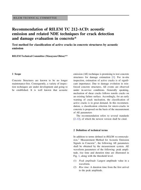
1 Scope<br />
Concrete Structures are known to be no longer<br />
maintenance-free. Consequently, a variety of inspection<br />
<strong>techniques</strong> are under development <strong>and</strong> going to<br />
be established. It is well known that <strong>acoustic</strong><br />
*The text presented hereafter is a draft <strong>for</strong> general<br />
consideration.<br />
Comments should be sent within 6 months of publication to the<br />
TC chairman, Prof. Masayasu Ohtsu, Graduate School<br />
of Science <strong>and</strong> Technology, Kumamoto University,<br />
2-39-1 Kurokami, Kumamoto 860-8555, Japan.<br />
Phone: ?81-96-342-3542, Fax: ?81-96-3423507,<br />
E-mail: Ohtsu@gpo.kumamoto-u.ac.jp.<br />
**This recommendation was developed by a work group<br />
within RILEM TC212-ACD under the leadership<br />
of Mr. Masayasu Ohtsu, Japan.<br />
TC-Membership:<br />
Chairman: Masayasu Ohtsu, Japan<br />
Secretary: Tomoki Shiotani, Japan<br />
Members: M. Shigeishi, T. Kamada, S. Yuyama, T. Watanabe,<br />
T. Suzuki, Japan; J. G. M. van Mier, T. Vogel, Switzerl<strong>and</strong>;<br />
C. Grosse, R. Helmerich, Germany; M. C. Forde, U.K.;<br />
A. Moczko, Pol<strong>and</strong>; D. Breysse, France; S. A. Ivanovich;<br />
Russia; A. Sajna, Slovenia; D. Aggelis, Greece;<br />
G. Lacidogna; Italy.<br />
RILEM Technical Committee 212-ACD<br />
(Masayasu Ohtsu) (&)<br />
Kumamoto University, Kurokami 2-39-1,<br />
Kumamoto 860-8555, Japan<br />
e-mail: Ohtsu@gpo.kumamoto-u.ac.jp<br />
<strong>emission</strong> (AE) technique is promising to test concrete<br />
structures <strong>for</strong> damage estimation [1]. For in-situ<br />
inspection, estimation of active <strong>crack</strong>s is of significant<br />
importance. Due to damage evolution in rein<strong>for</strong>ced<br />
concrete structures, AE events are observed<br />
under in-service conditions. Generally speaking,<br />
nucleation of shear <strong>crack</strong>s follows tensile <strong>crack</strong>s on<br />
an existing failure surface. Accordingly, <strong>for</strong> an early<br />
warning of <strong>crack</strong> nucleation, the classification of<br />
active <strong>crack</strong>s is in great dem<strong>and</strong>. In this recommendation,<br />
a classification criterion <strong>for</strong> micro-<strong>crack</strong>s in<br />
concrete is proposed on the basis of the measurement<br />
of AE parameters<br />
The recommendation refers to several st<strong>and</strong>ards<br />
[2–12], of which the newest version shall be cited.<br />
2 Definition of technical terms<br />
In addition to terms defined in RILEM recommendation,’’<br />
Measurement Method <strong>for</strong> Acoustic Emission<br />
Signals in Concrete’’, the following AE parameters<br />
shall be obtained by the measurement system. AE<br />
wave<strong>for</strong>m parameters of the following: peak amplitude,<br />
rise time <strong>and</strong> duration time are illustrated in<br />
Fig. 1, along with the threshold level.<br />
(1) Peak amplitude: Largest amplitude value in a<br />
wave<strong>for</strong>m.<br />
(2) Rise time: A duration time from the first arrival<br />
to the peak amplitude.
1188 Materials <strong>and</strong> Structures (2010) 43:1187–1189<br />
Fig. 1 AE wave<strong>for</strong>m parameters<br />
(3) Duration time: Duration observed from the first<br />
arrival to the time when the amplitude decays<br />
up to the level lower than the threshold.<br />
(4) Counts: Normally, AE counts imply number of<br />
times the signal amplitude exceeds the threshold.<br />
They also are rigorously named ring-down counts.<br />
(5) External parameters: The measurement system<br />
shall be able to obtain time in<strong>for</strong>mation along<br />
with AE parameters. In addition, such external<br />
parameters as load, strain <strong>and</strong> so <strong>for</strong>th are<br />
preferably recorded in the system.<br />
3 Measurement system<br />
3.1 AE sensor<br />
AE sensors shall be calibrated properly in advance of<br />
the measurement. AE sensor is sensitive enough to<br />
detect AE signals generated in a concrete structure,<br />
taking <strong>acoustic</strong> coupling into consideration. AE<br />
sensor is also robust enough against temperature<br />
change, moisture condition <strong>and</strong> mechanical vibrations<br />
in the environments.<br />
For the parameter analysis, a broad-b<strong>and</strong> sensor is<br />
recommended. But, resonance-type sensors are also<br />
available, in the case that their resonance frequencies<br />
are higher than 60 kHz in concrete. So far, resonant<br />
frequencies of resonance-type sensors have been<br />
applied to concrete in the range of 50–250 kHz.<br />
3.2 System <strong>for</strong> signal analysis<br />
The system of AE devices shall be specified, depending<br />
on the target. AE sensors are attached at proper locations<br />
to cover the target area. The internal noise of the<br />
amplifier shall be inherently low <strong>and</strong> less than 20 lV<br />
(26dB<strong>for</strong>0dB= 1 lV) as the peak voltage converted<br />
by input voltage. The amplifier shall be robust enough<br />
against the environmental conditions <strong>and</strong> be protected<br />
properly. The frequency range shall be determined prior<br />
to the measurement, taking into account the per<strong>for</strong>mance<br />
of AE sensor <strong>and</strong> the amplifier. The range from<br />
several kHz to several 100 kHz is recommended in<br />
concrete. The period of the measurement shall be<br />
prescribed, depending on propagation property of AE<br />
signals in the target structure.<br />
4 Environmental noises<br />
In advance to AE measurement, the noise level shall be<br />
estimated. Then, counteract against external noises,<br />
wind, rain, sunshine <strong>and</strong> so <strong>for</strong>th shall be conducted to<br />
decrease the noise level as low as possible. In the case<br />
that the noises have similar frequency contents,<br />
amplitudes to AE signals or sources of the noises are<br />
unknown, characteristics of the noises shall be estimated<br />
prior to the measurement. Based on this result,<br />
separation of AE signals from the noises shall be<br />
achieved. In this respect, the use of filters is applicable<br />
after determining the proper frequency range.<br />
Sensitivity of AE channels shall be conducted<br />
routinely by employing the st<strong>and</strong>ard source. Variation<br />
within the channels shall be less than 3%.<br />
5 Test procedure<br />
AE signals due to <strong>crack</strong>ing shall be detected properly<br />
<strong>for</strong> the duration of the measurement. The test shall be<br />
conducted under loads which must not fundamentally<br />
make any critical damage on functions of the<br />
structure to detect <strong>and</strong> locate active <strong>crack</strong>s. In<br />
advance to the test, attenuation properties of the<br />
target structure shall be estimated, by employing the<br />
st<strong>and</strong>ard source or the equivalent.<br />
From AE parameters of the rise time <strong>and</strong> the peak<br />
amplitude in Fig. 1, the RA value defined as,<br />
RA ¼ the rise time=the peak amplitude ð1Þ<br />
shall be calculated.<br />
The averaged frequency Fa of each wave<strong>for</strong>m<br />
shall be calculated from,<br />
Average frequency ðFaÞ ¼AE ringdown counts=<br />
the duration time ð2Þ
Materials <strong>and</strong> Structures (2010) 43:1187–1189 1189<br />
Fig. 2 Qualification of the damage by AE parameters<br />
where the definitions of AE ring-down counts <strong>and</strong> the<br />
duration time are given in RILEM recommendation<br />
mentioned above.<br />
By applying these parameters, classification of<br />
<strong>crack</strong>s into tensile <strong>crack</strong>s <strong>and</strong> other-type <strong>crack</strong>s<br />
including shear <strong>crack</strong>s is per<strong>for</strong>med as shown in<br />
Fig. 2, where RA values <strong>and</strong> average frequencies<br />
plotted shall be calculated from the moving average<br />
of more than 50 hits. It is noted that the RA values<br />
may vary depending on the threshold level. But, the<br />
selection of AE sensors does not provide much effect<br />
on the results as shown in the figure.<br />
For plotting data, the ordinate is shown by physical<br />
unit of kHz <strong>and</strong> the abscissa scale is msec/volt, where<br />
the amplitude shall be calibrated as the sensor output,<br />
compensating the effect of amplifiers. In the figure,<br />
the ratio of the abscissa scale to the ordinate scale is<br />
set to 10. But, it just means a suggestive value. A<br />
proper ratio shall be determined, depending on<br />
materials <strong>and</strong> structures. It is recommended to set<br />
the ratio in advance to the classification of active<br />
<strong>crack</strong>s. In a reference, it is recommended to apply the<br />
ratio of 50, based on the moment tensor analysis [13].<br />
In another reference, just a trend of these two indices<br />
(1) <strong>and</strong> (2) is applied to identify the corrosion process<br />
in rein<strong>for</strong>ced concrete [14], <strong>and</strong> to characterize the<br />
transition from tensile to shear <strong>crack</strong>ing in steel-fiber<br />
rein<strong>for</strong>ced concrete [15].<br />
6 Documents<br />
Documents to report the results shall contain the<br />
following articles:<br />
(a) Date<br />
(b) Test person<br />
(c) Devices<br />
(d) Measurement locations<br />
(e) Results of system inspection be<strong>for</strong>e <strong>and</strong> after the<br />
setup<br />
(f) Results<br />
References<br />
1. Grosse CU, Ohtsu M (eds) (2008) Acoustic <strong>emission</strong><br />
testing. Springer, 2008<br />
2. European Norms: EN1330-9 Nondestructive testing—terminology-Part<br />
9: terms used in AE testing<br />
3. EN 13554 Nondestructive testing-Acoustic <strong>emission</strong>-General<br />
principles<br />
4. American Society <strong>for</strong> Testing <strong>and</strong> Materials (ASTM)<br />
E1316 St<strong>and</strong>ard Definitions of Terms relating to AE<br />
5. ASTM E650 St<strong>and</strong>ard Guide <strong>for</strong> Mounting Piezoelectric<br />
AE Sensors<br />
6. ASTM E750 St<strong>and</strong>ard Practice <strong>for</strong> Characterizing AE<br />
Instrumentation<br />
7. American Society <strong>for</strong> Nondestructive Testing (ASNT)<br />
DGZfP-SE1 nondestructive testing: <strong>acoustic</strong> <strong>emission</strong><br />
terms<br />
8. ASNT DGZfP-SE3 Guide line <strong>for</strong> AE Characterization<br />
during AE Test<br />
9. French Association <strong>for</strong> St<strong>and</strong>ards (AFNOR) NF A09-350<br />
nondestructive testing-vocabulary used in <strong>acoustic</strong><br />
<strong>emission</strong><br />
10. European Working Group on Acoustic Emission (EW-<br />
GAE) Codes <strong>for</strong> AE examination: code I-location of discrete<br />
<strong>acoustic</strong> events<br />
11. EWGAE Codes <strong>for</strong> AE Examination: code IV-definition of<br />
terms in AE<br />
12. Japanese Society <strong>for</strong> Nondestructive Inspection (JSNDI)<br />
NDIS 2421 Recommendation practice <strong>for</strong> in situ monitoring<br />
AE of concrete structures by AE<br />
13. Ohno K, Ohtsu M (2008) Comparison of <strong>crack</strong> classification<br />
in concrete by parameter analysis <strong>and</strong> SiGMA in<br />
<strong>acoustic</strong> <strong>emission</strong>, Proc. structural faults <strong>and</strong> repair 2008,<br />
12th international conference <strong>and</strong> exhibition. Edinburgh,<br />
UK (CD-ROM)<br />
14. Ohtsu M, Tomoda Y (2008) Phenomenological model of<br />
corrosion process in rein<strong>for</strong>ced concrete identified by<br />
<strong>acoustic</strong> <strong>emission</strong>. ACI Mater J 105(2):194–199<br />
15. Soulioti D, Barkoula NM, Paipetis A, Matikas TE, Shiotani<br />
T, Aggelis DG (2009) Acoustic <strong>emission</strong> behavior of steel<br />
fiber rein<strong>for</strong>ced concrete under bending. Construct Build<br />
Mater 23:3532–3536