SHARP TROUBLE & ERROR CODES AR-651, AR-810 - OlsonBros
SHARP TROUBLE & ERROR CODES AR-651, AR-810 - OlsonBros
SHARP TROUBLE & ERROR CODES AR-651, AR-810 - OlsonBros

You also want an ePaper? Increase the reach of your titles
YUMPU automatically turns print PDFs into web optimized ePapers that Google loves.
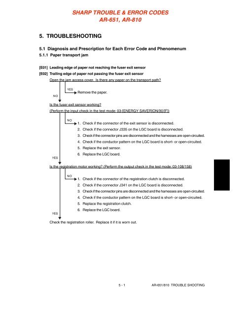
5. <strong>TROUBLE</strong>SHOOTING<br />
5.1 Diagnosis and Prescription for Each Error Code and Phenomenum<br />
5.1.1 Paper transport jam<br />
[E01] Leading edge of paper not reaching the fuser exit sensor<br />
[E02] Trailing edge of paper not passing the fuser exit sensor<br />
Open the jam access cover. Is there any paper on the transport path?<br />
NO<br />
YES<br />
Remove the paper.<br />
Is the fuser exit sensor working?<br />
(Perform the input check in the test mode: 03-[ENERGY SAVER]ON/[6]/[F])<br />
YES<br />
NO<br />
1. Check if the connector of the exit sensor is disconnected.<br />
2. Check if the connector J335 on the LGC board is disconnected.<br />
3. Check if the connector pins are disconnected and the harnesses are open-circuited.<br />
4. Check if the conductor pattern on the LGC board is short- or open-circuited.<br />
5. Replace the exit sensor.<br />
6. Replace the LGC board.<br />
Is the registration motor working? (Perform the output check in the test mode: 03-108/158)<br />
YES<br />
NO<br />
1. Check if the connector of the registration clutch is disconnected.<br />
2. Check if the connector J341 on the LGC board is disconnected.<br />
3. Check if the connector pins are disconnected and the harnesses are open-circuited.<br />
4. Check if the conductor pattern on the LGC board is short- or open-circuited.<br />
5. Replace the registration clutch.<br />
6. Replace the LGC board.<br />
Check the registration roller. Replace it if it is worn out.<br />
5 - 1 <strong>AR</strong>-<strong>651</strong>/<strong>810</strong> <strong>TROUBLE</strong> SHOOTING
[E03] Paper remaining inside the copier at power ON<br />
Open the cover of the unit/area whose picture is flashing on the control panel. Is there any paper on<br />
the transport path? (Refer to the following table)<br />
NO<br />
YES<br />
Remove the paper.<br />
Is the sensor in the jamming area working?<br />
(Perform the input check in the test mode: refer to the following table.)<br />
YES<br />
NO<br />
Replace the LGC board.<br />
1. Check if the connector of the sensor is disconnected.<br />
2. Check if any of the connectors on the LGC board is disconnected.<br />
3. Check if the connector pins are disconnected and the harnesses are open-circuited.<br />
4. Check if the conductor pattern on the LGC board is short- or open-circuited.<br />
5. Replace the sensor.<br />
6. Replace the LGC board.<br />
Relation between the jamming area and the corresponding sensors<br />
Jamming area Sensor Test mode/Input check<br />
Registration area Registration sensor 03-[ENERGY SAVER]ON/[4][E]<br />
Exit/Reverse area Exit sensor 03-[ENERGY SAVER]OFF/[6][G]<br />
<strong>AR</strong>-<strong>651</strong>/<strong>810</strong> <strong>TROUBLE</strong> SHOOTING 5 - 2<br />
Reversel sensor 1 03-[ENERGY SAVER]OFF/[6][C]<br />
Reversel sensor 2 03-[ENERGY SAVER]OFF/[6][B]<br />
Reverse transport Transport sensor 1 03-[ENERGY SAVER]OFF/[0][C]<br />
area Transport sensor 2 03-[ENERGY SAVER]OFF/[0][A]<br />
Transport sensor 3 03-[ENERGY SAVER]OFF/[0][B]<br />
Paper feeding area 1st cassette feed sensor 03-[ENERGY SAVER]OFF/[2][A]<br />
2nd cassette feed sensor 03-[ENERGY SAVER]OFF/[3][A]<br />
3rd cassette/Tandem LCF feed sensor 03-[ENERGY SAVER]OFF/[4][A]<br />
4th cassette/Tandem LCF feed sensor 03-[ENERGY SAVER]OFF/[5][A]<br />
1st cassette transport sensor 03-[ENERGY SAVER]OFF/[2][B]<br />
2nd cassette transport sensor 03-[ENERGY SAVER]OFF/[3][B]<br />
3rd cassette/Tandem LCF transport 03-[ENERGY SAVER]OFF/[4][B]<br />
sensor<br />
4th cassette/Tandem LCF transport 03-[ENERGY SAVER]OFF/[5][B]<br />
sensor
[E09] Jam caused by an abnormal HDD<br />
(1) Check if the connectors of the HDD are disconnected.<br />
(2) Check if the connector pins are disconnected and the harnesses are open-circuited.<br />
(3) Replace the HDD.<br />
(4) Replace the SYS board.<br />
[E20] Paper fed from the 1st cassette not reaching the registration sensor<br />
Open the jam access cover. Is there any paper in front of the registration sensor?<br />
NO<br />
YES<br />
Remove the paper.<br />
Is the registration sensor working?<br />
(Perform the input check in the test mode: 03-[ENERGY SAVER]ON/[4]/[E])<br />
YES<br />
NO<br />
1. Check if the connector of the registration sensor is disconnected.<br />
2. Check if the connector J341 on the LGC board is disconnected.<br />
3. Check if the connector pins are disconnected and the harnesses are open-circuited.<br />
4. Check if the conductor pattern on the LGC board is short- or open-circuited.<br />
5. Replace the registration sensor.<br />
6. Replace the LGC board.<br />
Is the 1st cassette feed clutch working?<br />
(Perform the output check in the test mode: 03-201)<br />
YES<br />
NO<br />
1. Check if the connector of the 1st cassette feed clutch is disconnected.<br />
2. Check if the connector J329 on the LGC board is disconnected.<br />
3. Check if the connector pins are disconnected and the harnesses are open-circuited.<br />
4. Check if the conductor pattern on the LGC board for short- or open-circuited.<br />
5. Replace the upper cassette feed clutch.<br />
6. Replace the LGC board.<br />
Check the 1st cassette feed roller and separation roller. Replace them if they are worn out.<br />
5 - 3 <strong>AR</strong>-<strong>651</strong>/<strong>810</strong> <strong>TROUBLE</strong> SHOOTING
[E22] Paper fed from the 2nd cassette not reaching the registration sensor<br />
[E30] Paper fed from the 3rd cassette not reaching the registration sensor<br />
[E34] Paper fed from the 4th cassette not reaching the registration sensor<br />
[E3C] Paper fed from the tandem LCF not reaching the registration sensor<br />
Open the bypass unit cover. Is there paper in front of the registration sensor?<br />
NO<br />
YES<br />
Remove the paper.<br />
Is the registration sensor working?<br />
(Perform the input check in the test mode: 03-[ENERGY SAVER]ON/[4]/[E]<br />
YES<br />
NO<br />
1. Check if the connector of the registration sensor is disconnected.<br />
2. Check if the connector J341 on the LGC board is disconnected.<br />
3. Check if the connector pins are disconnected and the harnesses are open-circuited.<br />
4. Check if the conductor pattern on the LGC board is short- or open-circuited.<br />
5. Replace the registration sensor.<br />
6. Replace the LGC board.<br />
Are the transport clutches working? (Perform the output check in the test mode: 03-202, 203, 210)<br />
YES<br />
NO<br />
1. Check if the connectors of the transport clutches are disconnected.<br />
2. Check if the connector J328, 329, 350 on the LGC board is disconnected.<br />
3. Check if the connector pins are disconnected and the harnesses are open-circuited.<br />
4. Check if the conductor pattern on the LGC board is short- or open-circuited.<br />
5. Replace the transport clutches.<br />
6. Replace the LGC board.<br />
Check the transport roller. Replace it if it is worn out.<br />
<strong>AR</strong>-<strong>651</strong>/<strong>810</strong> <strong>TROUBLE</strong> SHOOTING 5 - 4
[E25] External LCF transport jam (paper not reaching the registration sensor)<br />
Is there any paper before the registration sensor when the bypass unit cover is opened?<br />
NO<br />
Remove the paper.<br />
Is the registration sensor working? (Perform the input check in the test mode: 03-[ENERGY<br />
SAVER]ON/[4]/[E])<br />
YES<br />
1. Check if the registration connector is not disconnected.<br />
2. Check if the connector J341 on the LGC board is not disconnected.<br />
3. Check if the connector pins are not disconnected and the harness is not<br />
open-circuited.<br />
4. Check if the conductor pattern on the LGC board is not short- or open-<br />
circuited.<br />
5. Replace the registration sensor.<br />
6. Replace the LGC board.<br />
Is the external LCF transport motor driving? (Perform the output check in the test mode: 03-122/172)<br />
YES<br />
1. Check if the connector of the transport motor is not disconnected.<br />
2. Check if the connectors J801~804 on the LCF board are not disconnected.<br />
3. Check if there is any abnormality at the transort drive unit.<br />
Is the external LCF feed clutch working? (Perform the output check in the test mode: 03-272)<br />
YES<br />
YES<br />
NO<br />
NO<br />
NO<br />
1. Check if the external LCF clutch connector is not disconnected.<br />
2. Check if the connectors J801~804 on the LCF board are not disconnected.<br />
3. Check if the connector J346 on the LGC board is not disconnected.<br />
4. Check if the connector pins are not disconnected and the harness is<br />
not open-circuited.<br />
5. Check if the conductor pattern on the LCF and LGC boards is not<br />
short- or open-circuited.<br />
6. Replace the external LCF feed clutch.<br />
7. Replace the LCF board.<br />
8. Replace the LGC board.<br />
5 - 5 <strong>AR</strong>-<strong>651</strong>/<strong>810</strong> <strong>TROUBLE</strong> SHOOTING
Is the external LCF transport clutch working? (Perform the output check in the test mode: 03-273)<br />
YES<br />
NO<br />
1. Check if the connector of the external LCF feed clutch is not disconnected.<br />
2. Check if the connectors J801~804 on the LCF board are not disconnected.<br />
3. Check if the connector J346 on the LGC board is not disconnected.<br />
4. Check if the connector pins are not disconnected and the harness is not<br />
open-circuited.<br />
5. Check if the conductor pattern on the LCF and LGC boards is not short- or<br />
open-circuited.<br />
6. Replace the external LCF feed clutch.<br />
7. Replace the LCF board.<br />
8. Replace the LGC board.<br />
1. Check if there is any abnormality at the transport drive unit.<br />
2. Check the condition of the external LCF feed roller and separation roller and clean them, or if<br />
they are deteriorated, replace them.<br />
<strong>AR</strong>-<strong>651</strong>/<strong>810</strong> <strong>TROUBLE</strong> SHOOTING 5 - 6
[E21] Paper fed from the 1st cassette not reaching the 1st casette transport sensor<br />
[E23] Paper fed from the 2nd cassette not reaching the 1st casette transport sensor<br />
[E31] Paper fed from the 3rd cassette not reaching the 1st casette transport sensor<br />
[E35] Paper fed from the 4th cassette not reaching the 1st casette transport sensor<br />
[E3D] Paper fed from the tandem LCF not reaching the 1st casette transport sensor<br />
Open the feed cover. Is there paper in front of the 1st cassette transport sensor?<br />
NO<br />
YES<br />
Remove the paper.<br />
Is the 1st cassette transport sensor working?<br />
(Perform the input check in the test mode: 03-[ENERGY SAVER]OFF/[2]/[B])<br />
YES<br />
NO<br />
1. Check if the connector of the 1st cassette transport sensor is disconnected.<br />
2. Check if the connector J328, 329,350 on the LGC board is disconnected.<br />
3. Check if the connector pins are disconnected and the harnesses are open-circuited.<br />
4. Check if the conductor pattern on the LGC board is short- or open-circuited.<br />
5. Replace the 1st cassette transport sensor.<br />
6. Replace the LGC board.<br />
Are the transport clutches working? (Perform the output check in the test mode:<br />
03-202, 203, 210)<br />
YES<br />
NO<br />
1. Check if the connectors of the transport clutches are disconnected.<br />
2. Check if the connector J328, 329, 350 on the LGC board is disconnected.<br />
3. Check if the connector pins are disconnected and the harnesses are open-circuited.<br />
4. Check if the conductor pattern on the LGC board is short- or open-circuited.<br />
5. Replace the transport clutches.<br />
6. Replace the LGC board.<br />
Check the transport roller. Replace it if it is worn out.<br />
5 - 7 <strong>AR</strong>-<strong>651</strong>/<strong>810</strong> <strong>TROUBLE</strong> SHOOTING
[E24] Paper fed from the 2nd cassette not reading the 2nd cassette transport sensor<br />
[E32] Paper fed from the 3rd cassette not reaching the 2nd cassette transport sensor<br />
[E35] Paper fed from the 4th cassette not reaching the 2nd cassette transport sensor<br />
[E3E] Paper fed from the tandem LCF not reaching the 2nd cassette transport sensor<br />
Open the feed cover. Is there paper in front of the 2nd cassette transport sensor?<br />
NO<br />
YES<br />
Remove the paper.<br />
Is the 2nd cassette transport sensor working?<br />
(Perform the input check in the test mode: 03-[ENERGY SAVER]OFF/[3]/[B])<br />
YES<br />
NO<br />
1. Check if the connector of the 2nd cassette transport sensor is disconnected.<br />
2. Check if the connector J328,329,350 on the LGC board is disconnected.<br />
3. Check if the connector pins are disconnected and the harnesses are open-circuited.<br />
4. Check if the conductor pattern on the LGC board is short- or open-circuited.<br />
5. Replace the 2nd cassette transport sensor.<br />
6. Replace the LGC board.<br />
Are the transport clutches working? (Perform the output check in the test mode: 03-203, 210, 226)<br />
YES<br />
NO<br />
1. Check if the connectors of the transport clutches are disconnected.<br />
2. Check if the connector J328, 329, 350 on the LGC board is disconnected.<br />
3. Check if the connector pins are disconnected and the harnesses are open-circuited.<br />
4. Check if the conductor pattern on the LGC board is short- or open-circuited.<br />
5. Replace the transport clutches.<br />
6. Replace the LGC board.<br />
Check the transport roller. Replace it if it is worn out.<br />
<strong>AR</strong>-<strong>651</strong>/<strong>810</strong> <strong>TROUBLE</strong> SHOOTING 5 - 8
[E33] Paper fed from the 3rd cassette not reaching the 3rd cassette transport sensor<br />
[E37] Paper fed from the 4th cassette not reaching the 3rd cassette transport sensor<br />
Open the feed cover. Is there any paper in front of the 3rd cassette transport sensor?<br />
NO<br />
YES<br />
Remove the paper.<br />
Is the 3rd cassette tranport sensor working?<br />
(Perform the input check in the test mode: 03-[ENERGY SAVER]OFF/[4]/[B]<br />
YES<br />
NO<br />
1. Check if the connector of the 3rd cassette transport sensor is disconnected.<br />
2. Check if the connector J328 on the LGC board is disconnected.<br />
3. Check if the connector pins are disconnected and the harnesses are open-circuited.<br />
4. Check if the conductor patterns on the LGC board are short- or open-circuited.<br />
5 Replace the 3rd cassette transport sensor.<br />
6. Replace the LGC board.<br />
Is the transport clutch working? (Perform the output check in the test mode: 03-225)<br />
YES<br />
NO<br />
1. Check if the connector of the transport clutch is disconnected.<br />
2. Check if the connector J328, 329, 350 on the LGC board is disconnected.<br />
3. Check if the connector pins are disconnected and the harnesses are open-circuited.<br />
4. Check if the conductor patterns on the LGC board are short- or open-circuited.<br />
5 Replace the transport clutch.<br />
6 Replace the LGC board.<br />
Check the transport roller. Replace it if it is worn out.<br />
5 - 9 <strong>AR</strong>-<strong>651</strong>/<strong>810</strong> <strong>TROUBLE</strong> SHOOTING
[E38] Paper fed from the 4th cassette not reaching the 4th cassette transport sensor<br />
Open the feed cover. Is there any paper in front of the 4th cassette transport sensor?<br />
NO<br />
YES<br />
Remove the paper.<br />
Is the 4th cassette transport sensor working?<br />
(Perform the input check in the test mode: 03-[ENERGY SAVER]OFF/[5]/[B]<br />
YES<br />
NO<br />
1. Check if the connector of the 4th cassette transport sensor is disconnected.<br />
2. Check if the connector J350 on the LGC board is disconnected.<br />
3. Check if the connector pins are disconnected and the harnesses are open-circuited.<br />
4. Check if the conductor patterns on the LGC board are short- or open-circuited.<br />
5 Replace the 4th cassette transport sensor.<br />
6. Replace the LGC board.<br />
Is the transport clutch working? (Perform the output check in the test mode: 03-225)<br />
YES<br />
NO<br />
1. Check if the connector of the PFP transport clutch is disconnected.<br />
2. Check if the connector J350 on the LGC board is disconnected.<br />
3. Check if the connector pins are disconnected and the harnesses are open-circuited.<br />
4. Check if the conductor patterns on the LGC board are short- or open-circuited.<br />
5 Replace the transport clutch.<br />
6 Replace the LGC board.<br />
Check the transport roller. Replace it if it is worn out.<br />
<strong>AR</strong>-<strong>651</strong>/<strong>810</strong> <strong>TROUBLE</strong> SHOOTING 5 - 10
[E3F] Paper fed from the tandem LCF not reading the tandem LCF transport sensor<br />
Open the feed cover. Is there paper in front of the tandem LCF transport sensor?<br />
NO<br />
YES<br />
Remove the paper.<br />
Is the tandem LCF transport sensor working?<br />
(Perform the input check in the test mode: 03-[ENERGY SAVER]OFF/[4]/[B])<br />
YES<br />
NO<br />
1. Check if the connector of the tandem LCF transport sensor is disconnected.<br />
2. Check if the connector J328, 350 on the LGC board is disconnected.<br />
3. Check if the connector pins are disconnected and the harnesses are open-circuited.<br />
4. Check if the conductor pattern on the LGC board is short- or open-circuited.<br />
5. Replace the tandem LCF transport sensor.<br />
6. Replace the LGC board.<br />
Are the transport clutches working? (Perform the output check in the test mode: 03-225)<br />
YES<br />
NO<br />
1. Check if the connectors of the transport clutches are disconnected.<br />
2. Check if the connector J328, 350 on the LGC board is disconnected.<br />
3. Check if the connector pins are disconnected and the harnesses are open-circuited.<br />
4. Check if the conductor pattern on the LGC board is short- or open-circuited.<br />
5. Replace the transport clutches.<br />
6. Replace the LGC board.<br />
Check the transport roller. Replace it if it is worn out.<br />
5 - 11 <strong>AR</strong>-<strong>651</strong>/<strong>810</strong> <strong>TROUBLE</strong> SHOOTING
[EB5] Paper left on the transport path<br />
In case an paper is fed from the 1st cassette, bypass feed unit or reversed paper transport section:<br />
Open the bypass unit cover. Is there any paper in front of the registration sensor?<br />
NO<br />
YES<br />
Remove the paper.<br />
Is the registration sensor working?<br />
(Perform the input check in the test mode: 03-[ENERGY SAVER]ON/[4]/[E)<br />
YES<br />
NO<br />
1. Check if the connector of the registration sensor is disconnected.<br />
2. Check if the connector J341 on the LGC board is disconnected.<br />
3. Check if the connector pins are disconnected and the harnesses are open-circuited.<br />
4. Check if the conductor pattern on the LGC board is short- or open-circuited.<br />
5. Replace the registration sensor.<br />
6. Replace the LGC board.<br />
Check the rollers. Replace them if they are worn out.<br />
In case an paper is fed from the 2nd, 3rd, 4th or tandem LCF:<br />
Open the feed cover. Is there any paper in front of the 1st cassette transport sensor?<br />
NO<br />
YES<br />
Remove the paper.<br />
Is the 1st cassette transport sensor working?<br />
(Perform the input check in the test mode: 03-[ENERGY SAVER]OFF/[2]/[B])<br />
YES<br />
NO<br />
1. Check if the connector of the 1st cassette transport sensor is disconnected.<br />
2. Check if the connector J329 on the LGC board is disconnected.<br />
3. Check if the connector pins are disconnected and the harnesses are open-circuited.<br />
4. Check if the conductor pattern on the LGC board is short- or open-circuited.<br />
5. Replace the 1st cassette transport sensor.<br />
6. Replace the LGC board.<br />
Check the rollers. Replace them if they are worn out.<br />
<strong>AR</strong>-<strong>651</strong>/<strong>810</strong> <strong>TROUBLE</strong> SHOOTING 5 - 12
[EB6] Paper left on the transport path<br />
Open the bypass unit cover. Is there any paper in front of the registration sensor?<br />
NO<br />
YES<br />
Remove the paper.<br />
Is the registration sensor working?<br />
(Perform the input check in the test mode: 03-[ENERGY SAVER]ON/[4]/[E)<br />
YES<br />
NO<br />
1. Check if the connector of the registration sensor is disconnected.<br />
2. Check if the connector J341 on the LGC board is disconnected.<br />
3. Check if the connector pins are disconnected and the harnesses are open-circuited.<br />
4. Check if the conductor pattern on the LGC board is short- or open-circuited.<br />
5. Replace the registration sensor.<br />
6. Replace the LGC board.<br />
Check the rollers. Replace them if they are worn out.<br />
5 - 13 <strong>AR</strong>-<strong>651</strong>/<strong>810</strong> <strong>TROUBLE</strong> SHOOTING
5.1.2 Paper misfeeding<br />
[E11] Misfeeding during duplex printing (paper not reaching the registration sensor)<br />
Open the bypass unit cover. Is there any paper in front of the registration sensor?<br />
NO<br />
YES<br />
Remove the paper.<br />
Is the registration sensor working?<br />
(Perform the input check in the test mode:03-[ENERGY SAVER]ON/[4]/[E])<br />
YES<br />
NO<br />
1. Check if the connector of the registration sensor is disconnected.<br />
2. Check if the connector J341 on the LGC board is disconnected.<br />
3. Check if the connector pins are disconnected and the harnesses are open-circuited.<br />
4. Check if the conductor pattern on the LGC board is short- or open-circuited.<br />
5. Replace the registration sensor.<br />
6. Replace the LGC board.<br />
Is the reversed paper transport cluch working?<br />
(Perform the output check in the test mode: 03-220, 221)<br />
YES<br />
NO<br />
1. Check if the connector of the reversed paper transport clutch is disconnected.<br />
2. Check if the connector J334 on the LGC board is disconnected.<br />
3. Check if the connector pins are disconnected and the harnesses are open-circuited.<br />
4. Check if the conductor pattern on the LGC board is short- or open-circuited.<br />
5. Replace the reversed paper transport clutch.<br />
6. Replace the LGC board.<br />
Check the rollers in the reversed papaer transport section. Replace them if they are worn out.<br />
<strong>AR</strong>-<strong>651</strong>/<strong>810</strong> <strong>TROUBLE</strong> SHOOTING 5 - 14
[E12] Bypass misfeeding (paper not reaching the registration sensor)<br />
Open the bypass unit cover. Is there any paper in front of the registration sensor?<br />
NO<br />
YES<br />
Remove the paper.<br />
Is the registration sensor working?<br />
(Perform the input check in the test mode: 03-[ENERGY SAVER]ON/[4]/[E])<br />
YES<br />
NO<br />
1. Check if the connector of the registration sensor is disconnected.<br />
2. Check if the connector J341 on the LGC board is disconnected.<br />
3. Check if the connector pins are disconnected and the harnesses are open-circuited.<br />
4. Check if the conductor pattern on the LGC board is short- or open-circuited.<br />
5. Replace the registration sensor.<br />
6. Replace the LGC board.<br />
Is the bypass feed clutch working? (Perform the output check in the test mode: 03-204)<br />
YES<br />
NO<br />
1. Check if the connector of the bypass feed clutch is disconnected.<br />
2. Check if the connector J327 on the LGC board is disconnected.<br />
3. Check if the connector pins are disconnected and the harnesses are open-circuited.<br />
4. Check if the conductor pattern on the LGC board is short- or open-circuited.<br />
5. Replace the bypass feed clutch.<br />
6. Replace the LGC board.<br />
Check the bypass feed roller and separation roller. Replace them if they are worn out.<br />
5 - 15 <strong>AR</strong>-<strong>651</strong>/<strong>810</strong> <strong>TROUBLE</strong> SHOOTING
[E13] 1st cassette misfeeding (paper not reaching the 1st cassette feed sensor)<br />
Open the feed cover. Is there any paper in front of the 1st cassette feed sensor?<br />
NO<br />
YES<br />
Remove the paper.<br />
Is the 1st cassetter feed sensor working?<br />
(Perform the input check in the test mode: 03-[ENERGY SAVER]OFF/[2]/[B])<br />
YES<br />
NO<br />
1. Check if the connector of the 1st cassette feed sensor is disconnected.<br />
2. Check if the connector J329 on the LGC board is disconencted.<br />
3. Check if the connector pins are disconnected and the harnesses are open-circuited.<br />
4. Check if the conductor pattern on the LGC board is short- or open-circuited.<br />
5. Replace the 1st cassette feed sensor.<br />
6. Replace the LGC board.<br />
Is the 1st cassette feed clutch working?<br />
(Perform the output check in the test mode: 03-201)<br />
YES<br />
NO<br />
1. Check if the connector of the 1st cassette feed clutch is disconnected.<br />
2. Check if the connector J329 on the LGC board is disconnected.<br />
3. Check if the connector pins are disconnected and the harnesses are open-<br />
circuited.<br />
4. Check if the conductor pattern on the LGC board is short- or open-circuited.<br />
5. Replace the 1st cassette feed clutch.<br />
6. Replace the LGC board.<br />
Check the 1st cassette feed roller and separation roller. Replace them if they are worn out.<br />
<strong>AR</strong>-<strong>651</strong>/<strong>810</strong> <strong>TROUBLE</strong> SHOOTING 5 - 16
[E14] 2nd cassette misfeeding (paper not reaching the 2nd cassette feed sensor)<br />
Open the feed cover. Is there any paper in front of the 2nd cassette feed sensor?<br />
NO<br />
YES<br />
Remove the paper.<br />
Is the 2nd cassette feed sensor working?<br />
(Perform the input check in the test mode: 03-[ENERGY SAVER]OFF/[3]/[B])<br />
YES<br />
NO<br />
1. Check if the connector of the 2nd cassette feed sensor is disconnected.<br />
2. Check if the connector J329 on the LGC board is disconnected.<br />
3. Check if the connector pins are disconnected and the harnesses are open-circuited.<br />
4. Check if the conductor pattern on the LGC board is short- or open-circuited.<br />
5. Replace the 2nd cassette feed sensor.<br />
6. Replace the LGC board.<br />
Is the 2nd cassette feed clutch working?<br />
(Perform the output check in the test mode: 03-202)<br />
YES<br />
NO<br />
1. Check if the connector of the 2nd cassette feed clutch is disconnected.<br />
2. Check if the connector J329 on the LGC board is disconnected.<br />
3. Check if the connector pins are disconnected and the harnesses are open-<br />
circuited.<br />
4. Check if the conductor pattern on the LGC board is short- or open-circuited.<br />
5. Replace the 2nd cassette feed clutch.<br />
6. Replace the LGC board.<br />
Check the 2nd cassette feed roller and separation roller. Replace them if they are worn out.<br />
5 - 17 <strong>AR</strong>-<strong>651</strong>/<strong>810</strong> <strong>TROUBLE</strong> SHOOTING
[E15] 3rd cassette misfeeding (paper not reaching the 3rd cassette feed sensor)<br />
Open the feed cover. Is there any paper in front of the 3rd cassette feed sensor?<br />
YES<br />
Remove the paper.<br />
NO<br />
▼<br />
Is the 3rd cassette feed sensor working?<br />
(Perform the input check in the test mode: 03-[ENERGY SAVER]OFF/[4]/[B])<br />
YES<br />
NO<br />
1. Check if the connector of the 3rd cassette feed sensor is disconnected.<br />
2. Check if the connector J328 on the LGC board is disconnected.<br />
3. Check if the connector pins are disconnected and the harnesses are open-circuited.<br />
4. Check if the conductor patterns on the LGC board are short- or open-circuited.<br />
5. Replace the 3rd cassette feed sensor.<br />
6. Replace the LGC board.<br />
Is the 3rd cassette/tandem LCF feed clutch working? (Perform the output check in the test mode: 03-226)<br />
YES<br />
NO<br />
1. Check if the connector of the 3rd cassette/tandem LCF feed clutch is discon-<br />
nected.<br />
2. Check if the connector J328 on the LGC board is disconnected.<br />
3. Check if the connector pins are disconnected and the harnesses are open-circuited.<br />
4. Check if the conductor patterns on the LGC board are short- or open-circuited.<br />
5. Replace the 3rd cassette/tandem LCF feed clutch.<br />
6. Replace the LGC board.<br />
Check the 3rd cassette/tandem LCF feed roller and separation roller. Replace them if they are worn<br />
out.<br />
<strong>AR</strong>-<strong>651</strong>/<strong>810</strong> <strong>TROUBLE</strong> SHOOTING 5 - 18
[E16] 4th cassette misfeeding (paper not reaching the 4th cassette feed sensor)<br />
Open the feed cover. Is there any paper in front of the 4th cassette feed sensor?<br />
NO<br />
YES<br />
Remove the paper.<br />
Is the 4th cassette feed sensor working?<br />
(Perform the input check in the test mode: 03-[ENERGY SAVER]OFF/[5]/[B])<br />
YES<br />
NO<br />
1. Check if the connector of the 4th cassette feed sensor is disconnected.<br />
2. Check if the connector J350 on the LGC board is disconnected.<br />
3. Check if the connector pins are disconnected and the harnesses are open-circuited.<br />
4. Check if the conductor patterns on the LGC board are short- or open-circuited.<br />
5. Replace the LGC board.<br />
6. Replace the 4th cassette feed sensor.<br />
Is the 4th cassette feed clutch working?<br />
(Perform the output check in the test mode: 03-228)<br />
YES<br />
NO<br />
1. Check if the connector of the 4th cassette feed clutch is disconnected.<br />
2. Check if the connector J350 on the LGC board is disconnected.<br />
3. Check if the connector pins are disconnected and the harnesses are open-circuited.<br />
4. Check if the conductor patterns on the LGC board are short- or open-circuited.<br />
5. Replace the 4th cassette feed clutch.<br />
6. Replace the LGC board.<br />
Check the 4th cassette feed roller and separation roller. Replace them if they are worn out.<br />
5 - 19 <strong>AR</strong>-<strong>651</strong>/<strong>810</strong> <strong>TROUBLE</strong> SHOOTING
[E19] LCF misfeeding (paper not reaching the LCF feed sensor)<br />
Open the LCF (release from the copier) side cover. Is there any paper in front of the LCF feed sensor?<br />
NO<br />
YES<br />
Remove the paper.<br />
Is the LCF feed sensor working?<br />
(Perform the input check in the test mode: 03-[ENERGY SAVER]OFF/[1]/[B])<br />
YES<br />
NO<br />
1. Check if the connector of the LCF feed sensor is disconnected.<br />
2. Check if either of the connectors J801 to J804 on the LCF board is disconnected.<br />
3. Check if the connector J346 on the LGC board is disconnected.<br />
4. Check if the connector pins are disconnected and the harnesses are open-circuited.<br />
5. Check if the conductor patterns on the LCF board and LGC board are short- or open-circuited.<br />
6. Replace the LCF feed sensor.<br />
7. Replace the LCF board.<br />
8. Replace the LGC board.<br />
Is the LCF transport motor working?<br />
(Perform the output check in the test mode: 03-122/172)<br />
YES<br />
NO<br />
1. Check if the connector of the transport motor is disconnected.<br />
2. Check if any of the connectors J801 to 804 on the LCF board is disconnected.<br />
3. Check if there is the abnormality of the transport driving mechanism.<br />
Is the LCF feed clutch working? (Perform the output check in the test mode: 03-272)<br />
YES<br />
NO<br />
1. Check if the connector of the LCF feed clutch is disconnected.<br />
2. Check if any of the connectors J801 to 804 on the LCF board is disconnected.<br />
3. Check if the connector J346 on the LGC board is disconnected.<br />
4. Check if the connector pins are disconnected and the harnesses are open-circuited.<br />
5. Check if the conductor patterns on the LCF board and LGC board are short- or open-circuited.<br />
6. Replace the LCF feed clutch.<br />
7. Replace the LCF board.<br />
8. Replace the LGC board.<br />
1. Check if there is abnormality of the transport driving mechanism.<br />
2. Check the LCF feed roller and separation roller. Replace them if they are worn out.<br />
<strong>AR</strong>-<strong>651</strong>/<strong>810</strong> <strong>TROUBLE</strong> SHOOTING 5 - 20
5.1.3 Cover open jam<br />
[E41] Front cover opened during printing<br />
Is the front cover open?<br />
NO<br />
YES<br />
Close the cover.<br />
Is the voltage of 24V being supplied from the power supply unit?<br />
(Perform the input check in the test mode: 03-[ENERGY SAVER] ON/[1]/[A])<br />
YES<br />
NO<br />
Replace the LGC board.<br />
1. Check if the connector for 24V power supply is disconnected.<br />
2. Check if the connector J344 on the LGC board is disconnected.<br />
3. Check if the connector pins are disconnected and the harnesses are open-circuited.<br />
4. Check if the conductor pattern on the LGC board is short- or open-circuited.<br />
5. Replace the LGC board.<br />
[E44] Feed cover opened during printing<br />
Is the feed cover open?<br />
NO<br />
YES<br />
Is the feed cover sensor working?<br />
Remove the paper if there is any, then close the cover.<br />
(Perform the input check in the test mode: 03-[ENERGY SAVER]OFF/[4]/[G])<br />
YES<br />
NO<br />
Replace the LGC board.<br />
1. Check if the connector of the feed cover sensor is disconnected.<br />
2. Check if the connector J338 on the LGC board is disconnected.<br />
3. Check if the connector pins are disconnected and the harnesses are open-<br />
circuited.<br />
4. Check if the conductor pattern on the LGC board is short- or open-circuited.<br />
5. Replace the feed cover sensor.<br />
6. Replace the LGC board.<br />
5 - 21 <strong>AR</strong>-<strong>651</strong>/<strong>810</strong> <strong>TROUBLE</strong> SHOOTING
[E45] LCF opened during printing<br />
Is the LCF open?<br />
NO<br />
YES<br />
Is the LCF set sensor working?<br />
Remove the paper if there is any, then close the LCF.<br />
(Perform the input check in the test mode: 03-[ENERGY SAVER]OFF/[1]/[G])<br />
YES<br />
NO<br />
1. Replace the LCF board.<br />
2. Replace the LGC board.<br />
1. Check if the connector of the LCF set sensor is disconnected.<br />
2. Check if either of the connectors J801 to 804 on the LCF board is disconnected.<br />
3. Check if the connector J346 on the LGC board is disconnected.<br />
4. Check if the connector pins are disconnected and the harnesses are open-circuited.<br />
5. Check if the conductor patterns on the LCF board and LGC board are short- or<br />
open-circuited.<br />
6. Replace the LCF set sensor.<br />
7. Replace the LCF board.<br />
8. Replace the LGC board.<br />
[E46] Bypass feed unit cover opened during printing<br />
Is the bypass feed unit cover open?<br />
NO<br />
YES<br />
Remove the paper if there is any, then close the bypass feed unit cover.<br />
Is the bypass feed unit cover sensor working?<br />
(Perform the input check in the test mode: 03-[ENERGY SAVER]OFF/[7]/[G])<br />
YES<br />
NO<br />
2. Replace the LGC board.<br />
1. Check if the connector of the bypass feed unit cover sensor is disconnected.<br />
2. Check if the connector J338 on the LGC board is disconnected.<br />
3. Check if the connector pins are disconnected and the harnesses are open-circuited.<br />
4. Check if the conductor patterns on the LGC board are short- or open-circuited.<br />
5. Replace the bypass feed unit cover sensor.<br />
6. Replace the LGC board.<br />
<strong>AR</strong>-<strong>651</strong>/<strong>810</strong> <strong>TROUBLE</strong> SHOOTING 5 - 22
[E47] Feed cover opened during printing<br />
Is the feeds cover close?<br />
NO<br />
YES<br />
Remove paper if there is any, then close the cover.<br />
Is the voltage of 24V being supplied from the power supply unit?<br />
(Perform the input check in the test mode: 03-[ENERGY SAVER] ON/[1]/[A])<br />
YES<br />
NO<br />
1. Check if the connector for 24V power supply is disconnected.<br />
2. Check if the connector J344 on the LGC board is disconnected.<br />
3. Check if the connector pins are disconnected and the harnesses are open-circuited.<br />
4. Check if the conductor pattern on the LGC board is short- or open-circuited.<br />
5. Replace the LGC board.<br />
Is the exit cover open/close switch working?<br />
(Perform the input check in the test mode: 03-[ENERGY SAVER]OFF/[6]/[H]<br />
YES<br />
NO<br />
Replace the LGC board.<br />
1. Check if the connector of the front cover opening/closing switch is disconnected.<br />
2. Check if the connector J335 on the LGC board is disconnected.<br />
3. Check if the connector pins are disconnected and the harnesses are open-<br />
circuited.<br />
4. Check if the conductor pattern on the LGC board is short- or open-circuited.<br />
5. Replace the exit cover open/close switch.<br />
6. Replace the LGC board.<br />
5 - 23 <strong>AR</strong>-<strong>651</strong>/<strong>810</strong> <strong>TROUBLE</strong> SHOOTING
5. 1. 4. Jams at exit/reverse section and other tronsport jams<br />
[E50] Leading edge of paper not reaching the reverse sensor 2<br />
Is there any paper at the reverse section when the exit cover is opened?<br />
NO<br />
Remove the paper.<br />
Is the reverse sensor 2 working? (Perform the input check in the test mode: 03-[ENERGY<br />
SAVER]OFF/[2]/[C])<br />
YES<br />
1. Check if the connector of the reverse sensor 2 is not disconnected.<br />
2. Check if the connector J335 on the LGC board is not disconnected.<br />
3. Check if the connector pins are not disconnected and the harness is not<br />
open-circuited.<br />
4. Check if the conductor pattern on the LGC board is not short- or open-<br />
circuited.<br />
5. Replace the reverse sensor 2.<br />
6. Replace the LGC board.<br />
Is the reverse motor driving? (Perform the output check in the test mode: 03-126)<br />
YES<br />
YES<br />
NO<br />
NO<br />
1. Check if the connector of the reverse drive unit is not disconnected.<br />
2. Check if the connector J335 on the LGC board is not disconnected.<br />
3. Check if the connector pins are not disconnected and the harness is not<br />
open-circuited.<br />
4. Check if the conductor pattern on the LGC board is not short- or open-<br />
circuited.<br />
5. Replace the LGC board.<br />
Check the myler at the reverse section and clean it, or if it is deteriorated, replace it.<br />
<strong>AR</strong>-<strong>651</strong>/<strong>810</strong> <strong>TROUBLE</strong> SHOOTING 5 - 24
[E51] Leading edge of paper not reaching the transport sensor 1<br />
Is there any paper at the reverse section when the exit cover is opened?<br />
NO<br />
Remove the paper.<br />
Is the transport sensor 1 working? (Perform the input check in the test mode: 03-[ENERGY<br />
SAVER]OFF/[9]/[A])<br />
YES<br />
1. Check if the connector of the transport sensor 1 is not disconnected.<br />
2. Check if the connector J334 on the LGC board is not disconnected.<br />
3. Check if the connector pins are not disconnected and the harness is not<br />
open-circuited.<br />
4. Check if the conductor pattern on the LGC board is not short- or open-<br />
circuited.<br />
5. Replace the transport sensor 1.<br />
6. Replace the LGC board.<br />
Is the transport roller at the horizontal transport section rotating? (Perform the output check in<br />
the test mode: 03-113/110/220)<br />
YES<br />
YES<br />
NO<br />
NO<br />
1. Check if the drawer connector is not disconnected.<br />
2. Check if the connectors of the transport drive clutch and transport clutch 1<br />
are not disconnected.<br />
3. Check if the connectors of the transport drive clutch and transport clutch 1<br />
are not misconnected (drive clutch: black-black, transport clutch1: blue-purple).<br />
4. Check if the connector J334 on the LGC board is not disconnected.<br />
5. Check if the connector pins are not disconnected and the harness is not<br />
open-circuited.<br />
6. Check if the conductor pattern on the LGC board is not short- or open-<br />
circuited.<br />
7. Replace the transport drive clutch and transport clutch 1.<br />
8. Replace the LGC board.<br />
9. Check if the front side timing belt is put on properly.<br />
Check the condition of the roller at the horizontal transport section and clean it, or if it is<br />
deteriorated, replace it.<br />
5 - 25 <strong>AR</strong>-<strong>651</strong>/<strong>810</strong> <strong>TROUBLE</strong> SHOOTING
[E52] Leading edge of paper not reaching the transport sensor 2<br />
Is there any paper at the reverse section when the exit cover is opened?<br />
NO<br />
Remove the paper.<br />
Is the transport sensor 2 working? (Perform the input check in the test mode: 03-[ENERGY<br />
SAVER]OFF/[9]/[B])<br />
YES<br />
1. Check if the connector of the transport sensor 2 is not disconnected.<br />
2. Check if the connector J334 on the LGC board is not disconnected.<br />
3. Check if the connector pins are not disconnected and the harness is not<br />
open-circuited.<br />
4. Check if the conductor pattern on the LGC board is not short- or open-<br />
circuited.<br />
5. Replace the transport sensor 2.<br />
6. Replace the LGC board.<br />
Is the transport roller at the horizontal transport section rotating? (Perform the output check in<br />
the test mode: 03-113/110/220)<br />
YES<br />
YES<br />
NO<br />
NO<br />
1. Check if the drawer connector is not disconnected.<br />
2. Check if the connectors of the transport drive clutch and transport clutch 2<br />
are not disconnected.<br />
3. Check if the connectors of the transport drive clutch and transport clutch 2<br />
are not misconnected (drive clutch: black-black, transport clutch 2: black-blue).<br />
4. Check if the connector J334 on the LGC board is not disconnected.<br />
5. Check if the connector pins are not disconnected and the harness is not<br />
open-circuited.<br />
6. Check if the conductor pattern on the LGC board is not short- or open-<br />
circuited.<br />
7. Replace the transport drive clutch and transport clutch 2.<br />
8. Replace the LGC board.<br />
9. Check if the front side timing belt is put on properly.<br />
Check the condition of the roller at the horizontal transport section and clean it, or if it is<br />
deteriorated, replace it.<br />
<strong>AR</strong>-<strong>651</strong>/<strong>810</strong> <strong>TROUBLE</strong> SHOOTING 5 - 26
[E54] Leading edge of paper not reaching the transport sensor 3<br />
Is the transport sensor 3 working? (Perform the input check in the test mode: 03-[ENERGY<br />
SAVER]OFF/[9]/[C])<br />
YES<br />
NO<br />
1. Check if the connector of the transport sensor 3 is not disconnected.<br />
2. Check if the connector J334 on the LGC board is not disconnected.<br />
3. Check if the connector pins are not disconnected and the harness is not<br />
open-circuited.<br />
4. Check is the conductor pattern on the LGC board is not short- or open-<br />
circuited.<br />
5. Replace the transport sensor 3.<br />
6. Replace the LGC board.<br />
Check the condition of the roller at the horizontal transport section and clean it, or if it is<br />
deteriorated, replace it.<br />
5 - 27 <strong>AR</strong>-<strong>651</strong>/<strong>810</strong> <strong>TROUBLE</strong> SHOOTING
[E55] Paper remaining on the transport path when CRUN is OFF<br />
Open the cover of the unit/area whose picture is flashing on the control panel. Is there any paper on<br />
the transport path?<br />
NO<br />
YES<br />
Remove the paper.<br />
Is the sensor in the jamming area working?<br />
(Perform the input check in the test mode: refer to the following table)<br />
YES<br />
NO<br />
Replace the LGC board.<br />
1. Check if the connector of the sensor is disconnected.<br />
2. Check if any of the connectors on the LGC board is disconnected.<br />
3. Check if the connector pins are disconnected and the harnesses are open-circuited.<br />
4. Check if the conductor pattern on the LGC board is short- or open-circuited.<br />
5. Replace the sensor.<br />
6. Replace the LGC board.<br />
Relation between the jamming area and the corresponding sensors<br />
Jamming area Sensor Test mode/Input check<br />
Registration area Registration sensor 03-[ENERGY SAVER]ON/[4][E]<br />
Exit/Reverse area Exit sensor 03-[ENERGY SAVER]OFF/[6][G]<br />
<strong>AR</strong>-<strong>651</strong>/<strong>810</strong> <strong>TROUBLE</strong> SHOOTING 5 - 28<br />
Reversel sensor 1 03-[ENERGY SAVER]OFF/[6][C]<br />
Reversel sensor 2 03-[ENERGY SAVER]OFF/[6][B]<br />
Reverse transport Transport sensor 1 03-[ENERGY SAVER]OFF/[0][C]<br />
area Transport sensor 2 03-[ENERGY SAVER]OFF/[0][A]<br />
Transpor t sensor 3 03-[ENERGY SAVER]OFF/[0][B]<br />
Paper feeding 1st cassette feed sensor 03-[ENERGY SAVER]OFF/[2][A]<br />
area 2nd cassette feed sensor 03-[ENERGY SAVER]OFF/[3][A]<br />
3rd cassette/Tandem LCF feed sensor 03-[ENERGY SAVER]OFF/[4][A]<br />
4th cassette/Tandem LCF feed sensor 03-[ENERGY SAVER]OFF/[5][A]<br />
1st cassette transport sensor 03-[ENERGY SAVER]OFF/[2][B]<br />
2nd cassette transport sensor 03-[ENERGY SAVER]OFF/[3][B]<br />
3rd cassette/Tandem LCF transport 03-[ENERGY SAVER]OFF/[4][B]<br />
sensor<br />
4th cassette/Tandem LCF transport 03-[ENERGY SAVER]OFF/[5][B]<br />
sensor
[E57] Leading edge of paper not reaching the reverse sensor 1<br />
Is there any paper before the registration sensor when the exit cover is opened?<br />
NO<br />
Remove the paper.<br />
Is the reverse sensor 1 working? (Perform the input check in the test mode: 03-[ENERGY<br />
SAVER]OFF/[2]/[B])<br />
YES<br />
1. Check if the connector of the reverse sensor 1 is not disconnected.<br />
2. Check if the connector J335 on the LGC board is not disconnected.<br />
3. Check if the connector pins are not disconnected and the harness is not<br />
open-circuited.<br />
4. Check if the conductor pattern on the LGC board is not short- or open-<br />
circuited.<br />
5. Replace the reverse sensor 1.<br />
6. Replace the LGC board.<br />
Is the reverse motor driving? (Perform the output check in the test mode: 03-126)<br />
YES<br />
1. Check if the connector of the reverse transport unit is not disconnected.<br />
2. Check if the connector J335 on the LGC board is not disconnected.<br />
3. Check if the connector pins are not disconnected and the harness is not<br />
open-circuited.<br />
4. Check if the conductor pattern on the LGC board is not short- or open-<br />
circuited.<br />
5. Replace the LGC board<br />
Is the gate solenoid working? (Perform the output check in the test mode: 03-274)<br />
YES<br />
YES<br />
NO<br />
NO<br />
NO<br />
1. Check if the connector of the gate solenoid is not disconnected.<br />
2. Check if the connector J335 on the LGC board is not disconnected.<br />
3. Check if the connector pins are not disconnected and the harness is not<br />
open-circuited.<br />
4. Check if the conductor pattern on the LGC board is not short- or open-<br />
circuited.<br />
5. Replace the LGC board<br />
1. Check if there is no mechanical loading at the exit/reversal gate.<br />
2. Check the myler at the reverse section and clean it, or if it is deteriorated, replace it.<br />
5 - 29 <strong>AR</strong>-<strong>651</strong>/<strong>810</strong> <strong>TROUBLE</strong> SHOOTING
[E58] Trailing edge of paper not passing the reverse sensor 1/2<br />
Is there any paper at the reverse section when the exit cover is opened?<br />
NO<br />
Remove the paper.<br />
Is the reverse sensor 1/2 working? (Perform the input check in the test mode: 03-[ENERGY<br />
SAVER]OFF/[2]/[B], [2]/[C])<br />
YES<br />
1. Check if the connector of the reverse sensor 1/2 is not disconnected.<br />
2. Check if the connector J335 on the LGC board is not disconnected.<br />
3. Check if the connector pins are not disconnected and the harness is not<br />
open-circuited.<br />
4. Check if the conductor pattern on the LGC board is not short- or open-<br />
circuited.<br />
5. Replace the reverse sensor 1/2.<br />
6. Replace the LGC board.<br />
1. Check if the setting of the paper size is correct.<br />
2. Check the condition of the roller at the reverse section and clean it, or if it is deteriorated,<br />
replace it.<br />
YES<br />
NO<br />
3. Check if there is no mechanical loading at the follower roller and no abnormality at the myler.<br />
4. Check if the adjustment of the reverse motor speed (05-426/427) is appropriate.<br />
<strong>AR</strong>-<strong>651</strong>/<strong>810</strong> <strong>TROUBLE</strong> SHOOTING 5 - 30
[E59] Leading edge of paper not reaching the exit sensor<br />
Is the exit sensor working? (Perform the input check in the test mode: 03-[ENERGY SAVER]ON/<br />
[1]/[C])<br />
YES<br />
<br />
1. Check if the connector of the exit sensor is not disconnected.<br />
2. Check if the connector J335 on the LGC board is not disconnected.<br />
3. Check if the connector pins are not disconnected and the harness is not<br />
open-circuited.<br />
4. Check if the conductor pattern on the LGC board is not short- or open-<br />
circuited.<br />
5. Replace the exit sensor.<br />
6. Replace the LGC board.<br />
Is the gate solenoid working? (Perform the output check in the test mode: 03-274)<br />
YES<br />
NO<br />
NO<br />
Replace the LGC board.<br />
<br />
1. Check if the connector of the gate solenoid is not disconnected.<br />
2. Check if the connector J335 on the LGC board is not disconnected.<br />
3. Check if the connector pins are not disconnected and the harness is not<br />
open-circuited.<br />
4. Check if the conductor pattern on the LGC board is not short- or open-<br />
circuited.<br />
5. Replace the LGC board.<br />
1. Check if the setting of the paper size is correct.<br />
2. Check if there is no abnormality and extraneous material at the guide and myler in front of the<br />
exit roller.<br />
5 - 31 <strong>AR</strong>-<strong>651</strong>/<strong>810</strong> <strong>TROUBLE</strong> SHOOTING
[E5A] Trailing edge of paper not passing the exit sensor<br />
Is there any paper at the reverse section when the exit cover is opened?<br />
NO<br />
Remove the paper.<br />
Is the exit motor driving? (Perform the output check in the test mode: 03-120)<br />
YES<br />
1. Check if the connector of the exit motor is not disconnected.<br />
2. Check if the connector J336 on the LGC board is not disconnected.<br />
3. Check if the connector pins are not disconnected and the harness is not<br />
open-circuited.<br />
4. Check if the conductor pattern on the LGC board is not short- or open-<br />
circuited.<br />
5. Replace the LGC board.<br />
1. Check if the setting of the paper size is correct.<br />
2. Check if there is no abnormality and extraneous material at the guide and myler in front of the<br />
exit roller.<br />
YES<br />
NO<br />
3. Check if there is no mechanical loading at the exit follower roller.<br />
<strong>AR</strong>-<strong>651</strong>/<strong>810</strong> <strong>TROUBLE</strong> SHOOTING 5 - 32
5.1.5 Original jam in RADF<br />
[E71] Original feeding jam<br />
Are the pickup roller, feed roller and separation roller dirty?<br />
NO<br />
YES<br />
Clean the rollers.<br />
Is the transport force of the rollers insufficient?<br />
NO<br />
YES<br />
Replace the rollers.<br />
Is the original abnormally curled or folded?<br />
YES<br />
Flatten and set it again.<br />
[E72] Original transport jam<br />
[E73] Original discharging jam<br />
Are the registration roller, read roller and exit roller dirty?<br />
YES<br />
Clean the rollers.<br />
[E74] Original reversing jam<br />
Are the read roller and reverse roller dirty?<br />
NO<br />
YES<br />
Clean the rollers.<br />
Is the reverse flapper working properly?<br />
NO<br />
Adjust the reverse solenoid.<br />
5 - 33 <strong>AR</strong>-<strong>651</strong>/<strong>810</strong> <strong>TROUBLE</strong> SHOOTING
[E76] Short-sized original exit jam<br />
Are the registration roller, read roller, intermediate transport roller and small original reverse roller tainted?<br />
NO<br />
Clean up the rollers.<br />
Are the small original exit flapper and small original reverse flapper operating normally?<br />
Adjust the small original exit solenoid.<br />
[E77] Transport jam at scanning section<br />
Are the registration sensor and read roller tainted?<br />
YES<br />
YES<br />
Clean up the sensor and roller.<br />
<strong>AR</strong>-<strong>651</strong>/<strong>810</strong> <strong>TROUBLE</strong> SHOOTING 5 - 34
[E7A] RADF opened during original feeding<br />
[E7B] RADF opened during original transporting<br />
[E7C] RADF opened during large-sized original discharging<br />
[E7D] RADF opened during small-sized original reversing<br />
[E7E] RADF opened during small-sized original discharging<br />
[E7F] RADF opened at the scanning section<br />
Is the connector CN11 on the ADF board disconnected?<br />
NO<br />
Connect the connector.<br />
Is the harness between the ADF board and RADF open/close sensor open-circuited?<br />
NO<br />
Replace the harness.<br />
Is the RADF open/close sensor working improperly?<br />
NO<br />
Replace the RADF open/close sensor.<br />
Is the harness between the ADF board and APS operation sensor open-circuited?<br />
NO<br />
Replace the harness.<br />
Is the APS sensor working improperly?<br />
NO<br />
YES<br />
YES<br />
YES<br />
YES<br />
YES<br />
1. Replace the ADF board.<br />
Replace the APS operation sensor.<br />
2. Perform the EEPROM initialization of RADF, sensor automatical adjustment and tray<br />
volume adjustment.<br />
5 - 35 <strong>AR</strong>-<strong>651</strong>/<strong>810</strong> <strong>TROUBLE</strong> SHOOTING
[E80] Jam access cover opened during original feeding<br />
[E81] Jam access cover opened during original transporting<br />
[E82] Jam access cover opened during large-sized original discharging<br />
[E83] Jam access cover opened during small-sized original reversing<br />
[E84] Jam access cover opened during small-sized original discharging<br />
[E85] Jam access cover opened at the scanning section<br />
Are the connector CN3 and CN12 on the ADF board disconnected?<br />
NO<br />
Connect the connector.<br />
Is the harness between the ADF board and cover open/close sensor open-circuited?<br />
NO<br />
Replace the harness.<br />
Is the cover open/close sensor working improperly?<br />
NO<br />
Replace the cover open/close sensor.<br />
Is the harness between the ADF board and cover open/close sensor open-circuited?<br />
NO<br />
Replace the harness.<br />
Is the cover open/close sensor working improperly?<br />
NO<br />
Replace the cover open/close sensor.<br />
Is the harness between the ADF board and RADF open/close switch open-circuited?<br />
NO<br />
Replace the harness.<br />
Is the RADF open/close switch working improperly?<br />
NO<br />
YES<br />
Is 24V supplied from the copier?<br />
NO<br />
YES<br />
YES<br />
YES<br />
YES<br />
YES<br />
YES<br />
YES<br />
Replace the RADF open/close switch.<br />
1. Replace the ADF board.<br />
2. Perform the EEPROM initialization of RADF, sensor automatical adjustment<br />
and tray volume adjustment.<br />
Check if the power at the copier is ON.<br />
<strong>AR</strong>-<strong>651</strong>/<strong>810</strong> <strong>TROUBLE</strong> SHOOTING 5 - 36
5. 1. 6. Paper jam in finisher<br />
[E9F] Punching jam<br />
Is there any paper remaining on the transport path in the finisher or main unit?<br />
NO<br />
YES<br />
Remove the paper.<br />
Is the connector J1 on the punch driver PC board disconnected?<br />
Is the harness connecting the punch driver PC board and punch home position sensor<br />
(PI3P) open-circuited?<br />
NO<br />
YES<br />
Connect the connector securely. Replace the harness.<br />
Is the punch home position sensor working properly?<br />
YES<br />
NO<br />
1. Connect the connector of the punch home position sensor securely.<br />
2. Replace the punch home position sensor.<br />
Replace the punch driver PC board.<br />
[EA1] Finisher paper transport delay jam<br />
Is there any paper remaining on the transport path in the finisher or main unit?<br />
NO<br />
YES<br />
Remove the paper.<br />
Is the connector J17 on the finisher controller PC board disconnected?<br />
Is the harness connecting the finisher controller PC board and inlet sensor (PI1) open-circuited?<br />
NO<br />
YES<br />
Connect the connector securely. Replace the harness.<br />
Is the inlet sensor working properly? (Check the movement of the actuator.)<br />
YES<br />
NO<br />
1. Connect the connector of the inlet sensor securely.<br />
2. Attach the actuator securely if its shaft is out of place.<br />
3. Replace the inlet sensor.<br />
Replace the finisher controller PC board.<br />
5 - 37 <strong>AR</strong>-<strong>651</strong>/<strong>810</strong> <strong>TROUBLE</strong> SHOOTING
[EA2] Finisher paper transport stop jam<br />
Is there any paper remaining on the transport path in the finisher or main unit?<br />
NO<br />
YES<br />
Remove the paper.<br />
Is any of the connectors J17, J24, J9 and J11 on the finisher controller PC board disconnected?<br />
Is the harness connecting the finisher controller PC board and inlet sensor (PI1) open-circuited?<br />
Is the harness connecting the finisher controller PC board and buffer path inlet paper sensor (PI17)<br />
open-circuited?<br />
Is the harness connecting the finisher controller PC board and buffer path paper sensor (PI14) open-<br />
circuited?<br />
Is the harness connecting the finisher controller PC board and stapling tray sensor (PI4) open-circuited?<br />
Is the harness connecting the finisher controller PC board and delivery sensor (PI3) open-circuited?<br />
NO<br />
YES<br />
Connect the connectors securely. Replace the harnesses.<br />
Is the inlet sensor working properly? (Check the movement of the actuator.)<br />
Is the buffer path inlet paper sensor working properly? (Check the movement of the actuator.)<br />
Is the buffer path paper sensor working properly? (Check the movement of the actuator.)<br />
Is the stapling tray sensor working properly? (Check the movement of the actuator.)<br />
Is the delivery sensor working properly? (Check the movement of the actuator.)<br />
YES<br />
NO<br />
1. Connect the connectors of the sensors securely.<br />
2. Attach the actuators securely if their shafts are out of place.<br />
3. Replace the sensors.<br />
Replace the finisher controller PC board.<br />
<strong>AR</strong>-<strong>651</strong>/<strong>810</strong> <strong>TROUBLE</strong> SHOOTING 5 - 38
[EA3] Paper remaining inside the finisher at power ON<br />
Is there any paper remaining on the transport path in the finisher?<br />
NO<br />
YES<br />
Remove the paper.<br />
Is any of the connectors J17, J24 and J11 on the finisher controller PC board disconnected?<br />
Is the harness connecting the finisher controller PC board and inlet sensor (PI1) open-circuited?<br />
Is the harness connecting the finisher controller PC board and buffer path inlet paper sensor (PI17)<br />
open-circuited?<br />
Is the harness connecting the finisher controller PC board and buffer path paper sensor (PI14) open-<br />
circuited?<br />
Is the harness connecting the finisher controller PC board and delivery sensor (PI3) open-circuited?<br />
NO<br />
YES<br />
Connect the connectors securely. Replace the harnesses.<br />
Is the inlet sensor working properly? (Check the movement of the actuator.)<br />
Is the buffer path inlet paper sensor working properly? (Check the movement of the actuator.)<br />
Is the buffer path paper sensor working properly? (Check the movement of the actuator.)<br />
Is the delivery sensor working properly? (Check the movement of the actuator.)<br />
YES<br />
NO<br />
1. Connect the connectors of the sensors securely.<br />
2. Attach the actuators securely if their shafts are out of place.<br />
3. Replace the sensors.<br />
Replace the finisher controller PC board.<br />
5 - 39 <strong>AR</strong>-<strong>651</strong>/<strong>810</strong> <strong>TROUBLE</strong> SHOOTING
[EA4] Finisher front door opened during printing<br />
Is there any paper remaining on the transport path in the finisher or main unit?<br />
NO<br />
YES<br />
Remove the paper.<br />
Is the finisher connected with the main unit?<br />
YES<br />
NO<br />
Connect the finisher with the main unit.<br />
Is the connector J12 on the finisher controller PC board disconnected?<br />
Is the harness connecting the finisher controller PC board and joint sensor (PI15) open-circuited?<br />
NO<br />
YES<br />
Connect the connector securely. Replace the harness.<br />
Is the joint sensor working properly?<br />
YES<br />
NO<br />
1. Connect the connector of the joint sensor securely.<br />
2. Replace the joint sensor.<br />
Is the door of the finisher closed?<br />
YES<br />
NO<br />
Close the door.<br />
Is the connector J12 on the finisher controller PC board disconnected?<br />
Is the harness connecting the finisher controller PC board and door opening sensor (PI16) open-circuited?<br />
NO<br />
YES<br />
Connect the connector securely. Replace the harness.<br />
Is the door opening sensor working properly?<br />
YES<br />
NO<br />
1. Connect the connector of the door opening sensor securely.<br />
2. Replace the door opening sensor.<br />
Is the connector J5 on the finisher controller PC board disconnected?<br />
Is the harness connecting the finisher controller PC board and door switch (MS1) open-circuited?<br />
NO<br />
YES<br />
Connect the connector securely. Replace the harness.<br />
<strong>AR</strong>-<strong>651</strong>/<strong>810</strong> <strong>TROUBLE</strong> SHOOTING 5 - 40
Is the door switch working properly?<br />
YES<br />
NO<br />
1. Connect the connector of the door switch securely.<br />
2. Replace the door switch.<br />
Is the connector J5 on the punch driver PC board disconnected?<br />
Is the harness connecting the punch driver PC board and front door switch (MS2P) open-circuited?<br />
NO<br />
YES<br />
Connect the connector securely. Replace the harness.<br />
Are the upper and front door switches working properly?<br />
YES<br />
NO<br />
1. Connect the connectors of the upper and front door switches securely.<br />
2. Replace the upper/front door switches.<br />
Replace the finisher controller PC board.<br />
5 - 41 <strong>AR</strong>-<strong>651</strong>/<strong>810</strong> <strong>TROUBLE</strong> SHOOTING
[EA5] Finisher stapling jam<br />
Is there any paper remaining on the transport path in the finisher or main unit, or on the stapling tray?<br />
NO<br />
YES<br />
Remove the paper.<br />
Is the jam cleared by taking off the staple cartridge from the finisher and removing the staple sheet<br />
sliding it from the staple case?<br />
NO<br />
YES<br />
End<br />
Is the connector J8 on the finisher controller PC board disconnected?<br />
Is the harness connecting the finisher controller PC board and staple home position sensor<br />
(PI22) open-circuited?<br />
NO<br />
YES<br />
Connect the connector securely. Replace the harness.<br />
Is the staple home position sensor working properly?<br />
YES<br />
NO<br />
1. Connect the connector of the staple home position sensor securely.<br />
2. Replace the staple home position sensor.<br />
Replace the finisher controller PC board.<br />
<strong>AR</strong>-<strong>651</strong>/<strong>810</strong> <strong>TROUBLE</strong> SHOOTING 5 - 42
[EA6] Finisher early arrival jam<br />
Is there any paper remaining on the transport path in the finisher or main unit?<br />
NO<br />
YES<br />
Remove the paper.<br />
Is the connector J17 on the finisher controller PC board disconnected?<br />
Is the harness connecting the finisher controller PC board and inlet sensor (PI1) open-circuited?<br />
NO<br />
YES<br />
Connect the connector securely. Replace the harness.<br />
Is the inlet sensor working properly? (Check the movement of the actuator.)<br />
YES<br />
NO<br />
1. Connect the connector of the inlet sensor securely.<br />
2. Attach the actuator securely if its shaft is out of place.<br />
3. Replace the inlet sensor.<br />
Replace the finisher controller PC board.<br />
5 - 43 <strong>AR</strong>-<strong>651</strong>/<strong>810</strong> <strong>TROUBLE</strong> SHOOTING
[EA8] Saddle stitcher stapling jam<br />
Is there any paper remaining on the transport path in the finisher, saddle stitcher section or main<br />
unit, or on the stapling tray?<br />
NO<br />
YES<br />
Remove the paper.<br />
Is the jam cleared by taking off the staple cartridge from the finisher and removing the staples stuck<br />
in the stapling unit?<br />
NO<br />
YES<br />
End<br />
Is the connector J8 on the saddle stitcher controller PC board disconnected?<br />
Is the harness connecting the saddle stitcher controller PC board and stitcher home position switch<br />
(rear: MS5S, front: MS7S) open-circuited?<br />
NO<br />
YES<br />
Connect the connector securely. Replace the harness.<br />
Are the stitcher home position switches working properly?<br />
YES<br />
NO<br />
1. Connect the connectors of the stitcher home position switches securely.<br />
2. Replace the stitcher home position switches.<br />
Replace the saddle stitcher controller PC board.<br />
<strong>AR</strong>-<strong>651</strong>/<strong>810</strong> <strong>TROUBLE</strong> SHOOTING 5 - 44
[EA9] Saddle stitcher door opened during printing<br />
Is there any paper remaining on the transport path in the finisher, saddle stitcher section or main unit?<br />
NO<br />
YES<br />
Remove the paper.<br />
Is the saddle stitcher door closed?<br />
YES<br />
NO<br />
Close the door.<br />
Is either of the connectors J10 or J11 on saddle stitcher controller PC board disconnected?<br />
Are the harnesses connecting the saddle stitcher controller PC board and cover opening sensors<br />
(PI2S: front door opening/closing sensor, PI3S: delivery cover sensor, PI19S: inlet cover sensor)<br />
open-circuited?<br />
NO<br />
YES<br />
Connect the connector securely. Replace the harness.<br />
Are the cover opening sensors working properly?<br />
YES<br />
NO<br />
1. Connect the connectors of the cover opening sensors securely.<br />
2. Replace the cover opening sensors.<br />
Replace the finisher controller PC board.<br />
5 - 45 <strong>AR</strong>-<strong>651</strong>/<strong>810</strong> <strong>TROUBLE</strong> SHOOTING
[EAA] Paper remaining at the saddle stitcher at power ON<br />
Is there any paper remaining on the transport path in the finisher or saddle stitcher section?<br />
NO<br />
YES<br />
Remove the paper.<br />
Is any of the connectors J10, J13 and J9 on the saddle stitcher controller PC board disconnected?<br />
Is the harness connecting the saddle stitcher controller PC board and No.1 paper sensor<br />
(PI18S) open-circuited?<br />
Is the harness connecting the saddle stitcher controller PC board and No.2 paper sensor<br />
(PI19S) open-circuited?<br />
Is the harness connecting the saddle stitcher controller PC board and No.3 paper sensor<br />
(PI20S) open-circuited?<br />
Is the harness connecting the saddle stitcher controller PC board and vertical path paper sensor<br />
(PI17S) open-circuited?<br />
Is the harness connecting the saddle stitcher controller PC board and delivery sensor<br />
(PI11S) open-circuited?<br />
NO<br />
YES<br />
Connect the connectors securely. Replace the harnesses.<br />
Is the No.1 paper sensor working properly? (Check the movement of the actuator.)<br />
Is the No.2 paper sensor working properly? (Check the movement of the actuator.)<br />
Is the No.3 paper sensor working properly? (Check the movement of the actuator.)<br />
Is the vertical path paper sensor working properly? (Check the movement of the actuator.)<br />
Is the delivery sensor working properly? (Check the movement of the actuator.)<br />
YES<br />
NO<br />
1. Connect the connectors of the sensors securely.<br />
2. Attach the actuators securely if their shafts are out of place.<br />
3. Replace the sensors.<br />
Replace the saddle stitcher controller PC board.<br />
<strong>AR</strong>-<strong>651</strong>/<strong>810</strong> <strong>TROUBLE</strong> SHOOTING 5 - 46
[EAB] Saddle stitcher transport stop jam<br />
Is there any paper remaining on the transport path in the finisher, saddle stitcher section or main unit?<br />
NO<br />
YES<br />
Remove the paper.<br />
Is the conncetor J17 on finisher controller PC board disconnected?<br />
Is the harness connecting the finisher controller PC board and inlet sensor (PI1) open-circuited?<br />
Is either of the connectors J10 or J9 on the saddle stitcher controller PC board disconnected?<br />
Is the harness connecting the saddle stitcher controller PC board and No.1 paper sensor<br />
(PI18S) open-circuited?<br />
Is the harness connecting the saddle stitcher controller PC board and No.2 paper sensor<br />
(PI19S) open-circuited?<br />
Is the harness connecting the saddle stitcher controller PC board and No.3 paper sensor<br />
(PI20S) open-circuited?<br />
Is the harness connecting the saddle stitcher controller PC board and delivery sensor<br />
(PI11S) open-circuited?<br />
NO<br />
YES<br />
Connect the connectors securely. Replace the harnesses.<br />
Is the inlet sensor working properly? (Check the movement of the actuator.)<br />
Is the No.1 paper sensor working properly? (Check the movement of the actuator.)<br />
Is the No.2 paper sensor working properly? (Check the movement of the actuator.)<br />
Is the No.3 paper sensor working properly? (Check the movement of the actuator.)<br />
Is the delivery sensor working properly? (Check the movement of the actuator.)<br />
YES<br />
NO<br />
1. Connect the connectors of the sensors securely.<br />
2. Attach the actuators securely if their shafts are out of place.<br />
3. Replace the sensors.<br />
Replace the saddle stitcher controller PC board.<br />
5 - 47 <strong>AR</strong>-<strong>651</strong>/<strong>810</strong> <strong>TROUBLE</strong> SHOOTING
[EAC] Saddle stitcher transport delay jam<br />
Is there any paper remaining on the transport path in the finisher, saddle stitcher section or main unit?<br />
NO<br />
YES<br />
Remove the paper.<br />
Is the connector J17 on the finisher controller PC board disconnected?<br />
Is the harness connecting the finisher controller PC board and inlet sensor (PI1) open-circuited?<br />
NO<br />
YES<br />
Connect the connector securely. Replace the harness.<br />
Is the inlet sensor working properly? (Check the movement of the actuator.)<br />
YES<br />
NO<br />
1. Connect the connector of the sensor securely.<br />
2. Attach the actuator securely if its shaft is out of place.<br />
3. Replace the sensor.<br />
Replace the finisher controller PC board.<br />
[EAD] Print end command time-out jam<br />
Is the main motor rotating normally?<br />
NO<br />
1. Replace the SYS board.<br />
2. Replace the LGC board.<br />
[EAE] Receiving time time-out jam<br />
Is the finisher working?<br />
NO<br />
YES<br />
Replace the finisher controller PC board.<br />
1. Check if the voltage (24V) is being supplied to the finisher.<br />
2. Check the connection of the LGC board and IPC board.<br />
3. Check if the harness connecting the IPC board and finisher I/F connector of the main unit side is<br />
open-circuited.<br />
4. Check if the harness connecting the I/F connector of the finisher side and finisher controller PC<br />
board is open-circuited.<br />
5. Connect the finisher controller PC board with the main unit.<br />
<strong>AR</strong>-<strong>651</strong>/<strong>810</strong> <strong>TROUBLE</strong> SHOOTING 5 - 48
[EB3] Ready time time-out jam<br />
Is there paper in the main unit?<br />
YES<br />
NO<br />
Replace the LGC board.<br />
Are the IPC board and LGC board properly connected to each other?<br />
YES<br />
NO<br />
Connect them properly.<br />
Is the harness securely connected to the IPC board?<br />
YES<br />
NO<br />
Connect the harness securely.<br />
Is any of the connector pins of the harness connecting the copier and finisher disconnected or any<br />
of those harnesses open-circuited?<br />
YES<br />
NO<br />
1. Replace the IPC board.<br />
2. Replace the LGC board.<br />
Connect the pin securely/replace the harness.<br />
3. Replace the finisher controller PC board.<br />
5 - 49 <strong>AR</strong>-<strong>651</strong>/<strong>810</strong> <strong>TROUBLE</strong> SHOOTING
[EC0] Inserter feeding delay jam<br />
Are the pickup roller, feed roller and separation roller tainted?<br />
NO<br />
Clean up the rollers.<br />
Is the harness between the inserter control board and separation sensor open-circuited?<br />
NO<br />
Replace the harness.<br />
Is the separation sensor working improperly?<br />
NO<br />
Replace the separation sensor.<br />
Replace the inserter control board.<br />
[EC1] Inserter feeding stop jam<br />
Are the transport roller and reverse roller tainted?<br />
NO<br />
Clean up the rollers.<br />
Is the harness between the inserter control board and separation sensor open-circuited?<br />
NO<br />
YES<br />
YES<br />
Replace the harness.<br />
Is the separation sensor working improperly?<br />
NO<br />
YES<br />
YES<br />
YES<br />
YES<br />
Replace the separation sensor.<br />
Replace the inserter control board.<br />
<strong>AR</strong>-<strong>651</strong>/<strong>810</strong> <strong>TROUBLE</strong> SHOOTING 5 - 50
[EC2] Inserter reverse path delay jam 1<br />
[EC3] Inserter reverse path stop jam 1<br />
[EC4] Inserter reverse path delay jam 2<br />
[EC5] Inserter reverse path stop jam 2<br />
Are the transport roller and reverse roller tainted?<br />
NO<br />
Clean up the rollers.<br />
Is the harness between the inserter control board and reverse path sensor is open-circuited?<br />
NO<br />
Replace the harness.<br />
Is the reverse path sensor working improperly?<br />
NO<br />
Replace the reverse path sensor.<br />
Replace the inserter control board.<br />
[EC6] Inserter transport delay jam 1<br />
[EC7] Inserter transport stop jam 1<br />
[EC8] Inserter transport delay jam 2<br />
[EC9] Inserter transport stop jam 2<br />
Is the transport roller tainted?<br />
NO<br />
Clean up the roller.<br />
Is the harness between the inserter control board and transport sensor is open-circuited?<br />
NO<br />
YES<br />
YES<br />
Replace the harness.<br />
Is the transport sensor working improperly?<br />
NO<br />
YES<br />
YES<br />
YES<br />
YES<br />
Replace the transport sensor.<br />
Replace the inserter control board.<br />
5 - 51 <strong>AR</strong>-<strong>651</strong>/<strong>810</strong> <strong>TROUBLE</strong> SHOOTING
[ECA] Paper remaining at the inserter when the power is ON<br />
Is there any paper remaining at the inserter transport path?<br />
NO<br />
Remove the paper.<br />
Are the separation sensor, reverse path sensor and transport sensor working improperly?<br />
NO<br />
Replace the sensors.<br />
Replace the inserter control board.<br />
[ECB] Inserter size difference jam<br />
Is the paper size on the inserter tray consist with the size set at the copier control panel?<br />
NO<br />
Set the same paper size as that on the tray.<br />
Is the separation sensor working improperly?<br />
NO<br />
Replace the separation sensor.<br />
Perform the width adjustment of the inserter tray side guide.<br />
[ECC] Inserter feeding jam<br />
Is the condition improved when the copier power switch is turned OFF/ON?<br />
NO<br />
YES<br />
YES<br />
YES<br />
YES<br />
1. Replace the copier LGC board.<br />
2. Replace the IPC board.<br />
3. Replace the inserter control board.<br />
<strong>AR</strong>-<strong>651</strong>/<strong>810</strong> <strong>TROUBLE</strong> SHOOTING 5 - 52
5. 1. 7. Paper feeding system related service call<br />
[C04] Abnormal feed motor<br />
Is the feed motor working? (Perform the output check in the test mode: 03-125/175)<br />
YES<br />
NO<br />
1. Check if the signal line connector of the feed motor is disconnected.<br />
2. Check if the connector J327 on the LGC board is disconnected.<br />
3. Check if the connector pins are disconnected and the harnesses are open-circuited.<br />
4. Check if the conductor patterns on the feed motor board and LGC board are<br />
short- or open circuited.<br />
5. Replace the feed motor.<br />
6. Replace the LGC board.<br />
Is the LED on the feed motor board lit without flashing?<br />
YES<br />
NO<br />
Replace the LGC board.<br />
1. Check if the connector pins are disconnected and the harnesses are open-circuited.<br />
2. Check if the conductor patterns on the feed motor board and LGC board are<br />
short- or open-circuited.<br />
3. Replace the feed motor.<br />
4. Replace the LGC board.<br />
5 - 53 <strong>AR</strong>-<strong>651</strong>/<strong>810</strong> <strong>TROUBLE</strong> SHOOTING
[C13] Abnormal 1st cassette tray (paper can be fed from the cassettes other than copier cassettes)<br />
[C14] Abnormal 2nd cassette tray (paper can be fed from the cassettes other than copier cassettes)<br />
[C15] Abnormal 3rd cassette tray (paper can be fed from the cassettes other than 3rd cassette)<br />
[C16] Abnormal 4th cassette tray (paper can be fed from the cassettes other than 4th cassette)<br />
Does the tray go up? (Perform the output check in the test mode: 03-242, 243)<br />
YES<br />
NO<br />
Is the tray-up sensor working?<br />
1. Check if the connector of the tray-up motor is disconnected.<br />
2. Check if the connector J311 on the LGC board is disconnected.<br />
3. Check if the connector pins are disconnected and the harnesses are open-circuited.<br />
4. Check if the conductor pattern on the LGC board is short- or open-circuited.<br />
5. Replace the LGC board.<br />
(Perform the input check in the test mode: 03-[FAX]OFF/[6]/[H], /[7]/[H])<br />
YES<br />
NO<br />
1. Check if the connector of the sensor is disconnected.<br />
2. Check if the connector J310 on the LGC board is disconnected.<br />
3. Check if the slit reaches the sensor.<br />
4. Check if the connector pins are disconnected and the harnesses are open-circuited.<br />
5. Check if the conductor pattern on the LGC board is short- or open-circuited.<br />
6. Replace the LGC board.<br />
1. Check if the conductor pattern on the LGC board is short- or open-circuited.<br />
2. Replace the LGC board.<br />
<strong>AR</strong>-<strong>651</strong>/<strong>810</strong> <strong>TROUBLE</strong> SHOOTING 5 - 54
[C18] Abnormal tandem LCF tray-up motor<br />
(paper can be fed from cassettes other than the tandem LCF)<br />
Does the tray move? (Perform the output check in the test mode: 03-270)<br />
YES<br />
NO<br />
1. Check if the connector of the tandem LCF tray-up motor is disconnected.<br />
2 Check if the connector J346 on the LGC board is disconnected.<br />
3. Check if the connector pins are disconnected and the harnesses are open-circuited.<br />
4. Check if the conductor pattern on the LGC board is short- or open-circuited.<br />
5. Replace the LGC board.<br />
Are the LCF tray bottom sensor and LCF tray-up sensor working?<br />
(Perform the input check in the test mode: 03-[ENERGY SAVER]OFF/[4]/[C], /[8]/[A]<br />
YES<br />
NO<br />
1. Check if the connectors of the sensors are disconnected.<br />
2. Check if the connector J312 on the LGC board is disconnected.<br />
3. Check if the slit reaches the sensors.<br />
4. Check if the connector pins are disconnected and the harnesses are open-circuited.<br />
5. Check if the conductor pattern on the LGC board is short- or open-circuited.<br />
6. Replace the LGC board.<br />
1. Check if the driving mechanism is abnormal.<br />
2. Check if the conductor pattern on the LGC board is short- or open-circuited.<br />
3. Replace the LGC board.<br />
5 - 55 <strong>AR</strong>-<strong>651</strong>/<strong>810</strong> <strong>TROUBLE</strong> SHOOTING
[C1A] Abnormal tandem LCF end fense motor<br />
(paper can be fed from cassettes other than the tandem LCF)<br />
Is the LCF end fence motor working? (Perform the output check in the test mode: 03-207)<br />
YES<br />
NO<br />
1. Check if the connector of the tandem LCF end fence motor is disconnected.<br />
2. Check if the connector J346 on the LGC board is disconnected.<br />
3. Check if the connector pins are disconnected and the harnesses are open-circuited.<br />
4. Check if the conductor pattern on the LGC board is short- or open-circuited.<br />
5. Replace the LGC board.<br />
Are the tandem LCF end fence home/stop position sensors working?<br />
(Perform the input check in the test mode: 03-[ENERGY SAVER]OFF/[7]/[A], /[7]/[B])<br />
YES<br />
NO<br />
1. Check if the connectors of the sensors are disconnected.<br />
2. Check if the connector J346 on the LGC board is disconnected.<br />
3. Check if the slit reaches the sensors.<br />
4. Check if the connector pins are disconnected and the harnesses are open-circuited.<br />
5. Check if the conductor pattern on the LGC board is short- or open-circuited.<br />
6. Replace the LGC board.<br />
1. Check if the driving mechanism is abnormal.<br />
2. Check if the conductor pattern on the LGC board is short- or open-circuited.<br />
3. Replace the LGC board.<br />
<strong>AR</strong>-<strong>651</strong>/<strong>810</strong> <strong>TROUBLE</strong> SHOOTING 5 - 56
[C1C] External LCF tray motor driving abnormally (Feeding is abled from the cassettes other<br />
than the external LCF.)<br />
Is the tray motor driving? (Perform the output check in the test mode: 03-271)<br />
YES<br />
1. Check if the connector J815 on the LCF tray motor is not disconnected.<br />
2. Check if the connectors J801~804 on the LCF board are not disconnected.<br />
3. Check if the connector of the tray-up sensor is not disconnected.<br />
4. Check if the actuator reaches the sensor.<br />
5. Check if the power (24V) is supplied to 1pin and 2pin of J803. If not, check if<br />
the door switch is turned ON and the harness of it is not open-circuited.<br />
6. Replace the LCF board.<br />
7. Replace the LGC board.<br />
Is the tray-up sensor working? (Perform the input check in the test mode: 03-[ENERGY SAVER]<br />
OFF/[1]/[C]<br />
YES<br />
NO<br />
NO<br />
1. Check if the connector of the tray-up sensor is not disconnected.<br />
2. Check if the connectors J801~804 on the LCF board are not disconnected.<br />
3. Check if the actuator reaches the sensor.<br />
4. Check if the coppector pins are not disconnected and the harness is not<br />
open-circuited.<br />
5. Replace the LCF board.<br />
6. Replace the LGC board.<br />
1. Check if the tray lifting mechanism has no abnormality.<br />
2. Replace the LCF board.<br />
3. Replace the LGC board.<br />
5 - 57 <strong>AR</strong>-<strong>651</strong>/<strong>810</strong> <strong>TROUBLE</strong> SHOOTING
5. 1. 8. Process system related service call<br />
[C36] Main charger wire cleaning operating abnormally<br />
(1) Check if the main charger is not disconnected.<br />
(2) Check if the wire cleaner drive motor is driving.<br />
(3) Replace the LGC board.<br />
[C37] Transfer belt operating abnormally<br />
(1) Check if the connector of the transfer belt cam motor is not disconnected.<br />
(2) Check if the transfer belt contact/release switch is working properly.<br />
(3) Replace the transfer belt cam motor.<br />
(4) Replace the LGC board.<br />
[CD1] Cleaning brush drive motor driving abnormally<br />
(1) Check if the cleaning brush, recovery toner transport auger and recycle toner transport auger are not<br />
locked (no extraneous material or toner clod in both the toner transport sections at the cleaner unit<br />
and recycle toner unit).<br />
(2) Check if the connector on the LGC board and connector pins are not disconnected.<br />
(3) Replace the cleaning brush drive motor and recycle toner transport motor.<br />
(4) Replace the LGC board.<br />
[CD2] Used toner transport motor driving abnormally<br />
(1) Check if the transport auger is not locked (there is no extraneous material or toner clod).<br />
(2) Check if the connector on the LGC board and connector pins are not disconnected.<br />
(3) Replace the used toner transport motor.<br />
(4) Replace the LGC board.<br />
[CD3] Recycle toner transport motor driving abnormally<br />
(1) Check if the recycle toner transport auger is not locked (no extraneous material or toner clod in both<br />
the transport sections at the toner recycle unit and recycle toner hopper).<br />
(2) Check if the connector on the LGC board and connector pins are not disconnected.<br />
(3) Replace the recycle toner transport motor and toner recycle hopper motor.<br />
(4) Replace the LGC board.<br />
<strong>AR</strong>-<strong>651</strong>/<strong>810</strong> <strong>TROUBLE</strong> SHOOTING 5 - 58
[CD4] Toner bag full<br />
(1) Check the toner bag.<br />
• Is the toner bag full?<br />
(2) Check the toner full detection sensor.<br />
• Is the tone full detection sensor working properly?<br />
• Is the connector not disconnected?<br />
(3) Check the used toner transport motor.<br />
• Is the used toner transport motor driving?<br />
• Does the pulley beside the motor become heavy when it is turned toward the direction of arrow<br />
(counterclockwise)?<br />
(4) Replace the LGC board.<br />
(5) Release the status counter.<br />
• Turn the power ON while pressing both the [0] and [8] keys.<br />
• Press the [ST<strong>AR</strong>T] key after inputting [399] with digital keys.<br />
• Change the status counter "1", "2" or "3" to "0" and press the [SET] or [INTERRUPT] key ([CD4]<br />
released).<br />
• Check if the copier becomes to a standby state normally when power is turned ON again.<br />
• In case that the used toner transport motor does not drive or [CD4] is not released when power is<br />
turned ON again, do the above procedure after manually turning the pulley beside the motor<br />
toward the direction of arrow (counterclockwise) several times.<br />
5 - 59 <strong>AR</strong>-<strong>651</strong>/<strong>810</strong> <strong>TROUBLE</strong> SHOOTING
5. 1. 9. Scanning system related service call<br />
[C26] Peak detection error<br />
Does the exposure lamp light? (Perform the output check in the test mode: 03-267)<br />
NO<br />
YES<br />
1. Check if the connectors on the CCD and SLG boards are disconnected.<br />
2. Check if the shading correction plate is dirty.<br />
3. Check if the conductor pattern on the CCD board is short- or open-circuited.<br />
4. Check if the conductor pattern on the SLG board is short- or open-circuited.<br />
5. Replace the lens unit.<br />
6. Replace the SLG board.<br />
1. Check if the connectors of the exposure lamp and inverter are disconnected.<br />
2. Check the SLG board if the connector pin J9 is disconnected and the harness is short- or open-<br />
circuited.<br />
3. Check if the conductor pattern on the SLG board is short- or open-circuited.<br />
4. Replace the SLG board.<br />
5. Replace the inverter.<br />
6. Replace the exposure lamp.<br />
<strong>AR</strong>-<strong>651</strong>/<strong>810</strong> <strong>TROUBLE</strong> SHOOTING 5 - 60
[C27] Carriage home position sensor not going OFF within a fixed time<br />
[C28] Carriage home position sensor not going ON within a fixed time<br />
Remove the original glass and move the carriages to the paper feeding side. Turn ON the power and<br />
check the following items.<br />
[C27] Are the carriages slightly moved to the feeding direction?/Are the carriages staying at a position<br />
other than home position?<br />
NO<br />
YES<br />
Check if the circuit of the SLG board is abnormal.<br />
1. Check if the connector pin is disconnected and the harness is short- or open-circuited.<br />
2. Check if the conductor pattern on the SLG board is short- or open-circuited.<br />
3. Replace the SLG board.<br />
[C28] Do the carriages make a big noise after they arrive at the home position?<br />
NO<br />
YES<br />
The carriage home position sensor is not turned ON.<br />
1. Check if the connector of the sensor is disconnected.<br />
2. Check if the circuit of the SLG board is abnormal.<br />
The carriages are stopped at the home position and do not move.<br />
1. Check if the connector pins are disconnected and the harnesses are short- or open-circuited.<br />
2. Check if the conductor pattern on the SLG board is short- or open-circuited.<br />
3. Replace the SLG board.<br />
5 - 61 <strong>AR</strong>-<strong>651</strong>/<strong>810</strong> <strong>TROUBLE</strong> SHOOTING
5. 1. 10. Fuser unit related service call<br />
CAUTION<br />
Turn OFF the power to check the IH control circuit and IH coil.<br />
[C41] Abnormal thermistor or heater at power ON<br />
Note: Unplug the power cable to prevent any kind of danger before checking the following 1 and 2.<br />
1. Check the thermistors<br />
(1) Check if the connectors are disconnected.<br />
(2) Check if the center and side thermistors (front, rear) are in contact with the surface of the fuser roller<br />
properly?<br />
(3) Check if the harnesses of the center and side thermistors are open-circuited.<br />
2. Check the IH control board and IH coil<br />
(1) Check if the IH coil is broken.<br />
(2) Check if the connector of the IH coil is disconnected.<br />
(3) Check if the thermostat is blown.<br />
(4) Check if the connectors on the IH control board are disconnected (AC input connector and LGC I/F<br />
connectors J552 and J553).<br />
(5) Check if the IH control board or the switching power supply unit are abnormal.<br />
•Replace the IH control board.<br />
3. Check the LGC board<br />
(1) Check if the connector J334 is disconnected.<br />
(2) Check if the conductor pattern on the LGC board is short- or open-circuited.<br />
(3) Replace the LGC board.<br />
4. Clear the status counter<br />
After repairing the matter which caused the error [C41], perform the following:<br />
(1) Turn ON the power while [0] and [8] are pressed simultaneously.<br />
(2) Enter “400” with the digital keys, then press the [ST<strong>AR</strong>T] key.<br />
(3) Change the current status counter value “1” or “2” to “0”, then press the [SET] key or [INTERRUPT] key<br />
(to cancel [C41]).<br />
(4) Turn the power OFF and then back ON. Make sure that the copier enters the normal standby state.<br />
<strong>AR</strong>-<strong>651</strong>/<strong>810</strong> <strong>TROUBLE</strong> SHOOTING 5 - 62
[C43] Abnormal thermistor after abnormality judgment<br />
[C44] Abnormal fuser after abnormality judgment<br />
1,2.3. Check the thermistors, IH control board, IH coil and LGC board<br />
Check the above components following the procedure 1, 2 and 3 for [C41].<br />
4. Clear the status counter<br />
Change the current status counter value (08-400) “4” to “0” for [C43] and “5”, “7” or “9” to “0” for [C44], taking<br />
the same procedure as that for [C41].<br />
* The status counter value is as follows in the following cases. Change them to "0" respectively.<br />
•The error occurred during warming-up: "4" or "5"<br />
•The error occurred after the machine has become ready: "6"<br />
•The temperature detected by the center thermistor is 230°C or higher: "9"<br />
•The temperature detected by the side thermistor is 270°C or higher: "9"<br />
[C45] Abnormal side thermistor after the copier has become ready<br />
1. Check the side thermistor<br />
(1) Check if the connector is disconnected.<br />
(2) Check if the side thermistor is in contact with the surface of the fuser roller properly.<br />
(3) Check if the harness of the side thermistor is open-circuited.<br />
2. Check the LGC board<br />
(1) Check if the connector J334 is disconnected.<br />
(2) Check if the conductor pattern on the board is short- or open-circuited.<br />
(3) Replace the LGC board.<br />
3. Clear the status counter<br />
Change the current status counter value (08-400) “6” to “0”.<br />
5 - 63 <strong>AR</strong>-<strong>651</strong>/<strong>810</strong> <strong>TROUBLE</strong> SHOOTING
[C46] Pressure roller thermistor being abnormal after the copier has become ready<br />
1. Check the pressure roller thermistor.<br />
(1) Check if the connector is not disconnected.<br />
(2) Check if the pressure roller thirmistor closely touches the surface of the pressure roller.<br />
(3) Check if the harness of the pressure roller thermistor is not open-circuited.<br />
2. Check the LGC board.<br />
(1) Check if the connector J334 is not disconnected.<br />
(2) Check if the conductor pattern on the LGC board is not short- or open-circuited.<br />
(3) Replace the LGC board.<br />
3. Clear the status counter.<br />
Change the current status counter value (08-400) “3” or “8” to “0”.<br />
<strong>AR</strong>-<strong>651</strong>/<strong>810</strong> <strong>TROUBLE</strong> SHOOTING 5 - 64
[C47] Abnormal IH power voltage/IH initialization error<br />
1. Check the AC input voltage<br />
Check if the AC input voltage is within the specified range.<br />
(especially when the heater becomes ON after the power is turned ON (the copier is warming up))<br />
2. Check the thermostat<br />
Check if the thermostat is blown.<br />
3. Check the IH control board<br />
(1) Check if the AC input connector on the IH control board, the LGC I/F connectors J522 and J553<br />
are disconnected?<br />
(2) Check if the fuse on the IH control board has blown.<br />
(3) Replace the IH control board.<br />
4. Check the LGC board<br />
(1) Check if the connector J334 is disconnected.<br />
(2) Check if the conductor pattern on the board is short- or open-circuited.<br />
(3) Replace the LGC board.<br />
5. Clear the status counter<br />
Change the values “10”, “11”, “13”, “14” or “17” of the status counter (08-400) to “0”.<br />
* The status counter value is as follows in the following cases. Change them to "0" respectively.<br />
•The error occurred immediately after the power was turned ON: "10"<br />
•The error occurred before the temperature of the fuser roller reaches 40°C: "11"<br />
•The error occurred before the temperature of the fuser roller reaches 150°C: "14"<br />
•The error occurred before the machine has become ready: "13"<br />
•The error occurred when the machine is in the ready state: "17"<br />
5 - 65 <strong>AR</strong>-<strong>651</strong>/<strong>810</strong> <strong>TROUBLE</strong> SHOOTING
[C48] IGBT high temperature<br />
1. Check the operation of the IH fan<br />
Check if the IH fan is rotating normally. (Is the connector securely connected?)<br />
2. Check the IH control board<br />
(1) Check if the IGBT or IGBT radiation plate are normal. (Is the radiation plate securely attached?)<br />
(2) Check if the conductor pattern on the board is short- or open-circuited.<br />
(3) Replace the IH control board.<br />
3. Clear the status counter<br />
Change the values “12”, “14”, “15” or “18” of the status counter (08-400) to “0”.<br />
* The status counter value is as follows in the following cases. Change them to "0" respectively.<br />
•The error occurred before the temperature of the fuser roller reaches 40°C: "12"<br />
•The error occurred before the temperature of the fuser roller reaches 150°C: "15"<br />
•The error occurred before the machine has become ready: "14"<br />
•The error occurred when the machine is in the ready state: "18"<br />
[C49] Abnormal IH circuit or coil<br />
1. Check the IH control board<br />
(1) Check if the conductor pattern on the board is short or open-circuited.<br />
(2) Replace the IH control board.<br />
2. Check the IH coil<br />
(1) Check if the coil is broken or shorted.<br />
(2) Replace the IH coil.<br />
3. Clear the status counter<br />
Change the values “13”, “15”, “16” or “19” of the status counter (08-400) to “0”.<br />
* The status counter value is as follows in the following cases. Change them to "0" respectively.<br />
•The error occurred before the temperature of the fuser roller reaches 40°C: "13"<br />
•The error occurred before the temperature of the fuser roller reaches 150°C: "16"<br />
•The error occurred before the machine has become ready: "15"<br />
•The error occurred when the machine is in the ready state: "19"<br />
[C47], [C48] and [C49] can be cleared by turning OFF and ON the main switch as long as the problem was<br />
solved, and the status counter does not have to be changed to "0".<br />
The value of the status counter remains until the next service call overwrites the value.<br />
<strong>AR</strong>-<strong>651</strong>/<strong>810</strong> <strong>TROUBLE</strong> SHOOTING 5 - 66
[C4A] Cleaning web finished<br />
(1) Check if the cleaning web is remaining.<br />
(2) Check if the connector J332 on the LGC board is not disconnected.<br />
(3) Check if there is no abnormality at the web sensor.<br />
(4) Replace the LGC board.<br />
[CD5] Abnormality at the web motor signal path<br />
(1) Check if the connector of the web motor and connector pins are not disconnected.<br />
(2) Check if the drawer connector and connector pins are not disconnected.<br />
(3) Check if the harness between the drawer connector and the web motor is not open-circuited.<br />
(4) Check if the connector of the LGC board and connector pins are not disconnected.<br />
(5) Check if the harness between the connector of the LGC board and the drawer connector is not open-<br />
circuited.<br />
(6) Replace the LGC board.<br />
(7) Replace the fuser unit.<br />
5 - 67 <strong>AR</strong>-<strong>651</strong>/<strong>810</strong> <strong>TROUBLE</strong> SHOOTING
5. 1. 11. Communication system related service call<br />
[C55] RADF I/F being abnormal<br />
Is the harness between the ADF board and SLG board open-circuited?<br />
NO<br />
Replace the harness.<br />
Is the ADF board short- or open-circuited?<br />
NO<br />
Replace the SLG board.<br />
1. Replace the ADF board.<br />
2. Perform the EEPROM initialization of RADF, sensor automatical adjustment<br />
and tray width sensor adjustment.<br />
[C56] Communication error between the main CPU and PFC-CPU<br />
(1) Check if the conductor pattern around IC57 and IC58 is not short- or open-circuited.<br />
(2) Replace the LGC board.<br />
[C57] Communication error between the main CPU and IPC board<br />
Is the connector between the LGC board and IPC board connected inadequately?<br />
NO<br />
Reconnect the connecter.<br />
Is the conductor pattern on the IPC board short- or open-circuited?<br />
NO<br />
YES<br />
YES<br />
YES<br />
YES<br />
Replace the LGC board.<br />
Replace the IPC board.<br />
<strong>AR</strong>-<strong>651</strong>/<strong>810</strong> <strong>TROUBLE</strong> SHOOTING 5 - 68
[C58] Communication error between the IPC board and finisher<br />
Is a specified finisher used?<br />
YES<br />
Replace to the specified finisher.<br />
Is the harness between the IPC board and finisher control board open-circuited?<br />
NO<br />
Replace the harness.<br />
Is the conductor pattern on the IPC board is short- or open-circuited?<br />
NO<br />
Replace the IPC board.<br />
Replace the finisher control board.<br />
[C59] Communication error between the main CPU and laser CPU<br />
(1) Check if the harness between the LGC board and PLG board is not disconnected or open-circuited.<br />
(2) Check if the conductor pannern around IC13, IC25, IC57, J327 and J342 on the LGC board is not<br />
short- or open-circuited.<br />
(3) Check if the conductor pattern around IC4, IC19 and J202 on the PLG board is not short- or open-<br />
circuited.<br />
NO<br />
YES<br />
YES<br />
(4) Replace the LGC board.<br />
(5) Replace the PLG board.<br />
5 - 69 <strong>AR</strong>-<strong>651</strong>/<strong>810</strong> <strong>TROUBLE</strong> SHOOTING
[F07] Communication error between SYS board and LGC board<br />
[F11] Communication error between SYS board and SLG board<br />
(1) Check if the connectors J114 and J105 on the SYS board are disconnected.<br />
(2) Check if the connector J4 on the SLG board is disconnected.<br />
(3) Check if the harness connecting the SYS and SLG boards is open-circuited and the connector pins<br />
are disconnected.<br />
(4) Check if the harness connecting the SYS board and LGC board is open-circuited and the connector<br />
pins are disconnected.<br />
(5) Check the version of the FROM on the SYS board.<br />
(6) Check the version of the MROM on the LGC board.<br />
(7) Check the version of the SROM on the SLG board.<br />
(8) Replace the SYS board.<br />
(9) Replace the SLG board.<br />
(10) Replace the LGC board.<br />
<strong>AR</strong>-<strong>651</strong>/<strong>810</strong> <strong>TROUBLE</strong> SHOOTING 5 - 70
5.1.12 ADF related service call<br />
[C73] EEPROM initialization error<br />
(1) Check the ADF board, mainly IC13, for short- and open-circuits.<br />
(2) Replace the ADF board.<br />
(3) Perform the "Automatic adjusment of RADF sensor and EEPROM initialization" and "Adjusment of<br />
the tray width sensor".<br />
5 - 71 <strong>AR</strong>-<strong>651</strong>/<strong>810</strong> <strong>TROUBLE</strong> SHOOTING
[C82] Read sensor adjustment error<br />
Is there any extraneous material between the read sensor and reflective mirror?<br />
NO<br />
Is the reflective mirror tainted?<br />
NO<br />
Remove the extraneous material.<br />
Clean up the mirror.<br />
Is the conductor pattern around IC6, IC11 and CN11 on the ADF board short- or open-circuited?<br />
NO<br />
YES<br />
YES<br />
YES<br />
1. Replace the read sensor.<br />
1. Replace the ADF board.<br />
2. Perform the EEPROM initialization of RADF, sensor automatical adjustment<br />
and tray width sensor adjustment.<br />
2. Perform the EEPROM initialization of RADF, sensor automatical adjustment and tray width<br />
sensor adjustment.<br />
<strong>AR</strong>-<strong>651</strong>/<strong>810</strong> <strong>TROUBLE</strong> SHOOTING 5 - 72
[C83] Original length sensor adjustment error<br />
Is there any extraneous material between the original length sensor and reflective mirror?<br />
NO<br />
Is the reflective mirror tainted?<br />
NO<br />
Remove the extraneous material.<br />
Clean up the mirror.<br />
Is the conductor pattern around IC6, IC11 and CN15 on the ADF board short- or open-circuited?<br />
NO<br />
1. Replace the ADF board.<br />
2. Perform the EEPROM initialization of RADF, sensor automatical adjustment<br />
1. Replace the original length sensor.<br />
and tray width sensor adjustment.<br />
2. Perform the EEPROM initialization of RADF, sensor automatical adjustment and tray width<br />
sensor adjustment.<br />
[C84] Small original reverse sensor adjustment error<br />
Is there any extraneous material between the small original reverse sensor and reflective mirror?<br />
NO<br />
Is the reflective mirror tainted?<br />
NO<br />
Remove the extraneous material.<br />
Clean up the mirror.<br />
Is the conductor pattern around IC6, IC11 and CN16 on the ADF board short- or open-circuited?<br />
NO<br />
YES<br />
YES<br />
YES<br />
YES<br />
YES<br />
YES<br />
1. Replace the ADF board.<br />
2. Perform the EEPROM initialization of RADF, sensor automatical adjustment<br />
and tray width sensor adjustment.<br />
1. Replace the small original reverse sensor.<br />
2. Perform the EEPROM initialization of RADF, sensor automatical adjustment and tray width<br />
sensor adjustment.<br />
5 - 73 <strong>AR</strong>-<strong>651</strong>/<strong>810</strong> <strong>TROUBLE</strong> SHOOTING
[C85] Lifting tray motor error<br />
Is the lifting tray lifted when originals are set on the feeding tray?<br />
YES<br />
Is the loading of the lifting tray normal?<br />
<strong>AR</strong>-<strong>651</strong>/<strong>810</strong> <strong>TROUBLE</strong> SHOOTING 5 - 74<br />
Adjust the mechanical loading. Remove, if any, extraneous<br />
materials.<br />
Is the power voltage for CN5-5 and CN6 on the ADF board 24V?<br />
1. Replace the ADF board.<br />
Replace the lifting tray motor.<br />
2. Perform the EEPROM initialization of RADF, sensor<br />
automatical adjustment and tray width sensor adjustment.<br />
Is the upper limit sensor working properly when the lifting tray is lifted?<br />
YES<br />
Replace the upper limit sensor.<br />
Is the lifting tray lowered when originals are removed from the original tray?<br />
YES<br />
NO<br />
NO<br />
NO<br />
YES<br />
YES<br />
YES<br />
1. Replace the lower limit sensor.<br />
2. Replace the ADF board.<br />
Is the loading of the lifting tray normal?<br />
Adjust the mechanical loading. Remove, if any, extraneous<br />
materials.<br />
3. Perform the EEPROM initialization of RADF, sensor automatical adjustment and tray width<br />
sensor adjustment.<br />
NO<br />
NO<br />
NO
[C86] Large original exit sensor adjustment error<br />
Is there any extraneous material between the large original exit sensor and reflective mirror?<br />
NO<br />
Is the reflective mirror tainted?<br />
NO<br />
Remove the extraneous material.<br />
Clean up the mirror.<br />
Is the conductor pattern around IC6, IC11 and CN11 on the ADF board short- or open-circuited?<br />
NO<br />
YES<br />
YES<br />
YES<br />
1. Replace the ADF board.<br />
2. Perform the EEPROM initialization of RADF, sensor automatical adjustment<br />
and tray width sensor adjustment.<br />
1. Replace the large original exit sensor.<br />
2. Perform the EEPROM initialization of RADF, sensor automatical adjustment and tray width<br />
sensor adjustment.<br />
5 - 75 <strong>AR</strong>-<strong>651</strong>/<strong>810</strong> <strong>TROUBLE</strong> SHOOTING
5. 1. 13. Laser optical unit related service call<br />
[CA1] Abnormal polygonal motor<br />
Is the polygonal motor rotating?<br />
YES<br />
NO<br />
1. Check if the connector J302 on the LGC board is disconnected.<br />
2. Check if the connector J203 on the POL board is disconnected.<br />
3. Check if the harness is open-circuited and the connector pin is disconnected.<br />
4. Check if the conductor pattern on the LGC board is short- or open-circuited.<br />
5. Replace the laser optical unit.<br />
6. Replace the LGC board.<br />
Are the pins-3 and -4 of the connector J203 on the POL board always level “L”?<br />
YES<br />
NO<br />
1. Check if the conductor pattern on the LGC board is short- or open-circuited.<br />
2. Replace the laser optical unit.<br />
3. Replace the LGC board.<br />
1. Check if the conductor pattern on the LGC board is short- or open-circuited.<br />
2. Replace the LGC board.<br />
[CA2] H-Sync detection error<br />
Are the harness connecting the connector (J308) on the LGC board and connector (J202) on the<br />
SNS board open-circuited? Are the connectors disconnected?<br />
NO<br />
YES<br />
1. Replace the LGC board.<br />
2. Replace the laser optical unit.<br />
Replace the harness. Connect the disconnected connectors.<br />
<strong>AR</strong>-<strong>651</strong>/<strong>810</strong> <strong>TROUBLE</strong> SHOOTING 5 - 76
[CA3] Secondary scanning coarse adjustment<br />
[CA5] Laser power adjustment error<br />
[CA6] Laser caliblation error<br />
[CAA] Secondary scanning fine adjustment error<br />
[CAB] Secondary scanning inter-page compensation error<br />
[CAC] Primary scanning dot adjustment error<br />
[CD0] Laser initializing time out<br />
[CE0] Abnormal comparator<br />
[CE1] Beam sensor detection error<br />
[CE2] Busy sensor<br />
[CE3] Primary scanning adjustment error<br />
[CE4] Abnormal window comparator<br />
Is any harness between the PLG board and galvanic mirror, PLG board and laser drive PC<br />
board and PLG board and H-Sync detection PC board open-circuited or any connector<br />
disconnected?<br />
NO<br />
YES<br />
1. Replace the PLG board.<br />
2. Replace the laser optical unit.<br />
Replace the harness. Reconnect the connector.<br />
5 - 77 <strong>AR</strong>-<strong>651</strong>/<strong>810</strong> <strong>TROUBLE</strong> SHOOTING
[CA9] Sending error of the image data from the SYS board<br />
Is the harness between the PLG board and SYS board open-circuited or the connector<br />
disconnected?<br />
NO<br />
YES<br />
1. Replace the PLG board.<br />
2. Replace the SYS board.<br />
Replace the harness. Reconnect the connector.<br />
<strong>AR</strong>-<strong>651</strong>/<strong>810</strong> <strong>TROUBLE</strong> SHOOTING 5 - 78
5. 1. 14 . Finisher related service call<br />
[CB1] Abnormal feed motor<br />
[Procedure 1]<br />
Is second feed motor (M8) rotating in reverse at the fixed timing?<br />
YES<br />
NO<br />
Replace second feed motor or finisher controller PC board.<br />
Is the shutter securely attached to the shutter upper/lower bars?<br />
YES<br />
NO<br />
Attach it securely.<br />
Turn the feed roller-2 in reverse by hand. Do the shutter upper/lower bars move up and down?<br />
YES<br />
NO<br />
Fix the mechanism including the shutter upper/lower bars and gears of the feed<br />
roller-2.<br />
Is the shutter closed detecting switch (MS4) working normally?<br />
YES<br />
NO<br />
Replace the switch.<br />
Replace the finisher controller PC board.<br />
5 - 79 <strong>AR</strong>-<strong>651</strong>/<strong>810</strong> <strong>TROUBLE</strong> SHOOTING
[Procedure 2]<br />
Is second feed motor (M8) rotating in reverse at the fixed timing?<br />
YES<br />
NO<br />
Replace second feed motor or finisher controller PC board.<br />
Is the shutter securely attached to the shutter upper/lower bars?<br />
YES<br />
NO<br />
Attach it securely.<br />
Turn feed roller-2 in reverse by hand. Do the shutter upper/lower bars move up and down?<br />
YES<br />
NO<br />
Fix the mechanism including the shutter upper/lower bars and gears of the feed<br />
roller-2.<br />
Is the shutter open sensor (PI5) working normally?<br />
YES<br />
NO<br />
Replace the sensor.<br />
Replace the finisher controller PC board.<br />
[Procedure 3]<br />
Check the safety zone switch (MS3). Is the switch working normally?<br />
YES<br />
NO<br />
Replace the switch.<br />
Is the safety zone switch (MS3) correctly pressed?<br />
YES<br />
NO<br />
Fix the mechanism.<br />
Is the shutter closed detecting switch (MS4) working normally?<br />
YES<br />
NO<br />
Replace the switch.<br />
Is the shutter closed detecting switch (MS4) correctly pressed?<br />
YES<br />
NO<br />
Fix the mechanism.<br />
Replace the finisher controller PC board.<br />
<strong>AR</strong>-<strong>651</strong>/<strong>810</strong> <strong>TROUBLE</strong> SHOOTING 5 - 80
[CB2] Abnormal delivery motor<br />
Rotate the delivery motor by hand. Does it rotate smoothly?<br />
YES<br />
NO<br />
Fix the mechanism.<br />
Is the delivery motor clock sensor (PI10) working normally?<br />
YES<br />
NO<br />
Replace the sensor.<br />
Does the voltage between J11-4 and -5 on the finisher controller PC board become 24V when the<br />
delivery motor starts rotating?<br />
YES<br />
NO<br />
Replace the finisher controller PC board.<br />
Is the wiring between the delivery motor and finisher controller PC board correct?<br />
NO<br />
YES<br />
Replace the motor.<br />
Correct the wiring.<br />
5 - 81 <strong>AR</strong>-<strong>651</strong>/<strong>810</strong> <strong>TROUBLE</strong> SHOOTING
[CB3] Tray lifting motor driving abnormally<br />
<br />
Is the tray 1 home position sensor working properly?<br />
YES<br />
Replace the tray 1 home position sensor.<br />
Is the tray 1 lifting mechanism working properly?<br />
YES<br />
Correct the defect of the mechanism.<br />
Is 24V supplied to the tray1 lifting motor from the finisher control board at the timing of tray<br />
driving?<br />
YES<br />
Replace the finisher control board.<br />
Is the harness between the finisher control board and tray 1 lifting motor normal?<br />
YES<br />
Replace the harness.<br />
Replace the tray 1 lifting motor.<br />
<br />
Is the tray 1 lifted/lowered?<br />
YES<br />
NO<br />
Are the tray 1 lifting motor clock sensor 1 and 2 working properly?<br />
Replace the sensor board.<br />
Replace the finisher control board.<br />
Is the power supplied to the motor from the finisher control board at the timing of tray 1 lifting?<br />
YES<br />
NO<br />
NO<br />
NO<br />
Replace the finisher control board.<br />
Is there any abnormality at the tray 1 lifting mechanism?<br />
NO<br />
NO<br />
NO<br />
YES<br />
YES<br />
NO<br />
Replace the tray 1 lifting motor.<br />
Correct the defect of the mechanism.<br />
<strong>AR</strong>-<strong>651</strong>/<strong>810</strong> <strong>TROUBLE</strong> SHOOTING 5 - 82
Is the tray 2 home position sensor working properly?<br />
YES<br />
Replace the tray 2 home position sensor.<br />
Is the tray 2 lifting mechanism working properly?<br />
YES<br />
Correct the defect of the mechanism.<br />
Is 24V supplied to the tray 2 lifting motor from the finisher control board at the timing of tray<br />
driving?<br />
YES<br />
Replace the finisher control board.<br />
Is the harness between the finisher control board and tray 2 lifting motor normal?<br />
YES<br />
Replace the harness.<br />
Replace the tray 2 lifting motor.<br />
<br />
Is the tray 2 lifted/lowered?<br />
YES<br />
NO<br />
Are the tray 2 lifting motor clock sensor 1 and 2 working normally?<br />
Replace the sensor board.<br />
Replace the finisher control board.<br />
Is the power supplied to the motor from the finisher control board at the timing of tray 2 lifting?<br />
YES<br />
NO<br />
NO<br />
NO<br />
Replace the finisher control board.<br />
Is there any abnormality at the tray 2 lifting mechanism?<br />
NO<br />
NO<br />
NO<br />
YES<br />
YES<br />
NO<br />
Replace the tray 2 lifting motor.<br />
Correct the defect of the mechanism.<br />
5 - 83 <strong>AR</strong>-<strong>651</strong>/<strong>810</strong> <strong>TROUBLE</strong> SHOOTING
[CB4] Abnormal alignment motor<br />
Is the alignment guide home position sensor (PI6) working normally?<br />
YES<br />
NO<br />
Replace the sensor.<br />
Is the wiring between the finisher controller PC board and the alignment motor (M3) correct?<br />
NO<br />
YES<br />
Correct the wiring.<br />
Is there any mechanical problem with the alignment guide movement path?<br />
NO<br />
YES<br />
Fix the mechanism.<br />
Is the problem solved by replacing the alignment motor?<br />
YES<br />
▼<br />
END<br />
NO<br />
[CB5] Abnormal staple motor<br />
Replace the finisher controller PC board.<br />
Is the wiring between the stapler and the finisher controller PC board correct?<br />
NO<br />
YES<br />
Connect or replace the harness.<br />
Is the problem solved by replacing the stapler?<br />
YES<br />
END<br />
NO<br />
Replace the finisher controller PC board.<br />
<strong>AR</strong>-<strong>651</strong>/<strong>810</strong> <strong>TROUBLE</strong> SHOOTING 5 - 84
[CB6] Abnormal stapler shift motor<br />
Is the stapler shift home position sensor (PI7) working normally?<br />
YES<br />
NO<br />
Replace the sensor.<br />
Is the wiring between the finisher controller PC board and the stapler shift motor (M4) correct?<br />
NO<br />
YES<br />
Correct the wiring.<br />
Is there any mechanical problem with the stapler stand motion path?<br />
NO<br />
YES<br />
Fix the mechanism.<br />
Is the problem solved by replacing the stapler shift motor?<br />
YES<br />
END<br />
NO<br />
[CB7] Abnormal height sensor<br />
[Procedure 1]<br />
Replace the finisher controller PC board.<br />
Is the problem solved by turning the power of the copier OFF and ON?<br />
NO<br />
YES<br />
END<br />
Is the wiring between the finisher controller PC board and the height sensor (PS1) correct?<br />
NO<br />
YES<br />
Correct the wiring.<br />
Is the voltage between J6-2(+) and J6-4(-) on the finisher controller PC board 5V DC?<br />
YES<br />
NO<br />
Replace the finisher controller PC board.<br />
Re-adjust the height sensor. Replace the height sensor if it still causes the problem.<br />
5 - 85 <strong>AR</strong>-<strong>651</strong>/<strong>810</strong> <strong>TROUBLE</strong> SHOOTING
[Procedure 2]<br />
Is the connector J6 on the finisher controller PC board, J114 of the height sensor (PS1) or relay<br />
connector J212 and J213 disconnected?<br />
NO<br />
YES<br />
Connect the connector(s).<br />
Is the voltage between J6-2(+) and J6-4(-) on the finisher controller PC board 5V DC?<br />
YES<br />
NO<br />
Replace the finisher controller PC board.<br />
Is the wiring between the finisher controller PC board and height sensor correct?<br />
NO<br />
YES<br />
Replace the height sensor.<br />
[Procedure 3]<br />
Correct the wiring.<br />
Is the problem solved by readjusting the DIP switch?<br />
NO<br />
YES<br />
END<br />
Is the wiring between the finisher controller PC board and height sensor (PS1) correct?<br />
NO<br />
YES<br />
Correct the wiring.<br />
Is the voltage between J6-2(+) and J6-4(-) on the finisher controller PC board 5V DC?<br />
YES<br />
NO<br />
Replace the height sensor.<br />
Replace the finisher controller PC board.<br />
<strong>AR</strong>-<strong>651</strong>/<strong>810</strong> <strong>TROUBLE</strong> SHOOTING 5 - 86
[CB8] Abnormal backup RAM data<br />
Is the problem solved by turning the power of the copier OFF and ON?<br />
NO<br />
YES<br />
END<br />
Replace the finisher controller PC board.<br />
[CB9] Abnormal saddle stitcher paper pushing plate motor<br />
[Procedure 1]<br />
Is the paper pushing plate home position sensor (PI14S) working normally?<br />
YES<br />
NO<br />
Replace the sensor.<br />
Is the paper pushing plate motor (M8S) operating at the fixed timing?<br />
NO<br />
YES<br />
Replace the saddle stitcher controller PC board.<br />
Is the paper pushing plate drive mechanism normal?<br />
YES<br />
NO<br />
Fix the mechanism.<br />
Is the problem solved by replacing the paper pushing plate motor (M8S)?<br />
YES<br />
END<br />
NO<br />
Replace the saddle stitcher controller PC board.<br />
5 - 87 <strong>AR</strong>-<strong>651</strong>/<strong>810</strong> <strong>TROUBLE</strong> SHOOTING
[Procedure 2]<br />
Is the paper pushing plate top position sensor (PI15S) working normally?<br />
YES<br />
NO<br />
Replace the sensor.<br />
Is the paper pushing plate motor (M8S) operating at the fixed timing?<br />
NO<br />
YES<br />
Replace the saddle stitcher controller PC board.<br />
Is there any problem with the paper pushing plate drive mechanism?<br />
NO<br />
YES<br />
Fix the mechanism.<br />
Is the problem solved by replacing the paper pushing plate motor (M8S)?<br />
YES<br />
END<br />
[Procedure 3]<br />
NO<br />
Replace the saddle stitcher controller PC board.<br />
Is the paper pushing plate motor clock sensor (PI1S) working normally?<br />
YES<br />
NO<br />
Replace the sensor.<br />
Is the paper pushing plate motor (M8S) operating at the fixed timing?<br />
NO<br />
YES<br />
Replace the saddle stitcher controller PC board.<br />
Is there any problem with the pushing plate drive mechanism?<br />
NO<br />
YES<br />
Fix the mechanism.<br />
Is the problem solved by replacing the paper pushing plate motor (M8S)?<br />
YES<br />
END<br />
NO<br />
Replace the saddle stitcher controller PC board.<br />
<strong>AR</strong>-<strong>651</strong>/<strong>810</strong> <strong>TROUBLE</strong> SHOOTING 5 - 88
[CBA] Abnormal saddle stitcher stitch motor (front)<br />
[CBB] Abnormal saddle stitcher stitch motor (rear)<br />
Are the front and rear stitchers and their stands installed properly?<br />
YES<br />
NO<br />
Install them properly.<br />
Are the stitcher home position switches (MS7S/MS5S) on the front and rear stitchers working nor-<br />
mally?<br />
YES<br />
NO<br />
Replace the front or rear stitcher.<br />
Are the front and rear stitchers operating at the fixed timing?<br />
YES<br />
NO<br />
Replace the front or rear stitcher.<br />
Check the wiring between the stitcher and saddle stitcher controller PC board. If there is no problem,<br />
replace the controller PC board.<br />
[CBC] Abnormal saddle stitcher alignment motor<br />
Is the alignment plate home position sensor (PI5S) working normally?<br />
YES<br />
NO<br />
Replace the sensor.<br />
Is the alignment motor (M5S) operating at the fixed timing?<br />
NO<br />
YES<br />
Replace the saddle stitcher controller PC board.<br />
Is the alignment plate drive mechanism normal?<br />
YES<br />
NO<br />
Fix the mechanism.<br />
Is the problem solved by replacing the alignment motor (M5S)?<br />
YES<br />
END<br />
NO<br />
Replace the saddle stitcher controller PC board.<br />
5 - 89 <strong>AR</strong>-<strong>651</strong>/<strong>810</strong> <strong>TROUBLE</strong> SHOOTING
[CBD] Abnormal saddle stitcher guide motor<br />
Is the guide home position sensor (PI13S) working normally?<br />
YES<br />
NO<br />
Replace the sensor.<br />
Is the guide motor (M3S) operating at the fixed timing?<br />
NO<br />
YES<br />
Replace the saddle stitcher controller PC board.<br />
Is the guide plate drive mechanism normal?<br />
YES<br />
NO<br />
Fix the mechanism.<br />
Is the problem solved by replacing the guide motor (M3S)?<br />
YES<br />
END<br />
NO<br />
Replace the saddle stitcher controller PC board.<br />
[CBE] Abnormal saddle stitcher paper folding motor<br />
Is the paper folding motor clock sensor (PI4S) working normally?<br />
YES<br />
NO<br />
Replace the sensor.<br />
Is the paper folding motor (M2S) operating at the fixed timing?<br />
NO<br />
YES<br />
Replace the saddle stitcher controller PC board.<br />
Is the paper folding roller drive mechanism normal?<br />
YES<br />
NO<br />
Fix the mechanism.<br />
Is the problem solved by replacing the paper folding motor (M2S)?<br />
YES<br />
END<br />
NO<br />
Replace the saddle stitcher controller PC board.<br />
<strong>AR</strong>-<strong>651</strong>/<strong>810</strong> <strong>TROUBLE</strong> SHOOTING 5 - 90
[CBF] Abnormal saddle stitcher paper positioning plate motor<br />
Is the paper positioning plate home position sensor (PI7S) working normally?<br />
YES<br />
NO<br />
Replace the sensor.<br />
Is the paper positioning plate operating at the fixed timing?<br />
NO<br />
YES<br />
Replace the saddle stitcher controller PC board.<br />
Is the paper positioning plate drive mechanism normal?<br />
YES<br />
NO<br />
Fix the mechanism.<br />
Is the problem solved by replacing the paper positioning plate motor (M4S)?<br />
YES<br />
END<br />
NO<br />
Replace the saddle stitcher controller PC board.<br />
[CC0] Saddle stitcher sensor connector connection error<br />
[Procedure 1]<br />
Is the guide home position sensor (PI13S) connected to the saddle stitcher controller PC board?<br />
YES<br />
NO<br />
Connect it to the board.<br />
Is the wiring between the sensor and the saddle stitcher correct?<br />
NO<br />
YES<br />
Correct the wiring.<br />
Is 1 or 2V DC being supplied from J9-7 on the saddle stitcher controller PC board?<br />
YES<br />
NO<br />
Replace the saddle stitcher controller PC board.<br />
Is J9-11 on the saddle stitcher controller PC board correctly connected to the ground?<br />
YES<br />
END<br />
NO<br />
Replace the saddle stitcher controller PC board.<br />
5 - 91 <strong>AR</strong>-<strong>651</strong>/<strong>810</strong> <strong>TROUBLE</strong> SHOOTING
[Procedure 2]<br />
Is the paper pushing plate home position sensor (PI14S) connected to the saddle stitcher controller<br />
PC board?<br />
YES<br />
NO<br />
Connect it to the board.<br />
Is the wiring between the sensor and the saddle stitcher correct?<br />
YES<br />
Correct the wiring.<br />
NO<br />
▼<br />
Is 1 or 2V DC being supplied from J9-10 on the saddle stitcher controller PC board?<br />
YES<br />
NO<br />
Replace the saddle stitcher controller PC board.<br />
Is J9-11 on the saddle stitcher controller PC board properly connected to the ground?<br />
YES<br />
END<br />
[Procedure 3]<br />
NO<br />
Replace the saddle stitcher controller PC board.<br />
Is the paper pushing plate top position sensor (PI15S) connected to the saddle stitcher controller PC<br />
board?<br />
YES<br />
NO<br />
Connect it to the board.<br />
Is the wiring between the sensor and the saddle stitcher correct?<br />
NO<br />
YES<br />
Correct the wiring.<br />
Is 1 or 2V DC being supplied from J9-13 on the saddle stitcher controller PC board?<br />
YES<br />
NO<br />
Replace the saddle stitcher controller PC board.<br />
Is J9-14 on the saddle stitcher controller PC board properly connected to the ground?<br />
YES<br />
END<br />
NO<br />
Replace the saddle stitcher controller PC board.<br />
<strong>AR</strong>-<strong>651</strong>/<strong>810</strong> <strong>TROUBLE</strong> SHOOTING 5 - 92
[CC1] Abnormal Saddle stitcher microswitch<br />
[Procedure 1]<br />
Is the switch actuator for the inlet door working properly?<br />
YES<br />
NO<br />
Fix the mechanism.<br />
Is the inlet cover switch (MS1S) working normally?<br />
YES<br />
NO<br />
Replace the switch.<br />
Measure the voltage of J10-8 on the saddle stitcher controller PC board when the inlet door is open.<br />
Is it 5V?<br />
YES<br />
NO<br />
The inlet cover sensor (PI9S) is broken. Replace it.<br />
Measure the voltage between J19-2 (+) and J19-1 (-) on the saddle stitcher controller PC board. Is it<br />
24 V?<br />
YES<br />
NO<br />
Replace the saddle stitcher controller PC board.<br />
Check the wiring between J19 on the finisher controller PC board and J1 on the saddle stitcher<br />
controller PC board. If there is no problem, replace the saddle stitcher controller PC board.<br />
5 - 93 <strong>AR</strong>-<strong>651</strong>/<strong>810</strong> <strong>TROUBLE</strong> SHOOTING
[Procedure 2]<br />
Is the switch actuator for the front door working properly?<br />
YES<br />
NO<br />
Fix the mechanism.<br />
Is the front cover switch (MS2S) working normally?<br />
YES<br />
NO<br />
Replace the switch.<br />
Measure the voltage of J11-12 on the saddle switcher controller PC board when the front door is<br />
opened. Is it 5V?<br />
YES<br />
NO<br />
The front door opening/closing sensor is broken. Replace it.<br />
Replace the saddle stitcher controller PC board.<br />
[Procedure 3]<br />
Is the switch actuator for the delivery door working properly?<br />
YES<br />
NO<br />
Fix the mechanism.<br />
Is the delivery cover switch working normally?<br />
YES<br />
NO<br />
Replace the switch.<br />
Measure the voltage of J11-9 on the saddle stitcher controller PC board when the delivery door is<br />
opened. Is it 5V ?<br />
YES<br />
NO<br />
The delivery cover sensor (PI3S) is broken. Replace it.<br />
Replace the saddle stitcher controller PC board.<br />
<strong>AR</strong>-<strong>651</strong>/<strong>810</strong> <strong>TROUBLE</strong> SHOOTING 5 - 94
[CC2] Communication error between finisher and saddle stitcher<br />
Is the problem solved by turning OFF and ON the power switch of the copier?<br />
NO<br />
YES<br />
END<br />
Is the wiring between the finisher controller PC board and the saddle stitcher controller PC board<br />
connected?<br />
NO<br />
YES<br />
Connect the wiring.<br />
Measure the voltage between J3-2 (+) and J3-1 (-) on the finisher controller PC board. Is it DC 5V?<br />
YES<br />
NO<br />
Replace the finisher controller PC board.<br />
Replace the saddle stitcher controller PC board.<br />
5 - 95 <strong>AR</strong>-<strong>651</strong>/<strong>810</strong> <strong>TROUBLE</strong> SHOOTING
[CC4] Abnormal swing motor<br />
[Procedure 1]<br />
Rotate the swing motor in reverse by hand. Does the swing guide move up and down?<br />
YES<br />
NO<br />
Fix the swing mechanism.<br />
Is the swing guide closed detection switch-2 (MS6) working normally?<br />
YES<br />
NO<br />
Replace the switch.<br />
Is the swing guide open sensor (PI18) working normally?<br />
YES<br />
NO<br />
Replace the sensor.<br />
Is the swing motor (M7) rotating in reverse at the fixed timing?<br />
YES<br />
END<br />
[Procedure 2]<br />
NO<br />
Replace the motor.<br />
Is the safety zone switch (MS3) working normally?<br />
YES<br />
NO<br />
Replace the switch.<br />
Is the safety zone switch (MS3) correctly pressed?<br />
YES<br />
NO<br />
Fix the mechanism.<br />
Is the swing guide closed detection switch-2 (MS6) working normally?<br />
YES<br />
NO<br />
Replace the switch.<br />
Is the swing guide closed detection switch-2 (MS6) correctly pressed?<br />
YES<br />
NO<br />
Fix the mechanism.<br />
Replace the finisher controller PC board.<br />
<strong>AR</strong>-<strong>651</strong>/<strong>810</strong> <strong>TROUBLE</strong> SHOOTING 5 - 96
[Procedure 3]<br />
Is the swing motor clock sensor (PI20) working normally?<br />
YES<br />
NO<br />
Replace the sensor.<br />
Does the voltage between J11-6 and -7 on the finisher controller PC board become 24V when the<br />
swing motor starts rotating?<br />
YES<br />
NO<br />
Replace the finisher controller PC board.<br />
Is the wiring between the swing motor and finisher controller PC board correct?<br />
NO<br />
YES<br />
Replace the swing motor.<br />
Correct the wiring.<br />
5 - 97 <strong>AR</strong>-<strong>651</strong>/<strong>810</strong> <strong>TROUBLE</strong> SHOOTING
[CC5] Abnormal horizontal registration motor (with <strong>AR</strong>-PN3 connected)<br />
Is the horizontal registration home position sensor (PI1P) working normally?<br />
YES<br />
NO<br />
Replace the sensor.<br />
Is the wiring between the horizontal registration home position sensor (PI1P) and finisher controller<br />
PC board correct?<br />
NO<br />
YES<br />
Correct the wiring.<br />
Is the horizontal registration mechanism normal?<br />
YES<br />
NO<br />
Fix the mechanism.<br />
Is the problem solved by replacing the horizontal registration motor (M2P)?<br />
NO<br />
YES<br />
END<br />
Is the problem solved by replacing the punch motor?<br />
NO<br />
YES<br />
END<br />
Is the problem solved by replacing the punch driver board?<br />
NO<br />
YES<br />
END<br />
Replace the finisher controller PC board.<br />
<strong>AR</strong>-<strong>651</strong>/<strong>810</strong> <strong>TROUBLE</strong> SHOOTING 5 - 98
[CC6] Abnormal punch motor (with <strong>AR</strong>-PN3 connected)<br />
Is the punch home position sensor (PI3P) working normally?<br />
YES<br />
NO<br />
Replace the sensor.<br />
Is the wiring between the punch home position sensor (PI3P) and finisher controller PC board correct?<br />
NO<br />
YES<br />
Correct the wiring.<br />
Is the punching mechanism normal?<br />
YES<br />
NO<br />
Fix the mechanism.<br />
Is the problem solved by replacing the punch motor (M1P) ?<br />
NO<br />
YES<br />
END<br />
Is the problem solved by replacing the punch driver board?<br />
NO<br />
YES<br />
END<br />
Replace the finisher controller PC board.<br />
[CC7] Abnormal punch unit backup RAM data<br />
Is the problem solved by turing the power of the copier OFF and ON?<br />
NO<br />
YES<br />
END<br />
Replace the punch driver board.<br />
5 - 99 <strong>AR</strong>-<strong>651</strong>/<strong>810</strong> <strong>TROUBLE</strong> SHOOTING
[CCC] Communication error between the inserter and finisher<br />
Is the harness between the finisher control board and inserter control board normal?<br />
YES<br />
Replace the harness.<br />
Is 5V output to CN13-5 on the inserter control board?<br />
NO<br />
Replace the inserter control board.<br />
[CCD] Abnormal inserter EEPROM<br />
Replace the finisher control board.<br />
Is the conductor pattern around IC5 on the inserter control board short- or open-circuited?<br />
YES<br />
1. Replace the inserter control board.<br />
2. Perform the inserter tray volume adjustment.<br />
[CCE] Abnormal inserter fan<br />
Is the harness between the inserter control board and inserter fan normal?<br />
YES<br />
Replace the harness.<br />
Is the conductor pattern around Q11, Q16 and CN8 on the inserter control board short- or open-<br />
circuited?<br />
YES<br />
NO<br />
YES<br />
NO<br />
NO<br />
Replace the inserter fan.<br />
Replace the inserter control board.<br />
<strong>AR</strong>-<strong>651</strong>/<strong>810</strong> <strong>TROUBLE</strong> SHOOTING 5 - 100
5. 1. 15. Service call for others<br />
[C94] Abnormal main CPU<br />
Is the “Call for Service” displayed even after the main switch is turned OFF and back ON ?<br />
YES<br />
NO<br />
Leave it and see what happens.<br />
1. Check if the circuit pattern between the main CPU and MROM is short- or open-circuited.<br />
2. Replace the LGC board if this error occurs frequently.<br />
[F10] HDD Initialization error<br />
(1) Initialize the HDD. (mode (08) code "690" 2)<br />
(2) Check if the HDD is mounted.<br />
(3) Check if the specified HDD is mounted.<br />
(4) Check if the connector pins of the HDD are bent.<br />
(5) Check if the power supply connector is disconnected.<br />
(6) Check if the connector J107 on the SYS board is disconnected.<br />
(7) Replace the HDD.<br />
(8) Replace the SYS board.<br />
(9) Replace the harness.<br />
5 - 101 <strong>AR</strong>-<strong>651</strong>/<strong>810</strong> <strong>TROUBLE</strong> SHOOTING


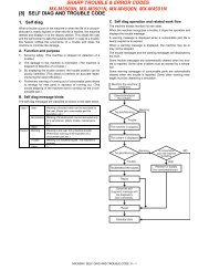
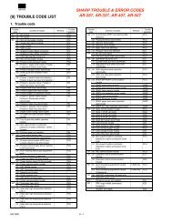
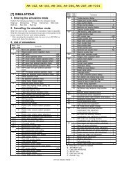
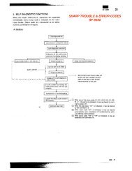
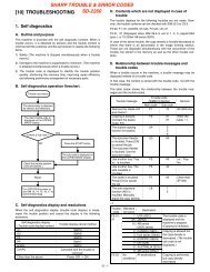
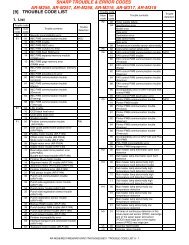
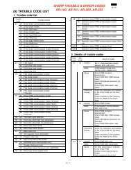

![[10] TEST COMMAND, TROUBLE CODES - OlsonBros](https://img.yumpu.com/18824764/1/190x245/10-test-command-trouble-codes-olsonbros.jpg?quality=85)