Table of Contents D-Link DSL-2730U User Manual 1
Table of Contents D-Link DSL-2730U User Manual 1
Table of Contents D-Link DSL-2730U User Manual 1

You also want an ePaper? Increase the reach of your titles
YUMPU automatically turns print PDFs into web optimized ePapers that Google loves.
<strong>Table</strong> <strong>of</strong> <strong>Contents</strong><br />
D-<strong>Link</strong> <strong>DSL</strong>-<strong>2730U</strong> <strong>User</strong> <strong>Manual</strong> 1
<strong>Table</strong> <strong>of</strong> <strong>Contents</strong><br />
PACKAGE CONTENTS .......................................................................................... 4<br />
SYSTEM REQUIREMENTS..................................................................................... 4<br />
FEATURES .......................................................................................................... 5<br />
HARDWARE OVERVIEW .................................................................................... 7<br />
Connections ................................................................................................. 7<br />
LEDs............................................................................................................. 8<br />
INSTALLATION .................................................................................................... 9<br />
BEFORE YOU BEGIN............................................................................................ 9<br />
INSTALLATION NOTES ........................................................................................ 10<br />
INFORMATION YOU WILL NEED FROM YOUR A<strong>DSL</strong> SERVICE PROVIDER................. 12<br />
INFORMATION YOU WILL NEED ABOUT <strong>DSL</strong>-<strong>2730U</strong> ............................................ 14<br />
DEVICE INSTALLATION ....................................................................................... 16<br />
Power on Router ........................................................................................ 16<br />
Factory Reset Button.................................................................................. 17<br />
Network Connections ................................................................................. 17<br />
CONFIGURATION.............................................................................................. 18<br />
WEB-BASED CONFIGURATION UTILITY ................................................................ 18<br />
DEVICE INFO ..................................................................................................... 19<br />
SUMMARY......................................................................................................... 20<br />
WAN................................................................................................................ 21<br />
STATISTICS ....................................................................................................... 22<br />
ROUTE ............................................................................................................. 25<br />
ARP ................................................................................................................ 25<br />
DHCP.............................................................................................................. 25<br />
ADVANCED SETUP........................................................................................... 26<br />
LAYER2 INTERFACE........................................................................................... 26<br />
ATM Interface ............................................................................................. 27<br />
WAN SERVICE.................................................................................................. 28<br />
LAN................................................................................................................. 46<br />
NAT................................................................................................................. 48<br />
Virtual Servers............................................................................................ 48<br />
Port Triggering ............................................................................................ 49<br />
DMZ Host ................................................................................................... 50<br />
SECURITY......................................................................................................... 51<br />
IP Filtering .................................................................................................. 51<br />
<strong>Table</strong> <strong>of</strong> <strong>Contents</strong><br />
PARENTAL CONTROL.......................................................................................... 55<br />
URL Filter.................................................................................................... 56<br />
QUALITY OF SERVICE......................................................................................... 57<br />
Queue Config.............................................................................................. 58<br />
QoS Classification ...................................................................................... 59<br />
ROUTING .......................................................................................................... 60<br />
Default Gateway ......................................................................................... 60<br />
Static Route ................................................................................................ 60<br />
Policy Routing............................................................................................. 61<br />
RIP.............................................................................................................. 62<br />
DNS................................................................................................................. 63<br />
DNS Server................................................................................................. 63<br />
Dynamic DNS ............................................................................................. 63<br />
<strong>DSL</strong> ................................................................................................................. 65<br />
UPNP .............................................................................................................. 68<br />
DNS PROXY ..................................................................................................... 68<br />
INTERFACE GROUP............................................................................................ 69<br />
IPSEC .............................................................................................................. 70<br />
MULTICAST ....................................................................................................... 72<br />
WIRELESS.......................................................................................................... 73<br />
BASIC ............................................................................................................... 73<br />
SECURITY ......................................................................................................... 74<br />
MAC FILTER ..................................................................................................... 75<br />
WIRELESS BRIDGE ............................................................................................ 76<br />
ADVANCED........................................................................................................ 77<br />
STATION INFO.................................................................................................... 78<br />
DIAGNOSTICS ................................................................................................... 79<br />
MANAGEMENT .................................................................................................. 79<br />
SETTINGS ......................................................................................................... 80<br />
SYSTEM LOG..................................................................................................... 80<br />
SNMP AGENT................................................................................................... 82<br />
TR-069 CLIENT................................................................................................. 83<br />
INTERNET TIME.................................................................................................. 84<br />
ACCESS CONTROL ............................................................................................ 85<br />
Passwords .................................................................................................. 85<br />
UPDATE SOFTWARE........................................................................................... 86<br />
REBOOT............................................................................................................ 86<br />
D-<strong>Link</strong> <strong>DSL</strong>-<strong>2730U</strong> <strong>User</strong> <strong>Manual</strong> 2
<strong>Table</strong> <strong>of</strong> <strong>Contents</strong><br />
TROUBLESHOOTING ....................................................................................... 87<br />
NETWORKING BASICS .................................................................................... 89<br />
CHECK YOUR IP ADDRESS ................................................................................ 89<br />
STATICALLY ASSIGN AN IP ADDRESS................................................................... 90<br />
TECHNICAL SPECIFICATIONS ........................................................................ 91<br />
D-<strong>Link</strong> <strong>DSL</strong>-<strong>2730U</strong> <strong>User</strong> <strong>Manual</strong> 3
Section 1 - Product Overview<br />
• <strong>DSL</strong>-<strong>2730U</strong> Wireless A<strong>DSL</strong> Router<br />
• Power Adapter<br />
• CD-ROM with <strong>User</strong> <strong>Manual</strong><br />
• One Micro Splitter<br />
• One twisted-pair telephone cable used for A<strong>DSL</strong> connection<br />
• One straight-through Ethernet cable<br />
• One Quick Installation Guide<br />
Note: Using a power supply with a different voltage rating than the one included<br />
with the <strong>DSL</strong>-<strong>2730U</strong> will cause damage and void the warranty for this product.<br />
Package <strong>Contents</strong><br />
System Requirements<br />
• A<strong>DSL</strong> Internet service<br />
• Computer with:<br />
• 200MHz Processor<br />
• 64MB Memory<br />
• CD-ROM Drive<br />
• Ethernet Adapter with TCP/IP Protocol Installed<br />
• Internet Explorer v6 or later, FireFox v1.5<br />
• Computer with Windows 2000, Windows XP, or Windows Vista<br />
D-<strong>Link</strong> <strong>DSL</strong>-<strong>2730U</strong> <strong>User</strong> <strong>Manual</strong> 4
Section 1 - Product Overview<br />
11<br />
Features<br />
• PPP (Point-to-Point Protocol) Security – The <strong>DSL</strong>-<strong>2730U</strong> A<strong>DSL</strong> Router supports PAP (Password Authentication Protocol) and CHAP<br />
(Challenge Handshake Authentication Protocol) for PPP connections. The Router also supports MSCHAP.<br />
• DHCP Support – Dynamic Host Configuration Protocol automatically and dynamically assigns all LAN IP settings to each host on your<br />
network. This eliminates the need to reconfigure every host whenever changes in network topology occur.<br />
• Network Address Translation (NAT) – For small <strong>of</strong>fice environments, the <strong>DSL</strong>-<strong>2730U</strong> allows multiple users on the LAN to access the<br />
Internet concurrently through a single Internet account. This provides Internet access to everyone in the <strong>of</strong>fice for the price <strong>of</strong> a single user.<br />
NAT improves network security in effect by hiding the private network behind one global and visible IP address. NAT address mapping can<br />
also be used to link two IP domains via a LAN-to-LAN connection.<br />
• TCP/IP (Transfer Control Protocol/Internet Protocol) – The <strong>DSL</strong>-<strong>2730U</strong> supports TCP/IP protocol, the language used for the Internet. It is<br />
compatible with access servers manufactured by major vendors.<br />
• RIP-1/RIP-2 – The <strong>DSL</strong>-<strong>2730U</strong> supports both RIP-1 and RIP-2 exchanges with other routers. Using both versions lets the Router to<br />
communicate with all RIP enabled devices.<br />
• Static Routing – This allows you to select a data path to a particular network destination that will remain in the routing table and never “age<br />
out”. If you wish to define a specific route that will always be used for data traffic from your LAN to a specific destination within your LAN (for<br />
example to another router or a server) or outside your network (to an ISP defined default gateway for instance).<br />
• Default Routing – This allows you to choose a default path for incoming data packets for which the destination address is unknown. This is<br />
particularly useful when/if the Router functions as the sole connection to the Internet.<br />
• ATM (Asynchronous Transfer Mode) – The <strong>DSL</strong>-<strong>2730U</strong> supports Bridged Ethernet over ATM (RFC1483), IP over ATM (RFC1577), and<br />
PPP over ATM (RFC 2364).<br />
• Precise ATM Traffic Shaping – Traffic shaping is a method <strong>of</strong> controlling the flow rate <strong>of</strong> ATM data cells. This function helps to establish the<br />
Quality <strong>of</strong> Service for ATM data transfer.<br />
D-<strong>Link</strong> <strong>DSL</strong>-<strong>2730U</strong> <strong>User</strong> <strong>Manual</strong> 5
Section 1 - Product Overview<br />
• G.hs (Auto-handshake) – This allows the Router to automatically choose either the G.lite or G.dmt A<strong>DSL</strong> connection standards.<br />
• High Performance – Very high rates <strong>of</strong> data transfer are possible with the Router. Up to 8 Mbps downstream bit rate using the G.dmt<br />
standard.<br />
• Full Network Management – The <strong>DSL</strong>-<strong>2730U</strong> incorporates SNMP (Simple Network Management Protocol) support for web-based<br />
management and text-based network management via an RS-232 or Telnet connection.<br />
• Telnet Connection – The Telnet enables a network manager to access the Router’s management s<strong>of</strong>tware remotely.<br />
• Easy Installation – The <strong>DSL</strong>-<strong>2730U</strong> uses a web-based graphical user interface program for convenient management access and easy set<br />
up. Any common web browser s<strong>of</strong>tware can be used to manage the Router.<br />
D-<strong>Link</strong> <strong>DSL</strong>-<strong>2730U</strong> <strong>User</strong> <strong>Manual</strong> 6
Section 1 - Product Overview<br />
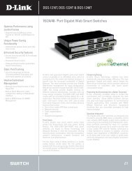
Antenna<br />
Reset Button<br />
On the bottom <strong>of</strong> the<br />
device,push it to reset<br />
to factory confugration<br />
Hardware Overview<br />
Connections<br />
A<strong>DSL</strong> Port<br />
Use the A<strong>DSL</strong> cable to connect<br />
to the your telephone line (RJ-11<br />
port)<br />
Wireless ON/OFF<br />
Button<br />
Push the button to on/<strong>of</strong>f<br />
wireless function<br />
Ethernet Port<br />
Use the Ethernet port to connect<br />
the Router to a computer or an<br />
Ethernet LAN<br />
WPS Button<br />
Push the button to on/<strong>of</strong>f<br />
WPS function<br />
Power Button<br />
Push in to power-on the Router.<br />
Push again to power-<strong>of</strong>f the<br />
Router.<br />
Power Insert<br />
Use the adapter shipped with the<br />
Router to connect to power<br />
source.<br />
D-<strong>Link</strong> <strong>DSL</strong>-<strong>2730U</strong> <strong>User</strong> <strong>Manual</strong> 7
Section 1 - Product Overview<br />
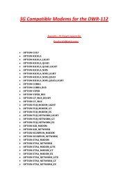
LAN<br />
A solid green light indicates a valid link on<br />
startup. This light will blink when there is<br />
activity currently passing through the<br />
Ethernet port.<br />
Power<br />
A steady green light indicates the unit is<br />
powered on. When the device is powered<br />
<strong>of</strong>f it remains dark. Lights steady green<br />
during power on self-test (POST) means<br />
the power connection works properly.<br />
WLAN<br />
A steady green light indicates a<br />
wireless connection. A blinking<br />
green light indicates activity on<br />
the WLAN interface.<br />
Hardware Overview<br />
LEDs<br />
WPS<br />
A blinking green light indicates the<br />
device has connected the wireless<br />
network card, A blinking green<br />
light indicates activity on WPS.<br />
<strong>DSL</strong><br />
A steady green light indicates a<br />
valid A<strong>DSL</strong> connection. This will<br />
light after the A<strong>DSL</strong> negotiation<br />
process has been settled. A<br />
blinking green light indicates that<br />
ADLS is attempting to sync.<br />
Internet<br />
A steady green light indicates a valid<br />
internet connection.<br />
D-<strong>Link</strong> <strong>DSL</strong>-<strong>2730U</strong> <strong>User</strong> <strong>Manual</strong> 8
Section 2 – Installation<br />
Installation<br />
This section will walk you through the installation process. Placement <strong>of</strong> the Router is very important. Do not place the Router in an enclosed area<br />
such as a closet, cabinet, or in the attic or garage.<br />
Before You Begin<br />
Please read and make sure you understand all the prerequisites for proper installation <strong>of</strong> your new Router. Have all the necessary information and<br />
equipment on hand before beginning the installation.<br />
D-<strong>Link</strong> <strong>DSL</strong>-<strong>2730U</strong> <strong>User</strong> <strong>Manual</strong> 9
Section 2 – Installation<br />
Installation Notes<br />
In order to establish a connection to the Internet it will be necessary to provide information to the Router that will be stored in its memory. For some<br />
users, only their account information (<strong>User</strong>name and Password) is required. For others, various parameters that control and define the Internet<br />
connection will be required. You can print out the two pages below and use the tables to list this information. This way you have a hard copy <strong>of</strong> all<br />
the information needed to setup the Router. If it is necessary to reconfigure the device, all the necessary information can be easily accessed. Be<br />
sure to keep this information safe and private.<br />
Low Pass Filters<br />
Since A<strong>DSL</strong> and telephone services share the same copper wiring to carry their respective signals, a filtering mechanism may be necessary to<br />
avoid mutual interference. A low pass filter device can be installed for each telephone that shares the line with the A<strong>DSL</strong> line. These filters are easy<br />
to install passive devices that connect to the A<strong>DSL</strong> device and/or telephone using standard telephone cable. Ask your service provider for more<br />
information about the use <strong>of</strong> low pass filters with your installation.<br />
Operating Systems<br />
The <strong>DSL</strong>-<strong>2730U</strong> uses an HTML-based web interface for setup and management. The web configuration manager may be accessed using any<br />
operating system capable <strong>of</strong> running web browser s<strong>of</strong>tware, including Windows 98 SE, Windows ME, Windows 2000, Windows XP, and Windows<br />
Vista.<br />
Web Browser<br />
Any common web browser can be used to configure the Router using the web configuration management s<strong>of</strong>tware. The program is designed to<br />
work best with more recently released browsers such as Opera, Micros<strong>of</strong>t Internet Explorer® version 6.0, Netscape Navigator® version 6.2.3, or<br />
later versions. The web browser must have JavaScript enabled. JavaScript is enabled by default on many browsers. Make sure JavaScript has not<br />
been disabled by other s<strong>of</strong>tware (such as virus protection or web user security packages) that may be running on your computer.<br />
Ethernet Port (NIC Adapter)<br />
Any computer that uses the Router must be able to connect to it through the Ethernet port on the Router. This connection is an Ethernet connection<br />
and therefore requires that your computer be equipped with an Ethernet port as well. Most notebook computers are now sold with an Ethernet port<br />
already installed. Likewise, most fully assembled desktop computers come with an Ethernet NIC adapter as standard equipment. If your computer<br />
does not have an Ethernet port, you must install an Ethernet NIC adapter before you can use the Router. If you must install an adapter, follow the<br />
installation instructions that come with the Ethernet NIC adapter.<br />
D-<strong>Link</strong> <strong>DSL</strong>-<strong>2730U</strong> <strong>User</strong> <strong>Manual</strong> 10
Section 2 – Installation<br />
Additional S<strong>of</strong>tware<br />
It may be necessary to install s<strong>of</strong>tware on your computer that enables the computer to access the Internet. Additional s<strong>of</strong>tware must be installed if<br />
you are using the device a simple bridge. For a bridged connection, the information needed to make and maintain the Internet connection is stored<br />
on another computer or gateway device, not in the Router itself.<br />
If your A<strong>DSL</strong> service is delivered through a PPPoE or PPPoA connection, the information needed to establish and maintain the Internet connection<br />
can be stored in the Router. In this case, it is not necessary to install s<strong>of</strong>tware on your computer. It may however be necessary to change some<br />
settings in the device, including account information used to identify and verify the connection.<br />
All connections to the Internet require a unique global IP address. For bridged connections, the global IP settings must reside in a TCP/IP enabled<br />
device on the LAN side <strong>of</strong> the bridge, such as a PC, a server, a gateway device such as a router or similar firewall hardware. The IP address can be<br />
assigned in a number <strong>of</strong> ways. Your network service provider will give you instructions about any additional connection s<strong>of</strong>tware or NIC<br />
configuration that may be required.<br />
D-<strong>Link</strong> <strong>DSL</strong>-<strong>2730U</strong> <strong>User</strong> <strong>Manual</strong> 11
Section 2 – Installation<br />
Information you will need from your A<strong>DSL</strong> service<br />
provider<br />
<strong>User</strong>name<br />
This is the <strong>User</strong>name used to log on to your A<strong>DSL</strong> service provider’s network. Your A<strong>DSL</strong> service provider uses this to identify your account.<br />
Password<br />
This is the Password used, in conjunction with the <strong>User</strong>name above, to log on to your A<strong>DSL</strong> service provider’s network. This is used to verify the<br />
identity <strong>of</strong> your account.<br />
WAN Setting / Connection Type<br />
These settings describe the method your A<strong>DSL</strong> service provider uses to transport data between the Internet and your computer. Most users will use<br />
the default settings. You may need to specify one <strong>of</strong> the following WAN Setting and Connection Type configurations (Connection Type settings listed<br />
in parenthesis):<br />
• PPPoE/PPoA (PPPoE LLC, PPPoA LLC or PPPoA VC-Mux)<br />
• Bridge Mode (1483 Bridged IP LLC or 1483 Bridged IP VC Mux)<br />
• IPoA/MER (Static IP Address) (Bridged IP LLC, 1483 Bridged IP VC Mux, 1483 Routed IP LLC, 1483 Routed IP VC-Mux or IPoA)<br />
• MER (Dynamic IP Address) (1483 Bridged IP LLC or 1483 Bridged IP VC-Mux)<br />
Modulation Type<br />
A<strong>DSL</strong> uses various standardized modulation techniques to transmit data over the allotted signal frequencies. Some users may need to change the<br />
type <strong>of</strong> modulation used for their service. The default <strong>DSL</strong> modulation (A<strong>DSL</strong>2+ Multi-Mode) used for the Router automatically detects all types <strong>of</strong><br />
A<strong>DSL</strong>, A<strong>DSL</strong>2, and A<strong>DSL</strong>2+ modulation.<br />
Security Protocol<br />
This is the method your A<strong>DSL</strong> service provider will use to verify your <strong>User</strong>name and Password when you log on to their network. Your Router<br />
supports the PAP and CHAP protocols.<br />
D-<strong>Link</strong> <strong>DSL</strong>-<strong>2730U</strong> <strong>User</strong> <strong>Manual</strong> 12
Section 2 – Installation<br />
VPI<br />
Most users will not be required to change this setting. The Virtual Path Identifier (VPI) is used in conjunction with the Virtual Channel Identifier (VCI)<br />
to identify the data path between your A<strong>DSL</strong> service provider’s network and your computer. If you are setting up the Router for multiple virtual<br />
connections, you will need to configure the VPI and VCI as instructed by your A<strong>DSL</strong> service provider for the additional connections. This setting can<br />
be changed in the WAN Settings window <strong>of</strong> the web management interface.<br />
VCI<br />
Most users will not be required to change this setting. The Virtual Channel Identifier (VCI) used in conjunction with the VPI to identify the data path<br />
between your A<strong>DSL</strong> service provider’s network and your computer. If you are setting up the Router for multiple virtual connections, you will need to<br />
configure the VPI and VCI as instructed by your A<strong>DSL</strong> service provider for the additional connections. This setting can be changed in the WAN<br />
Settings window <strong>of</strong> the web management interface.<br />
D-<strong>Link</strong> <strong>DSL</strong>-<strong>2730U</strong> <strong>User</strong> <strong>Manual</strong> 13
Section 2 – Installation<br />
Information you will need about <strong>DSL</strong>-<strong>2730U</strong><br />
<strong>User</strong>name<br />
This is the <strong>User</strong>name needed to access the Router’s management interface. When you attempt to connect to the device through a web browser you<br />
will be prompted to enter this <strong>User</strong>name. The default <strong>User</strong>name for the Router is “admin.” The user cannot change this.<br />
Password<br />
This is the Password you will be prompted to enter when you access the Router’s management interface. The default Password is “admin.” The<br />
user may change this.<br />
LAN IP addresses for the <strong>DSL</strong>-<strong>2730U</strong><br />
This is the IP address you will enter into the Address field <strong>of</strong> your web browser to access the Router’s configuration graphical user interface (GUI)<br />
using a web browser. The default IP address is 192.168.1.1. This may be changed to suit any IP address scheme the user desires. This address will<br />
be the base IP address used for DHCP service on the LAN when DHCP is enabled.<br />
LAN Subnet Mask for the <strong>DSL</strong>-<strong>2730U</strong><br />
This is the subnet mask used by the <strong>DSL</strong>-<strong>2730U</strong>, and will be used throughout your LAN. The default subnet mask is 255.255.255.0. This can be<br />
changed later.<br />
D-<strong>Link</strong> <strong>DSL</strong>-<strong>2730U</strong> <strong>User</strong> <strong>Manual</strong> 14
Section 2 – Installation<br />
Information you will need about your LAN or computer:<br />
Ethernet NIC<br />
If your computer has an Ethernet NIC, you can connect the <strong>DSL</strong>-<strong>2730U</strong> to this Ethernet port using an Ethernet cable. You can also use the Ethernet<br />
ports on the <strong>DSL</strong>-<strong>2730U</strong> to connect to other computer or Ethernet devices.<br />
DHCP Client status<br />
Your <strong>DSL</strong>-<strong>2730U</strong> A<strong>DSL</strong> Router is configured, by default, to be a DHCP server. This means that it can assign an IP address, subnet mask, and a<br />
default gateway address to computers on your LAN. The default range <strong>of</strong> IP addresses the <strong>DSL</strong>-<strong>2730U</strong> will assign are from 192.168.1.2 to<br />
192.168.1.254. Your computer (or computers) needs to be configured to obtain an IP address automatically (that is, they need to be configured as<br />
DHCP clients.)<br />
It is recommended that your collect and record this information here, or in some other secure place, in case you have to re-configure your A<strong>DSL</strong><br />
connection in the future.<br />
Once you have the above information, you are ready to setup and configure your <strong>DSL</strong>-<strong>2730U</strong> A<strong>DSL</strong> Router.<br />
D-<strong>Link</strong> <strong>DSL</strong>-<strong>2730U</strong> <strong>User</strong> <strong>Manual</strong> 15
Section 2 – Installation<br />
Device Installation<br />
The <strong>DSL</strong>-<strong>2730U</strong> connects two separate physical interfaces, an A<strong>DSL</strong> (WAN) and an Ethernet (LAN) interface. Place the Router in a location where<br />
it can be connected to the various devices as well as to a power source. The Router should not be located where it will be exposed to moisture or<br />
excessive heat. Make sure the cables and power cord are placed safely out <strong>of</strong> the way so they do not create a tripping hazard. As with any electrical<br />
appliance, observe common sense safety procedures.<br />
The Router can be placed on a shelf or desktop, ideally you should be able to see the LED indicators on the front if you need to view them for<br />
troubleshooting.<br />
Power on Router<br />
The Router must be used with the power adapter included with the device.<br />
1. Insert the DC Power Adapter cord into the power receptacle located on the rear panel <strong>of</strong> the Router and plug the adapter into a suitable nearby<br />
power source.<br />
2. Depress the Power button into the on position. You should see the Power LED indicator light up and remain lit. The Status LED should light solid<br />
green and begin to blink after a few seconds.<br />
3. If the Ethernet port is connected to a working device, check the LAN LED indicators to make sure the connection is valid. The Router will attempt<br />
to establish the A<strong>DSL</strong> connection, if the A<strong>DSL</strong> line is connected and the Router is properly configured this should light up after several seconds.<br />
If this is the first time installing the device, some settings may need to be changed before the Router can establish a connection.<br />
D-<strong>Link</strong> <strong>DSL</strong>-<strong>2730U</strong> <strong>User</strong> <strong>Manual</strong> 16
Section 2 – Installation<br />
Factory Reset Button<br />
The Router may be reset to the original factory default settings by using a ballpoint or paperclip to gently push down the reset button in the following<br />
sequence:<br />
1. Press and hold the reset button while the device is powered <strong>of</strong>f.<br />
2. Turn on the power.<br />
3. Wait for 10 seconds and then release the reset button.<br />
Remember that this will wipe out any settings stored in flash memory including user account information and LAN IP settings. The device settings<br />
will be restored to the factory default IP address 192.168.1.1 and the subnet mask is 255.255.255.0, the default management <strong>User</strong>name is “admin”<br />
and the default Password is “admin.”<br />
Network Connections<br />
Connect A<strong>DSL</strong> Line<br />
Use the A<strong>DSL</strong> cable included with the Router to connect it to a telephone wall socket or receptacle. Plug one end <strong>of</strong> the cable into the A<strong>DSL</strong> port<br />
(RJ-11 receptacle) on the rear panel <strong>of</strong> the Router and insert the other end into the RJ-11 wall socket. If you are using a low pass filter device, follow<br />
the instructions included with the device or given to you by your service provider. The A<strong>DSL</strong> connection represents the WAN interface, the<br />
connection to the Internet. It is the physical link to the service provider’s network backbone and ultimately to the Internet.<br />
Connect Router to Ethernet<br />
The Router may be connected to a single computer or Ethernet device through the 10BASE-TX Ethernet port on the rear panel. Any connection to<br />
an Ethernet concentrating device such as a switch or hub must operate at a speed <strong>of</strong> 10/100 Mbps only. When connecting the Router to any<br />
Ethernet device that is capable <strong>of</strong> operating at speeds higher than 10Mbps, be sure that the device has auto-negotiation (NWay) enabled for the<br />
connecting port. Use standard twisted-pair cable with RJ-45 connectors. The RJ-45 port on the Router is a crossed port (MDI-X). Follow standard<br />
Ethernet guidelines when deciding what type <strong>of</strong> cable to use to make this connection. When connecting the Router directly to a PC or server use a<br />
normal straight-through cable. You should use a crossed cable when connecting the Router to a normal (MDI-X) port on a switch or hub. Use a<br />
normal straight-through cable when connecting it to an uplink (MDI-II) port on a hub or switch. The rules governing Ethernet cable lengths apply to<br />
the LAN to Router connection. Be sure that the cable connecting the LAN to the Router does not exceed 100 meters.<br />
Hub or Switch to Router Connection<br />
Connect the Router to an uplink port (MDI-II) on an Ethernet hub or switch with a straight-through cable. If you wish to reserve the uplink port on the<br />
switch or hub for another device, connect to any on the other MDI-X ports (1x, 2x, etc.) with a crossed cable.<br />
Computer to Router Connection<br />
You can connect the Router directly to a 10/100BASE-TX Ethernet adapter card (NIC) installed on a PC using the Ethernet cable provided.<br />
D-<strong>Link</strong> <strong>DSL</strong>-<strong>2730U</strong> <strong>User</strong> <strong>Manual</strong> 17
Appendix A – Troubleshooting<br />
Configuration<br />
This section will show you how to configure your new D-<strong>Link</strong> Router using the web-based configuration utility.<br />
Web-based Configuration Utility<br />
Connect to the Router<br />
The default IP address for A<strong>DSL</strong> MODEM is: 192.168.1.1; The Subnet Mask is:255.255.255.0. <strong>User</strong>s can configure A<strong>DSL</strong> MODEM through an<br />
Internet browser. A<strong>DSL</strong> MODEM can be used as gateway and DNS server; users need to set the computer’s TCP/IP protocol as follow:<br />
1. Set the computer IP address at same segment <strong>of</strong> A<strong>DSL</strong> MODEM, such as set the IP address <strong>of</strong> the network card to one <strong>of</strong> the “192.168.1.2”<br />
~ “192.168.1.254”.<br />
2. Set the computer’s gateway the same IP address as the A<strong>DSL</strong> Modem’s.<br />
3. Set computer’s DNS server the same as A<strong>DSL</strong> Modem’s IP address or that <strong>of</strong> an effective DNS server.<br />
To access the configuration utility, open a web-browser such as Internet<br />
Explorer and enter the IP address <strong>of</strong> the router (192.168.1.1).<br />
Type “admin” for the <strong>User</strong> Name and “admin” in the Password field. If<br />
you get a Page Cannot be Displayed error, please refer to the<br />
Troubleshooting section for assistance.<br />
D-<strong>Link</strong> <strong>DSL</strong>-<strong>2730U</strong> <strong>User</strong> <strong>Manual</strong> 18
Appendix A – Troubleshooting<br />
Device Info<br />
To access the Device Info window, click either the Device Info or Summary button in the Device Info directory. The following page opens:<br />
D-<strong>Link</strong> <strong>DSL</strong>-<strong>2730U</strong> <strong>User</strong> <strong>Manual</strong> 19
Appendix A – Troubleshooting<br />
Summary<br />
To access the Router’s first Summary window, click the Summary button in the Device Info directory.<br />
This window displays the current status <strong>of</strong> your <strong>DSL</strong> connection, including<br />
the s<strong>of</strong>tware version, LAN IP address, and DNS server address.<br />
D-<strong>Link</strong> <strong>DSL</strong>-<strong>2730U</strong> <strong>User</strong> <strong>Manual</strong> 20
Appendix A – Troubleshooting<br />
WAN<br />
To access the WAN Info window, click the WAN button in the Device Info directory.<br />
This window displays the current status <strong>of</strong> your WAN connection.<br />
D-<strong>Link</strong> <strong>DSL</strong>-<strong>2730U</strong> <strong>User</strong> <strong>Manual</strong> 21
Appendix A – Troubleshooting<br />
Statistics<br />
To access the Router’s first Statistics window, click the Statistics button in the Device Info directory.<br />
This window displays the Router’s LAN statistics. Click the Reset<br />
Statistics button to refresh these statistics.<br />
This window displays the Router’s WAN statistics. Click the Reset<br />
Statistics button to refresh these statistics.<br />
D-<strong>Link</strong> <strong>DSL</strong>-<strong>2730U</strong> <strong>User</strong> <strong>Manual</strong> 22
Appendix A – Troubleshooting<br />
This window displays the Router’s XTM statistics. Click the Reset button<br />
to refresh these statistics.<br />
D-<strong>Link</strong> <strong>DSL</strong>-<strong>2730U</strong> <strong>User</strong> <strong>Manual</strong> 23
Appendix A – Troubleshooting<br />
This window displays the Router’s x<strong>DSL</strong> statistics. Click the Reset<br />
Statistics button to refresh these statistics.<br />
Click the x<strong>DSL</strong> BER Test button to access the A<strong>DSL</strong> Bit Error Rate Test<br />
window displayed below:<br />
D-<strong>Link</strong> <strong>DSL</strong>-<strong>2730U</strong> <strong>User</strong> <strong>Manual</strong> 24
Appendix A – Troubleshooting<br />
Route<br />
To access the Device Info – Route window, click the Route button in the Device Info directory.<br />
This read-only window displays routing info.<br />
ARP<br />
To access the Device Info – ARP window, click the ARP button in the Device Info directory.<br />
This read-only window displays Address Resolution Protocol info.<br />
DHCP<br />
To access the Device Info – DHCP Leases window, click the DHCP button in the Device Info directory.<br />
This read-only window displays DHCP lease info.<br />
D-<strong>Link</strong> <strong>DSL</strong>-<strong>2730U</strong> <strong>User</strong> <strong>Manual</strong> 25
Appendix A – Troubleshooting<br />
Advanced Setup<br />
This chapter include the more advanced features used for network management and security as well as administrative tools to manage the Router,<br />
view status and other information used to examine performance and for troubleshooting.<br />
Layer2 Interface<br />
To access the <strong>DSL</strong> ATM Interface Configuration window, click the ATM Interface button in the Layer2 Interface directory.<br />
This window is used to configure the ATM interface. You can add and<br />
delete ATM interface on this window.<br />
If you are setting up the ATM interface for the first time, click the Add<br />
button.<br />
D-<strong>Link</strong> <strong>DSL</strong>-<strong>2730U</strong> <strong>User</strong> <strong>Manual</strong> 26
Appendix A – Troubleshooting<br />
ATM Interface<br />
The ATM PVC Configuration window allows you to set up ATM PVC<br />
configuration. Enter Virtual Path Identifier,and Virtual Channel Identifier.<br />
The VPI and VCI values should be provided by your ISP. This window<br />
also allows you to select <strong>DSL</strong> <strong>Link</strong> Type, PPPoA、IpoA and EoA (EoA is<br />
for PPPoE, IPoE, and Bridge)<br />
Use the drop-down menu to select the desired Encapsulation Mode..<br />
Click the Apply / Save button to Save.<br />
D-<strong>Link</strong> <strong>DSL</strong>-<strong>2730U</strong> <strong>User</strong> <strong>Manual</strong> 27
Appendix A – Troubleshooting<br />
WAN Service<br />
To access the Wide Area Network (WAN) Service Setup window, click the WAN Service button in the Advanced Setup directory.<br />
This window is used to configure the WAN interface. You can add and<br />
delete WAN interface on this window.<br />
If you are setting up the WAN interface for the first time, click the Add<br />
button.<br />
D-<strong>Link</strong> <strong>DSL</strong>-<strong>2730U</strong> <strong>User</strong> <strong>Manual</strong> 28
Appendix A – Troubleshooting<br />
The WAN Service Interface Configuration Configuration window allows<br />
select a layer 2 interface for this service. Click the Next button to continue.<br />
D-<strong>Link</strong> <strong>DSL</strong>-<strong>2730U</strong> <strong>User</strong> <strong>Manual</strong> 29
Appendix A – Troubleshooting<br />
This window allows you to select the appropriate connection type. The<br />
choices include PPP over ATM (PPPoA), PPP over Ethernet (PPPoE), IP<br />
over Ethernet (IpoE), IP over ATM (IPoA), and Bridging.<br />
WAN Service Configuration – PPPoE<br />
Click the PPP over Ethernet (PPPoE) radio button on this window. This<br />
window also allows you to use the drop-down menu to enable IPv6<br />
service. Click the Next button to continue.<br />
D-<strong>Link</strong> <strong>DSL</strong>-<strong>2730U</strong> <strong>User</strong> <strong>Manual</strong> 30
Appendix A – Troubleshooting<br />
WAN Service Configuration – PPPoE<br />
This window allows you to set the username and the password for your<br />
PPP connection. This information is obtained from your ISP. Additional<br />
settings on this window will also depend on your ISP. And You can input<br />
2 nd ip on this page. Click the Next button to continue.<br />
D-<strong>Link</strong> <strong>DSL</strong>-<strong>2730U</strong> <strong>User</strong> <strong>Manual</strong> 31
Appendix A – Troubleshooting<br />
WAN Service Configuration – PPPoE<br />
Default gateway interface list can have multiple WAN interfaces served as<br />
system default gateways but only one will be used according to the priority<br />
with the first being the higest and the last one the lowest priority if the<br />
WAN interface is connected. Priority order can be changed by removing<br />
all and adding them back in again. Click the Next button to continue.<br />
WAN Service Configuration – PPPoE<br />
Select DNS Server Interface from available WAN interfaces OR enter<br />
static DNS server IP addresses for the system. In ATM mode, if only a<br />
single PVC with IPoA or static IPoE protocol is configured, Static DNS<br />
server IP addresses must be entered.<br />
DNS Server Interfaces can have multiple WAN interfaces served as<br />
system dns servers but only one will be used according to the priority with<br />
the first being the higest and the last one the lowest priority if the WAN<br />
interface is connected. Priority order can be changed by removing all and<br />
adding them back in again. Click the Next button to continue<br />
D-<strong>Link</strong> <strong>DSL</strong>-<strong>2730U</strong> <strong>User</strong> <strong>Manual</strong> 32
Appendix A – Troubleshooting<br />
WAN Service Configuration – PPPoE<br />
This summary window allows you to confirm the settings you have just<br />
made. Click the Apply / Save button to save your new PPP over Ethernet<br />
settings and restart the Router.<br />
D-<strong>Link</strong> <strong>DSL</strong>-<strong>2730U</strong> <strong>User</strong> <strong>Manual</strong> 33
Appendix A – Troubleshooting<br />
WAN Service Configuration – IPoE<br />
Click the IP over Ethernet radio button on this window. Click the Next<br />
button to continue.<br />
D-<strong>Link</strong> <strong>DSL</strong>-<strong>2730U</strong> <strong>User</strong> <strong>Manual</strong> 34
Appendix A – Troubleshooting<br />
WAN Service Configuration – IPoE<br />
This window allows you to configure the WAN IP settings. This information<br />
is obtained from your ISP. Click the Next button to continue.<br />
D-<strong>Link</strong> <strong>DSL</strong>-<strong>2730U</strong> <strong>User</strong> <strong>Manual</strong> 35
Appendix A – Troubleshooting<br />
WAN Service Configuration – IPoE<br />
This window allows you to enable or disable Network Address Translation<br />
and a firewall for your Router. In addition, you can enable or disable IGMP<br />
multicasting. And You can input 2 nd ip on this page. Click the Next button<br />
to continue.<br />
WAN Service Configuration – IPoE<br />
Default gateway interface list can have multiple WAN interfaces served as<br />
system default gateways but only one will be used according to the priority<br />
with the first being the higest and the last one the lowest priority if the<br />
WAN interface is connected. Priority order can be changed by removing<br />
all and adding them back in again. Click the Next button to continue<br />
D-<strong>Link</strong> <strong>DSL</strong>-<strong>2730U</strong> <strong>User</strong> <strong>Manual</strong> 36
Appendix A – Troubleshooting<br />
WAN Service Configuration – IPoE<br />
Select DNS Server Interface from available WAN interfaces OR enter<br />
static DNS server IP addresses for the system. In ATM mode, if only a<br />
single PVC with IPoA or static IPoE protocol is configured, Static DNS<br />
server IP addresses must be entered.<br />
DNS Server Interfaces can have multiple WAN interfaces served as<br />
system dns servers but only one will be used according to the priority with<br />
the first being the higest and the last one the lowest priority if the WAN<br />
interface is connected. Priority order can be changed by removing all and<br />
adding them back in again. Click the Next button to continue<br />
WAN Service Configuration – IPoE<br />
This summary window allows you to confirm the settings you have just<br />
made. Click the Apply / Save button to save your new IP over Ethernet<br />
settings and restart the Router.<br />
D-<strong>Link</strong> <strong>DSL</strong>-<strong>2730U</strong> <strong>User</strong> <strong>Manual</strong> 37
Appendix A – Troubleshooting<br />
WAN Service Configuration – BRIDGING<br />
Click the Bridge radio button on this window. Click the Next button to<br />
continue.<br />
D-<strong>Link</strong> <strong>DSL</strong>-<strong>2730U</strong> <strong>User</strong> <strong>Manual</strong> 38
Appendix A – Troubleshooting<br />
WAN Service Configuration – BRIDGING<br />
This summary window allows you to confirm the bridging settings you<br />
have just made. Click the Apply /Save button to save your new bridging<br />
settings and restart the Router.<br />
WAN Service Configuration – PPPoA<br />
This window allows you to enter service description. Click the Next button<br />
to continue.<br />
D-<strong>Link</strong> <strong>DSL</strong>-<strong>2730U</strong> <strong>User</strong> <strong>Manual</strong> 39
Appendix A – Troubleshooting<br />
WAN Service Configuration – PPPoA<br />
This window allows you to set the username and the password for your<br />
PPP connection. This information is obtained from your ISP. Additional<br />
settings on this window will also depend on your ISP. And You can input<br />
2 nd ip on this page. Click the Next button to continue.<br />
D-<strong>Link</strong> <strong>DSL</strong>-<strong>2730U</strong> <strong>User</strong> <strong>Manual</strong> 40
Appendix A – Troubleshooting<br />
WAN Service Configuration –PPPoA<br />
Default gateway interface list can have multiple WAN interfaces served as<br />
system default gateways but only one will be used according to the priority<br />
with the first being the higest and the last one the lowest priority if the<br />
WAN interface is connected. Priority order can be changed by removing<br />
all and adding them back in again. Click the Next button to continue.<br />
WAN Service Configuration – PPPoA<br />
Select DNS Server Interface from available WAN interfaces OR enter<br />
static DNS server IP addresses for the system. In ATM mode, if only a<br />
single PVC with IPoA or static IPoE protocol is configured, Static DNS<br />
server IP addresses must be entered.<br />
DNS Server Interfaces can have multiple WAN interfaces served as<br />
system dns servers but only one will be used according to the priority with<br />
the first being the higest and the last one the lowest priority if the WAN<br />
interface is connected. Priority order can be changed by removing all and<br />
adding them back in again. Click the Next button to continue<br />
D-<strong>Link</strong> <strong>DSL</strong>-<strong>2730U</strong> <strong>User</strong> <strong>Manual</strong> 41
Appendix A – Troubleshooting<br />
WAN Service Configuration – PPPoA<br />
This summary window allows you to confirm the settings you have just<br />
made. Click the Apply / Save button to save your new PPP over ATM<br />
settings and restart the Router.<br />
D-<strong>Link</strong> <strong>DSL</strong>-<strong>2730U</strong> <strong>User</strong> <strong>Manual</strong> 42
Appendix A – Troubleshooting<br />
WAN Service Configuration – IPoA<br />
This window allows you to enter service description. Click the Next button<br />
to continue.<br />
WAN Service Configuration – IPoA<br />
This window allows you to configure the WAN IP settings. This information<br />
is obtained from your ISP. Click the Next button to continue.<br />
D-<strong>Link</strong> <strong>DSL</strong>-<strong>2730U</strong> <strong>User</strong> <strong>Manual</strong> 43
Appendix A – Troubleshooting<br />
WAN Service Configuration – IPoA<br />
This window allows you to enable or disable Network Address Translation<br />
and a firewall for your Router. In addition, you can enable or disable IGMP<br />
multicasting. Click the Next button to continue.<br />
WAN Service Configuration – IPoA<br />
Default gateway interface list can have multiple WAN interfaces served as<br />
system default gateways but only one will be used according to the priority<br />
with the first being the higest and the last one the lowest priority if the<br />
WAN interface is connected. Priority order can be changed by removing<br />
all and adding them back in again. Click the Next button to continue.<br />
D-<strong>Link</strong> <strong>DSL</strong>-<strong>2730U</strong> <strong>User</strong> <strong>Manual</strong> 44
Appendix A – Troubleshooting<br />
WAN Service Configuration – IPoA<br />
Select DNS Server Interface from available WAN interfaces OR enter<br />
static DNS server IP addresses for the system. In ATM mode, if only a<br />
single PVC with IPoA or static IPoE protocol is configured, Static DNS<br />
server IP addresses must be entered.<br />
DNS Server Interfaces can have multiple WAN interfaces served as<br />
system dns servers but only one will be used according to the priority with<br />
the first being the higest and the last one the lowest priority if the WAN<br />
interface is connected. Priority order can be changed by removing all and<br />
adding them back in again. Click the Next button to continue<br />
WAN Service Configuration – IPoA<br />
This summary window allows you to confirm the settings you have just<br />
made. Click the Save/Reboot button to save your new IP over ATM<br />
settings and restart the Router.<br />
D-<strong>Link</strong> <strong>DSL</strong>-<strong>2730U</strong> <strong>User</strong> <strong>Manual</strong> 45
Appendix A – Troubleshooting<br />
LAN<br />
You can configure the LAN IP address to suit your preference. Many users will find it convenient to use the default settings together with DHCP<br />
service to manage the IP settings for their private network. The IP address <strong>of</strong> the Router is the base address used for DHCP. In order to use the<br />
Router for DHCP on your LAN, the IP address pool used for DHCP must be compatible with the IP address <strong>of</strong> the Router. The IP addresses<br />
available in the DHCP IP address pool will change automatically if you change the IP address <strong>of</strong> the Router.<br />
To access the Local Area Network (LAN) Setup window, click the LAN button in the Advanced Setup directory.<br />
This window allows you to set up a LAN interface. When you<br />
are finished, click the Apply / Save button.<br />
D-<strong>Link</strong> <strong>DSL</strong>-<strong>2730U</strong> <strong>User</strong> <strong>Manual</strong> 46
Appendix A – Troubleshooting<br />
To access the IPv6 LAN Auto Configuration window, click<br />
the IPv6 AutoConfig button in the LAN directory.<br />
This window allows you to set up IPv6 LAN Auto<br />
Configuration. When you are finished, click the Apply /<br />
Save button.<br />
D-<strong>Link</strong> <strong>DSL</strong>-<strong>2730U</strong> <strong>User</strong> <strong>Manual</strong> 47
Appendix A – Troubleshooting<br />
NAT<br />
To access the Network Address Translation (NAT) Setup window, click the NAT button in the Advanced Setup directory. The NAT button<br />
appears when configuring WAN interface in PPPoA, PPPoE, IPoE or IPoA.<br />
Virtual Servers<br />
This window is used to configure virtual server. You can add, delete, and<br />
modify virtual server on this window.<br />
If you are setting up the virtual server, click the Add button.<br />
D-<strong>Link</strong> <strong>DSL</strong>-<strong>2730U</strong> <strong>User</strong> <strong>Manual</strong> 48
Appendix A – Troubleshooting<br />
You can configure the service settings on this window by clicking the<br />
Select a Service radio button and then using the drop-down list to choose<br />
an existing service, or by clicking the Custom Server radio button and<br />
entering your own Application Rule in the field provided.<br />
Click Apply / Save when you are finished with the virtual server<br />
configuration.<br />
Port Triggering<br />
Some applications such as games, video conferencing, remote access<br />
applications and others require that specific ports in the Router's firewall<br />
be opened for access by the applications. You can configure the port<br />
settings from this screen by selecting an existing application or creating<br />
your own (Custom application).<br />
Click the Add button to configure port triggering.<br />
D-<strong>Link</strong> <strong>DSL</strong>-<strong>2730U</strong> <strong>User</strong> <strong>Manual</strong> 49
Appendix A – Troubleshooting<br />
You can configure the port settings on this window by clicking the Select<br />
an application radio button and then using the drop-down list to choose<br />
an existing application, or by clicking the Custom application radio<br />
button and entering your own Application Rule in the field provided.<br />
Click Save/Apply when you are finished with the port setting<br />
configuration. The new Application Rule will appear in the Port Triggering<br />
table.<br />
DMZ Host<br />
Since some applications are not compatible with NAT, the Router supports<br />
use <strong>of</strong> a DMZ IP address for a single host on the LAN. This IP address is<br />
not protected by NAT and will therefore be visible to agents on the Internet<br />
with the right type <strong>of</strong> s<strong>of</strong>tware. Keep in mind that any client PC in the DMZ<br />
will be exposed to various types <strong>of</strong> security risks. If you use the DMZ, take<br />
measures (such as client-based virus protection) to protect the remaining<br />
client PCs on your LAN from possible contamination through the DMZ.<br />
To designate a DMZ IP address, type in the IP Address <strong>of</strong> the server or<br />
device on your LAN, and click the Save/Apply button.<br />
D-<strong>Link</strong> <strong>DSL</strong>-<strong>2730U</strong> <strong>User</strong> <strong>Manual</strong> 50
Appendix A – Troubleshooting<br />
Security<br />
To access the Security window, click the Security button in the Advanced Setup directory. The Security button appears after configuring WAN<br />
interface in PPPoA, PPPoE, IPoE or IPoA.<br />
IP Filtering<br />
The IP Filtering button appears when configuring WAN interface in PPPoA, PPPoE, IPoE or IPoA.<br />
IP Filtering - Outgoing<br />
This window allows you to create a filter rule <strong>of</strong> Outgoing.<br />
Click change default policy to change the mode <strong>of</strong> policy.<br />
Now default policy is BLOCK, it means all outgoing IP traffic from LAN is<br />
blocked, but some IP traffic can be accepted by setting up filters.<br />
If you are setting up the outgoing IP filtering, click the Add button.<br />
Now default policy is ACCEPT, it means all outgoing IP traffic from LAN is<br />
allowed, but some IP traffic can be Blocked by setting up filters.<br />
If you are setting up the outgoing IP filtering, click the Add button.<br />
D-<strong>Link</strong> <strong>DSL</strong>-<strong>2730U</strong> <strong>User</strong> <strong>Manual</strong> 51
Appendix A – Troubleshooting<br />
Enter the information in the section. Explanations <strong>of</strong> parameters are<br />
described below. Click the Apply / Save button to add the entry in the<br />
Active Outbound IP Filtering table.<br />
Filters<br />
Parameter<br />
Description<br />
Filter Name Enter a name for the new filter.<br />
IP Version Ipv4/Ipv6<br />
Protocol Select the transport protocol (Any, TCP/UDP, TCP, UDP or ICMP) that will be used for the filter rule.<br />
Source IP<br />
address[/prefix<br />
length]<br />
Enter the start IP address which you are creating the filter rule.<br />
Source Port<br />
(port or<br />
port:port)<br />
Destination IP<br />
address[/prefix<br />
length]<br />
Destination Port<br />
(port or<br />
port:port)<br />
The Source Port is the TCP/UDP port on either the LAN or WAN depending on if you are configuring an Outbound or Inbound<br />
Filter rule.<br />
Enter the end IP address which you are creating the filter rule.<br />
The Destination Port is the TCP/UDP port on either the LAN or WAN depending on if you are configuring an Outbound or<br />
Inbound Filter rule.<br />
D-<strong>Link</strong> <strong>DSL</strong>-<strong>2730U</strong> <strong>User</strong> <strong>Manual</strong> 52
Appendix A – Troubleshooting<br />
IP Filtering – Incoming<br />
This window allows you to create a filter rule <strong>of</strong> Incoming.<br />
Click change default policy to change the mode <strong>of</strong> policy.<br />
Now default policy is ACCEPT, it means all incoming IP traffic from WAN<br />
is accepted, but some IP traffic can be blocked by setting up filters.<br />
If you are setting up the incoming IP filtering, click the Add button.<br />
Now default policy is BLOCK, it means all incoming IP traffic from WAN is<br />
blocked, but some IP traffic can be accepted by setting up filters.<br />
If you are setting up the incoming IP filtering, click the Add button.<br />
D-<strong>Link</strong> <strong>DSL</strong>-<strong>2730U</strong> <strong>User</strong> <strong>Manual</strong> 53
Appendix A – Troubleshooting<br />
Enter the information in the section. Explanations <strong>of</strong> parameters are<br />
described below. Click the Apply / Save button to add the entry in the<br />
Active Inbound IP Filtering table.<br />
Filters Parameter Description<br />
Filter Name Enter a name for the new filter.<br />
IP Version Ipv4/Ipv6<br />
Protocol Select the transport protocol (Any, TCP/UDP, TCP, UDP or ICMP) that will be used for the filter rule.<br />
Source IP<br />
address[/prefix<br />
length]<br />
Enter the start IP address which you are creating the filter rule.<br />
Source Port (port or The Source Port is the TCP/UDP port on either the LAN or WAN depending on if you are configuring an Outbound or<br />
port:port)<br />
Inbound Filter rule.<br />
Destination IP<br />
address[/prefix<br />
length]<br />
Enter the end IP address which you are creating the filter rule.<br />
Destination Port The Destination Port is the TCP/UDP port on either the LAN or WAN depending on if you are configuring an Outbound or<br />
D-<strong>Link</strong> <strong>DSL</strong>-<strong>2730U</strong> <strong>User</strong> <strong>Manual</strong> 54
Appendix A – Troubleshooting<br />
(port or port:port) Inbound Filter rule.<br />
Use this window to deny access to specified MAC address.<br />
If you are setting up the MAC address blocking, click the Add button.<br />
MAC address is a specially formatted text string (xx:xx:xx:xx:xx:xx) that<br />
uniquely identification <strong>of</strong> a device. This section will allow users to block<br />
devices with certain MAC addresses on the LAN.<br />
Parental Control<br />
To configure for MAC address blocking, enter the username into the<br />
<strong>User</strong>name field, click Browser’s MAC Address to have MAC address <strong>of</strong><br />
the LAN device, or click Other MAC Address and enter a MAC address<br />
manually. Tick the checkboxes for the desired individual days <strong>of</strong> the week<br />
and enter desired Start Blocking Time and End Blocking Time.<br />
Click the Save/Apply button to save the configuration<br />
D-<strong>Link</strong> <strong>DSL</strong>-<strong>2730U</strong> <strong>User</strong> <strong>Manual</strong> 55
Appendix A – Troubleshooting<br />
This window allows you to set up URL Filter on the Router.<br />
Choose URL List Type Exclude or Include first and click Add<br />
button.<br />
Enter the URL address and port number then click Apply /<br />
Save to add the entry to the URL filter.<br />
URL Filter<br />
D-<strong>Link</strong> <strong>DSL</strong>-<strong>2730U</strong> <strong>User</strong> <strong>Manual</strong> 56
Appendix A – Troubleshooting<br />
Quality <strong>of</strong> Service<br />
QoS or Quality <strong>of</strong> Service allows your Router to help prioritize the data packet flow in your Router and network. This is very important for time<br />
sensitive applications such as VoIP where it may help prevent dropped calls. Large amounts <strong>of</strong> non-critical data can be scaled so as not to affect<br />
these prioritized sensitive real-time programs.<br />
To access the QoS – Queue Management Configuration window, click the Quality <strong>of</strong> Service button in the Advanced Setup directory.<br />
This window allows you to set up QoS on the Router. When you are<br />
finished, click on the Save/Apply button.<br />
D-<strong>Link</strong> <strong>DSL</strong>-<strong>2730U</strong> <strong>User</strong> <strong>Manual</strong> 57
Appendix A – Troubleshooting<br />
Queue Config<br />
Click the Add button to add a QoS Queue Configuration table entry.<br />
This window allows you to configure a QoS queue entry and assign it a<br />
specific network interface.<br />
Click the Apply / Save button to save and activate the filter.<br />
D-<strong>Link</strong> <strong>DSL</strong>-<strong>2730U</strong> <strong>User</strong> <strong>Manual</strong> 58
Appendix A – Troubleshooting<br />
Choose Add or Remove to configure network traffic classes.<br />
QoS Classification<br />
Use this window to create a traffic class rule to classify the upstream<br />
traffic, assign a queue that defines the precedence and the interface, and<br />
optionally overwrite the IP header DSCP byte. A rule consists <strong>of</strong> a class<br />
name and at least one condition. Please remember that all <strong>of</strong> the specified<br />
conditions on this window must be met for the rule to take effect.<br />
Click the Apply / Save button to save and activate this rule.<br />
D-<strong>Link</strong> <strong>DSL</strong>-<strong>2730U</strong> <strong>User</strong> <strong>Manual</strong> 59
Appendix A – Troubleshooting<br />
Routing<br />
To access the Routing windows, click the Routing button in the Advanced Setup directory.<br />
Default Gateway<br />
Default gateway interface list can have multiple WAN interfaces served as<br />
system default gateways but only one will be used according to the priority<br />
with the first being the highest and the last one the lowest priority if the<br />
WAN interface is connected. Priority order can be changed by removing<br />
all and adding them back in again. Click the Apply / Save button when<br />
you are finished.<br />
Static Route<br />
Click the Add button on the Routing – Static Route window to access the<br />
following window displayed on the next page.<br />
D-<strong>Link</strong> <strong>DSL</strong>-<strong>2730U</strong> <strong>User</strong> <strong>Manual</strong> 60
Appendix A – Troubleshooting<br />
Enter the static routing information for an entry to the routing table.<br />
Click the Apply / Save button when you are finished.<br />
Policy Routing<br />
Click the Add button on the Policy Routing Settup window to access the<br />
following window displayed on the next page.<br />
D-<strong>Link</strong> <strong>DSL</strong>-<strong>2730U</strong> <strong>User</strong> <strong>Manual</strong> 61
Appendix A – Troubleshooting<br />
Enter the Policy Routing information.Click the Apply / Save button when<br />
you are finished.<br />
RIP<br />
To activate RIP for the device, select the Enabled radio button for Global<br />
RIP Mode. To configure an individual interface, select the desired RIP<br />
version and operation, followed by placing a check in the 'Enabled'<br />
checkbox for the interface. Click the Save/Apply button to save the<br />
configuration, and to start or stop RIP based on the Global RIP mode<br />
selected.<br />
D-<strong>Link</strong> <strong>DSL</strong>-<strong>2730U</strong> <strong>User</strong> <strong>Manual</strong> 62
Appendix A – Troubleshooting<br />
DNS<br />
To access the DNS windows, click the DNS button in the Advanced Setup directory. The DNS button appears when configuring WAN interface in<br />
PPPoA, PPPoE, MER or IPoA.<br />
DNS Server<br />
Select DNS Server Interface from available WAN interfaces OR enter<br />
static DNS server IP addresses for the system. In ATM mode, if only a<br />
single PVC with IPoA or static IPoE protocol is configured, Static DNS<br />
server IP addresses must be entered.<br />
DNS Server Interfaces can have multiple WAN interfaces served as<br />
system dns servers but only one will be used according to the priority with<br />
the first being the higest and the last one the lowest priority if the WAN<br />
interface is connected. Priority order can be changed by removing all and<br />
adding them back in again. Click the Apply / Save button when you are<br />
finished.<br />
Dynamic DNS<br />
D-<strong>Link</strong> <strong>DSL</strong>-<strong>2730U</strong> <strong>User</strong> <strong>Manual</strong> 63
Appendix A – Troubleshooting<br />
The Router supports Dynamic DNS (Dynamic Domain Name Service).<br />
The Dynamic DNS service allows a dynamic public IP address to be<br />
associated with a static host name in any <strong>of</strong> the many domains, allowing<br />
access to a specified host from various locations on the Internet. This is<br />
enabled to allow remote access to a host by clicking a hyperlinked URL in<br />
the form hostname.dyndns.org, Many ISPs assign public IP addresses<br />
using DHCP, this can make it difficult to locate a specific host on the LAN<br />
using standard DNS. If for example you are running a public web server or<br />
VPN server on your LAN, this ensures that the host can be located from<br />
the Internet if the public IP address changes. DDNS requires that an<br />
account be setup with one <strong>of</strong> the supported DDNS providers.<br />
Click Add to see the Add DDNS Settings section.<br />
D-<strong>Link</strong> <strong>DSL</strong>-<strong>2730U</strong> <strong>User</strong> <strong>Manual</strong> 64
Appendix A – Troubleshooting<br />
Enter the required DDNS information, click the Apply / Save button to<br />
save the information.<br />
Note<br />
DDNS requires that an account be setup with one <strong>of</strong> the supported<br />
DDNS servers prior to engaging it on the Router. This function will not<br />
work without an accepted account with a DDNS server.<br />
<strong>DSL</strong><br />
To access the <strong>DSL</strong> Settings window, click the <strong>DSL</strong> button in the Advanced Setup directory.<br />
D-<strong>Link</strong> <strong>DSL</strong>-<strong>2730U</strong> <strong>User</strong> <strong>Manual</strong> 65
Appendix A – Troubleshooting<br />
This window allows you to select the desired modulation, phone line pair,<br />
and capability. Click the Apply / Save button when you are finished.<br />
Click the Advanced Settings button to select a <strong>DSL</strong> test mode.<br />
Note: Modulation A<strong>DSL</strong>2、A<strong>DSL</strong>2+ and AnnexL should be selected<br />
simultaneously<br />
D-<strong>Link</strong> <strong>DSL</strong>-<strong>2730U</strong> <strong>User</strong> <strong>Manual</strong> 66
Appendix A – Troubleshooting<br />
Select the desired <strong>DSL</strong> test mode and then click the Apply button.<br />
Click the Tone Selection button to modify the upstream and downstream<br />
tones.<br />
Select the appropriate upstream and downstream tones for your A<strong>DSL</strong><br />
connection. Click the Apply button to let your settings take effect.<br />
D-<strong>Link</strong> <strong>DSL</strong>-<strong>2730U</strong> <strong>User</strong> <strong>Manual</strong> 67
Appendix A – Troubleshooting<br />
UPNP<br />
To access the UPnP Configuration window, click the UPnP button in the Advanced Setup directory.<br />
This window allows you to Config UPnP Proxy. Click the Apply / Save<br />
button when you are finished.<br />
DNS Proxy<br />
To access the DNS Proxy Configuration window, click the DNS Proxy button in the Advanced Setup directory.<br />
This window allows you to Config DNS Proxy. Click the Apply / Save<br />
button when you are finished.<br />
D-<strong>Link</strong> <strong>DSL</strong>-<strong>2730U</strong> <strong>User</strong> <strong>Manual</strong> 68
Appendix A – Troubleshooting<br />
Interface Group<br />
Interface Group supports multiple ports to PVC and bridging groups. Each group will perform as an independent network.<br />
To support this feature, you must create mapping groups with appropriate<br />
LAN and WAN interfaces using the Add button. The Remove button will<br />
remove the grouping and add the ungrouped interfaces to the Default<br />
group. Only the default group has IP interface.<br />
Click Add to do advanced settings.<br />
D-<strong>Link</strong> <strong>DSL</strong>-<strong>2730U</strong> <strong>User</strong> <strong>Manual</strong> 69
Appendix A – Troubleshooting<br />
To create a new mapping group, enter Group Name, add interfaces to<br />
Grouped Interfaces.<br />
Click Apply / Save to save the changes.<br />
IPSec<br />
To access the IPSec Tunnel Mode Connections window, click the IPSec button in the Advanced Setup directory.<br />
This window allows you to configure IPSec.<br />
Click Add New Connection to edit IPSec tunnel mode connections from<br />
this page<br />
D-<strong>Link</strong> <strong>DSL</strong>-<strong>2730U</strong> <strong>User</strong> <strong>Manual</strong> 70
Appendix A – Troubleshooting<br />
This window allows you to advanced settings.<br />
D-<strong>Link</strong> <strong>DSL</strong>-<strong>2730U</strong> <strong>User</strong> <strong>Manual</strong> 71
Appendix A – Troubleshooting<br />
Multicast<br />
To access the IGMP Configuration window, click the Multicast button in the Advanced Setup directory.<br />
Enter IGMP protocol configuration fields if you want modify default<br />
values shown below.<br />
D-<strong>Link</strong> <strong>DSL</strong>-<strong>2730U</strong> <strong>User</strong> <strong>Manual</strong> 72
Appendix A – Troubleshooting<br />
Wireless<br />
Press Wireless in the left menu to enter wireless section. You can select to configure wireless setup, security and management.<br />
Basic<br />
This page allows you to configure basic features <strong>of</strong> the wireless LAN<br />
interface. You can enable or disable the wireless LAN interface, hide the<br />
network from active scans, set the wireless network name (also known as<br />
SSID) and restrict the channel set based on country requirements.<br />
Click "Apply/Save" to configure the basic wireless options.<br />
D-<strong>Link</strong> <strong>DSL</strong>-<strong>2730U</strong> <strong>User</strong> <strong>Manual</strong> 73
Appendix A – Troubleshooting<br />
This page allows you to configure security features <strong>of</strong> the<br />
wireless LAN interface.<br />
You may setup configuration manually or through WiFi<br />
Protcted Setup(WPS)<br />
You can select to configure WEP encryption, Shared, 802.1x,<br />
WPA, and WPA2 authentication.<br />
Security<br />
D-<strong>Link</strong> <strong>DSL</strong>-<strong>2730U</strong> <strong>User</strong> <strong>Manual</strong> 74
Appendix A – Troubleshooting<br />
MAC Filter<br />
This page can help you to allow or deny certain MAC addresses to pass<br />
through or block out.<br />
Click Add to see the following page.<br />
Enter MAC Address and click Apply / Save to add the MAC address to<br />
MAC filter.<br />
D-<strong>Link</strong> <strong>DSL</strong>-<strong>2730U</strong> <strong>User</strong> <strong>Manual</strong> 75
Appendix A – Troubleshooting<br />
This page allows you to configure bridge features <strong>of</strong> the<br />
wireless LAN.<br />
Click Refresh to update the remote bridges.<br />
Click Apply / Save to save the settings.<br />
\<br />
Wireless Bridge<br />
D-<strong>Link</strong> <strong>DSL</strong>-<strong>2730U</strong> <strong>User</strong> <strong>Manual</strong> 76
Appendix A – Troubleshooting<br />
Advanced<br />
This page allows you to configure advanced wireless LAN interface.<br />
Configuring these settings may increase the performance <strong>of</strong> your router<br />
but if you are not familiar with networking devices and protocols, this<br />
section should be left at its default settings.<br />
Click Apply / Save to save the settings.<br />
D-<strong>Link</strong> <strong>DSL</strong>-<strong>2730U</strong> <strong>User</strong> <strong>Manual</strong> 77
Appendix A – Troubleshooting<br />
Station Info<br />
This page shows the authenticated wireless stations and their status.<br />
Click Refresh to update the information.<br />
D-<strong>Link</strong> <strong>DSL</strong>-<strong>2730U</strong> <strong>User</strong> <strong>Manual</strong> 78
Appendix A – Troubleshooting<br />
Diagnostics<br />
Your modem is capable <strong>of</strong> testing your <strong>DSL</strong> connection with access to Diagnostics.<br />
This window is used to test connectivity <strong>of</strong> the Router.<br />
Management<br />
The Management directory features an array <strong>of</strong> options designed to help you get the most out <strong>of</strong> your Router.<br />
D-<strong>Link</strong> <strong>DSL</strong>-<strong>2730U</strong> <strong>User</strong> <strong>Manual</strong> 79
Appendix A – Troubleshooting<br />
Settings<br />
To access the Settings - Backup window, click the Settings button in the Management directory.<br />
This window allows you to backup your <strong>DSL</strong> Router configurations.<br />
Click the Backup Settings button to save your Router<br />
configurations to a file on your computer.<br />
This window allows Update <strong>DSL</strong> router settings. You may update<br />
your router settings using your saved files.<br />
Click the Update Settings button to update your Router<br />
configurations with a file on your computer.<br />
This window allows Restore <strong>DSL</strong> router settings to the factory<br />
defaults.<br />
Click the Restore <strong>DSL</strong> Settings button to restore <strong>DSL</strong> router<br />
settings to the factory defaults.<br />
System Log<br />
These windows allow you to view the System Log and configure the System Log options. To access the System Log window, click the System Log<br />
button in the Management directory.<br />
D-<strong>Link</strong> <strong>DSL</strong>-<strong>2730U</strong> <strong>User</strong> <strong>Manual</strong> 80
Appendix A – Troubleshooting<br />
Click the View System Log button to view the System Log.<br />
Click the Configure System Log button to configure the System Log<br />
options.<br />
Click on the Refresh button to refresh the system log settings.<br />
System Log – Configuration<br />
The system log displays chronological event log data. The event log can<br />
be read from local host or sent to a System Log server. The available<br />
event severity levels are: Emergency, Alert, Critical, Error, Warning,<br />
Notice, Informational, and Debugging.<br />
This window allows you to log selected events. When you are finished,<br />
click the Apply / Save button.<br />
D-<strong>Link</strong> <strong>DSL</strong>-<strong>2730U</strong> <strong>User</strong> <strong>Manual</strong> 81
Appendix A – Troubleshooting<br />
SNMP Agent<br />
To access the SNMP – Configuration window, click the SNMP Agent button in the Management directory.<br />
Simple Network Management Protocol allows a management application<br />
to retrieve statistics and status from the SNMP agent in the Router. When<br />
you are finished, click the Save/Apply button.<br />
D-<strong>Link</strong> <strong>DSL</strong>-<strong>2730U</strong> <strong>User</strong> <strong>Manual</strong> 82
Appendix A – Troubleshooting<br />
TR-069 Client<br />
To access the TR-069 Client – Configuration window, click the TR-069 Client button in the Management directory.<br />
Simple Network Management Protocol allows a<br />
management application to retrieve statistics and<br />
status from the TR-069 client in the Router. When<br />
you are finished, click the Save/Apply button.<br />
D-<strong>Link</strong> <strong>DSL</strong>-<strong>2730U</strong> <strong>User</strong> <strong>Manual</strong> 83
Appendix A – Troubleshooting<br />
Internet Time<br />
To access the Time settings window, click the Internet Time button in the Management directory.<br />
This window allows you to set the Router’s time configuration. When you<br />
are finished, click the Save/Apply button.<br />
D-<strong>Link</strong> <strong>DSL</strong>-<strong>2730U</strong> <strong>User</strong> <strong>Manual</strong> 84
Appendix A – Troubleshooting<br />
Access Control<br />
To access the Access Control windows, click the Access Control button in the Management directory.<br />
This window allows you to change the password<br />
on the Router. When you are finished, click the<br />
Save/Apply button.<br />
Passwords<br />
D-<strong>Link</strong> <strong>DSL</strong>-<strong>2730U</strong> <strong>User</strong> <strong>Manual</strong> 85
Appendix A – Troubleshooting<br />
Update S<strong>of</strong>tware<br />
To access the Tools - Update S<strong>of</strong>tware window, click the Update S<strong>of</strong>tware button in the Management directory.<br />
This window allows you to update the Router’s s<strong>of</strong>tware.<br />
Reboot<br />
To access this window, click the Reboot button in the Management directory.<br />
To save your settings and reboot the system, click the Reboot button.<br />
D-<strong>Link</strong> <strong>DSL</strong>-<strong>2730U</strong> <strong>User</strong> <strong>Manual</strong> 86
Appendix A – Troubleshooting<br />
Troubleshooting<br />
This chapter provides solutions to problems that might occur during the installation and operation <strong>of</strong> the <strong>DSL</strong>-<strong>2730U</strong>. Read the following<br />
descriptions if you are having problems. (The examples below are illustrated in Windows® XP. If you have a different operating system, the<br />
screenshots on your computer will look similar to the following examples.)<br />
1. How do I configure my <strong>DSL</strong>-<strong>2730U</strong> Router without the CD-ROM?<br />
• Connect your PC to the Router using an Ethernet cable.<br />
• Open a web browser and enter the address http://192.168.1.1<br />
• The default username is ‘admin’ and the default password is ‘admin’.<br />
• If you have changed the password and cannot remember it, you will need to reset the Router to the factory default setting (see question 2),<br />
which will set the password back to ‘admin’.<br />
Note: Please refer to the next section “Networking Basics” to check your PC’s IP configuration if you can’t see the login windows.<br />
2. How do I reset my Router to the factory default settings?<br />
• Ensure the Router is powered on.<br />
• Press and hold the reset button on the back <strong>of</strong> the device for approximately 10 seconds.<br />
• This process should take around 30~60 seconds.<br />
3. What can I do if my Router is not working correctly?<br />
There are a few quick steps you can take to try and resolve any issues:<br />
• Follow the directions in Question 2 to reset the Router.<br />
• Check that all the cables are firmly connected at both ends.<br />
• Check the LEDs on the front <strong>of</strong> the Router. The Power indicator should be on, the Status indicator should flash, and the <strong>DSL</strong> and LAN<br />
indicators should be on as well.<br />
• Please ensure that the settings in the Web-based configuration manager, e.g. ISP username and password, are the same as the settings<br />
that have been provided by your ISP.<br />
D-<strong>Link</strong> <strong>DSL</strong>-<strong>2730U</strong> <strong>User</strong> <strong>Manual</strong> 87
Appendix A – Troubleshooting<br />
4. Why can’t I get an Internet connection?<br />
For A<strong>DSL</strong> ISP users, please contact your ISP to make sure the service has been enabled/connected by your ISP and that your ISP username and<br />
password are correct.<br />
5. What can I do if my router can’t be detected by running installation CD?<br />
• Ensure the Router is powered on.<br />
• Check that all the cables are firmly connected at both ends and all LEDs work correctly.<br />
• Ensure only one network interface card on your PC is activated.<br />
• Click on Start > Control Panel > Security Center to disable the setting <strong>of</strong> Firewall.<br />
Note: There might be a potential security issue if you disable the setting <strong>of</strong> Firewall on your PC. Please remember to turn it back on once you have finished<br />
the whole installation procedure and can surf on Internet without any problem.<br />
D-<strong>Link</strong> <strong>DSL</strong>-<strong>2730U</strong> <strong>User</strong> <strong>Manual</strong> 88
Appendix B - Networking Basics<br />
Networking Basics<br />
Check Your IP Address<br />
After you install your new D-<strong>Link</strong> adapter, by default, the TCP/IP settings should be set to obtain an IP address from a DHCP server (i.e. wireless<br />
router) automatically. To verify your IP address, please follow the steps below.<br />
Click on Start > Run. In the run box type cmd and click on the OK.<br />
At the prompt, type ipconfig and press Enter.<br />
This will display the IP address, subnet mask, and the default<br />
gateway <strong>of</strong> your adapter.<br />
If the address is 0.0.0.0, check your adapter installation, security<br />
settings, and the settings on your router. Some firewall s<strong>of</strong>tware<br />
programs may block a DHCP request on newly installed adapters.<br />
If you are connecting to a wireless network at a hotspot (e.g. hotel,<br />
c<strong>of</strong>fee shop, airport), please contact an employee or administrator<br />
to verify their wireless network settings.<br />
D-<strong>Link</strong> <strong>DSL</strong>-<strong>2730U</strong> <strong>User</strong> <strong>Manual</strong> 89
Appendix B - Networking Basics<br />
Statically Assign an IP Address<br />
If your DHCP is disabled, or you need to assign a static IP address, please follow the steps below:<br />
Step 1<br />
Windows® XP - Click on Start > Control Panel > Network Connections.<br />
Windows® 2000 - From the desktop, right-click on the My Network Places > Properties.<br />
Step 2<br />
Right-click on the Local Area Connection which represents your D-<strong>Link</strong> network adapter and select Properties.<br />
Step 3<br />
Highlight Internet Protocol (TCP/IP) and click on the Properties.<br />
Step 4<br />
Click on the Use the following IP address and enter an IP address that is on the same subnet as<br />
your network or the LAN IP address on your router.<br />
Example: If the router’s LAN IP address is 192.168.1.1, make your IP address 192.168.1.X where X<br />
is a number between 2 and 99. Make sure that the number you choose is not in use on the network.<br />
Set Default Gateway the same as the LAN IP address <strong>of</strong> your router (192.168.1.1).<br />
Set Primary DNS the same as the LAN IP address <strong>of</strong> your router (192.168.1.1). The Secondary<br />
DNS is not needed or you may enter a DNS server from your ISP.<br />
Step 5<br />
Click on the OK twice to save your settings.<br />
D-<strong>Link</strong> <strong>DSL</strong>-<strong>2730U</strong> <strong>User</strong> <strong>Manual</strong> 90
Appendix C – Technical Specification<br />
A<strong>DSL</strong> Standards<br />
• ANSI T1.413 Issue 2<br />
• ITU G.992.1 (G.dmt) AnnexA<br />
• ITU G.992.2 (G.lite) Annex A<br />
• ITU G.994.1 (G.hs)<br />
A<strong>DSL</strong>2 Standards<br />
• ITU G.992.3 (G.dmt.bis) Annex A<br />
• ITU G.992.4 (G.lite.bis) Annex A<br />
A<strong>DSL</strong>2+ Standards<br />
• ITU G.992.5 Annex A/M<br />
Protocols<br />
• IEEE 802.1d Spanning<br />
Tree<br />
• TCP/UDP<br />
• ARP<br />
• RARP<br />
• ICMP<br />
• RFC1058 RIP v1<br />
• RFC1213 SNMP v1 & v2c<br />
• RFC1334 PAP<br />
• RFC1389 RIP v2<br />
• RFC1577 Classical IP over<br />
ATM<br />
Technical Specifications<br />
• RFC1483/2684<br />
Multiprotocol<br />
Encapsulation over ATM<br />
Adaptation Layer 5 (AAL5)<br />
• RFC1661 Point to Point<br />
Protocol<br />
• RFC1994 CHAP<br />
• RFC2131 DHCP Client /<br />
DHCP Server<br />
• RFC2364 PPP over ATM<br />
• RFC2516 PPP over<br />
Ethernet<br />
Data Transfer Rate<br />
• G.dmt full rate downstream: up to 8 Mbps / upstream: up to 1<br />
Mbps<br />
• G.lite: A<strong>DSL</strong> downstream up to 1.5 Mbps / upstream up to 512<br />
Kbps<br />
• G.dmt.bis full rate downstream: up to 12 Mbps / upstream: up to<br />
1 Mbps<br />
• A<strong>DSL</strong> full rate downstream: up to 24 Mbps / upstream: up to 1<br />
Mbps<br />
Wireless Transfer Rates<br />
• IEEE 802.11n: 6.5, 13, 19.5, 26, 39, 52, 58.5,65,78,104,117,130<br />
Mbps<br />
• IEEE 802.11b: 11, 5.5, 2, and 1Mbps<br />
• IEEE 802.11g: 6, 9, 12, 18, 24, 36, 48, 54Mbps<br />
Media Interface<br />
• A<strong>DSL</strong> interface: RJ-11 connector for connection to 24/26 AWG<br />
twisted pair telephone line<br />
• LAN interface: RJ-45 port for 10/100BASE-T Ethernet<br />
connection<br />
Certification:<br />
• This device complies with Part15 <strong>of</strong> the FCC Rules. Operation is<br />
subject to the following conditions:<br />
(1) This device may not cause harmful interference.<br />
(2) This device must accept any interference received, including<br />
interference that may cause undesired operation.<br />
D-<strong>Link</strong> <strong>DSL</strong>-<strong>2730U</strong> <strong>User</strong> <strong>Manual</strong> 91