IMPORTANT NOTICE - Berkel Sales & Service
IMPORTANT NOTICE - Berkel Sales & Service
IMPORTANT NOTICE - Berkel Sales & Service

Create successful ePaper yourself
Turn your PDF publications into a flip-book with our unique Google optimized e-Paper software.
✰ <strong>IMPORTANT</strong> <strong>NOTICE</strong> ✰<br />
This Manual contains important<br />
safety instructions which must<br />
be strictly followed when using<br />
this equipment.<br />
AFMG-48<br />
AFMG-48<br />
138-6-12-15<br />
138-9-05-12
— NOTES —
TABLE OF CONTENTS<br />
<strong>NOTICE</strong>TOOWNERSANDOPERATORS......................................... 1<br />
SAFETYTIPS............................................................... 2<br />
INSTALLATION ............................................................. 3<br />
UNCRATINGANDSETUP................................................ 3<br />
MOTOR WIRING AND ELECTRICAL REQUIREMENTS . . . . . . . . . . . . . . . . . . . . . . . . . . 4<br />
MOTORSPECIFICATIONS ............................................... 4<br />
OPERATION................................................................ 6<br />
TOPROCESSPRODUCT ................................................ 6<br />
CLEANING................................................................. 7<br />
MAINTENANCE ............................................................. 8<br />
GRINDINGBOWLINSTALLATION ......................................... 8<br />
MIXINGPADDLEINSTALLATION.......................................... 8<br />
LUBRICATION.................................................... 8,9,10<br />
NORD TRANSMISSION MAINTENANCE & LUBRICATION . . . . . . . . . . . . . . . . . . . . . . . 10 . 9<br />
DORRIS TRANSMISSION MAINTENANCE & LUBRICATION . . . . . . . . . . . . . . . . . . . . . . 11 10<br />
MIXERDRIVEBELTTENSION.............................................10 11<br />
MAIN DRIVE CHAIN AND SPROCKET LUBRICATION . . . . . . . . . . . . . . . . . . . . . . . . . . 11 10<br />
MAINDRIVECHAINTENSION.............................................11 12<br />
CHAINREPLACEMENT..................................................11 12<br />
WIRINGDIAGRAMS ..........................................................12 13<br />
PARTS NOTES....................................................................13<br />
PARTSDIAGRAMS.....................................................14,15,16<br />
DIAGRAMS ....................................................14, 15, 16<br />
PRODUCT PARTSDIAGRAMS.....................................................14,15,16<br />
OPTIONAL MIXER STAINLESS SAFETY COVERS STEEL BOWLS, & LID AUGERS LOCKS. &.............................17 END RINGS<br />
STANDARD OPTIONAL (114mmUNGER&ENTERPRISE)..........................................15<br />
STAINLESS & OPTIONAL STEELSTAINLESS BOWLS, AUGERS STEEL &BOWLS, END RINGS<br />
AUGERS (114mmUNGER&ENTERPRISE)..........................................15<br />
PRODUCTMIXERSAFETYCOVERS&LIDLOCKS & END RINGS (114mm UNGER & ENTERPRISE. ............................17<br />
.................18<br />
PRODUCTMIXERSAFETYCOVERS&LIDLOCKS DORRISMIXERTRANSMISSIONPARTSLIST.................................18<br />
............................17 19<br />
DORRISMIXERTRANSMISSIONPARTSLIST.................................18<br />
JOURNALBOX........................................................19 20<br />
JOURNALBOX........................................................19<br />
ELECTRICFOOTSWITCH................................................19 20<br />
ITEMS ELECTRICFOOTSWITCH................................................19<br />
REQUIRED FOR TANDEM OPERATION TO S/N 63591 . . . . . . . . . . . . . . . . . . . . . . 21, 20,21 22<br />
ITEMS REQUIRED FOR TANDEM OPERATION TO AFTER S/N S/N 63591 63592 . . . . . . . . . . . . . . . . . . . . . . ...<br />
22,23 20,21 23<br />
ITEMS CONNECTION REQUIRED INSTRUCTIONS FOR TANDEMFOR OPERATION TANDEM AFTER OPERATION S/N 63592 . . . . . . . . . . . . . . . . . . . . . . . 23,24 22,23 24,25<br />
CONNECTION SAFETYLABELLOCATIONS...................................................25<br />
INSTRUCTIONS FOR TANDEM OPERATION . . . . . . . . . . . . . . . . . . . . . . . 23,24 26<br />
SAFETYLABELLOCATIONS...................................................25<br />
OPERATOR'SSIGNATUREPAGE................................................26 27<br />
OPERATOR'SSIGNATUREPAGE................................................26<br />
NOTES....................................................................27 28<br />
NOTES....................................................................27<br />
LIMITEDWARRANTY.........................................................28 29<br />
LIMITEDWARRANTY.........................................................28<br />
Page
<strong>NOTICE</strong> TO OWNERS AND OPERATORS<br />
BIRO’s products are designed to process food products safely and efficiently. Unless the operator<br />
is properly trained and supervised, however, there is the possibility of a serious injury. It is the<br />
responsibility of the owner to assure that this machine is used properly and safely, strictly following<br />
the instructions contained in this Manual and any requirements of local law.<br />
No one should use or service this machine without proper training and supervision. All operators<br />
should be thoroughly familiar with the procedures contained in this Manual. Even so, BIRO<br />
cannot anticipate every circumstance or environment in which its products will be used. You, the<br />
owner and operator, must remain alert to the hazards posed by the function of this equipment —<br />
particularly the ROTATING GRINDING AUGER and the ROTATING MIXING PADDLE, which can<br />
severely injure an inattentive operator amputating fingers and limbs. No one under eighteen (18)<br />
years of age should operate this equipment. If you are uncertain about a particular task, ask your<br />
supervisor.<br />
This Manual contains a number of safe practices in the SAFETY TIPS section. Additional warnings<br />
are placed throughout the Manual. Warnings related to your personal safety are indicated by:<br />
Warnings related to possible damage to the equipment are indicated by:<br />
BIRO also has provided warning labels on the equipment. If any warning label or Manual becomes<br />
misplaced, damaged, or illegible, please contact your nearest Distributor or BIRO directly<br />
for a replacement.<br />
Remember, however, this Manual or the warning labels do not replace the need to be alert and<br />
to use your common sense when using this equipment.<br />
This Manual applies to machines with serial number 62001 and higher, to machines with tri-directional<br />
product mixer safety cover and 35 degree inlet, serial number 63592 and higher.<br />
THE BIRO MANUFACTURING COMPANY<br />
A copy of this manual is included with each AFMG-48 MIXER GRINDER.<br />
MARBLEHEAD, OHIO 43440-2099 U.S.A.<br />
The descriptions and illustrations FAX (419) contained 798-9106 in this manual are not binding.<br />
The manufacturer reserves Phone the (419) right 798-4451 to introduce any modification<br />
without updating the manual.<br />
1<br />
OR<br />
– NOTE –
SAFETY TIPS<br />
ROTATING GRINDING AUGER & ROTATING MIXING PADDLE<br />
TO AVOID SERIOUS PERSONAL INJURY<br />
NEVER Touch This Machine without Training and Authorization by Your Supervisor.<br />
NEVER Place Hands into Machine Input or Output Openings.<br />
NEVER Open Machine During Operation.<br />
ONLY Use a Qualified Electrician to Install According to Local Building Codes: Machine MUST<br />
Be Properly Grounded.<br />
ALWAYS Connect to Proper Voltage & Phase.<br />
ONLY Install on Level, Non-Skid Surface in a Clean, Well-Lighted Work Area Away from<br />
Children and Visitors.<br />
ALWAYS Lock Machine Castors After Moving This Machine.<br />
NEVER Use This Machine For Non-Food Products.<br />
NEVER Operate Machine With Product Mixer Safety Cover Opened or Removed or Magnetic<br />
Interlock Switch By-Passed.<br />
ALWAYS Turn Off, Unplug Machine From Power Source and Perform Lockout/Tagout<br />
Procedure to this Machine BEFORE Attempting to Unjam or Unclog, Cleaning or Servicing<br />
NEVER Leave Machine Unattended While Operating.<br />
NEVER Alter This Machine From its Original Form as Shipped From Factory. DO NOT<br />
Operate Machine With Missing Parts.<br />
PROMPTLY REPLACE Any Worn or Illegible Warning Labels.<br />
ALWAYS Read Operation and <strong>Service</strong> Manual BEFORE Operating, Cleaning, or Servicing.<br />
USE ONLY BIRO Parts and Accessories Properly Installed.<br />
2
INSTALLATION<br />
TO AVOID SERIOUS PERSONAL INJURY, PROPERLY INSTALL<br />
EQUIPMENT IN ADEQUATE WORK AREA<br />
ALWAYS Use Qualified Technician and Electrician for Installation.<br />
ALWAYS Connect to Proper Voltage & Phase.<br />
ALWAYS Install Equipment in Work Area with Adequate Light and Space Away From Children<br />
and Visitors.<br />
ONLY Operate on a Solid, Level, Non-Skid Surface.<br />
ALWAYS Lock Machine Castors After Moving Machine to Operating Location.<br />
NEVER Bypass, Alter, or Modify This Equipment in Any Way From Its Original Condition.<br />
NEVER Operate With Product Mixer Safety Cover Opened or Removed or Magnetic Interlock<br />
Switch by-Passed.<br />
NEVER Operate Without all Warning Labels Attached and Owner/Operator Manual Available to<br />
the Operator.<br />
UNCRATING AND SET UP<br />
1. Read this Manual thoroughly before installation and operation. Do not proceed with installation and operation if<br />
you have any questions or do not understand anything in this Manual. Contact your local Distributor, or BIRO<br />
first.<br />
2. Remove all banding, shipping carton, and all equipment from inside the tub. Then take machine off shipping<br />
pallet.<br />
3. This machine is shipped with the adjustable legs fully retracted. The legs allow for a height adjustment from the<br />
floor to centerline of bowl 24 1<br />
9<br />
“ minimum to 33 ” maximum.<br />
16 16<br />
4. This machine weighs approximately 700 pounds. To avoid accidents block up machine after raising to desired<br />
operating height.<br />
5. The adjustable legs can now be unbolted and lowered to the floor using the following steps.<br />
a. Unbolt leg and while holding leg turn leg adjusting stud (Item No. 53985) clockwise until caster rests on floor.<br />
b. Be sure bolt holes line up. Replace bolts and tighten securely.<br />
6. Install machine on a level, solid, non-skid surface in a well-lighted work area away from children and visitors.<br />
7. This machine is complete except for knife and plate. There is a bowl shipping plug (stamped steel) placed in the<br />
output end of the grinding bowl to retain the grinding auger during shipment. REMOVE THE BOWL SHIPPING<br />
PLUG AND THE GRINDING AUGER.<br />
8. After checking and making sure the power supply is correct, plug in your machine. NEVER OPERATE THIS<br />
MACHINE WITH PRODUCT MIXER SAFETY COVER OPEN. (Machine will not run with cover open.)<br />
9. Machine must be properly grounded. Use qualified electrician to install according to local building codes.<br />
3
10. Two sets of green and red pushbuttons are located on the front of the machine that activate the magnetic<br />
contactors that control the mix and grind motors. The magnetic interlock switch is mounted in the pushbutton<br />
box. It lines up with the magnet attached to the product mixer safety cover. When the safety cover is raised the<br />
machine will stop operation.<br />
11. Push the green start button for grind. CHECK THE ROTATION OF THE AUGER DRIVE SHAFT; ROTATION<br />
MUST BE COUNTER-CLOCKWISE as indicated by the rotation decal affixed to the grinding bowl. ROTATION<br />
MUST ONLY BE CHECKED WITH THE GRINDING AUGER REMOVED, otherwise serious irreparable damage<br />
may occur to grinding components.<br />
12. Push the green start button for mix. CHECK ROTATION OF THE MIXING PADDLE; ROTATION MUST BE<br />
COUNTER-CLOCKWISE as indicated by the rotation decal located on the paddle front mounting hub.<br />
Backwards operation will not allow mixing paddle to feed product to the grinding auger.<br />
13. If machine runs clockwise (backwards), it must be rewired to correct rotation, otherwise serious irreparable<br />
damage may occur to grinding components. Both the auger and the mixing paddle must operate in the same<br />
direction.<br />
14. Check operation of optional footswitch if equipped. Plug footswitch cord into fitting at the bottom of the<br />
pushbutton control box. Move toggle selector to foot. The machine will operate with pressure on the footswitch<br />
treadle. Releasing the treadle stops the machine. The footswitch operates the mix and grind together.<br />
15. Insert auger assembly into grinding bowl, place knife (sharp edges out) onto the square end of the auger<br />
assembly. The breaker plate slides over the worm knife drive pin, and is held from rotating by pins in the grinding<br />
bowl. Install the retaining ring.<br />
ONLY HAND TIGHTEN RETAINING RING<br />
For best results, use knife and plate as a set. Do not operate machine for any period of time without product<br />
in the grinding bowl. This will cause heating and dulling of the knife and plate.<br />
16. Check placement of all warning labels and Manual. Machine is now ready for trained operators to process<br />
product.<br />
17. Use meat deflector attached to grinding bowl to eliminate meat splatter.<br />
18. Contact your local Distributor or BIRO directly if you have any questions or problems with the installation or<br />
operation of this machine.<br />
5
OPERATION<br />
ROTATING GRINDING AUGER & ROTATING MIXING PADDLE<br />
TO AVOID SERIOUS PERSONAL INJURY<br />
ONLY Properly Trained Personnel Should Use This Equipment.<br />
NEVER Place Hands Into Machine Input or Output Openings.<br />
NEVER Open Machine During Operation.<br />
DO NOT Wear Gloves While Operating.<br />
DO NOT Tamper With, Bypass, Alter, or Modify This Equipment in Any Way From Its Original<br />
Condition.<br />
NEVER Operate Machine With Product Mixer Safety Cover Opened or Removed or Magnetic<br />
Interlock Switch By-Passed.<br />
ALWAYS Turn Off, Unplug Machine from Power Source and Perform Lockout/Tagout<br />
Procedure to This Machine Before Unjamming, Unclogging, Cleaning or Servicing.<br />
NEVER Leave Unattended While Operating.<br />
NEVER Operate Without All Warning Labels Attached and Owner/Operator Manual Available to<br />
the Operator.<br />
A. TO PROCESS PRODUCT<br />
1. Before starting mixer grinder, have a container for receiving ground product at the output end of the grinding<br />
bowl.<br />
2. FIRST GRIND<br />
a. Fill Product Hopper (Maximum 200 Pounds), close Product Mixer Safety Cover.<br />
b. Push both grind and mix green start buttons to feed first grind. It is recommended to use a breaker plate<br />
with 3 8" diameter or larger holes.<br />
c. Push both grind and mix red stop buttons when all product has been ground out.<br />
3. SECOND GRIND<br />
a. Fill Product Hopper (Maximum 200 Pounds), close Product Mixer Safety Cover.<br />
b. Push the mix green start button only. During this mix operation seasonings may be added through the<br />
sight holes in the Product Mixer Safety Cover.<br />
c. After the desired mix, push the green grind start button to operate grinding auger and grind out product.<br />
d. Push both grind and mix red stop buttons when all product has been ground out.<br />
4. Unplug from power source and perform lockout/tagout procedures.<br />
6
CLEANING THE BOWL - RING AND WORM<br />
CARE OF TIN COATED PRODUCTS<br />
(DO’S AND DON’TS)<br />
1. Do not use abrasive cleaning materials, such as Brillo pads or metal scrapers. Tin is a soft metal and should be cleaned<br />
with a soft cloth and dried.<br />
2. Do not use a cleaning agent containing a high percentage of free alkali or acid.<br />
3. Do not use detergent containing a high percentage of tri-sodium phosphate or meta-silicate. Tin is reactive to both.<br />
4. Rinse well and dry thoroughly after washing to remove agents that may be reactive to tin.<br />
5. If sterilizing agent containing chlorine is used, the tinned surface must be thoroughly rinsed. Chlorine is corrosive to tin.<br />
6. Dry thoroughly after rinsing and store in a dry environment.<br />
7. If water is exceptionally hard, drying will be necessary to prevent spotting.<br />
7
MAINTENANCE<br />
ROTATING GRINDING AUGER & ROTATING MIXING PADDLE<br />
TO AVOID SERIOUS PERSONAL INJURY<br />
ALWAYS Turn Off, Unplug from Power Source and Perform Lockout/Tagout Procedures to<br />
This Machine BEFORE Servicing.<br />
NEVER Touch This Machine Without Training and Authorization By Your Supervisor<br />
NEVER Place Hands Into Machine Input or Output Openings.<br />
NEVER Bypass, Alter or Modify This Equipment in Any Way From Its Original Condition.<br />
PROMPTLY REPLACE Any Worn or Illegible Warning Labels.<br />
USE ONLY GENUINE BIRO Parts and Accessories Properly Installed.<br />
A. GRINDING BOWL INSTALLATION<br />
1. Mount the grinding bowl on the three threaded studs on the front of the machine. Tighten in position with<br />
provided nuts.<br />
2. Place the grinding auger in the grinding bowl and fully seat rear drive tang into auger drive shaft.<br />
3. Install knife, breaker plate and end retaining ring.<br />
ONLY HAND TIGHTEN RETAINING RING<br />
4. When the bowl assembly is mounted and tight, there should be approximately 1 8" gap between the back<br />
inside wall of the grinding trough and the back of the auger. The bowl ring wrench which is provided with<br />
each mixer grinder is used only for REMOVAL of the end retaining ring for cleaning purposes or for changing<br />
knife and breaker plate.<br />
B. MIXING PADDLE INSTALLATION<br />
1. Check that mixer paddle drive pin (Item No. 53516) in the mixer paddle drive shaft (Item No. 53955-N) is<br />
positioned vertically.<br />
2. Holding the mixing paddle by the center shaft and with the front blade up carefully fit drive receiving collar<br />
onto the end of the drive shaft. Insert paddle lock arm assembly (Item No. 53852) into the front of the mixing<br />
tub and onto the front of the mixing paddle.<br />
3. When fully seated, turn the lock arm counterclockwise so the protruding arm is behind the lock set screw<br />
bracket. Tighten the mixer paddle lock set screw (Item No. 53568).<br />
C. LUBRICATION<br />
1. MOTORS: The mix and grind motors have pre-lubricated bearings. These bearings should be re-lubricated<br />
annually with a good grade of bearing grease. Do not over-grease.<br />
2. BEARING HOUSING: The main bearings are housed in an enclosed and sealed journal box. Re-lubricate<br />
semi-annually with a good grade of bearing grease. Do not over-grease.<br />
8
MAIN DRIVE CHAIN AND SPROCKETS LUBRICATION (continued):<br />
Recommended types of chain lubricant are those with Molybdenum Disulphide or Graphite added. Also<br />
bonded lubricants such as Dow Corning Molykote 321R or equivalent are excellent for open chains. The<br />
lubricant should be of a viscosity whereby it will “flow” somewhat and penetrate the internal working surfaces.<br />
Thick stiff greases are of little value because they cannot work into moving parts of the chain.<br />
a. Unplug mixer/grinder from power source and perform lockout/tagout procedures.<br />
b. Remove rear drive cover.<br />
c. Spray or brush lubricant on inside of chain, slowly and carefully turning large sprocket by hand.<br />
d. Reinstall rear drive cover.<br />
F. MAIN DRIVE CHAIN TENSION (See Diagram Below)<br />
1. Unplug mixer/grinder from power source and perform lockout/tagout procedures.<br />
2. Remove rear drive cover.<br />
3. Remove right and left side skirts.<br />
4. Loosen the four bolts that hold the motor to the frame of the machine.<br />
5. Loosen the lock nuts on the motor adjusting stud.<br />
6. To Loosen Chain Tension. Turn motor adjusting studs counterclockwise. Grasp motor and pull toward<br />
adjusting stud. Be sure to turn both adjusting studs the same amount and evenly. Total chain flex should be<br />
1<br />
8"to3 8". Be sure to keep motor shaft parallel with auger drive shaft.<br />
To Tighten Chain Tension. Turn motor adjusting studs clockwise. Be sure to turn both adjusting studs the<br />
same amount and evenly. Total chain flex should be 1 8"to3 8". Do not overtighten chain as this will put<br />
excessive and damaging pressure on the motor bearings. Be sure to keep motor shaft parallel with auger<br />
drive shaft.<br />
7. Retighten motor mounting bolts.<br />
AFTER INSTALLATION<br />
THE CHAIN SHOULD BE<br />
8. Retighten motor adjusting stud lock nuts.<br />
TENSIONED TO<br />
APPROXIMATELY<br />
9. Reinstall the right and left side skirts.<br />
1<br />
8 to<br />
10. Reinstall the rear drive cover.<br />
3 8 FLEX<br />
G. CHAIN REPLACEMENT<br />
1. Part No. H384-CL <strong>Service</strong> Replacement Chain is provided with a<br />
"Connecting Link" (Part No. H384-LINK) so that is can be separated to<br />
facilitate installation over the sprockets<br />
Upon assembly, be sure the connecting link is installed so the spring<br />
clip is orientated with its opening facing "opposite" the direction of the<br />
chain travel (See Diagram). <br />
12<br />
11
— NOTES —<br />
13<br />
14
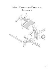
AFMG-48 SIDE VIEW PARTS DIAGRAM<br />
14<br />
15
BIRO MODEL AFMG-48-II MIXER GRINDER PARTS LIST<br />
Fig. Item No. Description<br />
1 57154 Product mixer safety cover, tri directional,<br />
#63592 on<br />
1A 53547 Lid with chute opening<br />
1B 53543 Conveyor chute<br />
2 56072 Safety cover latch<br />
3 56073 Safety cover latch mounting bracket, L.H.<br />
4 56074 Safety cover latch mounting bracket, R.H.<br />
5 AN20S Acorn nut, 3 8-16 (2 req.)<br />
6 RHS24S Round head screw, 1 4-20 1 2 (2 req.)<br />
HNNL15S Hex nut, nylok, 1 4-20 (2 req.)<br />
7 RHS31S Round head screw, 1 4-20 1<br />
HNNL15S Hex nut, nylok, 1 4-20<br />
8A 53456 Mixer paddle assembly, 1st grind, optional<br />
8B 53918 Mixer paddle assembly, 2nd grind,<br />
standard<br />
9 53953 Mixer drive shaft seal<br />
10 53516 Mixer paddle drive pin<br />
11 SSS10Z Drive pin set screw<br />
12 53594 Bearing for 53520 assembly<br />
13 53517-1 Thrust bearing<br />
14 53852 Lock arm assembly w/brgs.<br />
15 53568 Mixer paddle lock set screw<br />
16 57047 Wireway cover, #63401 on<br />
17 1116 Acorn nut, 10-32 (3 req.)<br />
18 SSS45S Meatguard mounting stud<br />
19 WN20S Wing nut<br />
20 52392 Meat guard splash shield<br />
21 HK48 Knife drive pin<br />
22 HP48 Bowl plate pin (3 req.)<br />
23 HR42/48 Bowl ring<br />
24 52106-CTN Bowl w/plate pins<br />
25 54278-CTN Auger assembly<br />
25B 54278B Square drive auger adapter<br />
25C 54278C Auger shear pin<br />
25D FHS33S Shear pin flat head screw, 1 4-20 ½<br />
26 53413 Bowl mounting stud – short (1 req.)<br />
HNF42S Hex flange nut, 1 2-13, (2 req.)<br />
26A 53413-2 Bowl mounting stud – long (2 req.)<br />
26B HNF42S Flange hex nut ½-13 bowl mounting nut<br />
(3 req.)<br />
27 57159K Auger drive shaft seal kit<br />
27A 57160 Seal retainer, SS<br />
27B 57159 Auger drive shaft seal, double lip<br />
27C FHS26S Flat head screw 10-32 3 4,SS<br />
28 53475-200 Motor, 7½HP, 200/400-60-3<br />
53475 Motor, 7 1 2HP, 208/460-60-3<br />
53475-50 Motor, 7½HP, 208/380-50-3<br />
53941 Motor, 7 1 2HP, 575-60-3<br />
53475-1 Baldor 7½HP, bearing both ends –<br />
206KDD<br />
53475-2 Doerr 7½HP, bearing, opp. shaft –<br />
206KDD<br />
53475-3 Doerr 7½HP, bearing, shaft end –<br />
207KDD<br />
57025-200 Motor, 10HP, 200/400-60-3<br />
57025 Motor, 10HP, 208/460-50/60-3<br />
57025-5 Motor, 10HP, 575-60-3<br />
57092 Motor, 10HP, 220/380-50-3<br />
29 53886 Journal box assembly<br />
30 H384-CL Roller chain<br />
31 54310 Adjusting stud<br />
32 55092 Rear drive cover w/handles<br />
55092-COSK Rear drive cover COS kit<br />
55092-COS Rear drive cover w/handles & magnet<br />
14688 4-point knob, AL<br />
14688-COS Locking knob, AL<br />
57219 Screw – COS rear drive cover<br />
FW05S Flat washer ¼, SS<br />
FW16S Flat washer 5 16, SS<br />
HHS025S Hex head screw ¼-20 ½, SS<br />
HHS049S Hex head screw 5 16-18 ½, SS<br />
HHS050S Hex head screw 5 16-18 5 8,SS<br />
16<br />
15<br />
Fig. Item No. Description<br />
HHS055S Hex head screw 5 16-18 ¾, SS<br />
HN07S Hex nut 10-24, SS<br />
HN15S Hex nut ¼-20, SS<br />
HN20S Hex nut 5 16-18, SS<br />
LW10S Lock washer ¼, SS<br />
LWE10P Lock washer #10 ext tooth, SS<br />
33 53478 Starter w/110V coil, Furnas size 1,<br />
14DP32AF81, 7 1 2HP<br />
55046 Starter w/24V coil, Furnas size 1,<br />
14DP32AJ71, 7½HP<br />
75DF14 Contact kit, Furnas 1 pole only (size 1)<br />
7½HP<br />
57027 Starter w/110V coil, Furnas size 1 3 4,<br />
14EP32AF81, 10HP<br />
57027CE Starter w/24V coil, Furnas size 1¾,<br />
14EP32AJ71, 10HP<br />
75EF14 Contact kit, Furnas 1 pole only (size 1¾)<br />
10HP<br />
33A 34478 Holding coil – 120V/240V<br />
55047 Holding coil – 24V<br />
34 53851 Fuse, FNM-1 AMP, 250V timedelay<br />
35 53914 Transformer, 230/460 to 115V<br />
53731 Transformer, 575 to 115V<br />
PC141-1 Transformer replacement,<br />
200/208/220/240/277/380 to 24V<br />
36 See electrical diagram, page 4<br />
37 53477 Starter w/110V coil, Furnas size 00,<br />
14BP32AF81, 1¾HP<br />
55045 Starter w/24V coil, Furnas size 00,<br />
14BG32AJ71, 1HP<br />
75BF14 Contact kit, Furnas 1 pole only (size 00)<br />
1HP<br />
37A 34478 Holding coil – 120V/240V<br />
55047 Holding coil – 24V<br />
38 53633 Starter box cover<br />
39 53860 Starter box<br />
40 52181-1 Magnetic switch bracket for magnet<br />
41 52181-1 Magnet w/mounting brkt. (110 volt)<br />
PC166 Magnetic safety switch (24 volt) old style<br />
units only (not CE)<br />
42 42MC-Y73 Green start button<br />
43 H442-1 Magni switch, 3 amp<br />
53872 Safety switch mounting bracket<br />
44 42MC-Y74 Red stop button<br />
45 50655-1 Switch guard<br />
H462-1 Switch guard ferrule<br />
HN20S Hex nut 5 16-18 SS<br />
LW15S Lock washer 5 16 SS<br />
46 54320K Toggle switch,hand/foot, w/boot<br />
47 54321 Toggle switch waterproof half boot<br />
48 53869CEK Legend plate, w/int’l. symbols, int'l kit<br />
49 53870 Legend plate gasket<br />
50 52655 Female receptacle, 5 pole, for footswitch<br />
51 52662 Protective cap assembly<br />
52 53872 Safety switch bracket<br />
53 35376 End anchor<br />
54 35241 Mounting channel<br />
55 35375 End barrier<br />
56 35374 Terminal block<br />
57 53783 Decal, rotation<br />
58 57156 Front splash shield<br />
HHS025S Hex head screw ¼-20 ½, SS<br />
HN15S Hex nut ¼-20, SS<br />
LW10S Lock washer ¼, SS<br />
NOT SHOWN<br />
57073 Power cord, 10’, 8-4<br />
54268 Power cord, 10’, 10-4<br />
2563 Legend plate hex screw<br />
10-32 1 2,SS<br />
53965 Optional leg ext. kit with brace
117
F<br />
18<br />
17
DORRIS MIXER TRANSMISSION PARTS LIST<br />
H369 Hex head screw 5 16-18 ¾<br />
LW30S Lockwasher, SS 1 2"<br />
0850 Setscrew 1 4-20 1 4" long<br />
1084 Hex head cap screw 1 2-13 1 1 4 long<br />
1103 Set screw 1 4-20 3 8" long<br />
SSS30 Set screw 3 8-24 3 4" long<br />
53516 Mixer drive pin<br />
53769 Mixer paddle transmission<br />
53769-01 Transmission housing<br />
53769-03 Cover plate<br />
53769-05 Low speed open cap<br />
53769-06 High speed closed cap<br />
53769-07 High speed open cap<br />
53769-08 Low speed shaft<br />
53769-09 Intermediate pinion gear<br />
53769-10 High speed pinion gear<br />
53769-11 Intermediate gear<br />
53769-12 Low speed gear<br />
53769-20 Intermediate closed cap<br />
53769-31 High speed shaft key<br />
53769-32 Intermediate gear key<br />
53769-33 Low speed gear key<br />
53769-35 Low speed shaft key<br />
53769-36 Low speed Timken cup<br />
53769-37 Low speed Timken cone<br />
53769-38 High speed Timken cup (closed end)<br />
53769-39 High speed Timken cone (closed end)<br />
53769-40 High speed Timken cup (open end)<br />
53769-41 High speed Timken cone (open end)<br />
53769-42 Intermediate Timken cup<br />
53769-43 Intermediate Timken cone<br />
53769-44 Intermediate spacer ring<br />
53769-45 Low speed spacer ring<br />
53769-46 High speed spacer ring<br />
53769-47 Puller shaft seal<br />
53769-57 Intermediate shims<br />
53769-58 High speed shims<br />
53769-59 Low speed shims<br />
53769-60 Cover plate gasket<br />
53769-61 High speed oil seal<br />
53769-62 Low speed oil seal<br />
53769-63 Hex screw (intermediate cap)<br />
53769-64 Hex screw (high speed cap)<br />
53769-69 Hex screw (low speed cap)<br />
53769-71 Hex screw (cover)<br />
53769-74 Breather plug<br />
53769-75 Magnetic drain plug<br />
53769-96 Grease fitting<br />
53953 Mixer drive shaft seal<br />
53955 Mixer drive shaft<br />
19<br />
18
NO. 53886 JOURNAL BOX ASSEMBLY<br />
20<br />
19<br />
Item No. Description<br />
53609 Journal box, #62001 on<br />
53724 Auger drive shaft, #62001 on<br />
53785 Journal box seal (2 ea.)<br />
53886 Journal box assembly complete<br />
53888, 53940 Front bearing cup/cone assembly<br />
Order H310A<br />
53889, 53939 Rear bearing cup/cone assembly<br />
Order H311A<br />
53993 Vented grease fitting<br />
FOOTSWITCH PARTS LIST<br />
224-2 Cord connector, wt, straight, 3 52654<br />
4"<br />
Male plug w/6’ cord, 5 wire<br />
52655 Female receptacle, 5 pole<br />
52661 Male plug w/12’ cord, 5 wire<br />
52668 Footswitch w/12’ cord and plug<br />
53693 Footswitch<br />
53693-A Cover guard<br />
53693-C Cover gasket<br />
53693-D Cover screw – short<br />
53693-E Cover screw – long<br />
53693-F Ground screw<br />
53693-G Treadle spring<br />
53693-H Internal assembly complete<br />
53693-I Actuator<br />
53693-M Micro switch BA-2R62-A4<br />
53693-O Washer<br />
53693-T Treadle w/actuator & return spring<br />
53693-U Auxiliary treadle return spring<br />
53693-W Treadle<br />
53693-X<br />
54213 53979-1<br />
54213<br />
One actuator & actuator spring assembly<br />
Foot Cordswitch 8’ w/o w/6’ foot cord switch & plug<br />
Foot switch w/6’ cord & plug
21<br />
20<br />
TANDEM OPERATION<br />
PARTS LIST<br />
272-7-1<br />
53489<br />
5<br />
16-18 plastic knob – 3 pt.<br />
Dscg. Horn 24/42/46/48 to 24/48/52<br />
inlet less seal<br />
57044 Connec. brkt. AFMG52 to AFMG48<br />
57044 Connec. brkt. AFMG52 to AFMG52<br />
53552-1A Connecting brkt. assem. man/auto<br />
53604 Dscg. horn 52 to 24/48/52 inlet<br />
53667 Dscg. horn 56 to 24/48/52 inlet<br />
53671 Seal only 24/42/46/48 to 24/48/52<br />
inlet<br />
53673 Disc. horn 48-52 w/seal<br />
53933 Seal only 52/56 to 24/48/52 inlet
TANDEM OPERATION ILLUSTRATION FOR 90° INLET<br />
FROM S/N 62001 TO S/N 63591<br />
21<br />
22
23<br />
22
CONNECTION INSTRUCTIONS<br />
TANDEM OPERATIONS<br />
AFMG-48 or ARFMG-52 INTO AFMG-48 or AFMG-52<br />
Heavy Horsepower Grinder INTO AFMG-48 or AFMG-52<br />
Remove Side Entrance Seal, Item No. 57133; Outer Disc, Item No. 54303 and<br />
Lock Knobs, Item No. 14688 from the inlet tube of the Second Grind Machine.<br />
Clean out the tube if necessary.<br />
Install the Inlet Tube Seal Item No. 53671 or 57145<br />
into the inlet tube of the Second Grind Machine until<br />
fully seated.<br />
Remove the Ring from the First Grind Machine, Item No. HR42/48 or HR52. Insert<br />
the Discharge Horn, Item No. 57144-7 or 57143-7 into the ring. (DO NOT<br />
reinstall the ring on the First Grind Machine at this time.) Slide the Clamp Assembly,<br />
Item No. 57144-11 or 57143-11 onto the Discharge Horn.<br />
Insert the Discharge Horn with Ring and Clamp Assembly<br />
into the Seal, pushing it fully against the inlet tube internal<br />
fins. Attach the lock latches to the tabs on the side of the<br />
inlet tube and lock down. Tighten the lock knob on the<br />
Clamp Assembly.<br />
Move the Discharge Horn of the Second Grind Machine up to the Bowl of the First<br />
Grind Machine. With the Auger, Knife and Grinding Plate installed in the First<br />
Grind Machine, thread the Ring onto the First Grind Machine Bowl. RING<br />
SHOULD BE HAND TIGHTENED ONLY: USE NO TOOLS.<br />
24<br />
23
TANDEM OPERATION ILLUSTRATION FOR 35° INLET<br />
S/N 63592 ON<br />
24<br />
25
OPERATOR’S SIGNATURE PAGE<br />
MY SIGNATURE ATTESTS THAT I HAVE COMPLETELY READ AND UNDERSTAND THIS<br />
MANUAL. I REALIZE THAT THIS MACHINE, IF OPERATED CARELESSLY, CAN CAUSE SE-<br />
RIOUS INJURY TO MYSELF AND OTHERS.<br />
NAME (PRINT) SIGNATURE SUPERVISOR’S<br />
INITIALS<br />
27<br />
26<br />
DATE
— NOTES —<br />
28<br />
27
LIMITED WARRANTY<br />
WARRANTY: The Biro Manufacturing Company warrants that the BIRO AFMG-48-II Mixer<br />
Grinder/Chopper will be free from defects in material and workmanship under normal use and with<br />
recommended service. BIRO will replace defective parts, which are covered by this limited warranty,<br />
provided that the defective parts are authorized for return, shipping charges prepaid, to a<br />
designated factory for inspection and/or testing.<br />
DURATION OF WARRANTY: The warranty period for all parts covered by this limited warranty is<br />
one (1) year from date of inspection/demonstration as advised on the returned Warranty registration<br />
card, or eighteen (18) months from original factory shipping date, whichever date occurs first,<br />
except as noted below.<br />
PARTS NOT COVERED BY WARRANTY: The following are not covered by this limited warranty:<br />
wearable parts in the grinding system such as bowl, ring, worm, drive shaft, and knife drive pin.<br />
This limited warranty does not apply to machines sold as used, rebuilt, modified, or altered from<br />
the original construction in which the machine was shipped from the factory. Water contaminated<br />
electrical systems are not covered under this limited warranty. BIRO is not responsible for electrical<br />
connection of equipment, adjustments to the switch controls or any other electrical requirements,<br />
which must be performed only by a certified electrician. BIRO is not responsible for service<br />
charges or labor required to replace any part covered by this limited warranty or for any damages<br />
resulting from misuse, abuse, lack of proper or recommended service.<br />
EXCLUSION OF WARRANTIES AND LIMITATION OF REMEDIES: BIRO gives no warranties<br />
other than those expressly stated in this limited warranty. THE IMPLIED WARRANTY OF MER-<br />
CHANTABILITY, THE IMPLIED WARRANTY OF FITNESS FOR PROCESSING OF FOOD PROD-<br />
UCTS, AND ALL OTHER IMPLIED WARRANTIES ARE SPECIFICALLY EXCLUDED. BIRO IS NOT<br />
LIABLE FOR CONSEQUENTIAL OR INCIDENTAL DAMAGES, EXPENSES, OR LOSSES. THE<br />
REMEDIES PROVIDED IN THIS BIRO LIMITED WARRANTY ARE PURCHASER’S SOLE AND EX-<br />
CLUSIVE REMEDIES AGAINST BIRO.<br />
REGISTRATION CARDS: You must sign, date and complete warranty registration card supplied<br />
with each machine. The warranty card must be returned to The Biro Manufacturing Company for<br />
proper registration. If no warranty card is returned to BIRO, the warranty period will begin from<br />
the date the machine was originally shipped from the factory.<br />
HOW TO GET SERVICE:<br />
1. Contact the entity from whom you purchased the machine; or<br />
2. Consult the yellow pages of the phone directory for the nearest authorized dealer; or<br />
3. Contact BIRO Mfg. Company for the authorized service entity (250 plus worldwide) in your area.<br />
ITEM NO: 53913<br />
PTCT AFMG 48-138-6-12-15 PPD<br />
ITEM NO: 53913<br />
PTCT AFMG 48-138-9-05-12 COMM<br />
THE BIRO MANUFACTURING COMPANY<br />
1114 Main Street<br />
Marblehead, Ohio<br />
Ph. 419-798-4451<br />
Fax 419-798-9106<br />
E-mail: service@biro saw.com<br />
Web: http://www.birosaw.com<br />
29<br />
28