Manual - Dfi
Manual - Dfi
Manual - Dfi

Create successful ePaper yourself
Turn your PDF publications into a flip-book with our unique Google optimized e-Paper software.
EL109-N<br />
System Board<br />
User’s <strong>Manual</strong><br />
935-EL1091-000G<br />
A11330048
Copyright<br />
This publication contains information that is protected by copyright. No part of it<br />
may be reproduced in any form or by any means or used to make any transformation/adaptation<br />
without the prior written permission from the copyright holders.<br />
This publication is provided for informational purposes only. The manufacturer<br />
makes no representations or warranties with respect to the contents or use<br />
of this manual and specifically disclaims any express or implied warranties of<br />
merchantability or fitness for any particular purpose. The user will assume the<br />
entire risk of the use or the results of the use of this document. Further, the<br />
manufacturer reserves the right to revise this publication and make changes to<br />
its contents at any time, without obligation to notify any person or entity of such<br />
revisions or changes.<br />
© 2010. All Rights Reserved.<br />
Trademarks<br />
All trademarks and registered trademarks of products appearing in this manual<br />
are the properties of their respective holders.
FCC and DOC Statement on Class B<br />
This equipment has been tested and found to comply with the limits for a Class B<br />
digital device, pursuant to Part 15 of the FCC rules. These limits are designed to<br />
provide reasonable protection against harmful interference when the equipment<br />
is operated in a residential installation. This equipment generates, uses and can<br />
radiate radio frequency energy and, if not installed and used in accordance with<br />
the instruction manual, may cause harmful interference to radio communications.<br />
However, there is no guarantee that interference will not occur in a particular<br />
installation. If this equipment does cause harmful interference to radio or television<br />
reception, which can be determined by turning the equipment off and on,<br />
the user is encouraged to try to correct the interference by one or more of the<br />
following measures:<br />
• Reorient or relocate the receiving antenna.<br />
• Increase the separation between the equipment and the receiver.<br />
• Connect the equipment into an outlet on a circuit different from that to which<br />
the receiver is connected.<br />
• Consult the dealer or an experienced radio TV technician for help.<br />
Notice:<br />
1. The changes or modifications not expressly approved by the party responsible<br />
for compliance could void the user’s authority to operate the equipment.<br />
2. Shielded interface cables must be used in order to comply with the emission<br />
limits.
1<br />
4<br />
Introduction<br />
Table of Contents<br />
Copyright ........................................................................................... 2<br />
Trademarks ........................................................................................ 2<br />
FCC and DOC Statement on Class B .............................................. 3<br />
About this <strong>Manual</strong> ............................................................................. 7<br />
Warranty .......................................................................................... 7<br />
Static Electricity Precautions ............................................................. 8<br />
Safety Measures ................................................................................. 8<br />
About the Package ............................................................................ 9<br />
Before Using the System Board ........................................................ 9<br />
Chapter 1 - Introduction ................................................................ 10<br />
Specifications ................................................................................ 10<br />
Features ...................................................................................... 12<br />
Chapter 2 - Hardware Installation .................................................. 15<br />
System Board Layout .................................................................... 15<br />
System Memory ........................................................................... 16<br />
Installing the DIM Module ......................................................... 17<br />
CPU ............................................................................................ 19<br />
Installing the CPU .................................................................... 19<br />
Installing the Fan and Heat Sink ................................................ 23<br />
Jumper Settings ............................................................................. 25<br />
Clear CMOS Data ..................................................................... 25<br />
PS/2 Power Select .................................................................... 26<br />
USB Power Select ..................................................................... 27<br />
Rear Panel I/O Ports ..................................................................... 28<br />
PS/2 Mouse and PS/2 Keyboard Ports ......................................... 29<br />
COM (Serial) Ports ................................................................... 30<br />
VGA Port ................................................................................. 31<br />
DVI-I Port ............................................................................... 32<br />
USB Ports................................................................................ 33<br />
RJ45 LAN Ports ........................................................................ 35<br />
Audio ..................................................................................... 36
Introduction<br />
I/O Connectors ............................................................................ 37<br />
SATA (Serial ATA) Connectors .................................................... 37<br />
Cooling Fan Connectors ............................................................. 38<br />
Chassis Instrusion Connector .................................................... 39<br />
Power Connectors .................................................................... 40<br />
Standby Power LED .................................................................. 41<br />
Front Panel Connectors ............................................................. 42<br />
Expansion Slots ....................................................................... 43<br />
Battery ................................................................................... 44<br />
Chapter 3 - BIOS Setup .................................................................. 45<br />
Award BIOS Setup Utility .............................................................. 45<br />
Standard CMOS Features .......................................................... 46<br />
Advanced BIOS Features ........................................................... 50<br />
Advanced Chipset Features ........................................................ 56<br />
Integrated Peripherals .............................................................. 58<br />
Power Management Setup ......................................................... 66<br />
PnP/PCI Configurations ............................................................. 69<br />
PC Health Status ...................................................................... 71<br />
Frequency/Voltage Control ........................................................ 73<br />
Load Fail-Safe Defaults ............................................................. 74<br />
Load Optimized Defaults ........................................................... 75<br />
Set Supervisor Password ........................................................... 76<br />
Set User Password ................................................................... 77<br />
Save & Exit Setup .................................................................... 78<br />
Exit Without Saving .................................................................. 79<br />
Updating the BIOS ........................................................................ 80<br />
Chapter 4 - Supported Software ................................................... 82<br />
Drivers, Utilities and Software Applications.................................................82<br />
Intel Chipset Software Installation Utility .................................... 83<br />
Microsoft DirectX 9.0C Driver .................................................... 85<br />
Intel Graphics Drivers ............................................................... 86<br />
Audio Drivers ........................................................................... 88<br />
LAN Drivers ............................................................................. 90<br />
Hardware Monitor for Windows .................................................. 92<br />
Installation Notes ............................................................................................... 94<br />
1<br />
5
1<br />
6<br />
Introduction<br />
Appendix A - Watchdog Sample Code ........................................... 95<br />
Appendix B - System Error Message .............................................. 97<br />
Appendix C - Troubleshooting ........................................................ 99
About this <strong>Manual</strong><br />
Introduction<br />
An electronic file of this manual is included in the CD. To view the user’s manual<br />
in the CD, insert the CD into a CD-ROM drive. The autorun screen (Main Board<br />
Utility CD) will appear. Click “User’s <strong>Manual</strong>” on the main menu.<br />
Warranty<br />
1. Warranty does not cover damages or failures that arised from misuse of the<br />
product, inability to use the product, unauthorized replacement or alteration<br />
of components and product specifications.<br />
2. The warranty is void if the product has been subjected to physical abuse,<br />
improper installation, modification, accidents or unauthorized repair of the<br />
product.<br />
3. Unless otherwise instructed in this user’s manual, the user may not, under<br />
any circumstances, attempt to perform service, adjustments or repairs on the<br />
product, whether in or out of warranty. It must be returned to the purchase<br />
point, factory or authorized service agency for all such work.<br />
4. We will not be liable for any indirect, special, incidental or consequencial<br />
damages to the product that has been modified or altered.<br />
1<br />
7
1<br />
8<br />
Introduction<br />
Static Electricity Precautions<br />
It is quite easy to inadvertently damage your PC, system board, components<br />
or devices even before installing them in your system unit. Static electrical discharge<br />
can damage computer components without causing any signs of physical<br />
damage. You must take extra care in handling them to ensure against electrostatic<br />
build-up.<br />
1. To prevent electrostatic build-up, leave the system board in its anti-static bag<br />
until you are ready to install it.<br />
2. Wear an antistatic wrist strap.<br />
3. Do all preparation work on a static-free surface.<br />
4. Hold the device only by its edges. Be careful not to touch any of the components,<br />
contacts or connections.<br />
5. Avoid touching the pins or contacts on all modules and connectors. Hold<br />
modules or connectors by their ends.<br />
Important:<br />
Electrostatic discharge (ESD) can damage your processor, disk drive and<br />
other components. Perform the upgrade instruction procedures described<br />
at an ESD workstation only. If such a station is not available, you can<br />
provide some ESD protection by wearing an antistatic wrist strap and<br />
attaching it to a metal part of the system chassis. If a wrist strap is<br />
unavailable, establish and maintain contact with the system chassis<br />
throughout any procedures requiring ESD protection.<br />
Safety Measures<br />
To avoid damage to the system:<br />
• Use the correct AC input voltage range.<br />
To reduce the risk of electric shock:<br />
• Unplug the power cord before removing the system chassis cover for installation<br />
or servicing. After installation or servicing, cover the system chassis<br />
before plugging the power cord.<br />
Battery:<br />
• Danger of explosion if battery incorrectly replaced.<br />
• Replace only with the same or equivalent type recommend by the manufacturer.<br />
• Dispose of used batteries according to local ordinance.
About the Package<br />
Introduction<br />
The system board package contains the following items. If any of these items are<br />
missing or damaged, please contact your dealer or sales representative for assistance.<br />
One system board<br />
One COM cable<br />
One USB cable<br />
Two Serial ATA data cables<br />
Two Serial ATA power cables<br />
One I/O shield<br />
One user’s manual<br />
One CD<br />
One QR (Quick Reference)<br />
The system board and accessories in the package may not come similar to the<br />
information listed above. This may differ in accordance to the sales region or<br />
models in which it was sold. For more information about the standard package in<br />
your region, please contact your dealer or sales representative.<br />
Before Using the System Board<br />
Before using the system board, prepare basic system components.<br />
If you are installing the system board in a new system, you will need at least the<br />
following internal components.<br />
• A CPU<br />
• Memory module<br />
• Storage devices such as hard disk drive, CD-ROM, etc.<br />
You will also need external system peripherals you intend to use which will normally<br />
include at least a keyboard, a mouse and a video display monitor.<br />
1<br />
9
1<br />
10<br />
Introduction<br />
Chapter 1 - Introduction<br />
Specifications<br />
Processor<br />
Chipset<br />
System Memory<br />
Expansion Slots<br />
Graphics<br />
Audio<br />
LAN<br />
Serial ATA<br />
Rear Panel I/O<br />
Ports<br />
• LGA 775 socket for:<br />
- Intel ® Core TM2 Quad Q9400<br />
- Intel ® Core TM2 Duo E8400/E7400/E6400/E4300<br />
- Intel ® Pentium ® E6500/E5300/E2160<br />
- Intel ® Celeron ® E3400/E1500/440<br />
• Supports Intel Enhanced Memory 64 Technology (EMT64T)<br />
• Supports Enhanced Intel SpeedStep Technology (EIST)<br />
• 800/1066/1333MHz FSB<br />
• Intel ® chipset<br />
- Intel ® G41 Express chipset<br />
- Intel ® ICH7 I/O Controller Hub<br />
• One DDR3 DIMM socket<br />
• Supports single channel memory interface<br />
• 800/1066 MHz DDR3 SDRAM<br />
• Maximum of 2GB system memory<br />
• 1 PCI Express x1 slot<br />
• Integrated Intel GMA X4500<br />
- Supports 3D, 2D and video capabilities, DX10 and<br />
OpenGL 1.5<br />
• Realtek ALC662 High Definition audio CODEC<br />
• Six channel DAC supports 16/20/24-bit PCM format for 5.1<br />
channel audio solution<br />
• All DAC support independent 44.1k/48k/96kHz sample rate<br />
• All ADC support independent 44.1k/48k/96kHz sample rate<br />
• Two Realtek RTL8111DL PCI Express Gigabit controllers<br />
• Supports 10Mbps, 100Mbps and 1Gbps data transmission<br />
• IEEE 802.3 (10/100Mbps) and IEEE 802.3ab (1Gbps) compliant<br />
• Supports 4 SATA (Serial ATA) interfaces which are compliant<br />
with SATA 1.0 specification<br />
• SATA speed up to 3Gb/s<br />
• 1 mini-DIN-6 PS/2 mouse port<br />
• 1 mini-DIN-6 PS/2 keyboard port<br />
• 2 DB-9 RS232 serial ports<br />
• 1 DB-15 VGA port<br />
• 1 DVI-I port (DVI-D signal only)<br />
• 2 RJ45 LAN ports<br />
• 4 USB 2.0/1.1 ports<br />
• Mic-in, line-in and line-out
I/O Connectors<br />
BIOS<br />
Energy Efficient<br />
Design<br />
Damage Free<br />
Intelligence<br />
Temperature<br />
Humidity<br />
PCB<br />
Introduction<br />
• 2 connectors for 4 additional external USB 2.0/1.1 ports<br />
• 2 connectors for 2 external RS232 serial ports<br />
• 1 front audio connector<br />
• 4 Serial ATA connectors<br />
• 1 20-pin ATX power connector<br />
• 1 4-pin 12V power connector<br />
• 1 chassis open connector<br />
• 1 front panel connector<br />
• 2 fan connectors<br />
• Award BIOS<br />
• 8Mbit SPI BIOS<br />
• ACPI specification and OS Directed Power Management<br />
• Supports ACPI STR (Suspend to RAM) function<br />
• Wake-On-Events include:<br />
- Wake-On-PS/2 Keyboard/Mouse<br />
- Wake-On-USB Keyboard/Mouse<br />
- Wake-On-LAN<br />
- Wake-On-Ring<br />
- RTC timer to power-on the system<br />
• System power management supported<br />
• Microsoft ® /Intel ® APM 1.2 compliant<br />
• Soft Power supported - ACPI v1.0a specification<br />
• AC power failure recovery<br />
• Monitors CPU/system temperature and overheat alarm<br />
• Monitors CPU/DIMM/3.3V/5V/12V/V5sb/VBAT voltages and<br />
failure alarm<br />
• Monitors CPU/system fan speed and failure alarm<br />
• Read back capability that displays temperature, voltage and<br />
fan speed<br />
• Watchdog timer function<br />
• 0 o C to 60 o C<br />
• 10% to 90%<br />
• 8-layers, Mini-ITX form factor<br />
• 170mm (6.7”) x 170mm (6.7”)<br />
1<br />
11
1<br />
12<br />
Introduction<br />
Features<br />
Watchdog Timer<br />
The Watchdog Timer function allows your application to regularly “clear” the system<br />
at the set time interval. If the system hangs or fails to function, it will reset<br />
at the set time interval so that your system will continue to operate.<br />
DDR3<br />
DDR3 delivers increased system bandwidth and improved performance. It offers<br />
peak data transfer rate of up to 21 Gb/s bandwidth. The advantages of DDR3<br />
are its higher bandwidth and its increase in performance at a lower power than<br />
DDR2.<br />
Graphics<br />
The Intel northbridge chip comes integrated with the Intel Graphics Media Accelerator<br />
X4500 delivering 3D, 2D and video capabilities. With support for Microsoft<br />
DirectX 10 and OpenGL 2.1, Intel GMA X4500 delivers excellent video and 3D<br />
graphics with outstanding graphics responsiveness. These enhancements deliver<br />
the performance and compatibility needed for today’s and tomorrow’s business<br />
applications.<br />
PCI Express<br />
PCI Express is a high bandwidth I/O infrastructure that possesses the ability to<br />
scale speeds by forming multiple lanes. The x1 PCI Express lane supports transfer<br />
rate of 2.5 Gigabytes (250MBbps) per second.<br />
Audio<br />
The Realtek ALC662 audio codec provides 6-channel audio output for advanced<br />
5.1-channel super surround sound audio system.<br />
Serial ATA<br />
Serial ATA is a storage interface that is compliant with SATA 1.0a specification.<br />
With speed of up to 3Gbps, it improves hard drive performance faster than the<br />
standard parallel ATA whose data transfer rate is 100MB/s.<br />
Gigabit LAN<br />
The two Realtek RTL8111DL PCI Express Gigabit controllers support up to 1Gbps<br />
data transmission.
USB<br />
Introduction<br />
The system board supports USB 2.0 and USB 1.1 ports. USB 1.1 supports 12Mb/<br />
second bandwidth while USB 2.0 supports 480Mb/second bandwidth providing a<br />
marked improvement in device transfer speeds between your computer and a<br />
wide range of simultaneously accessible external Plug and Play peripherals.<br />
Wake-On-Ring<br />
This feature allows the system that is in the Suspend mode or Soft Power Off<br />
mode to wake-up/power-on to respond to calls coming from an external modem<br />
or respond to calls from a modem PCI card that uses the PCI PME (Power Management<br />
Event) signal to remotely wake up the PC.<br />
Important:<br />
The 5V_standby power source of your power supply must support<br />
≥720mA.<br />
Wake-On-LAN<br />
This feature allows the network to remotely wake up a Soft Power Down (Soft-<br />
Off) PC. It is supported via the onboard LAN port or via a PCI LAN card that uses<br />
the PCI PME (Power Management Event) signal. However, if your system is in the<br />
Suspend mode, you can power-on the system only through an IRQ or DMA interrupt.<br />
Important:<br />
The 5V_standby power source of your power supply must support<br />
≥720mA.<br />
Wake-On-PS/2<br />
This function allows you to use the PS/2 keyboard or PS/2 mouse to power-on<br />
the system.<br />
Important:<br />
The 5V_standby power source of your power supply must support<br />
≥720mA.<br />
Wake-On-USB<br />
This function allows you to use a USB keyboard or USB mouse to wake up a system<br />
from the S3 (STR - Suspend To RAM) state.<br />
Important:<br />
If you are using the Wake-On-USB Keyboard/Mouse function for 2 USB<br />
ports, the 5V_standby power source of your power supply must support<br />
≥1.5A. For 3 or more USB ports, the 5V_standby power source of your<br />
power supply must support ≥2A.<br />
1<br />
13
1<br />
14<br />
Introduction<br />
RTC Timer<br />
The RTC installed on the system board allows your system to automatically power-on<br />
on the set date and time.<br />
ACPI STR<br />
The system board is designed to meet the ACPI (Advanced Configuration and<br />
Power Interface) specification. ACPI has energy saving features that enables PCs<br />
to implement Power Management and Plug-and-Play with operating systems that<br />
support OS Direct Power Management. ACPI when enabled in the Power Management<br />
Setup will allow you to use the Suspend to RAM function.<br />
With the Suspend to RAM function enabled, you can power-off the system at<br />
once by pressing the power button or selecting “Standby” when you shut down<br />
Windows ® without having to go through the sometimes tiresome process of<br />
closing files, applications and operating system. This is because the system is<br />
capable of storing all programs and data files during the entire operating session<br />
into RAM (Random Access Memory) when it powers-off. The operating session will<br />
resume exactly where you left off the next time you power-on the system.<br />
Important:<br />
The 5V_standby power source of your power supply must support<br />
≥720mA.<br />
Power Failure Recovery<br />
When power returns after an AC power failure, you may choose to either poweron<br />
the system manually or let the system power-on automatically.
Chapter 2 - Hardware Installation<br />
System Board Layout<br />
KB<br />
Mouse<br />
COM 1<br />
COM 2<br />
VGA<br />
DVI-I<br />
LAN 1<br />
USB 1<br />
USB 0<br />
LAN 2<br />
USB 3<br />
USB 2<br />
Mic-in<br />
Line-in<br />
Line-out<br />
1<br />
1<br />
1<br />
1<br />
PS/2 power<br />
select ( JP6)<br />
COM 3<br />
COM 4<br />
DVI-I port (DVI-D signal only)<br />
1<br />
+12V<br />
power<br />
1<br />
1<br />
Front audio<br />
Chassis<br />
intrusion<br />
CPU fan<br />
1<br />
USB 0-3 power<br />
select ( JP3)<br />
USB 4-7 power<br />
select ( JP2)<br />
USB 4-5<br />
1<br />
1<br />
Intel<br />
ICH7<br />
USB 6-7<br />
SATA 4<br />
SPI<br />
Flash BIOS<br />
Standby<br />
1<br />
Power LED<br />
Clear CMOS<br />
1<br />
( JP5)<br />
PCIe x1<br />
SATA 3<br />
SATA 2<br />
SATA 1<br />
1<br />
1<br />
1<br />
1<br />
LGA 775<br />
Hardware Installation<br />
Intel<br />
G41<br />
10<br />
1 11<br />
ATX power<br />
Front panel<br />
20<br />
System fan<br />
1<br />
Battery<br />
DDR 3<br />
1<br />
2<br />
15
2 Hardware Installation<br />
16<br />
Important:<br />
Electrostatic discharge (ESD) can damage your system board, processor,<br />
disk drives, add-in boards, and other components. Perform the upgrade<br />
instruction procedures described at an ESD workstation only. If such a<br />
station is not available, you can provide some ESD protection by wearing<br />
an antistatic wrist strap and attaching it to a metal part of the system<br />
chassis. If a wrist strap is unavailable, establish and maintain contact<br />
with the system chassis throughout any procedures requiring ESD protection.<br />
System Memory<br />
1<br />
The DIMM socket supports DDR3 memory module.<br />
DIMM
Installing the DIM Module<br />
Hardware Installation<br />
Note:<br />
The system board used in the following illustrations may not resemble<br />
the actual board. These illustrations are for reference only.<br />
1. Make sure the PC and all other peripheral devices connected to it has been<br />
powered down.<br />
2. Disconnect all power cords and cables.<br />
3. Locate the DIMM socket on the system board.<br />
4. Push the “ejector tabs” which are at the ends of the socket to the side.<br />
Ejector tab<br />
5. Note how the module is keyed to the socket.<br />
Key<br />
Notch<br />
Ejector tab<br />
2<br />
17
2 Hardware Installation<br />
18<br />
6. Grasping the module by its edges, position the module above the socket with<br />
the “notch” in the module aligned with the “key” on the socket. The keying<br />
mechanism ensures the module can be plugged into the socket in only one<br />
way.<br />
7. Seat the module vertically, pressing it down firmly until it is completely seated<br />
in the socket.<br />
8. The ejector tabs at the ends of the socket will automatically snap into the<br />
locked position to hold the module in place.
CPU<br />
Hardware Installation<br />
The system board is equipped with a surface mount LGA 775 socket. This socket<br />
is exclusively designed for installing a LGA 775 packaged Intel CPU.<br />
Important:<br />
1. Before you proceed, make sure (1) the LGA775 socket comes with a<br />
protective cap, (2) the cap is not damaged and (3) the socket’s contact<br />
pins are not bent. If the cap is missing or the cap and/or contact<br />
pins are damaged, contact your dealer immediately.<br />
2. Make sure to keep the protective cap. RMA requests will be accepted<br />
and processed only if the LGA775 socket comes with the protective<br />
cap.<br />
Installing the CPU<br />
1. Make sure the PC and all other peripheral devices connected to it has been<br />
powered down.<br />
2. Disconnect all power cords and cables.<br />
3. Locate the LGA 775 CPU<br />
socket on the system<br />
board.<br />
Important:<br />
The CPU socket must not<br />
come in contact with anything<br />
other than the CPU.<br />
Avoid unnecessary exposure.<br />
Remove the protective<br />
cap only when you are<br />
about to install the CPU.<br />
1<br />
2<br />
19
2 Hardware Installation<br />
20<br />
4. The CPU socket comes<br />
with a removable protective<br />
cap. The cap is used<br />
to protect the CPU socket<br />
against dust and harmful<br />
particles. Remove the<br />
protective cap only when<br />
you are about to install the<br />
CPU.<br />
5. To remove the protective<br />
cap, lift the cap on the location<br />
pointed on the right<br />
photo.<br />
6. Unlock the socket by pushing<br />
the load lever down,<br />
moving it sideways until it<br />
is released from the retention<br />
tab; then lift it up.<br />
7. Life the load plate.<br />
Retention tab<br />
Load plate<br />
Protective cap<br />
Lift this part up<br />
Load lever
8. Position the CPU above the<br />
socket. The gold mark on<br />
the CPU must align with<br />
pin 1 of the CPU socket.<br />
Important:<br />
Handle the CPU by its edges<br />
and avoid touching the<br />
pins.<br />
9. Insert the CPU into the<br />
socket until it is seated<br />
in place. The CPU will fit<br />
in only one orientation<br />
and can easily be inserted<br />
without exerting any force.<br />
Important:<br />
Do not force the CPU into<br />
the socket. Forcing the<br />
CPU into the socket may<br />
bend the pins and damage<br />
the CPU.<br />
Hardware Installation<br />
Gold mark<br />
CPU<br />
Pin 1<br />
of the<br />
socket<br />
2<br />
21
2 Hardware Installation<br />
22<br />
10. Close the load plate.<br />
11. Push the load lever down<br />
to lock the socket. The<br />
lever should hook onto the<br />
retention tab to indicate<br />
that the CPU is completely<br />
secured in the socket.<br />
Load lever<br />
Load plate<br />
Retention tab
Installing the Fan and Heat Sink<br />
Hardware Installation<br />
The CPU must be kept cool by using a CPU fan with heat sink. Without sufficient<br />
air circulation across the CPU and heat sink, the CPU will overheat damaging both<br />
the CPU and system board.<br />
Note:<br />
A boxed Intel ® processor already includes the CPU fan and heat sink assembly.<br />
If your CPU was purchased separately, make sure to only use<br />
Intel ® -certified fan and heat sink.<br />
1. Before you install the fan / heat sink, you must apply a thermal paste onto<br />
the top of the CPU. The thermal paste is usually supplied when you purchase<br />
the fan / heat sink assembly. Do not spread the paste all over the surface.<br />
When you later place the heat sink on top of the CPU, the compound will disperse<br />
evenly.<br />
Some heat sinks come with a patch of pre-applied thermal paste. Do not apply<br />
thermal paste if the fan / heat sink already has a patch of thermal paste<br />
on its underside. Peel the strip that covers the paste before you place the fan<br />
/ heat sink on top of the CPU.<br />
2. Place the heat sink on top<br />
of the CPU. The 4 pushpins<br />
around the heat sink,<br />
which are used to secure<br />
the heat sink onto the system<br />
board, must match the<br />
4 mounting holes around<br />
the socket.<br />
3. Orient the heat sink such<br />
that the CPU fan’s cable is<br />
nearest the CPU fan connector.<br />
1<br />
1<br />
Mounting<br />
hole<br />
CPU fan<br />
connector<br />
2<br />
23
2 Hardware Installation<br />
24<br />
4. Rotate each push-pin according<br />
to the direction of<br />
the arrow shown on top of<br />
the pin.<br />
Push down two pushpins<br />
that are diagonally across<br />
the heat sink. Perform the<br />
same procedure for the<br />
other two push-pins.<br />
Push pin<br />
Fan<br />
Heat sink<br />
5. Connect the CPU fan’s cable connector to the CPU fan connector on the system<br />
board.
Jumper Settings<br />
Clear CMOS Data<br />
1<br />
If you encounter the following,<br />
a) CMOS data becomes corrupted.<br />
b) You forgot the supervisor or user password.<br />
Hardware Installation<br />
you can reconfigure the system with the default values stored in the ROM BIOS.<br />
To load the default values stored in the ROM BIOS, please follow the steps below.<br />
1. Power-off the system and unplug the power cord.<br />
2. Set JP5 pins 2 and 3 to On. Wait for a few seconds and set JP5 back to its<br />
default setting, pins 1 and 2 On.<br />
JP5<br />
3. Now plug the power cord and power-on the system.<br />
1 2 3<br />
1 2<br />
3<br />
1-2 On: Normal<br />
(default)<br />
2-3 On:<br />
Clear CMOS Data<br />
2<br />
25
2 Hardware Installation<br />
26<br />
PS/2 Power Select<br />
1<br />
JP6 is used to select the power of the PS/2 keyboard/mouse port. Selecting<br />
5V_standby will allow you to use the PS/2 keyboard or PS/2 mouse to wake up<br />
the system.<br />
BIOS Setting<br />
Configure the PS/2 keyboard/mouse wake up function in the Integrated Peripherals<br />
submenu (“Super IO Device” section) of the BIOS. Refer to chapter 3 for<br />
more information.<br />
Important:<br />
The 5VSB power source of your power supply must support ≥720mA.<br />
JP6<br />
1 2 3 1 2 3<br />
1-2 On: 5V<br />
(default)<br />
2-3 On:<br />
5V_standby
USB Power Select<br />
1<br />
Hardware Installation<br />
These jumpers are used to select the power of the USB ports. Selecting 5V_<br />
standby will allow you to use a USB device to wake up the system.<br />
BIOS Setting<br />
USB 0-3<br />
(JP3)<br />
USB 4-7<br />
(JP2)<br />
“USB KB Wake-Up From S3” in the Power Management Setup submenu of the<br />
BIOS must be set to Enabled. Refer to chapter 3 for more information.<br />
Important:<br />
If you are using the Wake-On-USB Keyboard/Mouse function for 2 USB<br />
ports, the 5V_standby power source of your power supply must support<br />
≥1.5A. For 3 or more USB ports, the 5V_standby power source of your<br />
power supply must support ≥2A.<br />
1<br />
2 3 1 2 3<br />
1-2 On: 5V<br />
(default)<br />
1 2 3 1 2 3<br />
1-2 On: 5V<br />
(default)<br />
2-3 On:<br />
5V_standby<br />
2-3 On:<br />
5V_standby<br />
2<br />
27
2 Hardware Installation<br />
28<br />
Rear Panel I/O Ports<br />
PS/2<br />
Mouse<br />
PS/2 K/B<br />
COM 1<br />
COM 2<br />
The rear panel I/O ports consist of the following:<br />
• PS/2 mouse port<br />
• PS/2 keyboard port<br />
• COM ports<br />
• VGA port<br />
• DVI-I port (DVI-D signal only)<br />
• LAN ports<br />
• 4 USB ports<br />
• Mic-in jack<br />
• Line-in jack<br />
• Line-out jack<br />
VGA<br />
DVI-I<br />
LAN 1<br />
LAN 2<br />
USB 0-1 USB 2-3<br />
Mic-in<br />
Line-in<br />
Line-out
PS/2 Mouse and PS/2 Keyboard Ports<br />
PS/2 Mouse<br />
PS/2 KB<br />
1<br />
Hardware Installation<br />
These ports are used to connect a PS/2 mouse and a PS/2 keyboard. The PS/2<br />
mouse port uses IRQ12. If a mouse is not connected to this port, the system will<br />
reserve IRQ12 for other expansion cards.<br />
Important:<br />
Make sure to turn off your computer prior to connecting or disconnecting<br />
a mouse or keyboard. Failure to do so may damage the system board.<br />
Wake-On-PS/2 Keyboard/Mouse<br />
The Wake-On-PS/2 Keyboard/Mouse function allows you to use the PS/2 keyboard<br />
or PS/2 mouse to power-on the system. To use this function:<br />
• Jumper Setting<br />
JP6 must be set to “2-3 On: 5V_standby”. Refer to “PS/2 Power Select” in<br />
this chapter for more information.<br />
• BIOS Setting<br />
Configure the PS/2 keyboard/mouse wake up function in the Integrated Peripherals<br />
submenu (“Super IO Device” section) of the BIOS. Refer to chapter<br />
3 for more information.<br />
Important:<br />
The 5V_standby power source of your power supply must support<br />
≥720mA.<br />
2<br />
29
2 Hardware Installation<br />
30<br />
COM (Serial) Ports<br />
COM 1<br />
COM 2<br />
DCD-<br />
RD<br />
TD<br />
DTR-<br />
GND<br />
1 2 3 4 5<br />
6 7 8 9<br />
DSR-<br />
RTS-<br />
CTS-<br />
RI-<br />
COM 1 / COM 2<br />
The serial ports are RS232 asynchronous communication ports with 16C550Acompatible<br />
UARTs that can be used with modems, serial printers, remote display<br />
terminals, and other serial devices.<br />
Connecting an External Serial Port<br />
Your COM port may come mounted on a card-edge bracket. Install the card-edge<br />
bracket to an available slot at the rear of the system chassis then insert the serial<br />
port cable to the COM 3 or COM 4 connector. Make sure the colored stripe on<br />
the ribbon cable is aligned with pin 1 of the COM connector.<br />
BIOS Setting<br />
COM 3<br />
COM 4<br />
1<br />
CTS-<br />
DSR-<br />
COM 3 / COM 4<br />
Configure the serial ports in the Integrated Peripherals submenu (“Super IO Device”<br />
section) of the BIOS. Refer to chapter 3 for more information.<br />
DTR-<br />
RD<br />
9<br />
2 1<br />
RI-<br />
RTS-<br />
GND<br />
TD<br />
DCD-
VGA Port<br />
1<br />
Hardware Installation<br />
The VGA port is used for connecting a VGA monitor. Connect the monitor’s 15-pin<br />
D-shell cable connector to the VGA port. After you plug the monitor’s cable connector<br />
into the VGA port, gently tighten the cable screws to hold the connector<br />
in place.<br />
BIOS Setting<br />
VGA<br />
Configure the onboard VGA in the Advanced Chipset Features submenu of the<br />
BIOS. Refer to chapter 3 for more information.<br />
Driver Installation<br />
Install the graphics driver. Refer to chapter 4 for more information.<br />
2<br />
31
2 Hardware Installation<br />
32<br />
DVI-I Port<br />
DVI-I<br />
1<br />
The DVI-I port is used to connect an LCD monitor. This port supports DVI-D signal<br />
only.<br />
Connect the display device’s cable connector to the DVI-I port. After you plug the<br />
cable connector into the port, gently tighten the cable screws to hold the connector<br />
in place.<br />
BIOS Setting<br />
Configure the display device in the Advanced Chipset Features submenu of the<br />
BIOS. Refer to chapter 3 for more information.
USB Ports<br />
USB 1<br />
USB 0<br />
USB 3<br />
USB 2<br />
1<br />
Hardware Installation<br />
USB allows data exchange between your computer and a wide range of simultaneously<br />
accessible external Plug and Play peripherals.<br />
The system board is equipped with four onboard USB 2.0/1.1 ports. The two<br />
10-pin connectors allow you to connect 4 additional USB 2.0/1.1 ports. The additional<br />
USB ports may be mounted on a card-edge bracket. Install the card-edge<br />
bracket to an available slot at the rear of the system chassis then insert the USB<br />
port cables to a connector.<br />
BIOS Setting<br />
Configure the onboard USB in the Integrated Peripherals submenu (“USB Device<br />
Setting” section) of the BIOS. Refer to chapter 3 for more information.<br />
Driver Installation<br />
USB 4-5<br />
USB 6-7<br />
10 9<br />
N. C.<br />
Key<br />
GND<br />
+Data<br />
-Data<br />
You may need to install the proper drivers in your operating system to use the<br />
USB device. Refer to your operating system’s manual or documentation for more<br />
information.<br />
VCC<br />
2 1<br />
GND<br />
+Data<br />
-Data<br />
VCC<br />
2<br />
33
2 Hardware Installation<br />
34<br />
Wake-On-USB Keyboard/Mouse<br />
The Wake-On-USB Keyboard/Mouse function allows you to use a USB keyboard or<br />
USB mouse to wake up a system from the S3 (STR - Suspend To RAM) state. To<br />
use this function:<br />
• Jumper Setting<br />
JP2 and/or JP3 must be set to “2-3 On: 5V_standby”. Refer to “USB Power<br />
Select” in this chapter for more information.<br />
• BIOS Setting<br />
“USB KB Wake-Up From S3” in the Power Management Setup submenu of the<br />
BIOS must be set to Enabled. Refer to chapter 3 for more information.<br />
Important:<br />
If you are using the Wake-On-USB Keyboard/Mouse function for 2 USB<br />
ports, the 5V_standby power source of your power supply must support<br />
≥1.5A. For 3 or more USB ports, the 5V_standby power source of your<br />
power supply must support ≥2A.
RJ45 LAN Ports<br />
LAN 1<br />
LAN 2<br />
Hardware Installation<br />
The LAN ports allow the system board to connect to a local area network by<br />
means of a network hub.<br />
BIOS Setting<br />
Configure the onboard LAN in the Integrated Peripherals submenu of the BIOS.<br />
Refer to chapter 3 for more information.<br />
Driver Installation<br />
Install the LAN drivers. Refer to chapter 4 for more information.<br />
1<br />
2<br />
35
2 Hardware Installation<br />
36<br />
Audio<br />
Mic-in<br />
Line-in<br />
Line-out<br />
Rear Audio<br />
Rear audio<br />
1<br />
Front audio<br />
The system board is equipped with 3 audio jacks. A jack is a one-hole connecting<br />
interface for inserting a plug.<br />
• Mic-in Jack (Pink)<br />
This jack is used to connect an external microphone.<br />
• Line-in Jack (Light Blue)<br />
This jack is used to connect any audio devices such as Hi-fi set, CD player,<br />
tape player, AM/FM radio tuner, synthesizer, etc.<br />
• Line-out Jack (Lime)<br />
This jack is used to connect a headphone or external speakers.<br />
Front Audio<br />
The front audio connector allows you to connect to the second line-out and micin<br />
jacks that are at the front panel of your system.<br />
Driver Installation<br />
Install the audio driver. Refer to chapter 4 for more information.<br />
GND<br />
Presence Signal<br />
Mic2-JD<br />
Key<br />
Line2-JD<br />
2 10<br />
1<br />
9<br />
Mic2-L<br />
Mic2-R<br />
Line2-R<br />
Front_IO_Sense<br />
Line2-L
I/O Connectors<br />
SATA (Serial ATA) Connectors<br />
1<br />
Hardware Installation<br />
The Serial ATA connectors are used to connect Serial ATA devices. Connect one<br />
end of the Serial ATA cable to a SATA connector and the other end to your Serial<br />
ATA device.<br />
BIOS Setting<br />
SATA 4<br />
SATA 3<br />
SATA 2<br />
SATA 1<br />
Configure the Serial ATA drives in the Integrated Peripherals submenu (“OnChip<br />
IDE Device” section) of the BIOS. Refer to chapter 3 for more information.<br />
7<br />
GND<br />
RXP<br />
RXN<br />
GND<br />
TXN<br />
TXP<br />
GND<br />
1<br />
2<br />
37
2 Hardware Installation<br />
38<br />
Cooling Fan Connectors<br />
1<br />
The fan connectors are used to connect cooling fans. The cooling fans will provide<br />
adequate airflow throughout the chassis to prevent overheating the CPU and system<br />
board components.<br />
BIOS Setting<br />
Speed<br />
Control<br />
Sense<br />
Power<br />
Ground<br />
CPU fan<br />
The PC Health Status submenu of the BIOS will display the current speed of the<br />
cooling fans. Refer to chapter 3 for more information.<br />
1<br />
3<br />
4<br />
1<br />
System fan<br />
Ground<br />
Power<br />
Sense
Chassis Instrusion Connector<br />
2<br />
1<br />
Ground<br />
Signal<br />
1<br />
Hardware Installation<br />
The board supports the chassis intrusion detection function. Connect the chassis<br />
intrusion sensor cable from the chassis to this connector. When the system’s<br />
power is on and a chassis intrusion occurred, an alarm will sound. When the<br />
system’s power is off and a chassis intrusion occurred, the alarm will sound only<br />
when the system restarts.<br />
Hardware Monitor for Windows<br />
Install the “Hardware Monitor for Windows” utility. By default, the chassis intrusion<br />
detection function is disabled. When enabled, a warning message will appear<br />
when the chassis is open. The utility can also be configured so that a beeping<br />
alarm will sound when the chassis is open. Refer to the “Hardware Monitor for<br />
Windows” section in chapter 4 for more information.<br />
2<br />
39
2 Hardware Installation<br />
40<br />
Power Connectors<br />
1<br />
+12V<br />
+12V<br />
3<br />
1<br />
Ground<br />
4<br />
2<br />
Ground<br />
12V power<br />
+12V<br />
5VSB<br />
PW-OK<br />
10 20<br />
ATX power<br />
Use a power supply that complies with the ATX12V Power Supply Design Guide<br />
Version 1.1. An ATX12V power supply unit has a standard 20-pin ATX main power<br />
connector that must be inserted into the 20-pin connector. The 4-pin +12V power<br />
connector enables the delivery of more +12VDC current to the processor’s Voltage<br />
Regulator Module (VRM).<br />
The power connectors from the power supply unit are designed to fit the 20-pin<br />
and 4-pin connectors in only one orientation. Make sure to find the proper orientation<br />
before plugging the connectors.<br />
The system board requires a minimum of 300 Watt power supply to operate. Your<br />
system configuration (CPU power, amount of memory, add-in cards, peripherals,<br />
etc.) may exceed the minimum power requirement. To ensure that adequate<br />
power is provided, we strongly recommend that you use a minimum of 400 Watt<br />
(or greater) power supply.<br />
GND<br />
GND<br />
GND<br />
3.3V<br />
3.3V<br />
Important:<br />
Insufficient power supplied to the system may result in instability or<br />
the add-in boards and peripherals not functioning properly. Calculating<br />
the system’s approximate power usage is important to ensure that the<br />
power supply meets the system’s consumption requirements.<br />
+5V<br />
+5<br />
1<br />
11<br />
+5V<br />
+5V<br />
-5V<br />
GND<br />
GND<br />
GND<br />
PS-ON<br />
GND<br />
-12V<br />
3.3V
Standby Power LED<br />
1<br />
Standby<br />
Power LED<br />
This LED will light when the system’s standby power is on.<br />
Hardware Installation<br />
2<br />
41
2 Hardware Installation<br />
42<br />
Front Panel Connectors<br />
HDD-LED - HDD LED<br />
1<br />
This LED will light when the hard drive is being accessed.<br />
RESET SW - Reset Switch<br />
This switch allows you to reboot without having to power off the system.<br />
PWR-BTN - Power Switch<br />
This switch is used to power on or off the system.<br />
PWR-LED - Power/Standby LED<br />
When the system’s power is on, this LED will light. When the system is in the S1<br />
(POS - Power On Suspend) state, it will blink every second. When the system is<br />
in the S3 (STR - Suspend To RAM) state, it will blink every 4 seconds.<br />
N. C.<br />
HDD-LED<br />
RESET SW<br />
N. C.<br />
Pin<br />
1<br />
3<br />
5<br />
7<br />
9<br />
11<br />
Pin Assignment<br />
N. C.<br />
HDD Power<br />
Signal<br />
Ground<br />
RST Signal<br />
N. C.<br />
PWR-LED<br />
PWR-BTN<br />
Key<br />
Pin<br />
2<br />
4<br />
6<br />
8<br />
10<br />
12<br />
11<br />
12<br />
RESET-SW<br />
Pin Assignment<br />
LED Power<br />
LED Power<br />
Signal<br />
Signal<br />
Ground<br />
Key<br />
HDD-LED<br />
PWR-LED<br />
PWR-BTN<br />
1<br />
2
Expansion Slot<br />
PCI Express x1<br />
PCI Express x1 Slot<br />
1<br />
Hardware Installation<br />
Install PCI Express cards such as network cards or other cards that comply to the<br />
PCI Express specifications into the PCI Express x1 slot.<br />
2<br />
43
2 Hardware Installation<br />
44<br />
Battery<br />
1<br />
The lithium ion battery powers the real-time clock and CMOS memory. It is an<br />
auxiliary source of power when the main power is shut off.<br />
Safety Measures<br />
• Danger of explosion if battery incorrectly replaced.<br />
• Replace only with the same or equivalent type recommend by the manufacturer.<br />
• Dispose of used batteries according to local ordinance.<br />
Battery
Chapter 3 - BIOS Setup<br />
Award BIOS Setup Utility<br />
BIOS Setup<br />
The Basic Input/Output System (BIOS) is a program that takes care of the basic<br />
level of communication between the processor and peripherals. In addition,<br />
the BIOS also contains codes for various advanced features found in this system<br />
board. This chapter explains the Setup Utility for the Award BIOS.<br />
After you power up the system, the BIOS message appears on the screen and<br />
the memory count begins. After the memory test, the following message will appear<br />
on the screen:<br />
Press DEL to enter setup<br />
If the message disappears before you respond, restart the system or press the<br />
“Reset” button. You may also restart the system by pressing the <br />
and keys simultaneously.<br />
When you press , the main menu screen will appear.<br />
Standard CMOS Features<br />
Advanced BIOS Features<br />
Advanced Chipset Features<br />
Integrated Peripherals<br />
Power Management Setup<br />
PnP/PCI Configurations<br />
PC Health Status<br />
Esc : Quit<br />
F10 : Save & Exit Setup<br />
Phoenix - AwardBIOS CMOS Setup Utility<br />
Time, Date, Hard Disk Type...<br />
Frequency/Voltage Control<br />
Load Fail-Safe Defaults<br />
Load Optimized Defaults<br />
Set Supervisor Password<br />
Set User Password<br />
Save & Exit Setup<br />
Exit Without Saving<br />
↑ ↓ → ← : Select Item<br />
3<br />
45
3 BIOS Setup<br />
46<br />
Standard CMOS Features<br />
Use the arrow keys to highlight “Standard CMOS Features” and press . A<br />
screen similar to the one below will appear.<br />
Date<br />
The date format is , , , . Day displays a day, from<br />
Sunday to Saturday. Month displays the month, from January to December. Date<br />
displays the date, from 1 to 31. Year displays the year, from 1999 to 2099.<br />
Time<br />
Date <br />
Time <br />
IDE Channel 0 Master<br />
IDE Channel 0 Slave<br />
IDE Channel 1 Master<br />
IDE Channel 1 Slave<br />
Video<br />
Halt On<br />
Base Memory<br />
Extended Memory<br />
Total Memory<br />
Phoenix - AwardBIOS CMOS Setup Utility<br />
Standard CMOS Features<br />
Tue, Aug 4 2009<br />
9 : 3 : 54<br />
None<br />
None<br />
None<br />
None<br />
EGA/VGA<br />
All Errors<br />
640K<br />
2086912K<br />
2087936K<br />
Item Help<br />
Menu Level <br />
Change the day, month,<br />
year and century<br />
↑↓→←: Move Enter: Select F1: General Help<br />
+/-/PU/PD: Value F10: Save ESC: Exit<br />
F5: Previous Values F6: Fail-Safe Defaults F7: Optimized Defaults<br />
The settings on the screen are for reference only. Your version may not be identical to<br />
this one.<br />
The time format is , , . The time is based on the 24hour<br />
military-time clock. For example, 1 p.m. is 13:00:00. Hour displays hours<br />
from 00 to 23. Minute displays minutes from 00 to 59. Second displays seconds<br />
from 00 to 59.
IDE Channel 0 Master to IDE Channel 1 Slave<br />
IDE HDD Auto-Detection<br />
BIOS Setup<br />
To configure the IDE drives, move the cursor to a field then press . The<br />
following screen will appear.<br />
Detects the parameters of the drive. The parameters will automatically be<br />
shown on the screen.<br />
IDE Channel 0 Master to IDE Channel 1 Slave<br />
If you select ”Auto”, the BIOS will auto-detect the HDD & CD-ROM drive at<br />
the POST stage and show the IDE for the HDD & CD-ROM drive. If a hard<br />
disk has not been installed, select “None”.<br />
Access Mode<br />
For hard drives larger than 528MB, you would typically select the LBA type.<br />
Certain operating systems require that you select CHS or Large. Please check<br />
your operating system’s manual or Help desk on which one to select.<br />
Capacity<br />
Displays the approximate capacity of the disk drive. Usually the size is<br />
slightly greater than the size of a formatted disk given by a disk checking<br />
program.<br />
Cylinder<br />
IDE HDD Auto-Detection<br />
IDE Channel 0 Master<br />
Access Mode<br />
Capacity<br />
Cylinder<br />
Head<br />
Precomp<br />
Landing Zone<br />
Sector<br />
Phoenix - AwardBIOS CMOS Setup Utility<br />
IDE Channel 0 Master<br />
Press Enter<br />
Auto<br />
Auto<br />
0MB<br />
0<br />
0<br />
0<br />
0<br />
0<br />
This field displays the number of cylinders.<br />
Item Help<br />
Menu Level <br />
To auto-detect the<br />
HDD’s size, head... on<br />
this channel<br />
↑↓→←: Move Enter: Select +/-/PU/PD: Value F10: Save ESC: Exit F1: General Help<br />
The settings F5: Previous on the Values screen are for reference F6: Fail-Safe only. Defaults Your version may F7: Optimized not be Defaults identical to<br />
this one.<br />
3<br />
47
3 BIOS Setup<br />
48<br />
Video<br />
Head<br />
This field displays the number of read/write heads.<br />
Precomp<br />
This field displays the number of cylinders at which to change the write timing.<br />
Landing Zone<br />
This field displays the number of cylinders specified as the landing zone for<br />
the read/write heads.<br />
Sector<br />
This field displays the number sectors per track.<br />
This field selects the type of video adapter used for the primary system monitor.<br />
Although secondary monitors are supported, you do not have to select the type.<br />
The default setting is EGA/VGA.<br />
EGA/VGA<br />
Enhanced Graphics Adapter/Video Graphics Array. For EGA, VGA, SVGA and<br />
PGA monitor adapters.<br />
CGA 40<br />
Color Graphics Adapter. Power up in 40-column mode.<br />
CGA 80<br />
Color Graphics Adapter. Power up in 80-column mode.<br />
Mono<br />
Monochrome adapter. Includes high resolution monochrome adapters.<br />
Halt On<br />
This field determines whether the system will stop if an error is detected during<br />
power up. The default setting is All Errors.<br />
No Errors<br />
The system boot will not stop for any errors detected.<br />
All Errors<br />
The system boot will stop whenever the BIOS detects a non-fatal error.<br />
All, But Keyboard<br />
The system boot will not stop for a keyboard error; it will stop for all other<br />
errors.<br />
All, But Diskette<br />
The system boot will not stop for a disk error; it will stop for all other errors.<br />
All, But Disk/Key<br />
The system boot will not stop for a disk or keyboard error; it will stop for all<br />
other errors.
Base Memory<br />
BIOS Setup<br />
Displays the amount of base (or conventional) memory installed in the system.<br />
The value of the base memory is typically 512K for systems with 512K memory<br />
installed on the motherboard or 640K for systems with 640K or more memory<br />
installed on the motherboard.<br />
Extended Memory<br />
Displays the amount of extended memory detected during boot-up.<br />
Total Memory<br />
Displays the total memory available in the system.<br />
3<br />
49
3 BIOS Setup<br />
50<br />
Advanced BIOS Features<br />
The Advanced BIOS Features allows you to configure your system for basic operation.<br />
Some entries are defaults required by the system board, while others, if<br />
enabled, will improve the performance of your system or let you set some features<br />
according to your preference.<br />
CPU Feature<br />
Hard Disk Boot Priority<br />
Virus Warning<br />
First Boot Device<br />
Second Boot Device<br />
Third Boot Device<br />
Boot Other Device<br />
Boot Up NumLock Status<br />
Gate A20 Option<br />
Typematic Rate Setting<br />
x Typematic Rate (Chars/Sec)<br />
x Typematic Delay (Msec)<br />
Security Option<br />
APIC Mode<br />
MPS Version Control For OS<br />
OS Select For DRAM > 64MB<br />
Report No FDD For WIN 95<br />
Delay For HDD (Secs)<br />
Small Logo(EPA) Show<br />
Phoenix - AwardBIOS CMOS Setup Utility<br />
Advanced BIOS Features<br />
Press Enter<br />
Press Enter<br />
Disabled<br />
USB-FDD<br />
CDROM<br />
Hard Disk<br />
Enabled<br />
On<br />
Fast<br />
Disabled<br />
6<br />
250<br />
Setup<br />
Enabled<br />
1.4<br />
Non-OS2<br />
No<br />
1<br />
Disabled<br />
Item Help<br />
Menu Level <br />
Select Removable Boot<br />
Device Priority<br />
↑↓→←: Move Enter: Select +/-/PU/PD: Value F10: Save ESC: Exit F1: General Help<br />
F5: Previous Values F6: Fail-Safe Defaults F7: Optimized Defaults<br />
The settings on the screen are for reference only. Your version may not be identical to<br />
this one.
CPU Feature<br />
BIOS Setup<br />
This field is used to configure the CPU that is installed on the system board.<br />
Move the cursor to this field then press .<br />
PPM Mode<br />
Limit CPUID MaxVal<br />
C1E Function<br />
Execute Disable Bit<br />
Virtualization Technology<br />
Core Multi-Processing<br />
Phoenix - AwardBIOS CMOS Setup Utility<br />
CPU Feature<br />
Item Help<br />
Menu Level <br />
↑↓: Move PU/PD/+/-: Change Priority F10: Save ESC: Exit<br />
F5: Previous Values F6: Fail-Safe Defaults F7: Optimized Defaults<br />
PPM Mode<br />
The Native mode fully support operating systems that support ACPI such as<br />
Windows XP and Windows Vista. SMM mode is for legacy OS like Windows<br />
2000.<br />
Limit CPUID MaxVal<br />
The CPUID instruction of some newer CPUs will return a value greater than 3.<br />
The default is Disabled because this problem does not exist in the Windows<br />
series operating systems. If you are using an operating system other than<br />
Windows, this problem may occur. To avoid this problem, enable this field to<br />
limit the return value to 3 or lesser than 3.<br />
C1E Function<br />
The options are Auto and Disabled.<br />
Execute Disable Bit<br />
Native Mode<br />
Disabled<br />
Auto<br />
Enabled<br />
Disabled<br />
Enabled<br />
The settings on the screen are for reference only. Your version may not be identical to<br />
this one.<br />
When this field is set to Disabled, it will force the XD feature flag to always<br />
return to 0.<br />
3<br />
51
3 BIOS Setup<br />
52<br />
Virtualization Technology<br />
When this field is set to Enabled, the VMM can utilize the additional hardware<br />
capabilities provided by Vanderpool Technology.<br />
Core Multi-Processing<br />
The options are Enabled and Disabled.
Hard Disk Boot Priority<br />
BIOS Setup<br />
This field is used to select the boot sequence of the hard drives. Move the cursor<br />
to this field then press . Use the Up or Down arrow keys to select a device<br />
then press to move it up or to move it down the list.<br />
Virus Warning<br />
1. Bootable Add-in Cards<br />
Phoenix - AwardBIOS CMOS Setup Utility<br />
Hard Disk Boot Priority<br />
Item Help<br />
Menu Level <br />
Use or to select<br />
a device, then press <br />
to move it up, or to<br />
move it down the list.<br />
Press to exit this<br />
menu.<br />
↑↓: Move PU/PD/+/-: Change Priority F10: Save ESC: Exit<br />
F5: Previous Values F6: Fail-Safe Defaults F7: Optimized Defaults<br />
The settings on the screen are for reference only. Your version may not be identical to<br />
this one.<br />
This field protects the boot sector and partition table of your hard disk drive.<br />
When this field is enabled, the Award BIOS will monitor the boot sector and partition<br />
table of the hard disk drive. If an attempt is made to write to the boot sector<br />
or partition table of the hard disk drive, the BIOS will halt the system and an<br />
error message will appear.<br />
After seeing the error message, if necessary, you will be able to run an anti-virus<br />
program to locate and remove the problem before any damage is done. Many<br />
disk diagnostic programs which attempt to access the boot sector table will cause<br />
the warning message to appear. If you are running such a program, we recommend<br />
that you first disable this field.<br />
3<br />
53
3 BIOS Setup<br />
54<br />
First Boot Device, Second Boot Device, Third Boot Device and Boot Other<br />
Device<br />
Select the drive to boot first, second and third in the “First Boot Device” “Second<br />
Boot Device” and “Third Boot Device” fields respectively. The BIOS will boot<br />
the operating system according to the sequence of the drive selected. Set “Boot<br />
Other Device” to Enabled if you wish to boot from another device.<br />
Boot Up NumLock Status<br />
This allows you to determine the default state of the numeric keypad. By default,<br />
the system boots up with NumLock on wherein the function of the numeric keypad<br />
is the number keys. When set to Off, the function of the numeric keypad is<br />
the arrow keys.<br />
Gate A20 Option<br />
This entry allows you to select how gate A20 is handled. Gate A20 is a device<br />
used to address memory above 1 Mbyte. Initially, gate A20 was handled via the<br />
keyboard controller. Today, while keyboards still provide this support, it is more<br />
common, and much faster, for the system chipset to provide support for gate<br />
A20.<br />
Typematic Rate Setting<br />
Disabled<br />
Continually holding down a key on your keyboard will cause the BIOS to report<br />
that the key is down.<br />
Enabled<br />
The BIOS will not only report that the key is down, but will first wait for a<br />
moment, and, if the key is still down, it will begin to report that the key has<br />
been depressed repeatedly. For example, you would use such a feature to<br />
accelerate cursor movements with the arrow keys. You can then select the<br />
typematic rate and typematic delay in the “Typematic Rate (Chars/Sec)” and<br />
“Typematic Delay (Msec)” fields below.<br />
Typematic Rate (Chars/Sec)<br />
This field allows you to select the rate at which the keys are accelerated.<br />
Typematic Delay (Msec)<br />
This field allows you to select the delay between when the key was first depressed<br />
and when the acceleration begins.
Security Option<br />
BIOS Setup<br />
This field determines when the system will prompt for the password - everytime<br />
the system boots or only when you enter the BIOS setup. Set the password in<br />
the Set Supervisor/User Password submenu.<br />
System<br />
The system will not boot and access to Setup will be denied unless the correct<br />
password is entered at the prompt.<br />
Setup<br />
The system will boot, but access to Setup will be denied unless the correct<br />
password is entered at the prompt.<br />
APIC Mode<br />
Leave this field in its default setting.<br />
MPS Version Control for OS<br />
This field is used to select the MPS version used by the system.<br />
OS Select for DRAM > 64MB<br />
This field allows you to access the memory that is over 64MB in OS/2. The options<br />
are: Non-OS2 and OS2.<br />
Report No FDD For WIN 95<br />
Yes<br />
Will report no FDD for Windows® 95.<br />
No<br />
Will not report no FDD for Windows® 95.<br />
Delay for HDD (Secs)<br />
This field is used to enter the time that would delay the HDD controller’s initial<br />
time. This is specially useful for some HDDs which will not be ready at first boot<br />
when you power-on the system.<br />
Small Logo(EPA) Show<br />
Enabled<br />
The EPA logo will appear during system boot-up.<br />
Disabled<br />
The EPA logo will not appear during system boot-up.<br />
3<br />
55
3 BIOS Setup<br />
56<br />
Advanced Chipset Features<br />
System BIOS Cacheable<br />
Memory Hole At 15M-16M<br />
PCI Express Root Port Func<br />
** VGA Setting **<br />
PEG/Onchip VGA Control<br />
On-Chip Frame Buffer Size<br />
Total GFX Memory<br />
This section gives you functions to configure the system based on the specific<br />
features of the chipset. The chipset manages bus speeds and access to system<br />
memory resources. These items should not be altered unless necessary. The<br />
default settings have been chosen because they provide the best operating conditions<br />
for your system. The only time you might consider making any changes<br />
would be if you discovered some incompatibility or that data was being lost while<br />
using your system.<br />
System BIOS Cacheable<br />
When this field is enabled, accesses to the system BIOS ROM addressed at<br />
F0000H-FFFFFH are cached, provided that the cache controller is enabled. The<br />
larger the range of the Cache RAM, the higher the efficiency of the system.<br />
Memory Hole At 15M-16M<br />
Phoenix - AwardBIOS CMOS Setup Utility<br />
Advanced Chipset Features<br />
Enabled<br />
Disabled<br />
Press Enter<br />
Auto<br />
32MB<br />
128MB<br />
Item Help<br />
Menu Level <br />
↑↓→←: Move Enter: Select +/-/PU/PD: Value F10: Save ESC: Exit F1: General Help<br />
F5: Previous Values F6: Fail-Safe Defaults F7: Optimized Defaults<br />
The settings on the screen are for reference only. Your version may not be identical to<br />
this one.<br />
In order to improve system performance, certain space in memory can be reserved<br />
for ISA cards. This memory must be mapped into the memory space<br />
below 16MB. When enabled, the CPU assumes the 15-16MB memory range is<br />
allocated to the hidden ISA address range instead of the actual system DRAM.<br />
When disabled, the CPU assumes the 15-16MB address range actually contains<br />
DRAM memory. If more than 16MB of system memory is installed, this field must<br />
be disabled to provide contiguous system memory.
PCI Express Root Port Func<br />
PCI Express Port 1<br />
PCI Express GIGA LAN1<br />
PCI Express GIGA LAN2<br />
PCI-E Compliancy Mode<br />
Phoenix - AwardBIOS CMOS Setup Utility<br />
PCI Express Root Port Func<br />
Auto<br />
Auto<br />
Auto<br />
v1.0a<br />
Item Help<br />
Menu Level <br />
BIOS Setup<br />
↑↓→←: Move Enter: Select +/-/PU/PD: Value F10: Save ESC: Exit F1: General Help<br />
F5: Previous Values F6: Fail-Safe Defaults F7: Optimized Defaults<br />
The settings on the screen are for reference only. Your version may not be identical to<br />
this one.<br />
PCI Express Port 1<br />
This field is used to enable or disable the PCI Express x1 slot.<br />
PCI Express GIGA LAN1 and PCI Express GIGA LAN2<br />
These fields are used to enable or disable the onboard LAN controllers.<br />
PCI-E Compliancy Mode<br />
This field is used to select the mode for the PCI Express add-in card.<br />
PEG/Onchip VGA Control<br />
This field is used to select the graphics controller that will serve as the primary<br />
boot device.<br />
On-Chip Frame Buffer Size<br />
This field is used to select the onboard VGA’s frame buffer size that is shared<br />
from the system memory.<br />
Total GFX Memory<br />
For Windows XP operating system, the maximum value is based on the system<br />
memory size.<br />
512MB for 1GB DRAM<br />
768MB for 1.5GB to 2GB DRAM<br />
1GB for above 2GB DRAM<br />
The options are 128MB, 256MB and MAX.<br />
3<br />
57
3 BIOS Setup<br />
58<br />
Integrated Peripherals<br />
OnChip IDE Device<br />
Onboard Device<br />
Super IO Device<br />
USB Device Setting<br />
Onboard LAN1 Boot ROM<br />
Onboard LAN2 Boot ROM<br />
Phoenix - AwardBIOS CMOS Setup Utility<br />
Integrated Peripherals<br />
Press Enter<br />
Press Enter<br />
Press Enter<br />
Press Enter<br />
Disabled<br />
Disabled<br />
Item Help<br />
Menu Level <br />
↑↓→←: Move Enter: Select +/-/PU/PD: Value F10: Save ESC: Exit F1: General Help<br />
F5: Previous Values F6: Fail-Safe Defaults F7: Optimized Defaults<br />
The settings on the screen are for reference only. Your version may not be identical to<br />
this one.<br />
OnChip IDE Device<br />
Onboard Device<br />
Super I/O Device<br />
USB Device Setting<br />
Refer to the following pages for more information on<br />
these submenus.<br />
Onboard LAN1 Boot ROM / Onboard LAN2 Boot ROM<br />
Enable this field if you wish to use the boot ROM (instead of a disk drive) to<br />
boot-up the system and access the local area network directly.<br />
If you wish to change the boot ROM’s settings, type the and keys<br />
simultaneously when prompted during boot-up. Take note: you will be able to access<br />
the boot ROM’s program (by typing + ) only when this field<br />
is enabled.
OnChip IDE Device<br />
BIOS Setup<br />
Move the cursor to this field and press . The following screen will appear.<br />
IDE HDD Block Mode<br />
IDE DMA Transfer Access<br />
On-Chip Primary PCI IDE<br />
On-Chip Secondary PCI IDE<br />
*** On-Chip Serial ATA Setting ***<br />
x SATA Mode<br />
On-Chip Serial ATA<br />
x SATA PORT Speed Settings<br />
x PATA IDE Mode<br />
SATA Port<br />
Phoenix - AwardBIOS CMOS Setup Utility<br />
OnChip IDE Device<br />
Enabled<br />
Enabled<br />
Enabled<br />
Enabled<br />
IDE<br />
Auto<br />
Normal<br />
Primary<br />
P1, P3 is Secondary<br />
Item Help<br />
Menu Level <br />
If your IDE hard drive<br />
supports block mode<br />
Select Enabled for<br />
automatic detection of<br />
the optimal number of<br />
block read/writes per<br />
sector the drive can<br />
support<br />
↑↓→←: Move Enter: Select +/-/PU/PD: Value F10: Save ESC: Exit F1: General Help<br />
F5: Previous Values F6: Fail-Safe Defaults F7: Optimized Defaults<br />
The settings on the screen are for reference only. Your version may not be identical to<br />
this one.<br />
IDE HDD Block Mode<br />
Enabled<br />
The IDE HDD uses the block mode. The system BIOS will check the hard disk<br />
drive for the maximum block size the system can transfer. The block size will<br />
depend on the type of hard disk drive.<br />
Disabled<br />
The IDE HDD uses the standard mode.<br />
IDE DMA Transfer Access<br />
This field is used to enable or disable the DMA transfer function of an IDE<br />
hard drive.<br />
3<br />
59
3 BIOS Setup<br />
60<br />
On-Chip Primary/Secondary PCI IDE<br />
These fields are used to enable or disable the primary or secondary IDE controller.<br />
The default is Enabled. Select Disabled if you want to add a different<br />
hard drive controller.<br />
SATA Mode<br />
IDE<br />
This option configures the Serial ATA drives in IDE mode.<br />
On-Chip Serial ATA<br />
Disabled<br />
Disables the onboard SATA.<br />
Auto<br />
The system will detect the existing SATA and IDE drives then automatically<br />
set them to the available master/slave mode.<br />
Combined Mode<br />
This option allows you to use both IDE and SATA drives; allowing a maximum<br />
of 4 drives.<br />
Enhanced Mode<br />
This option allows you to use both IDE and SATA drives; allowing a maximum<br />
of 6 drives.<br />
SATA Only<br />
This option automatically sets the SATA drives to Primary Master and Secondary<br />
Master modes. Since both drives are in master mode, you cannot set the<br />
IDE drives to Master mode.<br />
SATA Port Speed Settings<br />
Normal<br />
SATA will run at 1.5Gb/s which is the first generation SATA speed.<br />
Force GEN II<br />
SATA will run at 3Gb/s which is the second generation SATA speed.<br />
PATA IDE Mode and SATA Port<br />
The PATA IDE field is used to select the function mode for the IDE connector<br />
and its relation to the SATA ports.<br />
Primary<br />
IDE serves as Primary Master and Primary Slave channel. SATA 1 and SATA 3<br />
serve as Secondary Master and Secondary Slave channel.<br />
Secondary<br />
IDE serves as Secondary Master and Secondary Slave channel. SATA 0 and<br />
SATA 2 serve as Primary Master and Primary Slave channel.
Onboard Device<br />
Azalia Audio Select<br />
Phoenix - AwardBIOS CMOS Setup Utility<br />
Onboard Device<br />
Azalia Audio Select Auto<br />
↑↓: Move PU/PD/+/-: Change Priority F10: Save ESC: Exit<br />
F5: Previous Values F6: Fail-Safe Defaults F7: Optimized Defaults<br />
This field is used to enable or disable the onboard audio.<br />
Item Help<br />
Menu Level <br />
BIOS Setup<br />
The settings on the screen are for reference only. Your version may not be identical to<br />
this one.<br />
3<br />
61
3 BIOS Setup<br />
62<br />
Super IO Device<br />
Move the cursor to this field and press . The following screen will appear.<br />
KBC Input Clock<br />
Power On Function<br />
Onboard Serial Port 1<br />
Onboard Serial Port 2<br />
Onboard Serial Port 3<br />
Onboard Serial Port 4<br />
PWRON After PWR-Fail<br />
KBC Input Clock<br />
This is used to select the input clock of your keyboard. The options are:<br />
8MHz and 12MHz. The default is 8MHz.<br />
Power On Function<br />
Phoenix - AwardBIOS CMOS Setup Utility<br />
Super IO Device<br />
12 MHz<br />
BUTTON ONLY<br />
3F8/IRQ4<br />
2F8/IRQ3<br />
3E8/IRQ4<br />
2E8/IRQ3<br />
Off<br />
This field allows you to use the PS/2 keyboard or PS/2 mouse to power-on<br />
the system.<br />
Button only<br />
Default setting. Uses the power button to power on the system.<br />
Any Key<br />
Press any key to power-on the system.<br />
Item Help<br />
Menu Level <br />
↑↓→←: Move Enter: Select +/-/PU/PD: Value F10: Save ESC: Exit F1: General Help<br />
F5: Previous Values F6: Fail-Safe Defaults F7: Optimized Defaults<br />
The settings on the screen are for reference only. Your version may not be identical to<br />
this one.<br />
Keyboard 98<br />
When this option is selected, press the “wake up” key of the Windows® 98<br />
compatible keyboard to power-on the system.
Onboard Serial Port 1/2/3/4<br />
BIOS Setup<br />
Auto<br />
The system will automatically select an I/O address for the onboard serial<br />
port 1 and serial port 2.<br />
3F8/IRQ4, 2F8/IRQ3, 3E8/IRQ4, 2E8/IRQ3<br />
Allows you to manually select an I/O address for the onboard serial port 1<br />
and serial port 2.<br />
Disabled<br />
Disables the onboard serial port 1 and/or serial port 2.<br />
PWRON After PWR-Fail<br />
Off<br />
When power returns after an AC power failure, the system’s power is off. You<br />
must press the Power button to power-on the system.<br />
On<br />
When power returns after an AC power failure, the system will automatically<br />
power-on.<br />
Former-Sts<br />
When power returns after an AC power failure, the system will return to the<br />
state where you left off before power failure occurs. If the system’s power<br />
is off when AC power failure occurs, it will remain off when power returns.<br />
If the system’s power is on when AC power failure occurs, the system will<br />
power-on when power returns.<br />
3<br />
63
3 BIOS Setup<br />
64<br />
USB Device Setting<br />
Move the cursor to this field and press . The following screen will appear.<br />
USB 1.0 Controller<br />
USB 2.0 Controller<br />
USB Operation Mode<br />
USB Keyboard Function<br />
USB Mouse Function<br />
USB Storage Function<br />
Phoenix - AwardBIOS CMOS Setup Utility<br />
USB Device Setting<br />
*** USB Mass Storage Device Boot Setting ***<br />
Item Help<br />
Menu Level <br />
[Enable] or [Disable]<br />
Universal Host<br />
Controller Interface<br />
for Universal Serial<br />
Bus.<br />
↑↓→←: Move Enter: Select +/-/PU/PD: Value F10: Save ESC: Exit F1: General Help<br />
F5: Previous Values F6: Fail-Safe Defaults F7: Optimized Defaults<br />
USB 1.0 Controller<br />
This field is used to enable or disable the Universal Host Controller Interface<br />
(USB 1.0).<br />
USB 2.0 Controller<br />
This field is used to enable or disable the Enhanced Host Controller Interface<br />
(USB 2.0).<br />
USB Operation Mode<br />
This field is used to select the USB’s operation mode. The options are Full/<br />
Low Speed and High Speed.<br />
USB Keyboard Function<br />
Enabled<br />
Enabled<br />
Full/Low Speed<br />
Enabled<br />
Enabled<br />
Enabled<br />
The settings on the screen are for reference only. Your version may not be identical to<br />
this one.<br />
Due to the limited space of the BIOS ROM, the support for legacy USB keyboard<br />
(in DOS mode) is by default set to Disabled. With more BIOS ROM<br />
space available, it will be able to support more advanced features as well as<br />
provide compatibility to a wide variety of peripheral devices.<br />
If a PS/2 keyboard is not available and you need to use a USB keyboard to<br />
install Windows (installation is performed in DOS mode) or run any program<br />
under DOS, set this field to Enabled.
USB Mouse Function<br />
BIOS Setup<br />
Due to the limited space of the BIOS ROM, the support for legacy USB mouse<br />
(in DOS mode) is by default set to Disabled. With more BIOS ROM space<br />
available, it will be able to support more advanced features as well as provide<br />
compatibility to a wide variety of peripheral devices.<br />
If a PS/2 mouse is not available and you need to use a USB mouse to install<br />
Windows (installation is performed in DOS mode) or run any program under<br />
DOS, set this field to Enabled.<br />
USB Storage Function<br />
This field is used to enable or disable the support for legacy USB mass storage.<br />
3<br />
65
3 BIOS Setup<br />
66<br />
Power Management Setup<br />
The Power Management Setup allows you to configure your system to most effectively<br />
save energy.<br />
PCI Express PM Function<br />
ACPI Suspend Type<br />
Soft-Off By PWR-BTTN<br />
Power On by Ring<br />
x USB KB Wake-Up From S3<br />
Resume By Alarm<br />
x Date(of Month) Alarm<br />
x Time(hh:mm:ss) Alarm<br />
HPET Support<br />
HPET Mode<br />
Phoenix - AwardBIOS CMOS Setup Utility<br />
Power Management Setup<br />
Press Enter<br />
S3(STR)<br />
Instant-Off<br />
Disabled<br />
Disabled<br />
Disabled<br />
0<br />
0 : 0 : 0<br />
Enabled<br />
32-bit mode<br />
Item Help<br />
Menu Level <br />
↑↓→←: Move Enter: Select +/-/PU/PD: Value F10: Save ESC: Exit F1: General Help<br />
F5: Previous Values F6: Fail-Safe Defaults F7: Optimized Defaults<br />
The settings on the screen are for reference only. Your version may not be identical to<br />
this one.<br />
PCI Express PM Function<br />
Move the cursor to this field and press . The following screen will appear.<br />
Root Port ASPM<br />
DMI Port ASPM<br />
Phoenix - AwardBIOS CMOS Setup Utility<br />
PCI Express PM Function<br />
Disabled<br />
Disabled<br />
Item Help<br />
Menu Level <br />
↑↓→←: Move Enter: Select +/-/PU/PD: Value F10: Save ESC: Exit F1: General Help<br />
F5: Previous Values F6: Fail-Safe Defaults F7: Optimized Defaults<br />
The settings on the screen are for reference only. Your version may not be identical to<br />
this one.
Root Port ASPM<br />
The options are Disabled, L0s, L1 and L1/L0s.<br />
DMI Port ASPM<br />
The options are Disabled and L0s.<br />
ACPI Suspend Type<br />
This field is used to select the type of Suspend mode.<br />
S1(POS)<br />
Enables the Power On Suspend function.<br />
S3(STR)<br />
Enables the Suspend to RAM function.<br />
Soft-Off by PWR-BTTN<br />
This field allows you to select the method of powering off your system.<br />
BIOS Setup<br />
Delay 4 Sec.<br />
Regardless of whether the Power Management function is enabled or disabled,<br />
if the power button is pushed and released in less than 4 sec, the system enters<br />
the Suspend mode. The purpose of this function is to prevent the system<br />
from powering off in case you accidentally “hit” or pushed the power button.<br />
Push and release again in less than 4 sec to restore. Pushing the power button<br />
for more than 4 seconds will power off the system.<br />
Instant-Off<br />
Pressing and then releasing the power button at once will immediately power<br />
off your system.<br />
Power On By Ring<br />
When this field is set to Enabled, the system will power-on to respond to calls<br />
coming from a modem.<br />
USB KB Wake-Up From S3<br />
This field, when enabled, allows you to use a USB keyboard or USB mouse to<br />
wake up a system that is in the S3 (STR - Suspend To RAM) state. This can be<br />
configured only if the “ACPI Suspend Type” field is set to “S3(STR)”.<br />
3<br />
67
3 BIOS Setup<br />
68<br />
Resume By Alarm<br />
Enabled<br />
When Enabled, you can set the date and time you would like the Soft Power<br />
Down (Soft-Off) PC to power-on in the “Date (of Month) Alarm” and “Time<br />
(hh:mm:ss) Alarm” fields. However, if the system is being accessed by incoming<br />
calls or the network (Resume On Ring/LAN) prior to the date and<br />
time set in these fields, the system will give priority to the incoming calls or<br />
network.<br />
Disabled<br />
Disables the automatic power-on function. (default)<br />
Date (of Month) Alarm<br />
0<br />
The system will power-on everyday according to the time set in the “Time<br />
(hh:mm:ss) Alarm” field.<br />
1-31<br />
Select a date you would like the system to power-on. The system will poweron<br />
on the set date, and time set in the “Time (hh:mm:ss) Alarm” field.<br />
Time (hh:mm:ss) Alarm<br />
This is used to set the time you would like the system to power-on. If you want<br />
the system to power-on everyday as set in the “Date (of Month) Alarm” field, the<br />
time set in this field must be later than the time of the RTC set in the Standard<br />
CMOS Features submenu.<br />
HPET Support<br />
This field is used to enable or disable HPET.<br />
HPET Mode<br />
The options are 32-bit mode and 64-bit mode.
PnP/PCI Configurations<br />
BIOS Setup<br />
This section shows how to configure the PCI bus system. It covers some very<br />
technical items and it is strongly recommended that only experienced users<br />
should make any changes to the default settings.<br />
Reset Configuration Data<br />
Resources Controlled By<br />
x IRQ Resources<br />
PCI/VGA Palette Snoop<br />
** PCI Express Relative Items **<br />
Maximum Payload Size<br />
Reset Configuration Data<br />
Enabled<br />
The BIOS will reset the Extended System Configuration Data (ESCD) once<br />
automatically. It will then recreate a new set of configuration data.<br />
Disabled<br />
The BIOS will not reset the configuration data.<br />
Resources Controlled By<br />
Phoenix - AwardBIOS CMOS Setup Utility<br />
PnP/PCI Configurations<br />
Disabled<br />
Auto(ESCD)<br />
Press Enter<br />
Disabled<br />
The Award Plug and Play BIOS has the capability to automatically configure all of<br />
the boot and Plug and Play compatible devices.<br />
Auto(ESCD)<br />
The system will automatically detect the settings for you.<br />
Item Help<br />
Menu Level <br />
↑↓→←: Move Enter: Select +/-/PU/PD: Value F10: Save ESC: Exit F1: General Help<br />
F5: Previous Values F6: Fail-Safe Defaults F7: Optimized Defaults<br />
<strong>Manual</strong><br />
Choose the specific IRQ resources in the “IRQ Resources” field.<br />
128<br />
The settings on the screen are for reference only. Your version may not be identical to<br />
this one.<br />
3<br />
69
3 BIOS Setup<br />
70<br />
IRQ Resources<br />
Move the cursor to this field and press . Set each system interrupt to<br />
either PCI Device or Reserved.<br />
IRQ-3 assigned to<br />
IRQ-4 assigned to<br />
IRQ-5 assigned to<br />
IRQ-7 assigned to<br />
IRQ-9 assigned to<br />
IRQ-10 assigned to<br />
IRQ-11 assigned to<br />
IRQ-12 assigned to<br />
IRQ-14 assigned to<br />
IRQ-15 assigned to<br />
PCI/VGA Palette Snoop<br />
This field determines whether the MPEG ISA/VESA VGA cards can work with PCI/<br />
VGA or not. The default value is Disabled.<br />
Enabled<br />
MPEG ISA/VESA VGA cards work with PCI/VGA.<br />
Disabled<br />
MPEG ISA/VESA VGA cards does not work with PCI/VGA.<br />
Maximum Payload Size<br />
Phoenix - AwardBIOS CMOS Setup Utility<br />
IRQ Resources<br />
PCI Device<br />
PCI Device<br />
PCI Device<br />
PCI Device<br />
PCI Device<br />
PCI Device<br />
PCI Device<br />
PCI Device<br />
PCI Device<br />
PCI Device<br />
Item Help<br />
Menu Level <br />
Legacy ISA for<br />
devices compliant with<br />
the original PC AT bus<br />
specification. PCI/ISA<br />
PnP for devices compliant<br />
with the Plug and<br />
Play standard whether<br />
designed for PCI or ISA<br />
bus architecture.<br />
↑↓→←: Move Enter: Select +/-/PU/PD: Value F10: Save ESC: Exit F1: General Help<br />
F5: Previous Values F6: Fail-Safe Defaults F7: Optimized Defaults<br />
The settings on the screen are for reference only. Your version may not be identical to<br />
this one.<br />
This field is used to select the maximum TLP payload size of the PCI Express devices.<br />
The unit is byte.
PC Health Status<br />
Shutdown Temperature<br />
Current System Temp<br />
Current CPU Temperature<br />
System Fan Speed<br />
CPU Fan Speed<br />
CPU Voltage<br />
DDRIII Voltage<br />
+3.3V<br />
+12V<br />
+5V<br />
VBAT (V)<br />
5VSB (V)<br />
SYS Smart Fan Temperature<br />
System Fan Tolerance Value<br />
CPU Smart Fan Temperature<br />
CPU FAN Tolerance Value<br />
Case Open Detection<br />
Phoenix - AwardBIOS CMOS Setup Utility<br />
PC Health Status<br />
60 o C/140 o F<br />
32 o C/89 o F<br />
0 o C/32 o F<br />
0 RPM<br />
4927 RPM<br />
1.24V<br />
1.48V<br />
3.36<br />
12.26V<br />
5.10V<br />
3.00V<br />
5.04V<br />
35 o C/95 o F<br />
3<br />
30 o C/86 o F<br />
3<br />
Disabled<br />
Item Help<br />
Menu Level <br />
BIOS Setup<br />
↑↓→←: Move Enter: Select +/-/PU/PD: Value F10: Save ESC: Exit F1: General Help<br />
F5: Previous Values F6: Fail-Safe Defaults F7: Optimized Defaults<br />
The settings on the screen are for reference only. Your version may not be identical to<br />
this one.<br />
Shutdown Temperature<br />
You can prevent the system from overheating by selecting a temperature at<br />
which the system will shutdown. If the system detected that its temperature exceeded<br />
the one set in this field, it will automatically shutdown.<br />
Current System Temp to 5VSB (V)<br />
These fields will show the temperature, fan speed and output voltage of the<br />
monitored devices or components.<br />
SYS Smart FAN Temperature<br />
This field is used to select the temperature at which the system fan runs at full<br />
speed. The temperature will vary within the range of the tolerance value selected<br />
in the field below.<br />
System Fan Tolerance Value<br />
This field is used to select the tolerance value of the system’s temperature. The<br />
options are 1, 2, 3, 4 and 5. If you selected 3, it allows the temperature to run<br />
3 degrees higher or lower. The system fan will smartly adjust it’s speed in accordance<br />
to the temperature.<br />
3<br />
71
3 BIOS Setup<br />
72<br />
CPU Smart Fan Temperature<br />
This field is used to select the temperature at which the CPU fan runs at full<br />
speed. The temperature will vary within the range of the tolerance value selected<br />
in the field below.<br />
CPU Fan Tolerance Value<br />
This field is used to select the tolerance value of the CPU’s temperature. The options<br />
are 1, 2, 3, 4 and 5. If you selected 3, it allows the temperature to run 3<br />
degrees higher or lower. The CPU fan will smartly adjust it’s speed in accordance<br />
to the temperature.<br />
Case Open Detection<br />
Set this field to Enabled to allow the system to alert you of a chassis intrusion<br />
event.
Frequency/Voltage Control<br />
CPU Clock Ratio Unlock<br />
x CPU Clock Ratio<br />
Phoenix - AwardBIOS CMOS Setup Utility<br />
Frequency/Voltage Control<br />
Disabled<br />
8 X<br />
Item Help<br />
Menu Level <br />
BIOS Setup<br />
↑↓→←: Move Enter: Select +/-/PU/PD: Value F10: Save ESC: Exit F1: General Help<br />
F5: Previous Values F6: Fail-Safe Defaults F7: Optimized Defaults<br />
The settings on the screen are for reference only. Your version may not be identical to<br />
this one.<br />
CPU Clock Ratio Unlock<br />
Set this field to Enabled to unlock the CPU clock ratio. This will allow you to select<br />
the CPU clock ratio in the field below.<br />
CPU Clock Ratio<br />
This field is used to enter the CPU’s frequency ratio.<br />
3<br />
73
3 BIOS Setup<br />
74<br />
Load Fail-Safe Defaults<br />
The “Load Fail-Safe Defaults” option loads the troubleshooting default values permanently<br />
stored in the ROM chips. These settings are not optimal and turn off all<br />
high performance features. You should use these values only if you have hardware<br />
problems. Highlight this option in the main menu and press .<br />
Standard CMOS Features<br />
Advanced BIOS Features<br />
Advanced Chipset Features<br />
Integrated Peripherals<br />
Power Management Setup<br />
PnP/PCI Configurations<br />
PC Health Status<br />
Esc : Quit<br />
F10 : Save & Exit Setup<br />
Phoenix - AwardBIOS CMOS Setup Utility<br />
Load Fail-Safe Defaults<br />
Frequency/Voltage Control<br />
Load Fail-Safe Defaults<br />
Load Optimized Defaults<br />
Set Supervisor Password<br />
Set User Password<br />
Load Fail-Safe Defaults (Y/N)?<br />
Save & Exit Setup<br />
Exit Without Saving<br />
↑ ↓ → ← : Select Item<br />
If you want to proceed, type and press . The default settings will be<br />
loaded.
Load Optimized Defaults<br />
BIOS Setup<br />
The “Load Optimized Defaults” option loads optimized settings from the BIOS<br />
ROM. Use the default values as standard values for your system. Highlight this<br />
option in the main menu and press .<br />
Standard CMOS Features<br />
Advanced BIOS Features<br />
Advanced Chipset Features<br />
Integrated Peripherals<br />
Power Management Setup<br />
PnP/PCI Configurations<br />
PC Health Status<br />
Esc : Quit<br />
F10 : Save & Exit Setup<br />
Phoenix - AwardBIOS CMOS Setup Utility<br />
Load Optimized Defaults<br />
Frequency/Voltage Control<br />
Load Fail-Safe Defaults<br />
Load Optimized Defaults<br />
Set Supervisor Password<br />
Set User Password<br />
Load Optimized Defaults (Y/N)?<br />
Save & Exit Setup<br />
Exit Without Saving<br />
↑ ↓ → ← : Select Item<br />
Type and press to load the Setup default values.<br />
3<br />
75
3 BIOS Setup<br />
76<br />
Set Supervisor Password<br />
If you want to protect your system and setup from unauthorized entry, set a<br />
supervisor’s password with the “System” option selected in the Advanced BIOS<br />
Features. If you want to protect access to setup only, but not your system, set<br />
a supervisor’s password with the “Setup” option selected in the Advanced BIOS<br />
Features. You will not be prompted for a password when you cold boot the system.<br />
Use the arrow keys to highlight “Set Supervisor Password” and press .<br />
Standard CMOS Features<br />
Advanced BIOS Features<br />
Advanced Chipset Features<br />
Integrated Peripherals<br />
Power Management Setup<br />
PnP/PCI Configurations<br />
Enter Password:<br />
PC Health Status<br />
Esc : Quit<br />
F10 : Save & Exit Setup<br />
Phoenix - AwardBIOS CMOS Setup Utility<br />
Type in the password. You are limited to eight characters. When done, the message<br />
below will appear:<br />
Confirm Password:<br />
↑ ↓ → ← : Select Item<br />
Change/Set/Disable Password<br />
Frequency/Voltage Control<br />
Load Fail-Safe Defaults<br />
Load Optimized Defaults<br />
Set Supervisor Password<br />
Set User Password<br />
Save & Exit Setup<br />
Exit Without Saving<br />
You are asked to verify the password. Type in exactly the same password. If you<br />
type in a wrong password, you will be prompted to enter the correct password<br />
again. To delete or disable the password function, highlight “Set Supervisor Password”<br />
and press , instead of typing in a new password. Press the <br />
key to return to the main menu.
Set User Password<br />
BIOS Setup<br />
If you want another user to have access only to your system but not to setup,<br />
set a user’s password with the “System” option selected in the Advanced BIOS<br />
Features. If you want a user to enter a password when trying to access setup,<br />
set a user’s password with the “Setup” option selected in the Advanced BIOS<br />
Features.<br />
Using user’s password to enter Setup allows a user to access only “Set User<br />
Password” that appears in the main menu screen. Access to all other options is<br />
denied.<br />
Use the arrow keys to highlight “Set User Password” and press .<br />
Standard CMOS Features<br />
Advanced BIOS Features<br />
Advanced Chipset Features<br />
Integrated Peripherals<br />
Power Management Setup<br />
PnP/PCI Configurations<br />
Enter Password:<br />
PC Health Status<br />
Esc : Quit<br />
F10 : Save & Exit Setup<br />
Phoenix - AwardBIOS CMOS Setup Utility<br />
Type in the password. You are limited to eight characters. When done, the message<br />
below will appear:<br />
Confirm Password:<br />
↑ ↓ → ← : Select Item<br />
Change/Set/Disable Password<br />
Frequency/Voltage Control<br />
Load Fail-Safe Defaults<br />
Load Optimized Defaults<br />
Set Supervisor Password<br />
Set User Password<br />
Save & Exit Setup<br />
Exit Without Saving<br />
You are asked to verify the password. Type in exactly the same password. If you<br />
type in a wrong password, you will be prompted to enter the correct password<br />
again. To delete or disable the password function, highlight “Set User Password”<br />
and press , instead of typing in a new password. Press the key to<br />
return to the main menu.<br />
3<br />
77
3 BIOS Setup<br />
78<br />
Save & Exit Setup<br />
When all the changes have been made, highlight “Save & Exit Setup” and press<br />
.<br />
Standard CMOS Features<br />
Advanced BIOS Features<br />
Advanced Chipset Features<br />
Integrated Peripherals<br />
Power Management Setup<br />
PnP/PCI Configurations<br />
PC Health Status<br />
Esc : Quit<br />
F10 : Save & Exit Setup<br />
Phoenix - AwardBIOS CMOS Setup Utility<br />
Save Data to CMOS<br />
Frequency/Voltage Control<br />
Load Fail-Safe Defaults<br />
Load Optimized Defaults<br />
Set Supervisor Password<br />
Set User Password<br />
SAVE to CMOS and EXIT (Y/N)?<br />
Save & Exit Setup<br />
Exit Without Saving<br />
↑ ↓ → ← : Select Item<br />
Type “Y” and press . The modifications you have made will be written<br />
into the CMOS memory, and the system will reboot. You will once again see the<br />
initial diagnostics on the screen. If you wish to make additional changes to the<br />
setup, press simultaneously after memory testing is done.
Exit Without Saving<br />
BIOS Setup<br />
When you do not want to save the changes you have made, highlight “Exit Without<br />
Saving” and press .<br />
Standard CMOS Features<br />
Advanced BIOS Features<br />
Advanced Chipset Features<br />
Integrated Peripherals<br />
Power Management Setup<br />
PnP/PCI Configurations<br />
PC Health Status<br />
Esc : Quit<br />
F10 : Save & Exit Setup<br />
Phoenix - AwardBIOS CMOS Setup Utility<br />
Abandon All Data<br />
Frequency/Voltage Control<br />
Load Fail-Safe Defaults<br />
Load Optimized Defaults<br />
Set Supervisor Password<br />
Set User Password<br />
Quit Without Saving (Y/N)? Save N<br />
& Exit Setup<br />
Exit Without Saving<br />
↑ ↓ → ← : Select Item<br />
Type “Y” and press . The system will reboot and you will once again see<br />
the initial diagnostics on the screen. If you wish to make any changes to the<br />
setup, press simultaneously after memory testing is done.<br />
3<br />
79
3 BIOS Setup<br />
80<br />
Updating the BIOS<br />
To update the BIOS, you will need the new BIOS file and a flash utility, AWD-<br />
FLASH.EXE. Please contact technical support or your sales representative for the<br />
files.<br />
1. Save the new BIOS file along with the flash utility AWDFLASH.EXE to a floppy<br />
disk.<br />
2. Reboot the system and enter the Award BIOS Setup Utility to set the first<br />
boot drive to “Floppy”.<br />
3. Save the setting and reboot the system.<br />
4. After the system booted from the floppy disk, execute the flash utility by typing<br />
AWDFLASH.EXE. The following screen will appear.<br />
Award BIOS Flash Utility V.8.15B<br />
(C) Phoenix Technologies Ltd. All Rights Reserved.<br />
(The current BIOS information will appear in this area.)<br />
File Name to Program :<br />
5. Type the new BIOS file name onto the gray area that is next to “File Name to<br />
Program” then press .
6. The following will appear.<br />
Do You Want to Save BIOS (Y/N)<br />
BIOS Setup<br />
This question refers to the current existing BIOS in your system. We recommend<br />
that you save the current BIOS and its flash utility; just in case you<br />
need to reinstall the BIOS. To save the current BIOS, press then enter<br />
the file name of the current BIOS. Otherwise, press .<br />
7. The following will then appear.<br />
8. Press to flash the new BIOS.<br />
Press “Y” to Program or “N” to Exit<br />
3<br />
81
4 Supported Software<br />
82<br />
Chapter 4 - Supported Software<br />
Drivers, Utilities and Software Applications<br />
The CD that came with the system board contains drivers, utilities and software<br />
applications required to enhance the performance of the system board.<br />
Insert the CD into a CD-ROM drive. The autorun screen (Mainboard Utility CD)<br />
will appear. If after inserting the CD, “Autorun” did not automatically start (which<br />
is, the Mainboard Utility CD screen did not appear), please go directly to the root<br />
directory of the CD and double-click “Setup”.
Intel Chipset Software Installation Utility<br />
Supported Software<br />
The Intel Chipset Software Installation Utility is used for updating Windows ® INF<br />
files so that the Intel chipset can be recognized and configured properly in the<br />
system.<br />
To install the utility, click “Intel Chipset Software Installation Utility” on the main<br />
menu.<br />
1. Setup is now ready to install<br />
the utility. Click Next.<br />
2. Read the license agreement<br />
then click Yes.<br />
4<br />
83
4 Supported Software<br />
84<br />
3. Go through the readme<br />
document for more installation<br />
tips then click Next.<br />
4. After all setup operations<br />
are done, click Next.<br />
5. Click Finish to exit setup.
Microsoft DirectX 9.0C Driver<br />
To install, click “Microsoft DirectX 9.0C Driver” on the main menu.<br />
1. Click “I accept the agreement”<br />
then click Next.<br />
2. You are now ready to install<br />
DirectX. Click Next.<br />
3. Click Finish. Reboot the<br />
system for DirectX to take<br />
effect.<br />
Supported Software<br />
4<br />
85
4 Supported Software<br />
86<br />
Intel Graphics Drivers<br />
To install the driver, click “Intel Graphics Drivers” on the main menu.<br />
1. Setup is now ready to install<br />
the graphics driver.<br />
Click Next.<br />
2. Read the license agreement<br />
then click Yes.<br />
3. Go through the readme<br />
document for more installation<br />
tips then click Next.
4. Setup is currently installing<br />
the driver. After installation<br />
has completed, click Next.<br />
5. Click “Yes, I want to restart<br />
this computer now.” then<br />
click Finish.<br />
Restarting the system will<br />
allow the new software installlation<br />
to take effect.<br />
Supported Software<br />
4<br />
87
4 Supported Software<br />
88<br />
Audio Drivers<br />
To install the driver, click “Audio Drivers” on the main menu.<br />
1. The installation wizard will<br />
extract the files needed to<br />
install HD audio. After all<br />
files have been extracted,<br />
click Next.<br />
2. Setup is preparing to install<br />
the driver.<br />
3. Setup is now ready to install<br />
the driver. Click Next.
4. Setup is configuring your<br />
new software installation.<br />
5. Follow the prompts on the<br />
screen to complete installation.<br />
6. Click “Yes, I want to restart<br />
my computer now” then<br />
click Finish.<br />
Restarting the system will<br />
allow the new software installation<br />
to take effect.<br />
Supported Software<br />
4<br />
89
4 Supported Software<br />
90<br />
LAN Drivers<br />
To install the driver, click “LAN Drivers” on the main menu.<br />
1. The installation wizard will<br />
extract the files needed to<br />
install the driver.<br />
2. You are now ready to install<br />
the driver. Click Install.<br />
3. Setup is currently installing<br />
the driver.
4. After completing installation,<br />
click Finish to exit<br />
setup.<br />
Supported Software<br />
4<br />
91
4 Supported Software<br />
92<br />
Hardware Monitor for Windows<br />
The Hardware Monitor for Windows utility is capable of monitoring the system’s<br />
temperature, fan speed, voltage, etc. and allows you to manually set a range<br />
(Highest and Lowest Limit) to the items being monitored. If the settings/values<br />
are over or under the set range, a warning message will pop-up. The utility can<br />
also be configured so that a beeping alarm will sound whenever an error occurs.<br />
We recommend that you use the “Default Setting” which is the ideal setting that<br />
would keep the system in good working condition.<br />
To install, click “Hardware Monitor for Windows” on the main menu.<br />
1. Setup is now ready to install<br />
the utility. Click Next.<br />
2. Click Next to install or click<br />
Browse to select another<br />
folder.
3. Click Next to add the program<br />
icon to the Program<br />
Folder.<br />
4. Hardware Doctor is configuring<br />
the new software<br />
installation.<br />
5. Follow the prompts on the<br />
screen to complete the installation<br />
then click Finish.<br />
Restarting the system will<br />
allow the driver to take effect.<br />
Supported Software<br />
4<br />
93
4 Supported Software<br />
94<br />
Installation Notes<br />
1. “Autorun” ONLY supports the Windows ® 2000 and Windows ® XP operating systems.<br />
If after inserting the CD, "Autorun" did not automatically start (which<br />
is, the Main Board Utility CD screen did not appear), please go directly to the<br />
root directory of the CD and double-click "Setup".<br />
2. The drivers for Windows ® XP Professional x64 Edition are also included in the<br />
CD however “Autorun” is not supported for this operating system. Therefore<br />
you must manually install the drivers from the respective folders of each<br />
driver.<br />
3. All steps or procedures to install software drivers are subject to change without<br />
notice as the softwares are occassionally updated. Please contact technical<br />
support or your sales representative for the latest version of the drivers<br />
or software applications.
Appendix A - Watchdog Sample Code<br />
;Software programming example:<br />
;----------------------------------------------------------------<br />
;(1) Enter Superio Configuration mode<br />
;----------------------------------------------------------------<br />
MOV DX,4EH<br />
MOV AL,87H<br />
OUT DX,AL<br />
OUT DX,AL<br />
Watchdog Timer<br />
;--------------------------------------------------------------------------------<br />
;(2) Configuration Logical Device 8, register CRF5/CRF6/CRF7<br />
; (WDT count mode / count value / control mode)<br />
;--------------------------------------------------------------------------------<br />
MOV DX,4EH<br />
MOV AL,07H ;Ready to Program Logical Device<br />
OUT DX,AL<br />
MOV DX,4FH<br />
MOV AL,08H ;Select Logical Device 8<br />
OUT DX,AL<br />
MOV DX,4EH<br />
MOV AL,F5H ;Select CRF5<br />
OUT DX,AL<br />
MOV DX,4FH<br />
IN AL,DX<br />
OR AL,08H ;Set CRF5[Bit:3]=1, WDT count mode=Minute mode<br />
OUT DX,AL<br />
MOV DX,4EH<br />
MOV AL,F6H ;Select CRF6<br />
OUT DX,AL<br />
MOV DX,4FH<br />
MOV AL,02H ;Set CRF6 value=02 => Watch Dog Timer=2 (unit:Min)<br />
OUT DX,AL<br />
MOV DX,4EH<br />
MOV AL,F7H ;Select CRF7<br />
OUT DX,AL<br />
A<br />
95
A Watchdog Timer<br />
96<br />
MOV DX,4FH<br />
MOV AL,02H ;Set CRF7[Bit:7,6]=11, WDT reset by mouse/keyboard<br />
interrupt<br />
OUT DX,AL<br />
;-------------------------------------------<br />
;(3) Exit extended function mode<br />
;-------------------------------------------<br />
MOV DX,4EH<br />
MOV AL,AAH<br />
OUT DX,AL
Appendix B - System Error Message<br />
System Error Message<br />
When the BIOS encounters an error that requires the user to correct something,<br />
either a beep code will sound or a message will be displayed in a box in the middle<br />
of the screen and the message, PRESS F1 TO CONTINUE, CTRL-ALT-ESC or<br />
DEL TO ENTER SETUP, will be shown in the information box at the bottom. Enter<br />
Setup to correct the error.<br />
Error Messages<br />
One or more of the following messages may be displayed if the BIOS detects an<br />
error during the POST. This list indicates the error messages for all Awards BIO-<br />
Ses:<br />
CMOS BATTERY HAS FAILED<br />
The CMOS battery is no longer functional. It should be replaced.<br />
Important<br />
Danger of explosion if battery incorrectly replaced. Replace only with the<br />
same or equivalent type recommended by the manufacturer. Dispose of<br />
used batteries according to the battery manufacturer’s instructions.<br />
CMOS CHECKSUM ERROR<br />
Checksum of CMOS is incorrect. This can indicate that CMOS has become corrupt.<br />
This error may have been caused by a weak battery. Check the battery and<br />
replace if necessary.<br />
DISPLAY SWITCH IS SET INCORRECTLY<br />
The display switch on the motherboard can be set to either monochrome or color.<br />
This indicates the switch is set to a different setting than indicated in Setup.<br />
Determine which setting is correct, either turn off the system and change the<br />
jumper or enter Setup and change the VIDEO selection.<br />
FLOPPY DISK(S) fail (80)<br />
Unable to reset floppy subsystem.<br />
FLOPPY DISK(S) fail (40)<br />
Floppy type mismatch.<br />
Hard Disk(s) fail (80)<br />
HDD reset failed.<br />
Hard Disk(s) fail (40)<br />
HDD controller diagnostics failed.<br />
B<br />
97
B<br />
98<br />
System Error Message<br />
Hard Disk(s) fail (20)<br />
HDD initialization error.<br />
Hard Disk(s) fail (10)<br />
Unable to recalibrate fixed disk.<br />
Hard Disk(s) fail (08)<br />
Sector Verify failed.<br />
Keyboard is locked out - Unlock the key<br />
The BIOS detects that the keyboard is locked. Keyboard controller is pulled low.<br />
Keyboard error or no keyboard present<br />
Cannot initialize the keyboard. Make sure the keyboard is attached correctly<br />
and no keys are being pressed during the boot.<br />
Manufacturing POST loop<br />
System will repeat POST procedure infinitely while the keyboard controller is pull<br />
low. This is also used for the M/B burn in test at the factory.<br />
BIOS ROM checksum error - System halted<br />
The checksum of ROM address F0000H-FFFFFH is bad.<br />
Memory test fail<br />
The BIOS reports memory test fail if the memory has error(s).
Appendix C - Troubleshooting<br />
Troubleshooting Checklist<br />
Troubleshooting<br />
This chapter of the manual is designed to help you with problems that you may<br />
encounter with your personal computer. To efficiently troubleshoot your system,<br />
treat each problem individually. This is to ensure an accurate diagnosis of the<br />
problem in case a problem has multiple causes.<br />
Some of the most common things to check when you encounter problems while<br />
using your system are listed below.<br />
1. The power switch of each peripheral device is turned on.<br />
2. All cables and power cords are tightly connected.<br />
3. The electrical outlet to which your peripheral devices are connected is working.<br />
Test the outlet by plugging in a lamp or other electrical device.<br />
4. The monitor is turned on.<br />
5. The display’s brightness and contrast controls are adjusted properly.<br />
6. All add-in boards in the expansion slots are seated securely.<br />
7. Any add-in board you have installed is designed for your system and is set<br />
up correctly.<br />
Monitor/Display<br />
If the display screen remains dark after the system is turned on:<br />
1. Make sure that the monitor’s power switch is on.<br />
2. Check that one end of the monitor’s power cord is properly attached to the<br />
monitor and the other end is plugged into a working AC outlet. If necessary,<br />
try another outlet.<br />
3. Check that the video input cable is properly attached to the monitor and the<br />
system’s display adapter.<br />
4. Adjust the brightness of the display by turning the monitor’s brightness control<br />
knob.<br />
C<br />
99
C<br />
100<br />
Troubleshooting<br />
The picture seems to be constantly moving.<br />
1. The monitor has lost its vertical sync. Adjust the monitor’s vertical sync.<br />
2. Move away any objects, such as another monitor or fan, that may be creating<br />
a magnetic field around the display.<br />
3. Make sure your video card’s output frequencies are supported by this monitor.<br />
The screen seems to be constantly wavering.<br />
1. If the monitor is close to another monitor, the adjacent monitor may need<br />
to be turned off. Fluorescent lights adjacent to the monitor may also cause<br />
screen wavering.<br />
Power Supply<br />
When the computer is turned on, nothing happens.<br />
1. Check that one end of the AC power cord is plugged into a live outlet and the<br />
other end properly plugged into the back of the system.<br />
2. Make sure that the voltage selection switch on the back panel is set for the<br />
correct type of voltage you are using.<br />
3. The power cord may have a “short” or “open”. Inspect the cord and install a<br />
new one if necessary.<br />
Floppy Drive<br />
The computer cannot access the floppy drive.<br />
1. The floppy diskette may not be formatted. Format the diskette and try again.<br />
2. The diskette may be write-protected. Use a diskette that is not write-protected.<br />
3. You may be writing to the wrong drive. Check the path statement to make<br />
sure you are writing to the targeted drive.<br />
4. There is not enough space left on the diskette. Use another diskette with adequate<br />
storage space.
Hard Drive<br />
Hard disk failure.<br />
Troubleshooting<br />
1. Make sure the correct drive type for the hard disk drive has been entered in<br />
the BIOS.<br />
2. If the system is configured with two hard drives, make sure the bootable<br />
(first) hard drive is configured as Master and the second hard drive is configured<br />
as Slave. The master hard drive must have an active/bootable partition.<br />
Excessively long formatting period.<br />
If your hard drive takes an excessively long period of time to format, it is likely a<br />
cable connection problem. However, if your hard drive has a large capacity, it will<br />
take a longer time to format.<br />
Serial Port<br />
The serial device (modem, printer) doesn’t output anything or is outputting<br />
garbled characters.<br />
1. Make sure that the serial device’s power is turned on and that the device is<br />
on-line.<br />
2. Verify that the device is plugged into the correct serial port on the rear of the<br />
computer.<br />
3. Verify that the attached serial device works by attaching it to a serial port<br />
that is working and configured correctly. If the serial device does not work,<br />
either the cable or the serial device has a problem. If the serial device works,<br />
the problem may be due to the onboard I/O or the address setting.<br />
4. Make sure the COM settings and I/O address are configured correctly.<br />
Keyboard<br />
Nothing happens when a key on the keyboard was pressed.<br />
1. Make sure the keyboard is properly connected.<br />
2. Make sure there are no objects resting on the keyboard and that no keys are<br />
pressed during the booting process.<br />
C<br />
101
C<br />
102<br />
Troubleshooting<br />
System Board<br />
1. Make sure the add-in card is seated securely in the expansion slot. If the<br />
add-in card is loose, power off the system, re-install the card and power up<br />
the system.<br />
2. Check the jumper settings to ensure that the jumpers are properly set.<br />
3. Verify that all memory modules are seated securely into the memory sockets.<br />
4. Make sure the memory modules are in the correct locations.<br />
5. If the board fails to function, place the board on a flat surface and seat all<br />
socketed components. Gently press each component into the socket.<br />
6. If you made changes to the BIOS settings, re-enter setup and load the BIOS<br />
defaults.
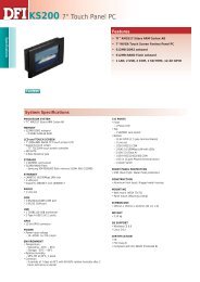


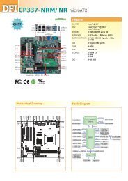
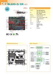
![CP900-B [RoHS] - Dfi](https://img.yumpu.com/18888557/1/184x260/cp900-b-rohs-dfi.jpg?quality=85)
![CP900-B [RoHS] - Dfi](https://img.yumpu.com/18888555/1/184x260/cp900-b-rohs-dfi.jpg?quality=85)
![CP900-B [RoHS] - Dfi](https://img.yumpu.com/18888549/1/184x260/cp900-b-rohs-dfi.jpg?quality=85)
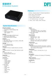
![CP900-B [RoHS] - Dfi](https://img.yumpu.com/18888536/1/184x260/cp900-b-rohs-dfi.jpg?quality=85)