Multi-material Freeform Fabrication of Active Systems - Cornell ...
Multi-material Freeform Fabrication of Active Systems - Cornell ...
Multi-material Freeform Fabrication of Active Systems - Cornell ...

You also want an ePaper? Increase the reach of your titles
YUMPU automatically turns print PDFs into web optimized ePapers that Google loves.
Proceedings <strong>of</strong> the 9th Biennial ASME Conference on Engineering <strong>Systems</strong> Design and Analysis<br />
ESDA08<br />
July 7-9, 2008, Haifa, Israel<br />
MULTI-MATERIAL FREEFORM FABRICATION OF ACTIVE SYSTEMS<br />
Evan Malone<br />
Mechanical & Aerospace Engineering,<br />
<strong>Cornell</strong> University, Ithaca, New York 14853 USA<br />
ABSTRACT<br />
Current Solid <strong>Freeform</strong> <strong>Fabrication</strong> (SFF) technologies can<br />
manufacture, directly from digital data, end-use mechanical<br />
parts in an increasingly wide variety <strong>of</strong> engineering <strong>material</strong>s.<br />
However, commercial SFF systems remain costly, complex,<br />
proprietary, and are limited to working with one or two<br />
proprietary <strong>material</strong>s during the course <strong>of</strong> building a part,<br />
hindering their broader application and the impact <strong>of</strong> the<br />
technology.<br />
The work we present here demonstrates (1) that SFF<br />
systems can employ many <strong>material</strong>s and multiple processes<br />
during the course <strong>of</strong> building a single object, (2) that such<br />
systems can produce complete, active, electromechanical<br />
devices, rather than only mechanical parts, and (3) that such<br />
multi-<strong>material</strong> SFF systems can be made accessible to, and are<br />
<strong>of</strong> interest to the general public. We have developed a researchoriented,<br />
multi-<strong>material</strong> SFF system and employed it to<br />
produce not only mechanical parts, but complete and functional<br />
Zn-air batteries, electrical wiring, flexible circuit boards, straingages,<br />
electromagnets, electroactive polymer actuators,<br />
organic-polymer transistors, and electromechanical relays. We<br />
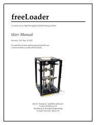
have also developed and published the Fab@Home Model 1<br />
open-source, multi-<strong>material</strong>, freeform fabrication system<br />
design. The Fab@Home project has received broad public and<br />
media attention, and more than 100 Model 1 machines have<br />
been built by individuals around the world.<br />
multi<strong>material</strong>, multi-process, freeform fabrication, additive<br />
manufacturing, rapid prototyping, open-source<br />
1. INTRODUCTION<br />
Solid freeform fabrication (SFF) is the name given to a<br />
class <strong>of</strong> manufacturing methods, sometimes also known as<br />
ESDA2008-59313<br />
Hod Lipson<br />
Mechanical & Aerospace Engineering,<br />
Computing & Information Science<br />
<strong>Cornell</strong> University, Ithaca, New York 14853 USA<br />
Rapid Prototyping (RP), which allow the fabrication <strong>of</strong> threedimensional<br />
structures directly from computer-aided design<br />
(CAD) data. SFF processes are generally additive, in that<br />
<strong>material</strong> is selectively deposited to construct the part, rather<br />
than removed from a block or billet. Most SFF processes are<br />
also layered, meaning that a geometrical description <strong>of</strong> the part<br />
to be produced is cut by a set <strong>of</strong> parallel surfaces (planar or<br />
curved) and the intersections <strong>of</strong> the part and each surface –<br />
referred to as slices or layers – are fabricated sequentially.<br />
Together, these two properties imply that SFF processes are<br />
subject to very different constraints than traditional <strong>material</strong><br />
removal-based manufacturing. As has been demonstrated with<br />
various (but no single) SFF system, nearly arbitrary product<br />
geometries are achievable [1] and parts can be made without<br />
hard tooling, raw <strong>material</strong>s may be more efficiently used than<br />
in subtractive processes, mating parts and fully assembled<br />
mechanisms can be fabricated in a single step [2], exogenously<br />
produced components, such as integrated circuits, can be<br />
“dropped in” during fabrication [3], and multiple <strong>material</strong>s<br />
(including, electronic- [4], chemical-, and bio-<strong>material</strong>s [5-7]<br />
and even living tissues [8, 9]) can be combined to create graded<br />
<strong>material</strong> properties [10-13] and even complete functional<br />
devices [14-16]. Furthermore, one or more SFF processes can<br />
typically be implemented within a single small workcell [3, 14]<br />
– compacting enormously what might have once required many<br />
separate machines.<br />
Given all <strong>of</strong> the above, it would seem possible that with<br />
some combination <strong>of</strong> SFF technologies, one could build a<br />
“compact factory”, or “fabber” capable <strong>of</strong> building almost<br />
anything within a single workcell. Such systems could have<br />
tremendous value as flexible, portable manufacturing facilities<br />
for resource- or time-constrained situations such as catastrophe<br />
response, or polar or space exploration. Furthermore, such<br />
1 Copyright © 2008 by ASME
systems could enable invention, prototyping, and<br />
manufacturing <strong>of</strong> an entirely new space <strong>of</strong> product and device<br />
designs in which geometry and functionality (including active<br />
electromechanical, chemical, and biological functionality) can<br />
be continuously varied and intertwined.<br />
A consumer-oriented fabber, coupled with the networked<br />
educational and technical resources already available today,<br />
could empower individuals with much <strong>of</strong> the innovative facility<br />
that would otherwise require an entire R&D laboratory. This<br />
could potentially lead to economic innovations such as neocottage<br />
industry manufacturing, an “eBay <strong>of</strong> designs” where<br />
individuals can market unique product designs as digital<br />
instructions and <strong>material</strong> recipes for others to execute on their<br />
own fabbers, and millions <strong>of</strong> people inventing technology<br />
rather than merely consuming it.<br />
Despite the aforementioned potential, commercial SFF<br />
technology is still focused on producing passive mechanical<br />
parts in one or two proprietary <strong>material</strong>s, and the emphasis <strong>of</strong><br />
commercial R&D has been on improving the quality,<br />
resolution, and surface finish <strong>of</strong> parts, and on broadening the<br />
range <strong>of</strong> useable <strong>material</strong>s. Growth in the market for and<br />
capability <strong>of</strong> commercial SFF technology has been<br />
disappointingly slow – commercial systems have been<br />
available for more than two decades [17], yet worldwide annual<br />
sales <strong>of</strong> systems are still measured only in thousands [18]. SFF<br />
systems remain very expensive and complex, and are used<br />
primarily by corporate engineers, designers, and architects for<br />
prototyping and visualization and for manufacturing a limited<br />
range <strong>of</strong> end use parts. These factors are linked in a vicious<br />
cycle which slows the development <strong>of</strong> the technology: Niche<br />
applications imply a small demand for machines, restricting<br />
commercial R&D and adoption <strong>of</strong> the new capabilities<br />
demonstrated in the laboratory, while small demand for<br />
machines keeps the machines costly and complex, limiting<br />
them to niche applications.<br />
As will be presented, we are working to free SFF<br />
technology from this trap, and to accelerate the development <strong>of</strong><br />
fabbers by:<br />
1. developing a research SFF system which is<br />
capable <strong>of</strong> employing multiple SFF processes<br />
and many <strong>material</strong>s in the course <strong>of</strong> building a<br />
single object,<br />
2. developing <strong>material</strong>s and designs which allow us<br />
to produce a wide variety <strong>of</strong> functional products<br />
and even complete electromechanical devices<br />
entirely within this single SFF system, and<br />
3. involving the public in developing novel<br />
applications for and innovations in fabbing<br />
technology by designing the Fab@Home Model<br />
1 Personal Desktop Fabricator– an inexpensive<br />
multi-<strong>material</strong> fabber which individuals can<br />
build from a kit, operate, and experiment with,<br />
using free and open-source designs, instructions,<br />
and s<strong>of</strong>tware we provide via a website.<br />
2. RESEARCH SFF SYSTEM<br />
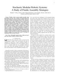
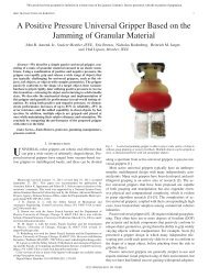
Our multi-<strong>material</strong> freeform fabrication research platform<br />
(Figure 1) consists <strong>of</strong> a 3-axis Cartesian gantry robot, two<br />
changeable <strong>material</strong>-deposition tools, and a s<strong>of</strong>tware<br />
application which processes assemblies <strong>of</strong> STL files into a<br />
multi-<strong>material</strong> manufacturing plan and executes the plan on the<br />
system hardware. Since our first publication on the system [14],<br />
we have reengineered both tools and improved the s<strong>of</strong>tware to<br />
enhance deposition control, speed up changes <strong>of</strong> <strong>material</strong>, and<br />
simplify manufacturing <strong>of</strong> complex multi-<strong>material</strong> objects.<br />
Figure 1. <strong>Multi</strong>-<strong>material</strong> SFF research platform; (a) CAD<br />
rendering <strong>of</strong> the Cartesian gantry positioning system, (b)<br />
photograph <strong>of</strong> actual system with syringe-deposition tool mounted,<br />
(c) components <strong>of</strong> syringe-deposition tool, and (d) components <strong>of</strong><br />
molten-extrusion tool.<br />
The XY-axis gantry moves the mounted tool along planned<br />
deposition paths, while the Z-axis table moves downward to<br />
accommodate deposited <strong>material</strong> layers (Figure 1(a, b)). One<br />
tool (Figure 1(c)) employs syringe-deposition (“robocasting”) to<br />
deposit streams (“roads”) <strong>of</strong> <strong>material</strong> 250-1500µm in diameter,<br />
depending on <strong>material</strong> properties and resolution/fabrication<br />
speed trade<strong>of</strong>f. It is compatible with an enormous range <strong>of</strong><br />
liquid, gel, or paste <strong>material</strong>s, and employs a linear stepper<br />
motor to achieve volumetric dispensing, at up to 1.1MPa<br />
(160PSI). We have redesigned it to dispense from 10mL<br />
disposable syringes mounted in easily changeable cartridges in<br />
order to facilitate rapid <strong>material</strong> changes. The second tool<br />
(Figure 1(d)) employs a molten-extrusion (FDM®) process,<br />
which entails feeding thermoplastic or low-melting point<br />
eutectic alloy feedstock in wire-form into a heated nozzle. This<br />
tool extrudes a fine strand (typically 150-200µm diameter) <strong>of</strong><br />
molten <strong>material</strong> which quickly solidifies, and now has active<br />
feedstock cooling, an optimized pinch roller tooth design, and a<br />
2 Copyright © 2008 by ASME
modular, finger-safe heating block. Tools are mounted to the<br />
XY gantry via a pneumatically-actuated robotic tool changer,<br />
which allows quick and accurate exchanges <strong>of</strong> tools.<br />
We have created a custom computer-aided manufacturing<br />
(CAM) application which imports individual or assemblies <strong>of</strong><br />
tessellated geometry (polyhedra) as STL files, generates<br />
hardware executable manufacturing plans, and controls their<br />
execution on the fabrication hardware. The system operator<br />
uses a graphical interface (GUI) to specify with which<br />
<strong>material</strong>/tool combination each polyhedron should be<br />
fabricated. The toolpath planning consists <strong>of</strong> slicing each<br />
polyhedron according to the road thickness associated with its<br />
particular <strong>material</strong>/tool combination, <strong>of</strong>fsetting resulting<br />
boundary polygons by ½ <strong>of</strong> the road width for the <strong>material</strong>/tool,<br />
and filling enclosed areas with raster (hatch) paths. Slices<br />
(containing paths) are then sorted by their height and executed,<br />
with the s<strong>of</strong>tware prompting the operator to change the <strong>material</strong><br />
and/or tool as required. Our hardware currently allows only one<br />
tool/<strong>material</strong> combination to be mounted at a time, and changes<br />
are manually executed, so time and labor become a significant<br />
factor for complex products, such as batteries.<br />
To reduce the cost associated with tool/<strong>material</strong> switching,<br />
we have developed a fabrication process extension, dubbed<br />
“Backfill Deposition”, which allows overriding the layer<br />
height-ordering <strong>of</strong> the process plan to fabricate some parts <strong>of</strong><br />
the structure before others. In practice, as geometry data<br />
describing component parts <strong>of</strong> a product such as a battery are<br />
imported into the fabrication system s<strong>of</strong>tware, the operator may<br />
use the GUI to assign a sequential “fabrication priority” to each<br />
<strong>of</strong> the parts. Our SFF system will fabricate higher priority parts<br />
<strong>of</strong> an assembly to their full height prior to fabricating lower<br />
priority parts, in contrast to strict layered fabrication. This can<br />
reduce the number <strong>of</strong> tool changes in some cases from one per<br />
layer, down to one per STL file (or part). Additionally, this<br />
option facilitates fabrication <strong>of</strong> products which contain or are<br />
made from liquid <strong>material</strong>s – it allows the fabrication system to<br />
construct a container before filling it.<br />
3. FUNCTIONAL PRODUCTS AND DEVICES<br />
In order to prove the principle that multi-process, multi<strong>material</strong><br />
SFF systems can begin to approximate the capabilities<br />
that we have envisioned for future fabbers, we have used our<br />
SFF systems to produce a wide variety <strong>of</strong> functional products<br />
and electromechanical devices, with the eventual goal <strong>of</strong> being<br />
able to freeform fabricate an entire mobile robot as a capstone<br />
demonstration. Each <strong>of</strong> these products required a significant<br />
R&D effort which included developing or adapting product<br />
designs for compatibility with SFF manufacturing, and<br />
formulating functional raw <strong>material</strong>s which are compatible with<br />
SFF processes without sacrificing their essential functionality.<br />
The key observation from the sum <strong>of</strong> these efforts is that once<br />
the designs and <strong>material</strong>s have been proven successful, a single<br />
SFF system can produce any <strong>of</strong> these objects, and we intend to<br />
show in future work, can produce many <strong>of</strong> them integrated into<br />
a single multifunctional product.<br />
3.1. Batteries<br />
In prior work [14], we demonstrated the first freeform<br />
fabrication <strong>of</strong> complete, macroscopic Zn-air batteries – a<br />
milestone in SFF not only for being a functional battery, but<br />
also for the number <strong>of</strong> separate <strong>material</strong>s (five) involved. We<br />
have continued to refine the <strong>material</strong>s and techniques,<br />
including backfill deposition, required to produce Zn-air<br />
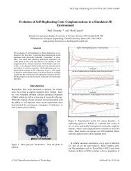
batteries, and have since achieved cylindrical batteries (Figure<br />
3(a)) with energy density and power density about 10% that <strong>of</strong><br />
commercial, mass-produced batteries (Figure 2) [19].<br />
100<br />
10<br />
1<br />
0.1<br />
0.01<br />
0.001<br />
0.0001<br />
Calculated Structural and Measured Performance Metrics for Commercial Button and SFF Cylindrical<br />
Zn-Air Batteries<br />
Continuous Discharge to 0.25V, 100Ohm Load<br />
Zn Anode Bulk Zn Density (%)<br />
Renata ZA5,<br />
N=8<br />
Renata ZA10,<br />
N=4<br />
Renata ZA675,<br />
N=4<br />
SFF Half, N=1 SFF Basic, N=4 SFF Triple, N=1<br />
Average Current Density - Cell<br />
Basis (mA/cm2)<br />
Zn Utilization (% Theoretical)<br />
Average Power Area Density - Cell<br />
Basis (mW/cm2)<br />
Internal Conductivity (Mho/cm2)<br />
Figure 2. Structure and performance comparison between several<br />
sizes <strong>of</strong> commercially manufactured Zn-air batteries and solid<br />
freeform fabricated (SFF) Zn-air batteries. Error bars are<br />
provided for cases in which multiple batteries were tested - N<br />
indicates the sample size.<br />
We have also demonstrated, by producing a flexible, “U”<br />
shaped Zn-air battery containing 2 cells (Figure 3(b)), that via<br />
SFF we can geometrically and functionally customize batteries.<br />
(a) (b)<br />
Figure 3. Functional Zn-air batteries produced entirely by SFF:<br />
(a) a cylindrical battery containing one cell; (b) a flexible, "U"<br />
shaped battery containing 2 cells.<br />
We believe that SFF allows design freedom and packaging<br />
density superior to what can be achieved with packs <strong>of</strong> mass<br />
produced batteries, and thus expect SFF to become a<br />
competitive technique for custom batteries if we can achieve<br />
performance within about 20% that <strong>of</strong> mass-produced batteries.<br />
We have identified likely performance bottlenecks, and are<br />
actively seeking solutions for them.<br />
3 Copyright © 2008 by ASME
3.2. Wiring, Circuit Boards, Strain Gages, &<br />
Electromagnets<br />
An essential functionality for any electromechanical device<br />
is electrical circuitry – wiring. We have developed two<br />
approaches to freeform fabrication <strong>of</strong> wiring, based on two<br />
types <strong>of</strong> <strong>material</strong>s, each with particular benefits and drawbacks.<br />
The first class <strong>of</strong> <strong>material</strong>s could be described as<br />
conductive composites, e.g. polymers filled with a granular<br />
conductive phase. These include commercially available silver<br />
inks, our own ink formulations, and silver-filled silicone<br />
rubber. These <strong>material</strong>s have the benefit <strong>of</strong> simple, roomtemperature<br />
processing, and are typically flexible, or even<br />
elastic, but the drawback <strong>of</strong> having relatively high resistivity –<br />
typically ~ 10 -3 Ω-cm. Their “s<strong>of</strong>t” nature immediately<br />
suggests novel applications beyond simple wiring. Figure 4<br />
shows a freeform fabricated functional, flexible printed circuit<br />
board comprising Ag-filled silicone traces embedded in<br />
insulating silicone. Figure 5 shows how with a simple change <strong>of</strong><br />
the CAD model sent to the SFF system, the same combination<br />
<strong>of</strong> <strong>material</strong>s can be configured as a functional strain gage.<br />
(a) (b)<br />
Figure 4. A two-dimensional flexible printed circuit: (a) as fabbed<br />
(dimensions in centimeters); (b) with components inserted and<br />
power supplied.<br />
(a) (b)<br />
Figure 5. (a) A silver-filled silicone strain gage (dimensions in<br />
mm); (b) resistance vs. strain data over 100 cycles.<br />
The second class <strong>of</strong> <strong>material</strong>s is fusible metals which have<br />
low melting points, such as alloys <strong>of</strong> Pb, Sn, Bi, Sb, or In.<br />
These <strong>material</strong>s <strong>of</strong> course require elevated-temperature<br />
processing, but have the benefit <strong>of</strong> very high conductivity –<br />
typically ~ 10 -5 Ω-cm. By careful tuning <strong>of</strong> deposition<br />
parameters, we have achieved continuous deposition <strong>of</strong> Sn-Sb<br />
alloy strands 0.5mm in diameter and more than 5m long. This<br />
combination <strong>of</strong> high conductivity and fine gage has enabled us<br />
to freeform fabricate coils <strong>of</strong> sufficient density and number <strong>of</strong><br />
turns to produce functional electromagnets (Figure 6). Our best<br />
result so far has been three consecutive stacked layers <strong>of</strong> 20<br />
turns each at about 1 turn/mm <strong>of</strong> radius. To amplify the<br />
magnetic field, we have employed a core <strong>material</strong> consisting <strong>of</strong><br />
80wt% iron filings in lithium grease, which is readily deposited<br />
via the syringe deposition tool.<br />
(a) (b)<br />
Figure 6. <strong>Freeform</strong> fabrication <strong>of</strong> an electromagnet: (a) depositing<br />
multiple layers <strong>of</strong> Sb-Sn alloy wire coils atop a freeform fabricated<br />
silicone base via the molten-extrusion tool; (b) a complete<br />
electromagnet assembly.<br />
3.3. Electroactive Polymer Actuators<br />
Rotary electromagnetic motors are the dominant form <strong>of</strong><br />
electromechanical actuator in the world today. Despite our<br />
success with electromagnets, which are a key subsystem <strong>of</strong><br />
rotary motors, freeform fabrication <strong>of</strong> a complete rotary<br />
electromagnetic motor remains a “grand challenge” for SFF<br />
due to the complexity <strong>of</strong> moving coils, bearings, etc.<br />
Fortunately, electromechanically active <strong>material</strong>s exist which<br />
can be configured as mechanical actuators in a relatively simple<br />
fashion. We have investigated a particular type <strong>of</strong> device,<br />
known as an Ionomeric Polymer-Metal Composite (IPMC)<br />
Actuator, which typically comprises two or three <strong>material</strong>s, and<br />
which bends in response to a low voltage electrical signal. We<br />
adapted the IPMC solution-processing research <strong>of</strong> Kim and<br />
Shahinpoor [20] by formulating <strong>material</strong>s compatible with SFF<br />
processes, and developed the technique <strong>of</strong> fabricating the<br />
container for the actuator <strong>material</strong>s along with the actuator – a<br />
key innovation which enables actuators to be embedded within<br />
more complicated freeform fabricated devices. Using these<br />
innovations, we have successfully demonstrated freeform<br />
fabrication <strong>of</strong> complete IPMC actuators, and documented the<br />
longest reported operating life in air for IPMCs manufactured<br />
by any method [21]. As with batteries, however, freeform<br />
fabricated IPMCs have inferior performance in several metrics<br />
– blocked stress, bandwidth, and range <strong>of</strong> motion – to those<br />
produced by established laboratory methods. We are continuing<br />
4 Copyright © 2008 by ASME
to refine the <strong>material</strong>s and the control <strong>of</strong> their deposition with<br />
the goal <strong>of</strong> closing the performance gap and allowing greater<br />
freedom in the shape and orientation <strong>of</strong> freeform fabricated<br />
IPMCs.<br />
3.4. Organic Polymer Transistors<br />
Solution-processable organic semiconductor <strong>material</strong>s can<br />
be used to print transistors under ambient conditions which are<br />
robust enough to function on flexible substrates, and are useful<br />
for inexpensive, disposable, and/or flexible applications.<br />
Specifically, organic electrochemical transistors (ECT)<br />
function at low voltages and with large feature sizes, making<br />
them good candidates for freeform fabricated devices. In prior<br />
work, we have reported the first functional ECTs produced via<br />
freeform fabrication on glass substrates [22].<br />
(a) (b)<br />
Figure 7. (a) A 3D CAD model <strong>of</strong> a printable transistor. The<br />
yellow <strong>material</strong> indicates silicone boundaries, while the dark blue<br />
<strong>material</strong> is PEDOT:PSS. The liquid electrolyte is held within the<br />
partially transparent boundary. (b) A completed transistor set up<br />
for characterization (the grid size is 1cm).<br />
Our freeform fabricated transistors (Figure 7) are made by<br />
depositing boundary patterns <strong>of</strong> silicone on a glass substrate,<br />
via the syringe deposition tool, to define the source and drain<br />
regions.<br />
Drain Current (uA)<br />
0<br />
-0.35<br />
-0.3<br />
-0.25<br />
-0.2<br />
-0.15<br />
-0.1<br />
-0.05<br />
0<br />
0.05<br />
-0.1<br />
-0.2<br />
-0.3<br />
Drain Voltage (V)<br />
-0.4<br />
-0.5<br />
-0.6<br />
Vg = 0.2 V<br />
Vg = 0.2 V<br />
Vg = 0.1 V<br />
Vg = 0.0 V<br />
Figure 8. Drain current vs. drain voltage curves for a single<br />
printed transistor for various gate voltages. The transistor was<br />
measured twice at 0.2V applied to the gate, then once at 0.1V, and<br />
once at 0V.<br />
The same tool is then used to deposit our preferred organic<br />
semiconductor, PEDOT:PSS dispersed in water, into the source<br />
and drain boundaries. A silicone boundary to define the gate<br />
region is then deposited and filled with CaCl2 electrolyte.<br />
Silver-ink contact pads are hand-painted and devices are<br />
connected to a data acquisition system for testing.<br />
Our freeform devices show stable operation in air over at<br />
least one hour and several measurement cycles, have a sourcedrain<br />
current <strong>of</strong> 0.1μA at -0.5Vsd, which is an order <strong>of</strong><br />
magnitude larger than the gate (leakage) current, and an on/<strong>of</strong>f<br />
ratio <strong>of</strong> 2 at 0.2Vgate (Figure 8). These preliminary devices<br />
have source-drain current three orders <strong>of</strong> magnitude lower than<br />
literature values for similar ECTs. This work has enabled us to<br />
study ECT behavior on printable substrates, necessary to<br />
ultimately incorporating ECTs into fully integrated freeform<br />
fabricated electromechanical devices.<br />
3.5. Electromechanical Relays<br />
We have investigated producing electromechanical relays<br />
entirely via freeform fabrication as part <strong>of</strong> our larger effort to<br />
freeform fabricate complete electromechanical devices. Relays<br />
which can switch using an input current <strong>of</strong> less than 100<br />
microamperes, current gain greater than 10, and an open/closed<br />
resistance ratio <strong>of</strong> greater than 10 3 will make feasible the<br />
control <strong>of</strong> freeform fabricated actuators by printable organic<br />
polymer transistor circuits, opening up a design space <strong>of</strong><br />
completely freeform fabricated electromechanical actuation<br />
systems. Relays have been produced before in part through SFF<br />
processes [16], but that work involved metal machining<br />
processes as well as assembly <strong>of</strong> parts. We need to produce<br />
such a device entirely via SFF processes that are compatible<br />
with all <strong>of</strong> the other freeform fabricated devices we can<br />
produce, so that a single compact fabrication system can build<br />
up complete electromechanical devices without any assembly<br />
<strong>of</strong> parts.<br />
IPMC “Armature”<br />
Figure 9. Schematic <strong>of</strong> an IPMC-based electromechanical relay<br />
We conceived a simple relay design (Figure 9) which makes<br />
use <strong>of</strong> our prior successes in freeform fabrication <strong>of</strong> ionomeric<br />
polymer-metal composite actuators (IPMC). The electrically<br />
conductive surface electrodes <strong>of</strong> an IPMC serve to selectively<br />
close or open a load circuit as the actuator deforms, and the<br />
mold used for casting the actuator <strong>material</strong>s also serves as the<br />
relay housing. We have explored candidate switch contact<br />
<strong>material</strong>s, IPMC electroding <strong>material</strong>s, candidate housing and<br />
contact designs, and manufacturing sequences to find<br />
5 Copyright © 2008 by ASME
combinations which result in functional IPMCs which when<br />
hydrated release themselves from the load contacts while<br />
maintaining signal contact, yet have low contact resistance with<br />
the load contacts. Thus far, we have freeform fabricated test<br />
housings, and then manually cast variants <strong>of</strong> IPMC <strong>material</strong>s<br />
into these housings, and tested these partially freeform<br />
fabricated relays using a PC-based data acquisition system.<br />
Given our success with complete freeform fabrication <strong>of</strong> IPMC<br />
actuators, this manual casting for expediency during testing<br />
should not be considered evidence <strong>of</strong> any additional difficulty<br />
in automating the casting for this application.<br />
Current [A]<br />
0.02<br />
0.01<br />
0<br />
-0.01<br />
Stimulus Current vs. Time<br />
-0.02<br />
0 50 100<br />
Elapsed Time [s]<br />
Load Path Resistance vs. Time<br />
150 200<br />
Load Path Resistance [Ohm]<br />
10 3<br />
10<br />
0 50 100 150 200<br />
2<br />
Elapsed Time [s]<br />
Figure 10. Successful test <strong>of</strong> partially freeform fabricated relay;<br />
IMPC input signal 1.2V, 0.05Hz square wave, V Load = 1.2VDC<br />
These partially freeform-fabricated relays achieved a<br />
controllable load path resistance change <strong>of</strong> a factor <strong>of</strong> two at<br />
switching frequencies up to 0.05 Hz with a 1.2V control input<br />
and an RMS input current <strong>of</strong> 3.8mA (Figure 10). At 1.2V load<br />
potential, load/input current gain is roughly 1.05. The device<br />
functions above 1Hz, but current gain falls below 1.<br />
4. THE FAB@HOME PROJECT<br />
Future fabricator systems that can produce complex functional<br />
artifacts comprising many <strong>material</strong>s will transform the way we<br />
design, make, deliver and consume some products, and enable<br />
the creation <strong>of</strong> entirely new products that will be literally<br />
impossible to produce otherwise.<br />
Unfortunately, the key to these future fabbers, SFF<br />
technology, is trapped in a “chicken and egg” paradox, in<br />
which having only niche applications keeps SFF technology<br />
expensive and little known, and being expensive and little<br />
known, few new applications for SFF systems are developed,<br />
and the demand for SFF systems is too small to reduce their<br />
cost.<br />
In order to escape this paradox, and to accelerate the spread<br />
and development <strong>of</strong> personal fabrication technology, we have<br />
developed the Fab@Home Project, and an open-source, lowcost,<br />
personal fabricator system kit, which we call the<br />
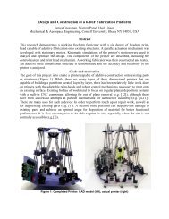
“Fab@Home Model 1” (Figure 11(a)). Our project has been<br />
inspired by the open-source approach employed by Bowyer’s<br />
RepRap Project [23] toward the goal <strong>of</strong> developing selfreplicating<br />
fabbers. The aim <strong>of</strong> our project is to put SFF<br />
technology into the hands <strong>of</strong> the maximum number <strong>of</strong> curious,<br />
inventive, and entrepreneurial individuals, and to help them to<br />
drive the expansion and advancement <strong>of</strong> the technology.<br />
18.5”<br />
(47 cm)<br />
16”<br />
(41cm)<br />
18”<br />
(46cm)<br />
(a) (b)<br />
Figure 11. The Fab@Home Model 1 Design. (a) 3D CAD model <strong>of</strong><br />
an assembled Model 1; (b) An example <strong>of</strong> assembly instructions<br />
available via the project website<br />
The Model 1 kit has a parts cost <strong>of</strong> roughly $2300, includes<br />
a free, open-source application to control the fabber, requires<br />
only basic hobbyist tools and skills to assembly and use, and<br />
can be used to deposit almost any room-temperature liquid or<br />
paste. It is essentially a simplified version <strong>of</strong> our research<br />
platform, but uses only a syringe deposition tool, and is slower<br />
and has lower resolution. We have used Model 1 machines to<br />
make multi<strong>material</strong> objects, and it could certainly be used to<br />
make most <strong>of</strong> the functional devices that we have produced<br />
with our research platform.<br />
We have endeavored to make obtaining, assembling, using,<br />
and experimenting with the Model 1 as simple and intuitive as<br />
possible – the website provides step-by-step ordering, assembly<br />
(Figure 11(b)) and operational instructions, and the application<br />
has an animated graphical user interface (Figure 12).<br />
Figure 12. A screenshot from the PC application displaying a<br />
model ready for fabrication and dialog boxes for positioning and<br />
real-time status information<br />
To promote collaborative development <strong>of</strong> the technology,<br />
we have developed a user-editable “wiki” website [24] to<br />
6 Copyright © 2008 by ASME
publish the designs and documentation, have set up discussion<br />
forums using a free online service, and have shared the source<br />
code for the project via a free service which facilitates opensource<br />
s<strong>of</strong>tware development. Through these media,<br />
participants in Fab@Home have begun to exchange their ideas<br />
for applications and their improvements to the hardware and<br />
s<strong>of</strong>tware with us and each other. Kits and fully assembled<br />
machines can be purchased from two vendors in the United<br />
States [25, 26], and to date, approximately 100 Model 1<br />
systems have been purchased or assembled worldwide. The<br />
Science Museum <strong>of</strong> London, UK, has added a Model 1 to their<br />
permanent collection and displayed it in an exhibition on the<br />
history <strong>of</strong> plastics (Figure 13(a))[27].<br />
(a) (b)<br />
Figure 13. (a) A Model 1 on display in the Science Museum,<br />
London; (b) a Model 1 built by students <strong>of</strong> Pr<strong>of</strong>. Mark Ganter at<br />
the University <strong>of</strong> Washington for use in a course on Computer<br />
Aided Technology.<br />
At the University <strong>of</strong> Washington, students <strong>of</strong> Pr<strong>of</strong>. Mark<br />
Ganter have constructed two Model 1 (Figure 13(b)),<br />
Fab@Home machines for use in a course on Computer-Aided<br />
Technology [28]. A number <strong>of</strong> machines have been assembled<br />
at universities worldwide for a variety <strong>of</strong> student and faculty<br />
research projects [29].<br />
As shown in Figure 14, a variety <strong>of</strong> <strong>material</strong>s can be used<br />
with the Model 1, to create tall (800 layers, ~11.5cm tall),<br />
functional, and multi-<strong>material</strong> objects, including fabbed objects<br />
with conventionally manufactured parts embedded.<br />
In the 15 months since October 2006 (when the website was<br />
first made publicly accessible), the project website has had<br />
more than 9.8 million requests for pages from more than<br />
480,000 distinct visitors in more than 150 countries [30].<br />
Users have begun to make contributions to the Fab@Home<br />
wiki, the Google Group, and the SourceForge project in the<br />
form <strong>of</strong> new deposition process ideas, bug reports, questions,<br />
feature requests, alternative vendors, group purchasing<br />
arrangements, and more.<br />
The growth <strong>of</strong> the Fab@Home Project has been accelerated<br />
enormously by media coverage and an award. Newsweek<br />
International [31], Newsweek Russia [32], Popular Mechanics<br />
[33], Popular Science [34], The Guardian [35], and The New<br />
York Times [36] have published brief articles or mention <strong>of</strong><br />
Fab@Home, and Discovery Channel Canada’s DailyPlanet<br />
science news show [37] and the Wall Street Journal Online [38]<br />
have covered the project in video format. Popular Mechanics<br />
magazine awarded Fab@Home a “Breakthrough Award” for<br />
innovation in 2007 [39]. Each instance <strong>of</strong> media coverage<br />
results in a large surge <strong>of</strong> visits to our website, and many<br />
inquiries about the capabilities <strong>of</strong> the Model 1, and many new<br />
orders for Model 1 kits.<br />
(a) (b)<br />
(c) (d)<br />
Figure 14. Objects built with a Fab@Home Model 1: (a) A<br />
working flashlight – only the LED and batteries are not printed;<br />
(b) an epoxy propeller for a model airplane; (c) a personalized<br />
chocolate bar; (d) a silicone toy with fabbed embedded circuitry<br />
which allows the LED eyes to light when the chest is squeezed<br />
We are continuing development <strong>of</strong> the s<strong>of</strong>tware and<br />
hardware <strong>of</strong> the Model 1 to provide performance and usability<br />
enhancements in anticipation <strong>of</strong> an onslaught <strong>of</strong> questions and<br />
complaints as the first wave <strong>of</strong> Model 1 users finish assembling<br />
and start using their machines. This will be a critical test <strong>of</strong> the<br />
survival <strong>of</strong> Fab@Home, and we must ensure that we do not<br />
discourage these brave early adopters.<br />
5. CONCLUSIONS<br />
Manufacturing automation increases the power <strong>of</strong> humans to<br />
shape matter into complicated and useful forms, allowing ideas<br />
expressed in design s<strong>of</strong>tware on a computer to be physically<br />
realized with little or no human contact with the raw <strong>material</strong>s.<br />
The compact factories, or “fabbers”, we describe here have the<br />
potential to greatly increase this power, by compressing much<br />
<strong>of</strong> the technological manufacturing capacity <strong>of</strong> our civilization<br />
into a tool which can be wielded by a single individual.<br />
Solid freeform fabrication technology is currently the most<br />
promising approach to realizing fabbers. We believe that the<br />
advancement <strong>of</strong> fabbing technology is being constrained by the<br />
high cost and proprietary nature <strong>of</strong> commercially available SFF<br />
systems. High costs limit experimentation and market scale,<br />
which in turn limit the development <strong>of</strong> new applications which<br />
would increase demand and reduce system and product prices.<br />
We have been attacking this problem in two ways: by<br />
demonstrating that SFF is not just for mechanical parts<br />
anymore – it is capable <strong>of</strong> producing complete devices with<br />
7 Copyright © 2008 by ASME
combined mechanical, electrical, biological, and presumably<br />
even other functionalities, and by involving the general public<br />
in the development <strong>of</strong> fabbing technology, via the Fab@Home<br />
open-source, personal desktop fabricator kit. Our future work<br />
will continue to include the promotion <strong>of</strong> fabbing technology<br />
through the Fab@Home project in the hope <strong>of</strong> expanding<br />
public interest, decreasing the cost <strong>of</strong> fabber systems, and<br />
driving innovation in fabbing.<br />
6. ACKNOWLEDGMENTS<br />
This work was supported in parts by the NSF, grant number<br />
DMI 0547376, and in parts by the Learning Initiatives for<br />
Future Engineers student research grant program at <strong>Cornell</strong><br />
University. Thanks to Megan Berry, Robin Havener, John<br />
Boyea, Matthew Alonso, and especially Dan Periard for their<br />
contributions to this work.<br />
7. REFERENCES<br />
[1] Sequin, C.H., Rapid prototyping: a 3D visualization<br />
tool takes on sculpture and mathematical forms.<br />
Communications <strong>of</strong> the ACM, 2005. 48(6): p. 66.<br />
[2] De Laurentis, K.J., F.F. Kong, and C. Mavroidis.<br />
Procedure for rapid fabrication <strong>of</strong> non-assembly<br />
mechanisms with embedded components. 2002.<br />
Montreal, Que., Canada: American Society <strong>of</strong><br />
Mechanical Engineers.<br />
[3] Weiss, L.E., et al., Shape deposition manufacturing <strong>of</strong><br />
heterogeneous structures. Journal <strong>of</strong> Manufacturing<br />
<strong>Systems</strong>, 1997. 16(4): p. 239-249.<br />
[4] Clemens, W., et al., From polymer transistors toward<br />
printed electronics. Journal <strong>of</strong> Materials Research,<br />
2004. 19(7): p. 1963.<br />
[5] Khalil, S., J. Nam, and W. Sun, <strong>Multi</strong>-nozzle<br />
deposition for construction <strong>of</strong> 3D biopolymer tissue<br />
scaffolds. Rapid Prototyping Journal, 2005. 11(1): p.<br />
9-17.<br />
[6] Geng, L., et al., Direct writing <strong>of</strong> chitosan scaffolds<br />
using a robotic system. Rapid Prototyping Journal,<br />
2005. 11(2): p. 90-97.<br />
[7] Sachlos, E. and J.T. Czernuszka, Making tissue<br />
engineering scaffolds work: Review on the application<br />
<strong>of</strong> solid freeform fabrication technology to the<br />
production <strong>of</strong> tissue engineering scaffolds. European<br />
Cells & Materials, 2003. 5(January-June Cited July<br />
25, 2003): p. 29-40.<br />
[8] Mironov, V.B., Thomas; Trusk, Thomas; Forgacs,<br />
Gabor; Markwald, Roger R. , Organ printing:<br />
Computer-aided jet-based 3D tissue engineering.<br />
Trends in Biotechnology, 2003. 21(4): p. 157-161.<br />
[9] Cohen, D.L., et al., Direct freeform fabrication <strong>of</strong><br />
seeded hydrogels in arbitrary geometries. Tissue<br />
Engineering, 2006. 12(5): p. 1325.<br />
[10] Ouyang, J.H., H. Mei, and R. Kovacevic. Rapid<br />
prototyping and characterization <strong>of</strong> a WC-(NiSiB<br />
alloy) ceramet/tool steel functionally graded <strong>material</strong><br />
(FGM) synthesized by laser cladding. 2002.<br />
Columbus, OH, USA: TMS - Miner. Metals & Mater.<br />
Soc.<br />
[11] Smurov, I.Y. and A. Yakovlev, Laser-assisted direct<br />
manufacturing <strong>of</strong> functionally graded 3D objects by<br />
coaxial powder injection. Proceedings <strong>of</strong> the SPIE -<br />
The International Society for Optical Engineering,<br />
2004. 5399(1): p. 27.<br />
[12] Noecker, F.F., II and J.N. DuPont. Functionally<br />
graded copper-steel using LENS process. 2002.<br />
Columbus, OH, USA: TMS - Miner. Metals & Mater.<br />
Soc.<br />
[13] Domack, M.S. and J.M. Baughman, Development <strong>of</strong><br />
nickel-titanium graded composition components.<br />
Rapid Prototyping Journal, 2005. 11(1): p. 41.<br />
[14] Malone, E., et al., <strong>Freeform</strong> fabrication <strong>of</strong> zinc-air<br />
batteries and electromechanical assemblies. Rapid<br />
Prototyping Journal, 2004. 10(1): p. 58-69.<br />
[15] Malone, E. and H. Lipson, <strong>Freeform</strong> fabrication <strong>of</strong><br />
ionomeric polymer-metal composite actuators. Rapid<br />
Prototyping Journal, 2006. 12(5): p. 244.<br />
[16] Palmer, J.A., et al., Mesoscale RF relay enabled by<br />
integrated rapid manufacturing. Rapid Prototyping<br />
Journal, 2006. 12(3): p. 148.<br />
[17] Prinz, F.B., et al., JTEC/WTEC Panel Report on Rapid<br />
Prototyping in Europe and Japan VOLUME I.<br />
ANALYTICAL CHAPTERS. 1997, Japanese<br />
Technology Evaluation Center/World Technology<br />
Evaluation Center. p. Ch. 3.<br />
[18] Wohlers, T., Wohlers Report 2006. 2006, Wohlers<br />
Associates: Fort Collins. p. 250.<br />
[19] Malone, E., M. Berry, and H. Lipson, <strong>Freeform</strong><br />
<strong>Fabrication</strong> and Characterization <strong>of</strong> Zn-Air Batteries.<br />
Rapid Prototyping Journal, 2008. Accepted.<br />
[20] Kim, K.J. and M. Shahinpoor, A novel method <strong>of</strong><br />
manufacturing three-dimensional ionic polymer-metal<br />
composites (IPMCs) biomimetic sensors, actuators<br />
and artificial muscles. Polymer, 2002. 43(3): p. 797-<br />
802.<br />
[21] Malone, E. and H. Lipson, <strong>Freeform</strong> <strong>Fabrication</strong> <strong>of</strong><br />
Ionomeric Polymer-Metal Composite Actuators. Rapid<br />
Prototyping Journal, 2006. 12(5): p. 244-253.<br />
[22] Havener, R., et al. <strong>Freeform</strong> <strong>Fabrication</strong> <strong>of</strong> Organic<br />
Electrochemical Transistors. in Solid <strong>Freeform</strong><br />
<strong>Fabrication</strong> Symposium, Proceedings <strong>of</strong> the 18th.<br />
2007. Austin, TX, USA.<br />
[23] Bowyer, A. RepRap. 1999 [cited 1/21/2006];<br />
Available from: http://www.reprap.org.<br />
[24] Malone, E., et al. Fab@Home.org. [website] 2006<br />
[cited 2007 3/31/2007]; Available from:<br />
http://www.fabathome.org.<br />
8 Copyright © 2008 by ASME
[25] Ball, C. Koba Industries Fab@Home Kits. [Website]<br />
2007 [cited 2007 3/31/2007]; Available from:<br />
http://www.kobask8.com/servlet/Categories?category<br />
=Fab%40Home.<br />
[26] Automated Creation Technologies. ACT Products.<br />
[Web Page] 2008 [cited 2008 January 26]; Available<br />
from: http://acreationtech.com/products.htm.<br />
[27] Science Musuem London. Plasticity - 100 years <strong>of</strong><br />
making plastics. [Website] 2007 April 4, 2007 [cited<br />
2007 April 26]; Available from:<br />
http://www.sciencemuseum.org.uk/about_us/press_an<br />
d_media/press_releases/2007/04/468.aspx?keywords=<br />
plastics.<br />
[28] Ganter, M. ME 480 Introduction to Computer-Aided<br />
Technology. 2007 April 26, 2007 [cited 2007 April<br />
26]; Available from:<br />
http://www.washington.edu/students/crscat/meche.htm<br />
l#me480.<br />
[29] Contributors. Fab@Home: Fabbers <strong>of</strong> the World.<br />
[Web Page] 2008 [cited 2008 January 26]; Available<br />
from:<br />
http://www.fabathome.org/wiki/index.php?title=Fab%<br />
40Home:Fabbers_<strong>of</strong>_the_World.<br />
[30] Malone, E., et al. Web Statistics for Fab@Home.<br />
[website] 2007 [cited 2007 3/31/2007]; Available<br />
from:<br />
http://www.fabathome.org/wiki/FAHServerStats/index<br />
.html.<br />
[31] Falby, P., Computers: Factory in a Kit, in Newsweek,<br />
International Edition. 2007.<br />
[32] Rotkin, A., Славомир Грунберг, Александр Роткин<br />
Мастер на все рюмки in Newsweek Russia. 2007.<br />
[33] Hutchinson, A., The Printed World, in Popular<br />
Mechanics. 2007. p. 18.<br />
[34] Binns, C., The Desktop Factory, in Popular Science.<br />
2007, Bonnier: New York. p. 42-44.<br />
[35] Pollitt, M., The 'fab' machine that could spark an<br />
industrial revolution, in The Guardian. 2007: London,<br />
UK. p. 6.<br />
[36] Wayner, P., Beaming Up 3-D Objects on a Budget, in<br />
The New York Times. 2007: New York City.<br />
[37] Belanger, L., Fab@Home, in Daily Planet, J.<br />
Morrison, Editor. 2007, Discovery Channel, Canada:<br />
Toronto.<br />
[38] Jordan, A. Printing in 3D. [Video] 2007 [cited 2008<br />
January 26]; Available from:<br />
http://online.wsj.com/public/page/8_0006.html?bcpid<br />
=86195573&bclid=86272812&bctid=1328213802.<br />
[39] Ward, L., BREAKTHROUGH AWARDS: THINKING<br />
BIG. Popular Mechanics, 2007. 184(11): p. 72-82.<br />
9 Copyright © 2008 by ASME