R&D Proposal - Solid State Detectors Support and R&D - CERN
R&D Proposal - Solid State Detectors Support and R&D - CERN
R&D Proposal - Solid State Detectors Support and R&D - CERN

You also want an ePaper? Increase the reach of your titles
YUMPU automatically turns print PDFs into web optimized ePapers that Google loves.
1<br />
2<br />
3<br />
4<br />
5<br />
6<br />
7<br />
8<br />
9<br />
10<br />
11<br />
12<br />
13<br />
14<br />
15<br />
16<br />
17<br />
18<br />
19<br />
20<br />
21<br />
22<br />
23<br />
24<br />
25<br />
26<br />
27<br />
28<br />
29<br />
30<br />
31<br />
32<br />
33<br />
34<br />
35<br />
36<br />
37<br />
38<br />
39<br />
40<br />
41<br />
Draft of LHCC 2002-003 / P6 Version 2.3 - 8. February 2002 – 1/36<br />
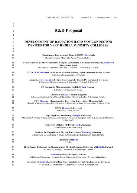
R&D <strong>Proposal</strong><br />
DEVELOPMENT OF RADIATION HARD SEMICONDUCTOR<br />
DEVICES FOR VERY HIGH LUMINOSITY COLLIDERS<br />
Dipartimento Interateneo di Fisica & INFN - Bari, Italy<br />
Donato Creanza, Mauro De Palma, Valeria Radicci<br />
Centro Nacional de Microelectrónica, Campus Universidad Autónoma de Barcelona, Bellaterra<br />
(Barcelona), Spain<br />
M.Lozano, F.Campabadal, M.Ullán, C.Martínez, C.Fleta, M.Key, J.M.Rafí<br />
NCSR DEMOKRITOS, Institute of Materials Science, Aghia Paraskevi Attikis, Greece<br />
G.Kordas, A.Kontogeorgakos, C.Trapalis<br />
Universitaet Dortmund, Lehrstuhl Experimentelle Physik IV, Dortmund, Germany<br />
C.Goessling, J.Klaiber-Lodewigs, R.Klingenberg, O.Krasel, R.Wunstorf<br />
CiS Institut für Mikrosensorik gGmbH, Erfurt, Germany<br />
R.Röder, H. Übensee, D. Stolze<br />
University of Exeter, United Kingdom<br />
R.Jones, J.Coutinho, C.Fall, J.Goss, B.Hourahine, T.Eberlein, J.Adey, A.Blumenau, N.Pinho<br />
INFN Florence – Department of Energetics, University of Florence, Italy<br />
E.Borchi, M.Bruzzi, M.Bucciolini, S.Sciortino, D.Menichelli, A.Baldi, S.Lagomarsino, S.Miglio, S.Pini<br />
<strong>CERN</strong>, Geneva, Switzerl<strong>and</strong><br />
M.Glaser, C.Joram, M.Moll<br />
Dept Physics & Astronomy, Glasgow University<br />
M.Rahman, V.O'Shea, R.Bates, P.Roy, L.Cunningham, A.Al-Ajili, G.Pellegrini, M.Horn, L.Haddad, K.Mathieson,<br />
A.Gouldwell<br />
University of Halle; FB Physik, Halle , Germany<br />
V.Bondarenko, R.Krause-Rehberg<br />
Institute for Experimental Physics, University of Hamburg, Germany<br />
E. Fretwurst, G. Lindström, J. Stahl, D. Contarato, P. Buhmann, U. Pein, I.Pintilie<br />
University of Hawaii<br />
S.Parker<br />
High Energy Division of the Department of Physical Sciences, University of Helsinki, Finl<strong>and</strong><br />
R.Orava, K.Osterberg, T.Schulman, R.Lauhakangas, J.Sanna<br />
Helsinki Institute of Physics, Finl<strong>and</strong><br />
J.Härkönen, E.Tuominen , K.Lassila-Perini, S.Nummela, E.Tuovinen, J.Nysten Universitaet<br />
University of Karlsruhe, Institut fuer Experimentelle Kernphysik, Karlsruhe, Germany<br />
W. de Boer, A. Dierlamm, G. Grigoriev, F. Hauler, L.Jungermann
1<br />
2<br />
3<br />
4<br />
5<br />
6<br />
7<br />
8<br />
9<br />
10<br />
11<br />
12<br />
13<br />
14<br />
15<br />
16<br />
17<br />
18<br />
19<br />
20<br />
21<br />
22<br />
23<br />
24<br />
25<br />
26<br />
27<br />
28<br />
29<br />
30<br />
31<br />
32<br />
33<br />
34<br />
35<br />
36<br />
37<br />
38<br />
39<br />
40<br />
41<br />
42<br />
Draft of LHCC 2002-003 / P6 Version 2.3 - 8. February 2002 – 2/36<br />
Scientific Center "Institute for Nuclear Research" of the National Academy of Science of Ukraine,<br />
Kiev, Ukraine<br />
P.Litovchenko, L.Barabash, V.Lastovetsky, A.Dolgolenko, A.P.Litovchenko, A.Karpenko, V.Khivrich, L.Polivtsev,<br />
A.Groza<br />
Department of Physics, Lancaster University, United Kingdom<br />
A.Chilingarov, T.J.Brodbeck, D.Campbell, G.Hughes, B.K.Jones, T.Sloan<br />
Department of Physics, University of Liverpool, United Kingdom<br />
Phil P. Allport, Gianluigi Casse<br />
Physics Department, King's College London, United Kingdom<br />
G. Davies, A.Mainwood, S. Hayama, R.Harding, T.Jin<br />
Université catholique de Louvain, Faculté des Sciences, Unité de Physique Nucléaire – FYNU,<br />
Belgium<br />
S.Assouak, E.Forton, G.Grégoire.<br />
Department of <strong>Solid</strong> <strong>State</strong> Physics, University of Lund, Sweden<br />
L.Murin, M.Kleverman, L.Lindstrom<br />
J. Stefan Institute, Particle Physics Department, Ljubljana, Slovenia<br />
M.Zavrtanik, I.M<strong>and</strong>ic, V.Cindro, M.Mikuz<br />
<strong>State</strong> Scientific Center of Russian Federation,<br />
Institute for Theoretical <strong>and</strong> Experimental Physics, Moscow, Russia<br />
B.Bekenov, V.Golovin, E.Grigoriev, M.Kozodaev, E.Prokop’ev, A.Zaluzhnyi, V.Grafutin, A.Suvorov<br />
INFN <strong>and</strong> University of Milano, Department of Physics, Milano, Italy<br />
A.Andreazza, M.Citterio, T.Lari, C.Meroni, F.Ragusa, C.Troncon<br />
Groupe de la Physique des Particules, Universite de Montreal, Canada<br />
Claude Leroy, Celine Lebel, Gamaz Faziah, Alain Houdayer, Marie -Helene Genest<br />
University of Oslo, Physics Department/Physical Electronics, Oslo, Norway<br />
Edouard Monakhov, Giovanni Alfieri, Andrei Kuznetsov, Bengt G. Svensson<br />
Czech Technical University in Prague&Charles University Prague, Czech Republic<br />
B.Sopko, D.Chren, T.Horazdovsky, Z.Kohout, M.Solar, S.Pospisil, V.Linhart, J.Uher, Z.Dolezal, I.Wilhelm, J.Broz,<br />
A.Tsvetkov, P.Kodys<br />
Institute of Physics, Academy of Sciences of the Czech Republic, Praha, Czech Republic<br />
J.Popule, M.Tomasek, V.Vrba, P.Sicho<br />
Ioffe Phisico-Technical Institute of Russian Academy of Sciences, St. Petersburg, Russia<br />
E.Verbitskaya, V.Eremin, I.Ilyashenko, A.Ivanov, N.Strokan<br />
Department of Physics, University of Surrey, Guildford, United Kingdom<br />
P.Sellin<br />
Experimental Particle Physics Group, Syracuse University, Syracuse, USA<br />
Marina Artuso<br />
Tel Aviv University, Israel<br />
A.Ruzin, S.Marunko, T.Tilchin, J.Guskov
1<br />
2<br />
3<br />
4<br />
5<br />
6<br />
7<br />
8<br />
9<br />
10<br />
11<br />
12<br />
13<br />
14<br />
15<br />
16<br />
17<br />
18<br />
19<br />
20<br />
Draft of LHCC 2002-003 / P6 Version 2.3 - 8. February 2002 – 3/36<br />
ITC-IRST, Microsystems Division, Povo, Trento , Italy<br />
M.Boscardin, G.-F.Dalla Betta, P.Gregori, G.Pucker, M.Zen, N.Zorzi<br />
I.N.F.N.-Sezione di Trieste , Italy<br />
L.Bosisio, S.Dittongo<br />
Brookhaven National Laboratory, Upton, NY, USA<br />
Zheng Li<br />
Brunel University, Electronic <strong>and</strong> Computer Engineering Department, Uxbridge, United Kingdom<br />
C.Da Via’, A.Kok, A.Karpenko, J.Hasi, M.Kuhnke, S. Watts<br />
IFIC-Valencia, Apartado, Valencia, Spain<br />
S. Marti i Garcia, C. Garcia, J.E. Garcia-Navarro<br />
Paul Scherrer Institut, Laboratory for Particle Physics, Villigen, Switzerl<strong>and</strong><br />
R.Horisberger, T.Rohe<br />
Institute of Materials Science <strong>and</strong> Applied Research, Vilnius University, Vilnius, Lithuania<br />
J.V.Vaitkus, E.Gaubas, K.Jarasiunas, M.Sudzius, R.Jasinskaite, V.Kazukauskas, J.Storasta, S.Sakalauskas,<br />
V.Kazlauskiene<br />
The Institute of Electronic Materials Technology, Warszawa, Pol<strong>and</strong><br />
Z.Luczynski, E.Nossarzewska-Orlowska, R.Kozlowski, A.Brzozowski, P.Zabierowski, B.Piatkowski, A.Hruban,<br />
W.Strupinski, A.Kowalik, L.Dobrzanski, B.Surma, A.Barcz
1<br />
2<br />
3<br />
4<br />
5<br />
6<br />
7<br />
8<br />
9<br />
10<br />
11<br />
12<br />
13<br />
14<br />
15<br />
16<br />
17<br />
18<br />
19<br />
20<br />
21<br />
22<br />
23<br />
24<br />
25<br />
26<br />
27<br />
28<br />
29<br />
30<br />
31<br />
Draft of LHCC 2002-003 / P6 Version 2.3 - 8. February 2002 – 4/36<br />
Abstract<br />
The requirements at the Large Hadron Collider (LHC) at <strong>CERN</strong> have pushed the present day<br />
silicon tracking detectors to the very edge of the current technology. Future very high luminosity<br />
colliders or a possible upgrade scenario of the LHC to a luminosity of 10 35 cm -2 s -1 will require<br />
semiconductor detectors with substantially improved properties. Considering the expected total<br />
fluences of fast hadrons above 10 16 cm -2 <strong>and</strong> a possible reduced bunch-crossing interval of<br />
≈10 ns, the detector must be ultra radiation hard, provide a fast <strong>and</strong> efficient charge collection <strong>and</strong><br />
be as thin as possible.<br />
We propose a research <strong>and</strong> development program to provide a detector technology, which is able<br />
to operate safely <strong>and</strong> efficiently in such an environment. Within this project we will optimize<br />
existing methods <strong>and</strong> evaluate new ways to engineer the silicon bulk material, the detector<br />
structure <strong>and</strong> the detector operational conditions. Furthermore, possibilities to use semiconductor<br />
materials other than silicon will be explored.<br />
A part of the proposed work, mainly in the field of basic research <strong>and</strong> defect engineered silicon,<br />
will be performed in very close collaboration with the research for radiation hard tracking<br />
detectors for the linear collider program.
1<br />
2<br />
3<br />
4<br />
5<br />
6<br />
7<br />
8<br />
9<br />
10<br />
11<br />
12<br />
13<br />
14<br />
15<br />
16<br />
17<br />
18<br />
19<br />
20<br />
21<br />
22<br />
23<br />
24<br />
25<br />
26<br />
27<br />
28<br />
29<br />
30<br />
31<br />
32<br />
33<br />
34<br />
35<br />
36<br />
37<br />
38<br />
39<br />
40<br />
Table of contents<br />
Draft of LHCC 2002-003 / P6 Version 2.3 - 8. February 2002 – 5/36<br />
1 Summary ......................................................................................................................6<br />
2 Introduction..................................................................................................................7<br />
3 Radiation Damage in Silicon <strong>Detectors</strong> .........................................................................8<br />
3.1 Radiation induced defects........................................................................................8<br />
3.2 Radiation damage in detectors.................................................................................9<br />
3.3 Present limits of operation .....................................................................................10<br />
4 Objectives <strong>and</strong> Strategy..............................................................................................10<br />
4.1 Objectives............................................................................................................10<br />
4.2 Strategy ...............................................................................................................11<br />
4.3 Collaborations with other R&D projects.................................................................12<br />
5 Defect Engineering......................................................................................................13<br />
5.1 Oxygen enriched silicon ........................................................................................13<br />
5.2 Oxygen dimer in silicon ........................................................................................16<br />
6 New Detector Structures .............................................................................................18<br />
6.1 3D detectors.........................................................................................................18<br />
6.2 Thin detectors.......................................................................................................19<br />
7 Operational Conditions...............................................................................................20<br />
8 New Sensor Materials .................................................................................................20<br />
8.1 Silicon Carbide .....................................................................................................20<br />
8.2 Amorphous Silicon...............................................................................................21<br />
8.3 GaN- <strong>and</strong> AlGaAs-based materials ........................................................................21<br />
9 Basic Studies, Modeling <strong>and</strong> Simulations ....................................................................21<br />
9.1 Basic Studies........................................................................................................22<br />
9.2 Modeling <strong>and</strong> Simulation ......................................................................................24<br />
10 Work Plan, Time Scale <strong>and</strong> Milestones.......................................................................25<br />
10.1 Work Plan............................................................................................................25<br />
10.2 Timescale.............................................................................................................27<br />
10.3 Milestones............................................................................................................27<br />
10.4 Organization ........................................................................................................27<br />
10.5 Resources.............................................................................................................29<br />
Appendix A.........................................................................................................................31<br />
References...........................................................................................................................35
1<br />
2<br />
3<br />
4<br />
5<br />
6<br />
7<br />
8<br />
9<br />
10<br />
11<br />
12<br />
13<br />
14<br />
15<br />
16<br />
17<br />
18<br />
19<br />
20<br />
21<br />
22<br />
23<br />
24<br />
25<br />
26<br />
27<br />
28<br />
29<br />
30<br />
31<br />
32<br />
33<br />
34<br />
35<br />
36<br />
37<br />
38<br />
39<br />
40<br />
1 Summary<br />
Draft of LHCC 2002-003 / P6 Version 2.3 - 8. February 2002 – 6/36<br />
The main objective of the proposed R&D program is (see Sec.4):<br />
To develop radiation hard semiconductor detectors that can operate beyond the limits of<br />
present devices. These devices should withst<strong>and</strong> fast hadron fluences of the order of<br />
10 16 cm -2 , as expected for example for a recently discussed luminosity upgrade of the LHC<br />
to 10 35 cm -2 s -1 .<br />
In order to reach the objectives <strong>and</strong> to share resources a close collaboration with other <strong>CERN</strong> <strong>and</strong><br />
non-<strong>CERN</strong> based HEP detector related research activities on radiation damage is foreseen. The<br />
later include for example the development of radiation hard detector material for a linear collider<br />
program.<br />
Three strategies have been identified as fundamental:<br />
• Material engineering<br />
• Device engineering<br />
• Detector operational conditions<br />
While we expect each of the strategies to lead to a substantial improvement of the detector<br />
radiation hardness, the ultimate limit might be reached by an appropriate combination of two or<br />
more of the above mentioned strategies. Vital to the success of the research program are the<br />
following key tasks:<br />
• Basic studies including the characterization of microscopic defects as well as the<br />
parameterization of macroscopic detector properties in dependence of different irradiation<br />
<strong>and</strong> annealing conditions<br />
• Defect modeling <strong>and</strong> device simulation, meaning computer simulations covering the whole<br />
radiation damage process: The primary interactions of the damaging particles with the<br />
semiconductor lattice, the formation of defects, the structural <strong>and</strong> electrical properties of these<br />
defects, the impact of these defects on the macroscopic detector properties <strong>and</strong> finally<br />
simulations of the macroscopic device in the presence of defects.<br />
To evaluate the detector performance under realistic operational conditions, a substantial part of<br />
the tests will be performed on segmented devices <strong>and</strong> detector systems.<br />
The proposed program covers the following research fields:<br />
• Radiation damage basic studies, defect modeling <strong>and</strong> device simulation<br />
• Oxygenated silicon <strong>and</strong> oxygen dimered silicon<br />
• 3D <strong>and</strong> thin devices<br />
• Forward bias operation<br />
• Other detector materials, like SiC<br />
The proposed work plan covers 3 years. The collaboration will divide into dedicated working<br />
groups, which will tackle a particular aspect of the proposed research. The work will be<br />
completed by a final report <strong>and</strong> should be followed by a further research program, in which the<br />
best performing detector designs <strong>and</strong> materials, satisfying the specific needs of experiments with
1<br />
2<br />
3<br />
4<br />
5<br />
6<br />
7<br />
8<br />
9<br />
10<br />
11<br />
12<br />
13<br />
14<br />
15<br />
16<br />
17<br />
18<br />
19<br />
20<br />
21<br />
22<br />
23<br />
24<br />
25<br />
26<br />
27<br />
28<br />
29<br />
30<br />
31<br />
32<br />
33<br />
34<br />
35<br />
36<br />
37<br />
38<br />
39<br />
Draft of LHCC 2002-003 / P6 Version 2.3 - 8. February 2002 – 7/36<br />
sensors subjected to high radiation levels, will be processed <strong>and</strong> teste d with readout electronics.<br />
2 Introduction<br />
Future experiments at a high luminosity hadron collider will be confronted with a very harsh<br />
radiation environment <strong>and</strong> further increased requirements concerning speed <strong>and</strong> spatial resolution<br />
of the tracking detectors.<br />
In the last decade advances in the field of sensor design <strong>and</strong> improved base materials have pushed<br />
the radiation hardness of the current silicon detector technology to impressive performance [1-3].<br />
It should allow operation of the tracking systems of the Large Hadron Collider (LHC)<br />
experiments at nominal luminosity (10 34 cm -2 s -1 ) for about 10 years. However, the predicted<br />
fluences of fast hadrons, ranging from 3⋅10 15 cm -2 at R = 4 cm to 3⋅10 13 cm -2 at R = 75 cm for an<br />
integrated luminosity of 500 fb -1 , will lead to substantial radiation damage of the sensors <strong>and</strong><br />
degradation of their performance. For the innermost silicon pixel layers a replacement of the<br />
detectors may become necessary before 500 fb -1 has been reached.<br />
One option that has recently been discussed to extend the physics reach of the LHC, is a<br />
luminosity upgrade to 10 35 cm -2 s -1 , envisaged after the year 2010 [4]. An increase of the number of<br />
proton bunches, leading to a bunch crossing interval of the order of 10 – 15 ns is assumed to be<br />
one of the required changes. Present detector technology, applied at larger radius (e.g.<br />
R > 20 cm), may be a viable but very cost extensive solution making the development of a cost<br />
optimized detector technology very eligible . However, the full physics potential can only be<br />
exploited if the current b-tagging performance is maintained. This requires to instrument also the<br />
innermost layers down to R ≈ 4 cm where one would face fast hadron fluences above 10 16 cm -2<br />
(2500 fb -1 ).<br />
The radiation hardness of the current silicon detector technology is unable to cope with such an<br />
environment. The necessity to separate individual interactions at a collision rate of the order of<br />
100 MHz may also exceed the capability of available technology.<br />
Several promising strategies <strong>and</strong> methods are under investigation to increase the radiation<br />
tolerance of semiconductor devices, both for particle sensors <strong>and</strong> electronics. To have a reliable<br />
sensor technology available for an LHC upgrade or a future high luminosity hadron collider a<br />
focused <strong>and</strong> coordinated research <strong>and</strong> development effort is m<strong>and</strong>atory. Moreover, any increase<br />
of the radiation hardness <strong>and</strong> improvement in the underst<strong>and</strong>ing of the radiation damage<br />
mechanisms achieved before the luminosity upgrade will be highly beneficial for the<br />
interpretation of the LHC detector parameters <strong>and</strong> a possible replacement of pixel layers.<br />
In order to share resources <strong>and</strong> scientific results the research program will be performed in close<br />
collaboration with other R&D efforts on detector <strong>and</strong> electronics radiation hardness. Among them<br />
the research work for the linear collider program plays a major role. Groups working for this<br />
project will be also part of our collaboration since the proposed research fields of basic research,<br />
defect engineered silicon, defect modeling <strong>and</strong> device simulation are indispensable for the<br />
underst<strong>and</strong>ing of radiation damage in both high luminosity hadron <strong>and</strong> high luminosity lepton<br />
colliders.
1<br />
2<br />
3<br />
4<br />
5<br />
6<br />
7<br />
8<br />
9<br />
10<br />
11<br />
12<br />
13<br />
14<br />
15<br />
16<br />
17<br />
18<br />
19<br />
20<br />
21<br />
22<br />
23<br />
24<br />
25<br />
26<br />
27<br />
28<br />
29<br />
30<br />
31<br />
32<br />
33<br />
34<br />
35<br />
36<br />
37<br />
38<br />
39<br />
40<br />
Draft of LHCC 2002-003 / P6 Version 2.3 - 8. February 2002 – 8/36<br />
In this proposal, covering a research program of 3 years only, emphasis is put on the optimization<br />
of known radiation hardening mechanisms <strong>and</strong> exploration of new structures <strong>and</strong> materials.<br />
However, in a follow-up project system <strong>and</strong> integration aspects must play a major role.<br />
This proposal is organized in 10 sections. In Section “1. Summary” a very brief overview of the<br />
proposed project is given <strong>and</strong> in Section “2. Introduction” the motivation is described by giving<br />
explicit examples for particle fluences to be expected in future experiments. Section<br />
“3. Radiation Damage in Silicon <strong>Detectors</strong>” reviews the current underst<strong>and</strong>ing of radiation<br />
damage on the microscopic (defects) <strong>and</strong> macroscopic (detector properties) scale <strong>and</strong> concludes<br />
in the limitations of present-day detector technologies with respect to radiation hardness. The<br />
following Section “4. Objectives <strong>and</strong> Strategy” lists the objectives of the proposed work, outlines<br />
the strategy that was chosen to reach the objectives <strong>and</strong> explains the relation to other R&D<br />
projects. The Sections “5. Defect Engineering”, “6. New Detector Structures”, “7. Operational<br />
Conditions” <strong>and</strong> “8. New Sensor Materials” explain in detail the different approaches to achieve<br />
radiation harder detectors. They cover the approaches to modify the detector material by defect<br />
engineering (e.g. oxygen enrichment of silicon), to investigate materials other than silicon as<br />
detector material, to change the detector structure (e.g. 3D -devices) <strong>and</strong> to operate the detectors<br />
under novel conditions (e.g. forward biasing of detectors). The following Section<br />
”9. Basic Studies, Modeling <strong>and</strong> Simulations” describes the generic research <strong>and</strong> the simulation<br />
<strong>and</strong> modeling tools which are indispensable to reach a profound underst<strong>and</strong>ing of radiation<br />
damage <strong>and</strong> signal formation in detectors, which is the basis for any effort to develop new<br />
technologies. Finally Section “10. Work Plan, Time Scale <strong>and</strong> Milestones” outlines the work<br />
plan, the time scale of the proposed work, the organization of the collaboration <strong>and</strong> the resources<br />
necessary to perform the proposed project.<br />
3 Radiation Damage in Silicon <strong>Detectors</strong><br />
This paragraph gives a very brief overview about the present underst<strong>and</strong>ing of radiation damage<br />
in silicon detectors on the microscopic <strong>and</strong> macroscopic scale <strong>and</strong> outlines the resulting limits of<br />
detector operation in very intense radiation fields.<br />
3.1 Radiation induced defects<br />
The interaction of traversing particles with the silicon lattice leads to the displacement of lattice<br />
atoms, which are called Primary Knock on Atoms (PKA’s). The spectrum of the kinetic energy<br />
transferred to the PKA’s depends strongly on the type <strong>and</strong> energy of the impinging particle [5]. A<br />
PKA loses its kinetic energy by further displacements of lattice atoms <strong>and</strong> ionization. While<br />
displaced silicon atoms with energies higher than about 35 keV can produce dense<br />
agglomerations of displacements (clusters or disordered regions), atoms with kinetic energies<br />
below this value can displace only a few further lattice atoms. A displaced lattice atom is called<br />
an Interstitial (I) <strong>and</strong> the remaining gap in the lattice a Vacancy (V). Both vacancies <strong>and</strong><br />
interstitials are mobile in the silicon lattice <strong>and</strong> perform numerous reactions with impurities<br />
present in the lattice or other radiation induced defects.
1<br />
2<br />
3<br />
4<br />
5<br />
6<br />
7<br />
8<br />
9<br />
10<br />
11<br />
12<br />
13<br />
14<br />
15<br />
16<br />
17<br />
18<br />
19<br />
20<br />
21<br />
22<br />
23<br />
24<br />
25<br />
26<br />
27<br />
3.2 Radiation damage in detectors<br />
Draft of LHCC 2002-003 / P6 Version 2.3 - 8. February 2002 – 9/36<br />
Three main macroscopic effects are seen in high-resistivity silicon detectors following energetic<br />
hadron irradiation (see e.g. [6, 7]). These are:<br />
• Change of the effective doping concentration with severe consequences for the operating<br />
voltage needed for total depletion (see Figure 1).<br />
• Fluence proportional increase in the leakage current, caused by creation of<br />
generation/recombination centers (see Figure 2).<br />
• Deterioration of charge collection efficiency due to charge carrier trapping leading to a<br />
reduction of the effective drift length both for electrons <strong>and</strong> holes.<br />
U dep [V] (d = 300μm)<br />
5000<br />
1000<br />
500<br />
100<br />
50<br />
10<br />
5<br />
n - type<br />
type inversion<br />
10 14 cm -2<br />
10 14 cm -2<br />
"p - type"<br />
≈ 600 V<br />
10-1 100 10 1 102 103 Φeq [ 1012 cm-2 1<br />
]<br />
10 3<br />
10 2<br />
10 1<br />
10 0<br />
10 -1<br />
| N eff | [ 10 11 cm -3 ]<br />
Figure 1.: Example for the change of the<br />
depletion voltage with increasing particle<br />
fluence as measured immediately after neutron<br />
irradiation (no annealing)[8].<br />
ΔI / V [A/cm 3 ]<br />
10 -1<br />
10 -2<br />
10 -3<br />
n-type FZ - 7 to 25 K Ωcm<br />
n-type FZ - 7 KΩcm<br />
n-type FZ - 4 KΩcm<br />
n-type FZ - 3 KΩcm<br />
p-type EPI - 2 <strong>and</strong> 4 KΩcm<br />
1011 1012 1013 1014 1015 Φeq [cm-2 10<br />
]<br />
-6<br />
10-5 10-4 n-type FZ - 780 Ωcm<br />
n-type FZ - 410 Ωcm<br />
n-type FZ - 130 Ωcm<br />
n-type FZ - 110 Ωcm<br />
n-type CZ - 140 Ωcm<br />
p-type EPI - 380 Ωcm<br />
Figure 2.: Increase of leakage current with<br />
fluence for different types of materials<br />
measured after an annealing of 80 min at 60 °C<br />
[9].<br />
The first effect is the most severe for present detectors at LHC. The depletion voltage Vdep<br />
necessary to fully extend the electric field throughout the depth of an asymmetric junction diode<br />
(i.e. silicon detector) is related with the effective doping concentration Neff of the bulk by<br />
q<br />
0<br />
2<br />
Vdep ≈ N eff d<br />
(Eq. 1)<br />
2εε0<br />
with q0 being the elementary charge <strong>and</strong> ε0 the permittivity in vacuum. For a non irradiated n-type<br />
detector Neff , <strong>and</strong> therefore also Vdep, is determined by the concentration of shallow donors<br />
(usually phosphorus) <strong>and</strong> the sign of Neff is positive. Exposing the device to energetic hadron<br />
irradiation changes the depletion voltage as shown in Figure 1. With increasing fluence, Vdep first<br />
decreases until the sign of the effective space charge changes from positive to negative (type<br />
inversion). Then, with further increasing fluence, the depletion voltage increases <strong>and</strong> eventually<br />
will exceed the operation voltage of the device. The detector has to work below full depletion.<br />
Consequently not all charge is collected <strong>and</strong> the signal produced by a minimum ionizing particle<br />
(mip) is smaller. After irradiation, Vdep shows a complex annealing behavior. Here, the most<br />
severe change is the so-called reverse annealing which leads to a drastic increase of Vdep in the<br />
long term which can only be avoided by constantly keeping the detector below about 0 °C. This<br />
leads to strong restrictions during the maintenance of HEP detectors, which has to be performed<br />
either at reduced temperature or kept as short in time as possible. However, even when the
1<br />
2<br />
3<br />
4<br />
5<br />
6<br />
7<br />
8<br />
9<br />
10<br />
11<br />
12<br />
13<br />
14<br />
15<br />
16<br />
17<br />
18<br />
19<br />
20<br />
21<br />
22<br />
23<br />
24<br />
25<br />
26<br />
27<br />
28<br />
29<br />
30<br />
31<br />
32<br />
33<br />
34<br />
35<br />
36<br />
37<br />
38<br />
39<br />
Draft of LHCC 2002-003 / P6 Version 2. 3 - 8. February 2002 – 10/36<br />
reverse annealing can be avoided by keeping the detector cold, it is so far impossible to avoid the<br />
temperature <strong>and</strong> time independent part of the damage.<br />
The second <strong>and</strong> third effects given in the list above have direct consequences for the signal-tonoise<br />
(S/N) ratio, increase in power dissipation <strong>and</strong> deterioration in the spatial resolution for the<br />
detection of mips. However, operating the detector in moderately low temperatures of about<br />
-10 °C can largely reduce the leakage current <strong>and</strong> guarantees a sufficiently low noise <strong>and</strong> power<br />
dissipation. For the LHC experiments the trapping effects are also tolerable, however, for future<br />
very high luminosity colliders it might become the limiting factor for operation, as described in<br />
the next section.<br />
3.3 Present limits of operation<br />
The recent research on radiation hard silicon detectors was focused on the underst<strong>and</strong>ing of the<br />
detector behavior after exposure to neutron or charged hadrons fluences of up to 10 15 cm -2 . At that<br />
fluence (10 15 cm -2 – 1MeV neutron equivalent) several changes of the detector macroscopic<br />
parameters are observed to take place [6]. The following data correspond to an annealing state of<br />
about 14 days at room temperature (minimum of the Neff-annealing curve):<br />
– Reduction of the effective drift length for electrons ~150 μm <strong>and</strong> for holes ~50 μm at an<br />
electric field strength of 1 V/μm [10].<br />
– Effective conduction type inversion of the material due to the presence of vacancy related<br />
radiation induced deep acceptors leading to a depletion starting from the n-contact.<br />
– Fluence proportional increase of leakage current per unit volume due to the presence of<br />
radiation induced generation/recombination centers (I/V ≈ 30 mA/cm 3 at 20 °C).<br />
– Negative space charge increases to ~1.5⋅10 13 cm -3 for non-oxygenated silicon, requiring<br />
~1000 Vdep for 300 μm full depletion.<br />
– Presence of reverse annealing, or increase of the negative space charge after long term<br />
annealing at room temperature.<br />
– Deterioration of the charge collection efficiency due to a combination of trapping <strong>and</strong><br />
incomplete depletion, both for pixel <strong>and</strong> strip detectors.<br />
4 Objectives <strong>and</strong> Strategy<br />
4.1 Objectives<br />
The main objective of the R&D program is:<br />
To develop radiation hard semiconductor detectors that can operate beyond the limits of<br />
present devices. These devices should withst<strong>and</strong> fast hadron fluences of the order of<br />
10 16 cm -2 , as expected for example for a recently discussed luminosity upgrade of the LHC<br />
to 10 35 cm -2 s -1 .<br />
Further objectives are:
1<br />
2<br />
3<br />
4<br />
5<br />
6<br />
7<br />
8<br />
9<br />
10<br />
11<br />
12<br />
13<br />
14<br />
15<br />
16<br />
17<br />
18<br />
19<br />
20<br />
21<br />
22<br />
23<br />
24<br />
25<br />
26<br />
27<br />
28<br />
29<br />
30<br />
31<br />
32<br />
33<br />
34<br />
35<br />
36<br />
37<br />
38<br />
39<br />
40<br />
41<br />
Draft of LHCC 2002-003 / P6 Version 2. 3 - 8. February 2002 – 11/36<br />
To develop new low-cost radiation hard detector technologies to instrument the intermediate<br />
tracker region (R = 20 to 50 cm). Although today’s technologies (pixel, macro-pixel, mini-strips)<br />
are in principle able to operate in this radiation environment, the corresponding sensor area to be<br />
covered requires very cost effective technologies.<br />
To make recommendations to experiments on the optimum material, device structure <strong>and</strong><br />
operational conditions for detectors <strong>and</strong> on quality control procedures required to ensure optimal<br />
radiation tolerance. These recommendations should be supported by tests performed on a generic<br />
demonstrator detector system tested under realistic operational conditions.<br />
To achieve a deeper underst<strong>and</strong>ing of the radiation damage process in silicon <strong>and</strong> other detector<br />
relevant semiconductors with the aim to reach the above -mentioned goals <strong>and</strong> to support <strong>and</strong><br />
collaborate with other HEP detector related research activities on radiation damage. The later<br />
include for example the development of radiation hard detector material for a linear collider<br />
program.<br />
4.2 Strategy<br />
Based on the achievements of past <strong>and</strong> present <strong>CERN</strong> R&D projects [11-16] <strong>and</strong> recent<br />
discoveries in radiation hard semiconductor devices, three fundamental strategies have been<br />
identified in order to achieve radiation harder tracking detectors. These are:<br />
• Material engineering<br />
Material engineering st<strong>and</strong>s for the deliberate modification of the detector bulk material.<br />
One approach is the defect engineering of silicon (Section 5), which for example includes<br />
the enrichment of the silicon base material with oxygen, oxygen dimers or other impurities.<br />
Another approach is the use of other semiconductor materials than silicon (Section 8) such<br />
as e.g. silicon carbide.<br />
• Device engineering<br />
This strategy st<strong>and</strong>s for the improvement of present planar detector structures by e.g. the<br />
modification of the electrode configuration or the thinning of the bulk material <strong>and</strong> the<br />
development of new detector geometries such as 3D detectors (Section 6).<br />
• Detector operational conditions<br />
The changes of the detector operational conditions include for example the operation of<br />
silicon detectors at low temperatures or under forward bias (Section 7).<br />
While we expect each of the three strategies to lead to a substantial improvement of the detector<br />
radiation hardness, the ultimate limit might be reached by an appropriate combination of two or<br />
more of the above-mentioned strategies. Absolutely vital to the success of our research program is<br />
a profound underst<strong>and</strong>ing of the physics underlying the radiation-induced degradation of detector<br />
properties <strong>and</strong> the charge collection capabilities of different detector types. This needs:<br />
• Basic studies
1<br />
2<br />
3<br />
4<br />
5<br />
6<br />
7<br />
8<br />
9<br />
10<br />
11<br />
12<br />
13<br />
14<br />
15<br />
16<br />
17<br />
18<br />
19<br />
20<br />
21<br />
22<br />
23<br />
24<br />
25<br />
26<br />
27<br />
28<br />
29<br />
30<br />
31<br />
32<br />
33<br />
34<br />
35<br />
36<br />
37<br />
38<br />
39<br />
40<br />
41<br />
Draft of LHCC 2002-003 / P6 Version 2. 3 - 8. February 2002 – 12/36<br />
With basic studies we mean the characterization of microscopic defects as well as the<br />
parameterization of macroscopic detector properties under different irradiation <strong>and</strong><br />
annealing conditions.<br />
• Defect modeling <strong>and</strong> device simulation<br />
These are computer simulations covering the whole process of radiation damage: The<br />
primary interactions of the damaging particles with the semiconductor lattice, the formation<br />
of defects, the structural <strong>and</strong> electrical properties of these defects, the impact of these<br />
defects on the macroscopic detector properties <strong>and</strong> finally simulations of the macroscopic<br />
device in the presence of defects.<br />
To evaluate the detector performance under realistic operational conditions, a substantial part of<br />
the tests will be performed on segmented devices:<br />
• Test of segmented devices <strong>and</strong> detector systems<br />
We plan to characterize radiation damage effects on segmented test structures (e.g. ministrips<br />
or pixels). At the same time we will perform tests on simple detector systems that<br />
will allow for an evaluation in terms of speed, signal/noise, spatial resolution, efficiency<br />
<strong>and</strong> sensor power dissipation.<br />
A work plan for the 3 years of the proposed project is given in Sec.10. We plan to explore all<br />
materials <strong>and</strong> technologies described above to the limits required by a high luminosity collider,<br />
namely very high gamma <strong>and</strong> charged hadrons fluences. This process will include both simple<br />
structures, crucial for material studies, <strong>and</strong> segmented devices, like pixel <strong>and</strong> microstrips,<br />
associated with the state of the art available readout electronics. The research process will be<br />
concluded with a recommendation for the optimal detector materials, detector designs <strong>and</strong><br />
detector operational conditions. Furthermore, a follow-up research program for the most<br />
promising <strong>and</strong> feasible technologies focused on the further improvement of these technologies<br />
<strong>and</strong> their transfer into the experiments will be proposed.<br />
4.3 Collaborations with other R&D projects<br />
In order to share resources <strong>and</strong> scientific results, the research program will be performed in close<br />
collaboration with other R&D efforts on detector <strong>and</strong> electronics radiation hardness issues:<br />
• Research for the Linear Collider Program<br />
The radiation damage in the linear collider detectors will be dominated by fast lepton<br />
damage which produces on the microscopic level mainly point defects while for the<br />
detectors in the hadron collider experiments the damage is composed of point defects <strong>and</strong><br />
clustered defects. An investigation of electron damage therefore offers the possibility to<br />
separately investigate point defects. It is obvious that the underst<strong>and</strong>ing of point-like<br />
defects is the basis for the underst<strong>and</strong>ing of the much more complex hadron damage.<br />
Although the hadronic component of the radiation damage is very small in linear colliders<br />
it is not negligible <strong>and</strong> might be the most severe problem in terms of radiation hardness.<br />
Therefore a defect engineered material, being more radiation tolerant against hadron
1<br />
2<br />
3<br />
4<br />
5<br />
6<br />
7<br />
8<br />
9<br />
10<br />
11<br />
12<br />
13<br />
14<br />
15<br />
16<br />
17<br />
18<br />
19<br />
20<br />
21<br />
22<br />
23<br />
24<br />
25<br />
26<br />
27<br />
28<br />
29<br />
30<br />
Draft of LHCC 2002-003 / P6 Version 2. 3 - 8. February 2002 – 13/36<br />
damage, is of high interest for the linear collider. A good example for a common interest is<br />
for example the oxygen enriched silicon which is not only more resistant against charged<br />
hadron irradiation but offers also a much higher radiation hardness against gamma <strong>and</strong><br />
electron irradiation.<br />
Although the foreseen detector requirements <strong>and</strong> the expected radiation fields in a linear<br />
collider experiment differ strongly from that of a hadron collider experiment, there are<br />
common interests in the basic research (Sec.9) <strong>and</strong> the defect engineering of silicon (Sec.5).<br />
• Other R&D collaborations at <strong>CERN</strong><br />
Other important topics already covered at <strong>CERN</strong> by other R&D projects are the cryogenic<br />
operation of silicon detectors (RD39), diamond detectors (RD42) <strong>and</strong> radiation tolerant<br />
electronics (RD49). An exchange of expertise is foreseen through common tests <strong>and</strong><br />
workshops.<br />
5 Defect Engineering<br />
The term “defect engineering” st<strong>and</strong>s for the deliberate incorporation of impurities or defects into<br />
the silicon bulk material before, during or after the processing of the detector. The aim is to<br />
suppress the formation of microscopic defects with a detrimental effect on the macroscopic<br />
detector parameters during or after irradiation. In this sense defect engineering is coping with the<br />
radiation damage problem at its root.<br />
5.1 Oxygen enriched silicon<br />
The <strong>CERN</strong> RD48 (ROSE) Collaboration introduced oxygen-enriched silicon as DOFZ (Diffusion<br />
Oxygenated Float Zone Silicon) to the HEP community [15]. The DOFZ technique was first<br />
employed by Zheng Li et al. on high resistivit y FZ silicon [17] <strong>and</strong> consists of diffusion of<br />
oxygen (e.g. for 24 hours at 1150°C) into the silicon bulk from an oxide layer grown via a<br />
st<strong>and</strong>ard oxidation step. Figure 3 shows examples of oxygen depth profiles in different DOFZ<br />
samples as measured with the Secondary Ion Emission Spectroscopy (SIMS) method [7].<br />
O-concentration [atoms/cm 3 ]<br />
10 18<br />
5<br />
10 17<br />
5<br />
DOFZ process: diffusion oxygenation of bulk silicon<br />
0.0 5.0 . 10 1<br />
10 16<br />
depth [μm]<br />
HTLT diffusion, 6days/1200o HTLT diffusion, 6days/1200 C oC enhanced diffus ion, 24h/1150 0 enhanced diffus ion, 24h/1150 C<br />
0 C<br />
enhanced diffusion, 12h/1100 o enhanced diffusion, 12h/1100 C<br />
o C<br />
10 18<br />
10 17<br />
1.0 . 10 2<br />
1.5 . 10 2 10 16<br />
st<strong>and</strong>ard Oxide, 6h/1100o st<strong>and</strong>ard Oxide, 6h/1100 C oC 5<br />
5<br />
|N eff| [10 12 cm -3 ]<br />
10<br />
8<br />
6<br />
4<br />
2<br />
Carbon-enriched ( P503)<br />
St<strong>and</strong>ard (P51)<br />
O-diff usion 24 hours (P52)<br />
O-diff usion 48 hours (P54)<br />
O-diff usion 72 hours (P56)<br />
0 1 2 3 4 5<br />
Φproton [1014 cm-2 0<br />
]<br />
600<br />
500<br />
400<br />
300<br />
200<br />
100<br />
V dep [V] (300 μm)
1<br />
2<br />
3<br />
4<br />
5<br />
6<br />
7<br />
8<br />
9<br />
10<br />
11<br />
12<br />
13<br />
14<br />
15<br />
16<br />
17<br />
18<br />
19<br />
20<br />
21<br />
22<br />
23<br />
24<br />
25<br />
26<br />
27<br />
28<br />
29<br />
30<br />
31<br />
32<br />
33<br />
34<br />
Draft of LHCC 2002-003 / P6 Version 2. 3 - 8. February 2002 – 14/36<br />
Figure 3.: Oxygen depth profile as measured by<br />
SIMS after different oxygen diffusion processes<br />
[7] (HTLT = High Temperature Long Time;<br />
enhanced diffusion = higher temperature <strong>and</strong>/or<br />
diffusion time than in a st<strong>and</strong>ard oxidation ).<br />
Figure 4.: Influence of Carbon <strong>and</strong> Oxygen on<br />
the depletion voltage Vdep [7]. The samples<br />
were irradiated in a so-called “<strong>CERN</strong> -<br />
scenario” 1 .<br />
RD48 demonstrated in 1998 that the oxygenated material is highly superior in radiation tolerance<br />
with respect to charged hadrons [18]. The main properties of oxygen-enriched silicon are<br />
described in [6, 7] <strong>and</strong> are summarized in the following:<br />
The increase of negative space charge (i.e. the increase of depletion voltage after type inversion)<br />
is reduced by about a factor of 3 for high energy charged hadrons. This is shown in Figure 4 for<br />
23 GeV protons <strong>and</strong> was also observed for 192 MeV pions. Furthermore, for low energy protons<br />
in the energy range of 16-27 MeV a reduction of about 2 was observed [19]. However, after<br />
neutron irradiation no such improvement for this damage component was observed. After<br />
irradiation with 23 GeV protons <strong>and</strong> 192 MeV pions a saturation of the reverse annealing<br />
amplitude (i.e. the increase of the depletion voltage during the long term annealing) was observed<br />
at high fluences for the oxygenated silicon, amounting to a reduction factor of up to 3 for DOFZ<br />
diodes. The time constant for this process is at least a factor of 2 larger. Thus both improvements<br />
provide a substantial safety margin for the effects to be expected during the warm up maintenance<br />
periods. Furthermore, the leakage current is not influenced by the oxygen content [20] <strong>and</strong> the<br />
DOFZ process does not influence the surface <strong>and</strong> interface properties [21].<br />
The implementation of the DOFZ technique in the detector processes of manufacturing<br />
companies was initiated by RD48 <strong>and</strong> led to considerable experience of many detector producers.<br />
Oxygenated strip <strong>and</strong> pixel detectors have meanwhile been extensively tested [22, 23, 24]. The<br />
ATLAS-Pixel collaboration is using DOFZ silicon <strong>and</strong> the CMS-Pixel collaboration will most<br />
likely use this technology. However, there are still many open questions regarding the<br />
optimization of the technology <strong>and</strong> the underst<strong>and</strong>ing of the oxygen effect:<br />
• Why does oxygen improve the radiation tolerance?<br />
There are many ideas about the microscopic mechanisms underlying the oxygen-effect.<br />
However, so far the responsible microscopic defects produced in hadron irradiation have not<br />
been clearly identified <strong>and</strong> further defect characterization studies are necessary (see Section<br />
9.1.1). It is however very promising that for gamma irradiation a direct correlation between a<br />
microscopic oxygen-related defect <strong>and</strong> the macroscopic changes of the detector properties<br />
was found in a recent experiment [25]. In fact 70% of the current increase <strong>and</strong> 90% of the<br />
change in the doping concentration in st<strong>and</strong>ard detectors could be attributed to the formation<br />
of a deep defect at Ec-Et = 0.543 eV which is likely to be identified as the V2O center. Fig. 5<br />
shows DLTS ♠ spectra clearly displaying the dose dependence of the defect concentration. In<br />
DOFZ silicon the concentration was below detection limit for the same dose-values.<br />
1 “<strong>CERN</strong>-scenario”: The samples were irradiated in several steps <strong>and</strong> the fluence indicated in the graph is<br />
the cumulated fluence. After each irradiation step the samples were heated for 4 min at 80°C <strong>and</strong> then the<br />
depletion voltage was measured. Afterwards the same sample was irradiated again.<br />
♠ A short description of the Deep Level Transient Spectroscopy (DLTS)–technique is given in Sec.9.1.1.
1<br />
2<br />
3<br />
4<br />
5<br />
6<br />
7<br />
8<br />
9<br />
10<br />
11<br />
12<br />
13<br />
14<br />
15<br />
16<br />
17<br />
18<br />
19<br />
20<br />
DLTS signal - b1 coef. (fF)<br />
-2<br />
-4<br />
-6<br />
-8<br />
-10<br />
Draft of LHCC 2002-003 / P6 Version 2. 3 - 8. February 2002 – 15/36<br />
4<br />
2<br />
0<br />
-/0<br />
V /10 2<br />
V 2 O -/0<br />
?<br />
-12<br />
180 200 220 240 260 280 300<br />
Temperature (K)<br />
STFZ1 - 4 Mrad<br />
STFZ2 - 10 Mrad<br />
STFZ3 - 42.6 Mrad<br />
DOFZ3 - 42.6 Mrad<br />
Figure 5: Majority carriers (electrons) DLTS spectra (DLTS time window: Tw=200 ms)<br />
recorded on st<strong>and</strong>ard (STFZ) <strong>and</strong> oxygenated (DOFZ) silicon detectors exposed to high<br />
doses of 60 Co – gamma irradiation. The peak at about 260 K was tentatively assigned to be<br />
due to the V2O defect (divacancy-oxygen) while the peak at about 200 K is due to the wellknown<br />
divacancy (V2). The V2 defect could only be measured for the lowest dose <strong>and</strong> is<br />
scaled by a factor 0.1 in the figure. For the larger doses the V2 concentration is higher than<br />
the free carrier concentration making an DLTS measurement below about 230 K impossible.<br />
One further very promising approach to underst<strong>and</strong> the role of oxygen for the radiation<br />
hardness of silicon detectors, that was so far not tried, is the production <strong>and</strong> irradiation of a<br />
17<br />
O-doped DOFZ silicon sample. This would for example allow studying the structure of<br />
radiation-induced defects in the environment of the 17 O atoms <strong>and</strong> defects containing a 17 O<br />
atom in great detail with pulsed EPR techniques ♠ .<br />
• Quantitative correlation between oxygen content <strong>and</strong> radiation hardness?<br />
Although the beneficial effect of O-enrichment on the radiation tolerance has been<br />
conclusively established in many experiments with detectors originating from many different<br />
producers, no clear quantitative correlation between the oxygen content <strong>and</strong> the improvement<br />
of the radiation hardness could be established. It seems that there is an impact of the<br />
individual processes of the different manufacturers, which has so far not been understood. For<br />
the use of oxygenated silicon in future <strong>and</strong> present applications the clar ification of these<br />
questions is regarded as very important.<br />
• Reliable characterization of Oxygen <strong>and</strong> Carbon profiles <strong>and</strong> simulation of O-diffusion<br />
For the measurement of Oxygen <strong>and</strong> Carbon profiles in high-resistivity-detector-grade silicon<br />
the SIMS (Secondary Ion Emission Spectroscopy) method has to be operated close to its<br />
detection limit. An absolute calibration is therefore absolutely necessary [26, 27]. Simulations<br />
of the oxygen diffusion profiles are necessary to underst<strong>and</strong> the shape of the oxygen profile<br />
measured by SIMS [28].<br />
• Optimization of DOFZ process<br />
♠ Electron Paramagnetic Resonance (EPR) is explained in Section 9.1.1
1<br />
2<br />
3<br />
4<br />
5<br />
6<br />
7<br />
8<br />
9<br />
10<br />
11<br />
12<br />
13<br />
14<br />
15<br />
16<br />
17<br />
18<br />
19<br />
20<br />
21<br />
22<br />
23<br />
24<br />
25<br />
26<br />
27<br />
28<br />
29<br />
30<br />
31<br />
32<br />
33<br />
34<br />
35<br />
36<br />
37<br />
38<br />
39<br />
Draft of LHCC 2002-003 / P6 Version 2. 3 - 8. February 2002 – 16/36<br />
So far the DOFZ process has been studied in a range between 16h/1150°C <strong>and</strong> 8d/1200°C.<br />
SIMS measurements have shown that for the low in-diffusion process one gets a quite<br />
inhomogeneous O-distribution while in the latter case the depth profile is almost constant.<br />
The optimal process with respect to radiation hardness <strong>and</strong> cost effectiveness has to be found.<br />
• More detailed characterization of oxygenated detectors<br />
The oxygenation process significantly suppresses the reverse annealing. This needs to be<br />
understood, as more improvement may be possible.<br />
• High resistivity Czochralski Silicon (CZ)<br />
New developments in the silicon manufacturing technology make high resistivity CZ<br />
possible. This material might be cheaper than DOFZ <strong>and</strong> exhibit the same or even better<br />
radiation tolerance.<br />
5.2 Oxygen dimer in silicon<br />
Recent work [29] has shown that it is possible to convert oxygen interstitials Oi to oxygen<br />
interstitial dimers O2i in silicon. There are two main reasons why this is interesting for further<br />
developments of radiation tolerant detectors.<br />
First, O2i may be more effective than Oi at improving the radiation tolerance. For instance, V2O2<br />
is electrically neutral unlike V2O, which is thought to be an acceptor close to mid-gap. Secondly,<br />
O2i is thought to diffuse more rapidly through silicon than Oi. Migration energies of Oi <strong>and</strong> O2i are<br />
2.54 eV <strong>and</strong> 1.8 eV respectively. Thus a possible way to oxygenate silicon wafers in a short time<br />
is to introduce Oi into the surface of the wafer by a short high temperature diffusion, convert this<br />
Oi to O2i, <strong>and</strong> then thermally diffuse the O2i into the bulk of the wafer at a much reduced<br />
temperature. This would result in a shorter diffusion time <strong>and</strong> lower furnace temperature when<br />
preparing the oxygenated silicon material. Secondly, VO can be both an electron <strong>and</strong> hole trap,<br />
depending on its charge state, while VO2 is electrically neutral. In particular, VO is thought to be<br />
the main charge trap in cryogenic temperature forward bias operation, limiting the maximum<br />
charge collection efficiency at high fluences for this mode of operation.<br />
Oxygen dimer silicon diodes have been produced with 10 15 /cm 3 carbon, low (10 15 /cm 3 ) <strong>and</strong> high<br />
(10 17 /cm 3 ) oxygen, n-type, 4 kΩ-cm resistivity silicon diodes. For the dimerisation they were<br />
irradiated at 350°C using a Cobalt-60 gamma source. Previously, a similar process has been tried<br />
using 2 MeV electrons [29]. The gamma source has the advantage of uniformly producing<br />
interstitial-vacancy pairs throughout the silicon. Moreover, divacancies V2 are produced a factor<br />
50 less than single vacancies V [30].<br />
The quasi-chemical reactions that are thought to lead to Oxygen dimer formation are [31]:<br />
V + O => VO,<br />
VO + O => VO 2,<br />
I + VO2 => O2.
1<br />
2<br />
3<br />
4<br />
5<br />
6<br />
7<br />
8<br />
9<br />
10<br />
11<br />
12<br />
13<br />
14<br />
15<br />
16<br />
17<br />
18<br />
19<br />
20<br />
21<br />
22<br />
23<br />
24<br />
25<br />
26<br />
27<br />
28<br />
Draft of LHCC 2002-003 / P6 Version 2. 3 - 8. February 2002 – 17/36<br />
The success of the process was proven by the absence in both the low <strong>and</strong> high oxygen samples<br />
of the DLTS VO (Vacancy Oxygen) peak (E(90) ♣ ) after proton irradiation, as shown in Figure 6<br />
[32]. The E(170) peak , which has been correlated with VOH (Vacancy Oxygen Hydrogen), is<br />
present after the dimerisation process with a concentration of 5×10 11 cm -3 . This concentration does<br />
not change after proton irradiation <strong>and</strong> it is too small to have any influence on the final<br />
concentration of radiation-induced defects.<br />
Concentration (cm -3 )<br />
1 10 11<br />
0<br />
-1 10 11<br />
-2 10 11<br />
-3 10 11<br />
-4 10 11<br />
-5 10 11<br />
E(90)<br />
E(170)<br />
366p<br />
309p<br />
366Dp<br />
309Dp<br />
100 150 200 250 300<br />
Temperature (K)<br />
Figure 6. DLTS spectra of high (309) <strong>and</strong> low (366) oxygen content silicon diodes. D indicates<br />
that the sample underwent dimerization process. In both 366D <strong>and</strong> 309D sample the VO<br />
(Vacancy-Oxygen) E(90) peak has disappeared [32].<br />
Reverse annealed samples measured at –50 o C show a decrease of reverse annealed charge buildup,<br />
correlated with the intensity of the DLTS peak E(225) associated with the di-vacancy V2<br />
cluster, for the low oxygen dimered sample [33].<br />
The potential of this material for radiation hardness applications has been discovered very<br />
recently. Systematic study is needed to underst<strong>and</strong> the role of oxygen dimer in defect formation<br />
<strong>and</strong> device performance. Detailed measurements are required to underst<strong>and</strong>:<br />
• Optimization of dose rate <strong>and</strong> exposure time during material processing<br />
• Defect formation (Infra Red Absorption, DLTS, Electron Parametic Resonance (EPR),<br />
positron lifetime)<br />
• Space Charge <strong>and</strong> Reverse Annealing<br />
• Charge Collection Efficiency<br />
• Charge carrier lifetime<br />
• Low temperature <strong>and</strong> forward bias behavior<br />
♠ A short description of the Deep Level Transient Spectroscopy (DLTS)–technique is given in Sec.9.1.1.<br />
♣ The abbreviation E(90) indicates that the corresponding defect is emitting an electron (E) <strong>and</strong> leads to a<br />
peak in the DLTS spectrum with a maximum at 90 K.<br />
E(225)
1<br />
2<br />
3<br />
4<br />
5<br />
6<br />
7<br />
8<br />
9<br />
10<br />
11<br />
12<br />
13<br />
14<br />
15<br />
16<br />
17<br />
18<br />
19<br />
20<br />
21<br />
22<br />
23<br />
24<br />
25<br />
26<br />
27<br />
28<br />
29<br />
30<br />
31<br />
32<br />
33<br />
34<br />
35<br />
36<br />
37<br />
6 New Detector Structures<br />
Draft of LHCC 2002-003 / P6 Version 2. 3 - 8. February 2002 – 18/36<br />
Signals on any of one of the segmented electrodes of a semiconductor tracking detector are<br />
developed when the electric field lines from charge carriers that terminate on that electrode<br />
change due to the motion of the charge carriers. The signal formation is described by the Ramo-<br />
Shockley theorem [34-37] via the weighting potential Vw(r), which is the solution of the<br />
Laplace’s Equations ΔVw=0 for the potential at the signal electrode equal to 1V <strong>and</strong> all other<br />
electrodes grounded. For a highly segmented detector the weighting potential has a nearly<br />
exponential increase of its value towards the collecting electrode. This results in the carriers<br />
moving towards the collecting electrode dominating the signal at it.<br />
After irradiation the drift of the carriers is limited by the charge trapping at the radiation induced<br />
defects. The effective drift length is Leff = τt ⋅ Vdrift where τt is the carrier trapping time <strong>and</strong> Vdrift<br />
is its drift velocity. This parameter has been measured <strong>and</strong> simulated to be ~150 μm for electrons<br />
<strong>and</strong> ~50 μm for holes [10, 33] in an electric field of 1 V/μm after a fluence of 1⋅10 15 particles/cm 2 .<br />
Taking into account the charge trapping, that part of the signal at an electrode due to charge<br />
moving toward the electrode <strong>and</strong> arising from a charge pair +q-q released at the distance x from it<br />
can be approximately expressed as:<br />
Q<br />
signal<br />
~ q<br />
⎛ VW<br />
( x)<br />
⎞<br />
⎜<br />
⎜1-<br />
1Volt<br />
⎟<br />
⎝ ⎠<br />
exp( - x<br />
L<br />
eff<br />
)<br />
Eq. 2<br />
where Vw(x) is the weighting potential in the point x <strong>and</strong> Leff is the effective drift length for the<br />
carriers moving towards the electrode. It follows that a segmented detector after<br />
1⋅10 15 particles/cm 2 should (see also [24]):<br />
• Collect electrons <strong>and</strong> not holes;<br />
• Have an optimized electrode configuration <strong>and</strong> detector thickness.<br />
6.1 3D detectors<br />
3D radiation hard properties are geometric in nature <strong>and</strong> their improvement factors will generally<br />
multiply those coming from material improvements. The main characteristic of the 3D detector<br />
concept is shown in Figure 7 <strong>and</strong> consists in fabricating p <strong>and</strong> n electrodes through the bulk in<br />
form of narrow columns instead of being deposited parallel to the detector surface. While in a<br />
conventional silicon sensor the depletion <strong>and</strong> charge collection across the full wafer thickness<br />
(usually 250 - 300 μm) requires very high voltages <strong>and</strong> becomes incomplete after high radiation<br />
levels, the main advantage of this approach is the short distance between collecting electrodes.<br />
This allows at the same time very fast collection times, very low full depletion bias voltage<br />
(~10 V), low noise <strong>and</strong> the full 25 000 e/h provided by the 300 μm detector active thickness.
1<br />
2<br />
3<br />
4<br />
5<br />
6<br />
7<br />
8<br />
9<br />
10<br />
11<br />
12<br />
13<br />
14<br />
15<br />
16<br />
17<br />
18<br />
19<br />
20<br />
21<br />
22<br />
23<br />
24<br />
25<br />
26<br />
27<br />
Figure 7.: Schematic, three-dimensional view<br />
of part of a sensor with 3D electrodes<br />
penetrating through the substrate. The front<br />
border of the figure is drawn through the<br />
center of three electrodes.<br />
Draft of LHCC 2002-003 / P6 Version 2. 3 - 8. February 2002 – 19/36<br />
Figure 8. 3D detectors signal after irradiation<br />
with a fluence of 1·10 15 55 MeV protons/cm 2 .<br />
The hardness factor correspo nds to 1.7·10 15<br />
1 MeV equivalent neutron/cm 2 . [38].<br />
After irradiation with protons up to 1·10 15 55 MeV protons/cm 2 , see [38], a sensor with 100μm n-<br />
n separation is fully depleted at 105 V (see Figure 8) <strong>and</strong> has a plateau up to 150 V. Leakage<br />
currents for unirradiated sensors range from about ¼ to 1¼ nA/mm 3 of depleted silicon. The<br />
increase of leakage current with irradiation is similar to those of similar planar detectors.<br />
6.2 Thin detectors<br />
Similar considerations as for the 3D detectors can be applied to thin detectors. The basic<br />
advantage of thin devices relates to the optimized use of the effective drift length of the carriers<br />
while having a low full depletion voltage. Moreover, this leads to a significant reduction of the<br />
material budget, which would improve the overall particle momentum resolution.<br />
The planar 300 µm silicon detectors have been so far a reasonable compromise between<br />
signal/noise, silicon availability <strong>and</strong> ease of mechanical h<strong>and</strong>ling. Thin, low mass semiconductor<br />
trackers would have many advantages in future experiments, as in some respects has been shown<br />
already by the use of CCDs at SLAC [39]: better tracking precision <strong>and</strong> momentum resolution,<br />
more precise timing (not compatible with CCD/monolithic devices), lower operating voltage,<br />
lower leakage currents <strong>and</strong> improved radiation hardness. As discussed above, even after a high<br />
dose, both the electrons <strong>and</strong> the holes still can be collected over 50 µm so that it may be feasible<br />
to retain a p+n segmented diode structure for a thin detector. However, the m.i.p. signal from<br />
such a thin, 50 µm, silicon sensor layer is only ~3500 e-h pairs, with a relative ly broad L<strong>and</strong>au<br />
distribution towards higher values. Only with the small pixel concept readout electronics can one<br />
have sufficiently low noise at ns timing.<br />
The problems related to this approach are purely technical since both, processing on thin devices<br />
is difficult, as well as thinning after processing. Industry has expressed high interest in thin silicon<br />
devices mainly for credit cards <strong>and</strong> smart cards. Work should be done, closely with industry, to<br />
process low cost, reliable samples to be tested with or without readout electronics. A precise cost<br />
estimate is very difficult at this stage, without R&D.
1<br />
2<br />
3<br />
4<br />
5<br />
6<br />
7<br />
8<br />
9<br />
10<br />
11<br />
12<br />
13<br />
14<br />
15<br />
16<br />
17<br />
18<br />
19<br />
20<br />
21<br />
22<br />
23<br />
24<br />
25<br />
26<br />
27<br />
28<br />
29<br />
30<br />
31<br />
32<br />
33<br />
34<br />
35<br />
36<br />
37<br />
38<br />
39<br />
Draft of LHCC 2002-003 / P6 Version 2. 3 - 8. February 2002 – 20/36<br />
The use of thin detectors would also offer the possibility to use low resistivity silicon. A detector<br />
of a thickness of 50 μm <strong>and</strong> a resistivity of 50 Ωcm would have for example a depletion voltage<br />
of roughly 200 V. However, assuming the present knowledge to be valid, this material would<br />
only undergo type inversion at a fluence in the order of 1⋅10 15 particles/cm 2 .<br />
7 Operational Conditions<br />
The Charge Collection Efficiency (CCE) recovery of heavily irradiated planar st<strong>and</strong>ard silicon<br />
detector operated at a temperature around 130 K, known as the “Lazarus Effect”, is one of the<br />
subjects studied by the RD39 collaboration [13, 40]. The same collaboration is also studying<br />
effective ways to overcome space charge polarization effects at low temperatures, namely a<br />
reduction of the CCE with time due to charge trapping, by constant charge injection. The la tter<br />
can be performed by forward bias operation, as previously demonstrated by the Lancaster group<br />
[41], or by short wavelength illumination [13]. Operating the detector at low temperature can also<br />
control the space charge. Experimental results <strong>and</strong> simulations obtained by RD39, have shown<br />
that using the exponential dependence with temperature of energy levels occupancy (~exp(–<br />
Et/kT)) is an effective way to control the charge state of the radiation induced deep traps.<br />
The operation of highly irradiated detectors under forward bias or by using other techniques to<br />
induce free charge into the detector bulk is not only a promising operational condition for low<br />
temperatures around 130 K but can also improve the detector performance at higher temperatures<br />
[41]. Therefore, it is foreseen to perform tests under such conditions on any of the new materials<br />
<strong>and</strong> devices whenever it is promising an improvement of the radiation tolerance. In cases where<br />
the temperature reaches the regime of 130 K we will strive for a close collaboration with RD39 in<br />
order to profit from their expertise <strong>and</strong> bundle resources.<br />
8 New Sensor Materials<br />
The radiation hardness properties of diamond detectors for the LHC have been the subject of<br />
study of the RD42 collaboration [14]. Other materials, however, have been recently recognized as<br />
potentially radiation hard. Some of them are listed hereafter with their basic radiation hard<br />
properties. They will be only included into the final proposal in case institutions with expertise<br />
express their interest in exploring their properties as radiation hard particle detectors.<br />
8.1 Silicon Carbide<br />
Semi-insulating 4H-SiC has the intrinsic possibility of being a radiation hard particle detector.<br />
4H-SiC has a large b<strong>and</strong> gap (3.3 eV), e-h pair generation per 100 um per MIP (5100 e) <strong>and</strong> a low
1<br />
2<br />
3<br />
4<br />
5<br />
6<br />
7<br />
8<br />
9<br />
10<br />
11<br />
12<br />
13<br />
14<br />
15<br />
16<br />
17<br />
18<br />
19<br />
20<br />
21<br />
22<br />
23<br />
24<br />
25<br />
26<br />
27<br />
28<br />
29<br />
30<br />
31<br />
32<br />
33<br />
34<br />
35<br />
36<br />
37<br />
38<br />
39<br />
Draft of LHCC 2002-003 / P6 Version 2. 3 - 8. February 2002 – 21/36<br />
carrier density, which implies a low leakage current <strong>and</strong> high initial resistivity, as high as<br />
10 11 Ωcm. at room temperature. The present wafer dimension is 30 mm, but the detectorprocessing<br />
yield is still limited due to high as-grown defect concentration present in the material.<br />
After irradiation with ~4·10 14 cm -2 8 GeV protons the measured charge in a 310 μm thick detector<br />
was ~2000 e, with 500V bias voltage. Polarization was also observed with a time constant of ~14<br />
min <strong>and</strong> a final charge of ~800 e [42].<br />
8.2 Amorphous Silicon<br />
Amorphous silicon has been extensively used for solar cells applications, flat panels displays <strong>and</strong><br />
optical scanners. Its use is possible due to the hydrogenation process (a-Si:H) which allows the<br />
passivation of the intrinsic dangling bonds present in the material, due to missing atoms in the Si<br />
amorphous structure. The presence of the dangling bonds would prevent the use of such material<br />
as radiation detectors since they act as very effective recombination centers for electrons. At<br />
present Metal Insulator Semiconductor (MIS) <strong>and</strong> PIN structures have been fabricated up to<br />
thickness of tens of microns using Radio-frequency P lasma Enhanced Chemical Vapor deposition<br />
(PECVD). The Charge Collection Efficiency (CCE) for 5.5 MeV alpha particles was measured to<br />
be 1% [43].<br />
8.3 GaN- <strong>and</strong> AlGaAs-based materials<br />
GaN has been extensively studied for its optical properties <strong>and</strong> successfully employed in the<br />
fabrication of blue lasers. At present very pure growth processes like Molecular Beam Epitaxy<br />
<strong>and</strong> Chemical Vapour Deposition are available allowing the production of substrates with a low<br />
trap density. The large b<strong>and</strong> gap (from 3.4 to 6.2) of AlGaAs provides a low leakage current <strong>and</strong><br />
high intrinsic resistivity. The high breakdown voltage (300 V/μm) <strong>and</strong> the possibility of internal<br />
gain due to electron avalanches would offer a novel interesting prospect for charge collection<br />
efficiency.<br />
9 Basic Studies, Modeling <strong>and</strong> Simulations<br />
The radiation-induced changes of the macroscopic silicon detector properties – leakage current,<br />
depletion voltage, charge collection efficiency – are caused by radiation induced electrically<br />
active microscopic defects (see also Section 3). Therefore, a comprehensive underst<strong>and</strong>ing of the<br />
radiation induced detector degradation can only be achieved by studying the microscopic defects,<br />
their reaction <strong>and</strong> annealing kinetics <strong>and</strong> especially their relation to the macroscopic damage<br />
parameters. Furthermore, modeling of defect formation <strong>and</strong> device simulations are needed to<br />
underst<strong>and</strong> the complicated defect formation mechanisms <strong>and</strong> the operation of irradiated<br />
structured devices.<br />
These kinds of studies are of fundamental interest for all semiconductor-based devices (sensors<br />
<strong>and</strong> electronics) operating in a radiation environment. In order to exploit the common interest of<br />
several groups working in this field a close collaboration with the RD39 [13], RD42[14] <strong>and</strong>
1<br />
2<br />
3<br />
4<br />
5<br />
6<br />
7<br />
8<br />
9<br />
10<br />
11<br />
12<br />
13<br />
14<br />
15<br />
16<br />
17<br />
18<br />
19<br />
20<br />
21<br />
22<br />
23<br />
24<br />
25<br />
26<br />
27<br />
28<br />
29<br />
30<br />
31<br />
32<br />
33<br />
34<br />
35<br />
36<br />
37<br />
38<br />
39<br />
40<br />
41<br />
Draft of LHCC 2002-003 / P6 Version 2. 3 - 8. February 2002 – 22/36<br />
RD49 [16] collaborations at <strong>CERN</strong> <strong>and</strong> the LCFI (Linear Collider Flavour Identification)<br />
collaboration working for the TESLA project is foreseen. We envisage joint research activities<br />
<strong>and</strong> research status exchanges in the respective collaboration meetings.<br />
9.1 Basic Studies<br />
9.1.1 Investigations on microscopic defects<br />
In the last years many measurements on radiation induced microscopic defects in high resistivity<br />
FZ silicon have been performed. However, the exact nature of the defects which are responsible<br />
for the macroscopic radiation damage are still not fully known. We propose therefore the<br />
following work:<br />
• Defect characterization with various different techniques<br />
Besides the techniques of Deep Level Transient Spectroscopy (DLTS), Thermally Stimulated<br />
Current (TSC) <strong>and</strong> Transient Charge Technique (TCT), which have been extensively used in<br />
the past years for defect characterization in detector silicon, also techniques like Photo<br />
Luminescence (PL), Electron Paramagnetic Resonance (EPR) <strong>and</strong> Fourier Transform Infrared<br />
absorption (FTIR) need to be used, especially since the later two give structural information<br />
about the defects. In the following only two techniques will be described for measuring the<br />
electrical (DLTS) <strong>and</strong> structural (EPR) properties of defects in semiconductors.<br />
o Deep Level Transient Spectroscopy (DLTS)<br />
By monitoring capacitance transients produced by pulsing the voltage applied to the<br />
semiconductor junction at different temperatures, a spectrum is generated which exhibits<br />
a peak for each deep level (see e.g. Figure 6). The height of the peak is proportional to<br />
trap density <strong>and</strong> its sign allows one to distinguish between electron <strong>and</strong> hole traps. The<br />
position of the peak on the temperature axis leads to the determination of the fundamental<br />
defect parameters: defect concentration (Nt), capture cross section for holes (σh,t) <strong>and</strong><br />
electrons (σe,t) <strong>and</strong> energy level (Et) within the b<strong>and</strong> gap. These parameters are governing<br />
the thermal emission <strong>and</strong> capture of charge carriers <strong>and</strong> allow e.g. for the calculation of<br />
the defect induced trapping time.<br />
o Electron Paramagnetic Resonance (EPR)<br />
EPR is a branch of spectroscopy in which electromagnetic radiation of microwave<br />
frequency is absorbed by atoms in molecules or solids, possessing electrons with<br />
unpaired spins. EPR spectroscopy contributed substantially to the underst<strong>and</strong>ing of the<br />
atomic structure, formation <strong>and</strong> disappearance of defects <strong>and</strong> interaction of paramagnetic<br />
centers. Recent developments in instrumentation <strong>and</strong> theory have made possible powerful<br />
extensions of the basic EPR spectroscopy, greatly enhancing its resolution <strong>and</strong> sensitivity<br />
to atomic arrangements, bond angles, structure of interfaces <strong>and</strong> time -dependent<br />
phenomena such as motion of ions in solids [44, 45]. These advanced methods offer the<br />
possibility for the precise determination of the structure of paramagnetic states, where<br />
conventional EPR spectroscopy suffers from limited energy <strong>and</strong> time resolution. We<br />
therefore propose the employment of recently developed pulse EPR <strong>and</strong> pulse ENDOR
1<br />
2<br />
3<br />
4<br />
5<br />
6<br />
7<br />
8<br />
9<br />
10<br />
11<br />
12<br />
13<br />
14<br />
15<br />
16<br />
17<br />
18<br />
19<br />
20<br />
21<br />
22<br />
23<br />
24<br />
25<br />
26<br />
27<br />
28<br />
29<br />
30<br />
31<br />
32<br />
33<br />
34<br />
35<br />
36<br />
37<br />
38<br />
39<br />
40<br />
Draft of LHCC 2002-003 / P6 Version 2. 3 - 8. February 2002 – 23/36<br />
(Electron-Nuclear Double Resonance) techniques in the characterization of radiationinduced<br />
damage in silicon <strong>and</strong> other semiconductors. Two pulse EPR spectra will be<br />
recorded <strong>and</strong> evaluated. The ESEEM (Electron Spin Echo Envelope Modulation) spectra<br />
will be modulated in the presence of the neighboring nuclear spins. The analysis of the<br />
amplitude of modulation will give the kind, number <strong>and</strong> distance of the nuclei<br />
surrounding the unpaired state. These <strong>and</strong> further techniques will be used in or der to<br />
evaluate for the first time in a systematic study the environment of the defects in<br />
irradiated semiconductors for distances up to 40 Å.<br />
• Irradiation at different temperatures – online measurements at low temperatures<br />
Both vacancies <strong>and</strong> interstitials migrate rapidly at room temperature. It is therefore<br />
impossible to directly investigate the formation of most of the defects since they are formed<br />
too quickly. Only by performing irradiation in the cold can the migration process be stopped<br />
(“frozen”) <strong>and</strong> a deeper insight into the defect formation process can be taken. Such<br />
measurements have either to be performed on the beam line (irradiation facility) or the<br />
samples have to be transported cold to the measurement setup.<br />
9.1.2 Investigations on irradiated detectors<br />
Extensive experiments on the radiation induced changes of detector properties <strong>and</strong> their<br />
dependence on particle fluence, particle type <strong>and</strong> energy, temperature <strong>and</strong> annealing time are<br />
indispensable. They not only open the door for a profound underst<strong>and</strong>ing of the relationship<br />
between microscopic defects <strong>and</strong> detector properties but also are absolutely necessary to predict<br />
the radiation damage effects in the tracker experimental environment. The following topics need<br />
to be investigated in more detail:<br />
• CCE (Charge Collection Efficiency)<br />
Up to now most systematic investigations on the radiation-induced changes of the effective<br />
doping concentration have been based on depletion voltage measurements as extracted from<br />
Capacitance-Voltage (CV) measurements. However, systematic charge collection<br />
measurements, either performed with a laser (difficult for an absolute calibration) or with<br />
mips, have to be performed in systematic investigations to also parameterize the trapping<br />
behavior in more detail.<br />
• Comparison between pixels, full-size or mini strip detectors <strong>and</strong> simple test structures<br />
Such measurements are closely related to investigations on the dependence of CCE <strong>and</strong><br />
electric field distribution on the device structure.<br />
• Irradiation under bias at operating temperatures (e.g. -10 C)<br />
So far, most of the irradiations have been performed without applied bias <strong>and</strong> in a room<br />
temperature ambient. It has been shown that the irradiation under bias has an influence on the<br />
changes of the depletion voltage. Since detectors are operated under bias <strong>and</strong> at temperatures<br />
below ambient temperature, these effects have to be investigated in more detail.<br />
• Establishment of comparable measurement procedures
1<br />
2<br />
3<br />
4<br />
5<br />
6<br />
7<br />
8<br />
9<br />
10<br />
11<br />
12<br />
13<br />
14<br />
15<br />
16<br />
17<br />
18<br />
19<br />
20<br />
21<br />
22<br />
23<br />
24<br />
25<br />
26<br />
27<br />
28<br />
29<br />
30<br />
31<br />
Draft of LHCC 2002-003 / P6 Version 2. 3 - 8. February 2002 – 24/36<br />
There exists no agreed common measurement procedure for ir radiated detectors. Detector<br />
treatments after irradiation (annealing procedure) differ strongly from community to<br />
community <strong>and</strong> make inter-comparison very difficult.<br />
• Systematic investigations on the particle <strong>and</strong> energy dependence (NIEL)<br />
It has clearly been demonstrated by the ROSE collaboration that the so-called “NIEL-<br />
Hypothesis” is not valid for all damage parameters. This implies that irradiation tests with a<br />
much wider range of particle energies must be performed.<br />
• Lorentz angle measurements in silicon detectors<br />
Future experiments are using silicon detectors in very high magnetic fields, e.g. 4 T are<br />
specified by CMS [3]. It is important to underst<strong>and</strong> the influence of the magnetic field on the<br />
charge drift in highly irradiated detectors under different operational conditions.<br />
• Combined investigation with state of the art radiation hard electronics<br />
Radiation hard electronics is fundamental for the proper functioning of a silicon tracker. The<br />
RD49 collaboration has already developed effective design strategies for the existing LHC<br />
experiments [16] <strong>and</strong> is planning new improvements for the high luminosity scenario. Close<br />
contacts are foreseen with the RD49 groups <strong>and</strong> combined tests are planned to evaluate smallscale<br />
radiation-hard modules.<br />
9.2 Modeling <strong>and</strong> Simulation<br />
9.2.1 Modeling of defect formation<br />
Modeling of defect formation is indispensable for the underst<strong>and</strong>ing of the radiation damage<br />
process <strong>and</strong> the development of new defect-engineered materials [46]. Recently M.Huhtinen<br />
[5,47] presented a very comprehensive simulation covering the full radiation damage process.<br />
The simulation starts with the primary interactions of various types of hadrons with the silicon<br />
atoms, the formation of the interstitials <strong>and</strong> vacancies in the lattice (see Figure 9) <strong>and</strong> the<br />
calculation of the NIEL. Thereafter the reactions of the vacancies <strong>and</strong> interstitials with each other<br />
(e.g. annihilation) <strong>and</strong> with the impurit ies oxygen <strong>and</strong> carbon (e.g formation of the VO <strong>and</strong> V2O<br />
defects) are modeled. Finally, the impact on the depletion voltage <strong>and</strong> the leakage current of the<br />
detector is calculated.
1<br />
2<br />
3<br />
4<br />
5<br />
6<br />
7<br />
8<br />
9<br />
10<br />
11<br />
12<br />
13<br />
14<br />
15<br />
16<br />
17<br />
18<br />
19<br />
20<br />
21<br />
22<br />
23<br />
24<br />
25<br />
26<br />
27<br />
28<br />
29<br />
30<br />
31<br />
32<br />
33<br />
Draft of LHCC 2002-003 / P6 Version 2. 3 - 8. February 2002 – 25/36<br />
Figure 9.: Initial distribution of vacancies produced by different kind of hadrons. The plots are<br />
projections over 1μm of depth (z) <strong>and</strong> correspond to a fluence of 10 14 cm -2 .<br />
Based on these calculations it is shown that the so-called “proton-neutron-puzzle” of oxygenated<br />
<strong>and</strong> non-oxygenated silicon (see also Section 5.1) can be explained by the presently used models.<br />
However, predictions made for the depletion voltage <strong>and</strong> the leakage current of low energy proton<br />
irradiated oxygenated <strong>and</strong> non-oxygenated detectors using the same modeling have still to be<br />
verified although first experimental results seem to agree. Furthermore, some of the defect<br />
parameters had to be adjusted in the model, since they so far could not be measured.<br />
The above-mentioned models need as input parameters certain defect properties. These<br />
parameters are most often measured parameters. However, not all defect properties can be<br />
measured, especially for defects with small concentration compared to the overall defect<br />
concentration. Ab-initio calculations have been extensively performed by theoretical solid state<br />
physics groups <strong>and</strong> are now capable to predict the structure, energy level <strong>and</strong> the charge state of<br />
defects [48].<br />
9.2.2 Device Simulation<br />
Recent results achieved with commercial <strong>and</strong> in-house software packages have helped crucially in<br />
underst<strong>and</strong>ing the present limitation of irradiated silicon devices. Furthermore, device simulators<br />
are an indispensable tool for the development of novel device structures in order to optimize<br />
signal formation, charge collection efficiency, signal to noise ratio, power dissipation <strong>and</strong> device<br />
thickness.<br />
10 Work Plan, Time Scale <strong>and</strong> Milestones<br />
10.1 Work Plan<br />
The range of expertise covered by the institutes which have joined the collaboration spans from<br />
theoretical <strong>and</strong> applied solid state physics, device <strong>and</strong> material processing, detector systems <strong>and</strong><br />
detector design to defect <strong>and</strong> detector simulation. Table 1 summarizes the distribution of research<br />
interests as expressed by the collaborating institutes.<br />
Table 1.: Number of institutes interested in the different research fields.<br />
Research Interest Institutes<br />
Defect Engineering 10<br />
New detector Structure 7<br />
Detector design 5<br />
Detector processing 3
1<br />
2<br />
3<br />
4<br />
5<br />
6<br />
7<br />
8<br />
9<br />
10<br />
11<br />
12<br />
13<br />
14<br />
15<br />
16<br />
17<br />
18<br />
19<br />
20<br />
21<br />
22<br />
23<br />
24<br />
25<br />
26<br />
27<br />
28<br />
29<br />
30<br />
31<br />
32<br />
33<br />
34<br />
35<br />
Draft of LHCC 2002-003 / P6 Version 2. 3 - 8. February 2002 – 26/36<br />
Operational conditions 3<br />
New materials 13<br />
Basic studies – microscopic 12<br />
Basic studies – macroscopic 19<br />
Basic studies – surface damage 1<br />
Radiation studies on full systems 4<br />
Detector simulation 11<br />
Defect modeling 6<br />
This very broad expression of interests <strong>and</strong> expertise allows proceeding in parallel with the<br />
various aspects of our research program. The collaboration will divide into dedicated working<br />
groups, which will tackle a particular aspect of the proposed research. In this plan basic studies<br />
<strong>and</strong> simulations will play a substantial role. Following the project covered by this proposal, a<br />
follow-up project is suggested where the best performing detector designs <strong>and</strong> materials,<br />
satisfying the specific needs of experiments with sensors subjected to high radiation levels, will<br />
be processed <strong>and</strong> tested with readout electronics.<br />
• Evaluation of oxygenated silicon<br />
The underst<strong>and</strong>ing of the effect of oxygen <strong>and</strong> oxygen dimers in silicon will be pursued at the<br />
radiation levels foreseen in a high luminosity environment with neutrons, hadrons <strong>and</strong> gammas.<br />
The tests will include microscopic <strong>and</strong> macroscopic testing on simple structures under different<br />
operational conditions <strong>and</strong> the data supported by simulations. Simultaneously the existing<br />
oxygenated segmented structures, already fabricated for the baseline LHC experiments, will be<br />
tested at the same irradiation levels as the simple structures. This test is crucial in order to<br />
correlate the microscopic material parameterizations in the presence of segmented electric field<br />
distributions <strong>and</strong> fast electronics <strong>and</strong> consequently to evaluate the high radiation fluence effect on<br />
S/N, power dissipation <strong>and</strong> signal speed. Emphasis will be given to the effect of radiation under<br />
bias <strong>and</strong> at different operational conditions, for example temperature.<br />
• Evaluation of other detector structures<br />
The processing of short drift length design detectors will take place in dedicated laboratories,<br />
which are part of the collaboration. The fabricated structures will be distributed to the other<br />
interested members of the collaboration, who will then organize irradiation testing <strong>and</strong><br />
evaluations of their performance. The materials will be selected amongst the ones available to the<br />
collaboration <strong>and</strong> will include oxygenated silicon <strong>and</strong> other semiconductors, depending on the<br />
processing restrictions.<br />
• Other materials<br />
The institutes which already have access to other radiation hard materials will act as distributors<br />
to the other institutes in order to coordinate a complete systematic evaluation of all the aspects of
1<br />
2<br />
3<br />
4<br />
5<br />
6<br />
7<br />
8<br />
9<br />
10<br />
11<br />
12<br />
13<br />
14<br />
15<br />
16<br />
17<br />
18<br />
19<br />
20<br />
21<br />
22<br />
23<br />
24<br />
25<br />
26<br />
27<br />
28<br />
29<br />
30<br />
31<br />
32<br />
33<br />
34<br />
35<br />
36<br />
37<br />
38<br />
39<br />
Draft of LHCC 2002-003 / P6 Version 2. 3 - 8. February 2002 – 27/36<br />
the technology. These aspects involve the radiation induced defect formation evaluation together<br />
with the macroscopic response under different operational conditions. Also in this case, a close<br />
integration with fast multi-channel electronics is essential <strong>and</strong> therefore close contact will be<br />
maintained with high-energy physics electronic design groups.<br />
10.2 Timescale<br />
The timescale foreseen to complete the research plan is 3 years.<br />
10.3 Milestones<br />
1 st year<br />
• Design <strong>and</strong> fabrication of common test structures<br />
• Irradiations of simple <strong>and</strong> segmented structures (oxygenated <strong>and</strong> non-oxygenated) up to<br />
10 16 cm -2 n, p <strong>and</strong> very high γ <strong>and</strong> e doses<br />
• Agreement on post-irradiation detector h<strong>and</strong>ling <strong>and</strong> measurement procedures<br />
• Workshop <strong>and</strong> 1 st status report<br />
2 nd year<br />
• Full comparative characterization of simple <strong>and</strong> segmented structures with oxygenated<br />
<strong>and</strong> non-oxygenated silicon.<br />
• Improved underst<strong>and</strong>ing of the “proton/neutron puzzle” <strong>and</strong> the microscopic mechanisms<br />
leading to the beneficial effect of oxygen in silicon.<br />
• Design <strong>and</strong> fabrication of segmented structures using dimered <strong>and</strong> CZ silicon <strong>and</strong> other<br />
semiconductor materials<br />
• Design <strong>and</strong> fabrication of thin <strong>and</strong> 3D detectors of different resistivity<br />
• Workshop <strong>and</strong> 2 nd status report<br />
3 rd year<br />
• Full comparative characterization of above described devices including fast electronics<br />
• Workshop <strong>and</strong> final report, containing recommendations for:<br />
o detector material<br />
o detector structure<br />
o operational conditions<br />
o further research work<br />
10.4 Organization
1<br />
2<br />
3<br />
4<br />
5<br />
6<br />
7<br />
8<br />
9<br />
10<br />
11<br />
12<br />
13<br />
14<br />
15<br />
16<br />
17<br />
18<br />
19<br />
20<br />
Draft of LHCC 2002-003 / P6 Version 2. 3 - 8. February 2002 – 28/36<br />
The organization of the R&D collaboration will be decided in one of the first meetings of the<br />
Collaboration Board <strong>and</strong> will be written down in a separate document, which will also contain an<br />
agreement about the publication policy.<br />
In the following we describe a suggested preliminary outline of the organization, which was<br />
discussed during the workshop on “Radiation hard semiconductor devices for very high<br />
luminosity colliders”, held at <strong>CERN</strong> in November 2001[26]. Currently the collaboration<br />
comprises 150 members from 30 institutes. Given the size of the collaboration <strong>and</strong> the wide<br />
scientific programme it is appropriate to split up the collaboration in research teams, which focus<br />
on specific activ ities (see Figure 10). Each team is co-ordinated by a Research Team Convener.<br />
The Spokesperson ensures the overall co-ordination of the research work.<br />
Defect<br />
Engineering<br />
New Structures<br />
Spokesperson<br />
+ deputy<br />
Basic Studies /<br />
Simulation /<br />
Modeling<br />
New Materials<br />
Figure 10: The participating institutes form research teams focused on specific activities. Each<br />
team is co-ordinated by a Team Convener.<br />
The central decision taking body of the collaboration is the Collaboration Board (CB), in which<br />
each institute is represented by one member. As shown in Figure 11, the CB elects a chairperson<br />
<strong>and</strong> a deputy. It also elects the spokesperson <strong>and</strong> a deputy. The spokesperson nominates the<br />
Research Term Conveners <strong>and</strong> the Budget Holder of the Common Fund, which are appointed by<br />
the collaboration board.
1<br />
2<br />
3<br />
4<br />
5<br />
6<br />
7<br />
8<br />
9<br />
10<br />
11<br />
12<br />
13<br />
14<br />
15<br />
16<br />
17<br />
18<br />
19<br />
20<br />
21<br />
22<br />
23<br />
24<br />
nominates<br />
Spokesperson<br />
+ deputy (2 years)<br />
Draft of LHCC 2002-003 / P6 Version 2. 3 - 8. February 2002 – 29/36<br />
Figure 11: Role of Collaboration Board <strong>and</strong> Spokesperson within the collaboration structure.<br />
10.5 Resources<br />
All participating institutes are expected to organize their own resources required for the research<br />
activities in their home laboratories. Integration in a <strong>CERN</strong> approved R&D project allows them<br />
to apply for national funding in terms of financial <strong>and</strong> manpower resources. The collaboration<br />
comprises several institutes, which have access to irradiation sources (reactors <strong>and</strong> accelerators),<br />
as well as clean room <strong>and</strong> sensor processing facilities. A very wide range of highly specialized<br />
equipment for characterization of sensors <strong>and</strong> materials is also available. A tabular overview is<br />
given in appendix A.<br />
• Common Fund<br />
appoints<br />
Budget Holder of<br />
Common Fund<br />
It is planned to set up a low volume Common Fund to which each institute contributes every year<br />
a minimum amount. The Common Fund may be used for the organization of collaboration<br />
workshops, rental costs (electronics pool), or other specific activities of common interest. For<br />
project related investments, like processing of common test structures or purchasing of special<br />
equipment, additional contributions may be requested from the institutes participating in the<br />
concerned project.<br />
• Lab space at <strong>CERN</strong><br />
elects<br />
nominates<br />
appoints<br />
Collaboration Board CB<br />
(1 member per institute)<br />
elects<br />
Research Team<br />
Conveners<br />
CB chairperson<br />
+ deputy (2 years)
1<br />
2<br />
3<br />
4<br />
5<br />
6<br />
7<br />
8<br />
9<br />
10<br />
11<br />
12<br />
13<br />
14<br />
15<br />
Draft of LHCC 2002-003 / P6 Version 2. 3 - 8. February 2002 – 30/36<br />
The new R&D collaboration is intending to temporarily use existing infrastructure <strong>and</strong> equipment<br />
at <strong>CERN</strong>. As a member of the collaboration, the section EP -TA1/SD can provide access to<br />
available lab space in building 14 (characterization of irradiated detectors), in building 28 (lab<br />
space for general work) <strong>and</strong> in the future Silicon Facility (hall 186, clean space). In total a surface<br />
of about 50 m 2 is required on a temporary basis.<br />
• Technical support at <strong>CERN</strong><br />
The collaboration intends to use the existing test beams (PS / SPS) <strong>and</strong> the irradiation facility in<br />
the <strong>CERN</strong> PS complex (24 GeV/c protons <strong>and</strong> neutrons). The latter is under the responsibility of<br />
the section EP-TA1/SD, which can provide the required support (sample preparation / irradiation<br />
/ dosimetry). EP-TA1/SD is also able to provide support in wire bonding <strong>and</strong> sensor mounting.<br />
The expected work volume is however estimated to be very limited. A low level of support from<br />
EP-MIC, EP-ED <strong>and</strong> EP-ESS may be profitable.
1<br />
2<br />
11 Group-<br />
Abbrev<br />
iation<br />
Bellaterra<br />
(Barcelona)<br />
Appendix A<br />
Group members<br />
Man-year<br />
equivalent<br />
Defect<br />
Engineering<br />
New Detector<br />
Structures<br />
11.1 Detector<br />
Design<br />
Detector<br />
Processing<br />
Operational<br />
Conditions<br />
New Materials<br />
Basic Studies<br />
(microscopic)<br />
Basic Studies<br />
(macroscopic)<br />
7 1.6 x x x x x<br />
Demokritos 4 1.3 x x<br />
Draft of LHCC 2002-003 / P6 Version 2.3 - 8. February 2002 – 31/36<br />
Basic Studies<br />
(surface damage)<br />
Radiation Studies<br />
(full systems)<br />
Detector<br />
simulation<br />
Defect modeling<br />
Irradiation<br />
Facilities<br />
n (reactor),<br />
γ,<br />
p (t<strong>and</strong>em)<br />
Comments other Exp.<br />
SiC, EPR<br />
Dortmund 5 0.6 x x x x x e (20keV) ISE/TCAD<br />
Exeter 9 7.5 (x) (x) (x) x<br />
Florence 9 5.7 x x x x<br />
Geneva<br />
<strong>CERN</strong>-EP-TA1<br />
3 1.5 x x<br />
Glasgow 11 5.3 x x x x<br />
Halle 2 ?? x x<br />
Hamburg<br />
Hawaii 1 1 x<br />
p(23GeV),<br />
n(mixed<br />
field)<br />
Theoretical group,<br />
AIMPRO / SiC, GaN,<br />
diamond<br />
TSC, DLTS, PICTS,<br />
Hall,… / SiC,<br />
diamond<br />
ATLAS-SCT,<br />
ROSE<br />
ENDEASD,<br />
ROSE<br />
ATLAS-<br />
Pixel, ROSE<br />
ENDEASD<br />
CMS, RD39,<br />
ROSE, RD42<br />
bonding, clean room ROSE<br />
3D / SiC, GaN RD39, ROSE<br />
SiC, GaAs / positron<br />
annihilation<br />
3D
Helsinki<br />
University<br />
4 ?? x<br />
Helsinki HIP 6 1.3 x x x<br />
12 Group-<br />
Abbrev<br />
iation<br />
Sum 61<br />
Group members<br />
Man-year<br />
equivalent<br />
Defect<br />
Engineering<br />
New Detector<br />
Structures<br />
12.1 Detector<br />
Design<br />
Detector<br />
Processing<br />
Operational<br />
Conditions<br />
New Materials<br />
Basic Studies<br />
(microscopic)<br />
Basic Studies<br />
(macroscopic)<br />
Kiev 9 2.6 x x<br />
Draft of LHCC 2002-003 / P6 Version 2.3 - 8. February 2002 – 32/36<br />
Basic Studies<br />
(surface damage)<br />
Radiation Studies<br />
(full systems)<br />
Detector<br />
simulation<br />
Lancaster 6 1.5 x x x (x) (x)<br />
London<br />
(Kings)<br />
Defect modeling<br />
p<br />
Irradiation<br />
Facilities<br />
n(reactor),<br />
p(7,50-<br />
100MeV),<br />
n(14MeV)<br />
PCD,SPV / Clean<br />
room<br />
CMS<br />
Comments other Exp.<br />
Hall, IR ROSE<br />
CV/IV(-30C-<br />
+80C),CCE( γ,α,mip)<br />
5 3 x x x FT-PL, IR, EPR<br />
ATLAS-SCT,<br />
ROSE<br />
ENDEASD,<br />
ROSE<br />
Louvain 3 ?? x ion,p,n CMS<br />
Lund 3 0.5 x e(3-7MeV), γ IR<br />
Ljubljana 4 0.8 x x x n(reactor) TCT<br />
ATLAS,<br />
Delphi,<br />
RD39, ROSE<br />
Milano 6 1.2 x x x x clean room, bonding ATLAS-Pixel<br />
Prague<br />
(CTU+ChU)<br />
13 5 x x x x<br />
Prague<br />
(Inst.of Phys)<br />
4 0.5 x x x<br />
p(0.3-2MeV),<br />
n(-14MeV)<br />
clean room RD49, ROSE<br />
ATLAS-<br />
Pixel, ROSE<br />
St.Petersburg 5 1.9 (x) x x x x p GaAs / TCT,DLTS RD39, ROSE
Surrey 2 1.2 x (x) γ<br />
Syracuse<br />
13 Group-<br />
Abbrev<br />
iation<br />
Sum 64<br />
Group members<br />
Man-year<br />
equivalent<br />
Defect<br />
Engineering<br />
New Detector<br />
Structures<br />
13.1 Detector<br />
Design<br />
Detector<br />
Processing<br />
Operational<br />
Conditions<br />
New Materials<br />
Basic Studies<br />
(microscopic)<br />
Basic Studies<br />
(macroscopic)<br />
Draft of LHCC 2002-003 / P6 Version 2.3 - 8. February 2002 – 33/36<br />
Basic Studies<br />
(surface damage)<br />
Radiation Studies<br />
(full systems)<br />
TelAviv 4 ?? x x x x x<br />
Detector<br />
simulation<br />
Defect modeling<br />
Irradiation<br />
Facilities<br />
CdTe,CdZnTe /<br />
PL,DLTS,PICTS,..<br />
Comments<br />
CdZnTe /<br />
DLTS,TCT,PSD /<br />
ISE-TCAD<br />
Trento 6 1 x x x x x ISE-TCAD,Silvaco<br />
Trieste 2 0.5 x x x x e(1GeV) SiC / ISE-TCAD<br />
Uxbridge<br />
(Brunel)<br />
5 4.6 x x x x x x γ 3D / DLTS,..<br />
13.1.1 othe<br />
r<br />
Exp.<br />
ROSE<br />
ENDEASD,<br />
RD39, RD49,<br />
ROSE<br />
Valencia 3 0.8 x x clean room, bonding ATLAS-SCT<br />
Villigen-PSI 2 0.3 (x) x (x) PSI, pions bonding<br />
Vilnius<br />
Warsaw<br />
(ITME)<br />
12 1.5 x x x x<br />
Sum 30 8.7<br />
29 155 10 7 6 3 3 13 12 19 1 4 11 6<br />
Si-production (CZ,FZ,<br />
EPI), GaAs,InP /<br />
FTIR, SIMS, DLTS,<br />
PITS<br />
CMS-Pixel,<br />
ROSE<br />
ROSE
1<br />
2<br />
3<br />
4<br />
5<br />
6<br />
7<br />
8<br />
9<br />
10<br />
11<br />
(not complete:)<br />
Institutes : 29<br />
Participants : 155<br />
Draft of LHCC 2002-003 / P6 Version 2.3 - 8. February 2002 – 34/36<br />
DEFECT ENGINEERING = 10 NEW DETECTOR STRUCTURE = 7 DETECTOR<br />
DESIGN = 6<br />
DETECTOR PROCESSING = 3 OPERATIONAL CONDITIONS = 3 NEW<br />
MATERIALS = 13<br />
BASIC STUDIES(MIC) = 12 BASIC STUDIES(MAC) = 19 BASIC STUDIES(SURFACE) = 1<br />
RADIATION STUDIES FULL SYSTEM = 4 DETECTOR SIMULATION = 11 DEFECT MODELLING = 6
1<br />
References<br />
Draft of LHCC 2002-003 / P6 Version 2. 3 - 8. February 2002 – 35/36<br />
[1] ATLAS – Inner Detector Technical Design Report; <strong>CERN</strong>/LHCC/97 -16,17.<br />
[2] ATLAS – Pixel Detector Technical Design Report; <strong>CERN</strong>/LHCC/98-13.<br />
[3] CMS – Technical <strong>Proposal</strong>; <strong>CERN</strong>/LHCC 94-38<br />
[4] EP-TH Faculty Meeting, <strong>CERN</strong>, 17.01.2001<br />
[5] M.Huhtinen, "Simulation of non-ionising energy loss <strong>and</strong> defect formation in silicon"<br />
ROSE/TN/2001-02; http://cern.ch/rd48/; to be published in NIMA.<br />
[6] G.Lindström et al. (The RD48 Collaboration); “Radiation Hard Silicon <strong>Detectors</strong> - Developments<br />
by the RD48 (ROSE) Collaboration –“; NIM A 466 (2001) 308-326.<br />
[7] G.Lindström et al. (The RD48 Collaboration); “Developments for Radiation Hard Silicon <strong>Detectors</strong><br />
by Defect Engineering - Results by the <strong>CERN</strong> RD48 (ROSE) Collaboration –“NIM A 465/1 (2001)<br />
60-69.<br />
[8] Data taken from: R.Wunstorf, PhD thesis,”Systematische Untersuchungen zur Strahlenresistenz<br />
von Silizium-Detektoren für die Verwendung in Hochenergiephysik-Experimenten“, University of<br />
Hamburg, October 1992.<br />
[9] M.Moll, “Radiation Damage in Silicon Particle <strong>Detectors</strong> – Microscopic Defects <strong>and</strong> Macroscopic<br />
Properties - ”,PhD-Thesis, DESY-THESIS-1999-040, December 1999.<br />
[10] G. Kramberger et al. Effective carrier trapping times in irradiated silicon, Presented at 6-th ROSE<br />
Workshop RD48, October 2000, <strong>CERN</strong> (<strong>CERN</strong>/LEB 2000-006).<br />
[11] The RD2 Collaboration<br />
[12] The RD20 Collaboration<br />
[13] The RD39 Collaboration “Cryogenic tracking detectors”; http://cern.ch/RD39<br />
[14] The RD42 Collaboration “CVD Diamond Radiation Detector Development”; http://cern.ch/RD42<br />
[15] The RD48 (ROSE) Collaboration “Research <strong>and</strong> development On Silicon for future Experiments“;<br />
http://cern.ch/rd48<br />
[16] The RD49 Collaboration; http://cern.ch/rd49<br />
[17] Z. Li et al.; “Investigation of the Oxygen-Vacancy (A-Center) Defect Complex Profile in Neutro n<br />
Irradiated High Resistivity Silcon Junction Particle <strong>Detectors</strong>”; IEEE TNS, Vol 39, No 6, 1730 -<br />
1738 (1992).<br />
[18] A. Ruzin et al., IEEE Trans. on Nuclear Science, vol.46, no.5, 1310 (1999).<br />
[19] J.Wyss et al.; “Observation of an energy dependence of the radiation damage on st<strong>and</strong>ard <strong>and</strong><br />
oxygenated silicon diodes by 16, 21, <strong>and</strong> 27 MeV protons”; NIMA 457 (2001) 595-600.<br />
[20] M.Moll et al.; “Investigation on the improved radiation hardness of silicon detectors with high<br />
oxygen concentration"; NIMA 439 (2000) 282-292<br />
[21] J.Wüstenfeld, Ph.D.thesis University of Dortmund, Internal Report, UniDo PH-E4 01-06, August<br />
2001, see also ROSE/TN/2000-05 in [15].<br />
[22] G.Casse et al.; “A comparative study of oxygenated <strong>and</strong> non-oxygenated pad diodes, miniature <strong>and</strong><br />
large area microstrip detectors”; NIMA466:335-344,2001.<br />
[23] D.Robinson et al.; “Comparison of signals obtained from oxygenated <strong>and</strong> non-oxygenated silicon<br />
microstrip detectors after irradiation to 3⋅10 14 p/cm 2” ; NIMA461:226-228,2001.<br />
[24] P.P.Allport et al.; “Radiation Hardness of oxygenated microstrip detectors read out with LHC speed<br />
electronics”; IEEE Trans.Nucl.Sci.48:1007-1011,2001<br />
[25] I.Pintilie et al, "Deep trapping level in Co -60 gamma irradiated silicon detectors investigated by<br />
C-DLTS", submitted for publication in Applied Physics Letters (presented also in [25])<br />
[26] “1st Workshop on Radiation hard semiconductor devices for very high luminosity colliders”,<br />
<strong>CERN</strong> 28 -30 November 2001, http://ssd-rd.web.cern.ch/ssd-rd/rd/<br />
[27] A.Barcz et al.; “SIMS measurement of oxygen in FZ silicon”, presented in [26].<br />
[28] G.Lindstroem et al.; “Preliminary Results of the CiS-Hamburg SRD Project”, presented in [26].<br />
[29] J.L. Lindström et al.;“Oxygen <strong>and</strong> Carbon Clustering in Cz-Si during Electron Irradiation at<br />
Elevated Temperatures”, <strong>Solid</strong> <strong>State</strong> Phenomena 70 (1999) 297-302.<br />
[30] M. Moll, H. Feick, E. Fretwurst, G. Lindstrom, T. Shultz, NIM A 338 (1997) 335.<br />
[31] J. Coutinho et al.; “Oxygen <strong>and</strong> dioxygen centers in Si <strong>and</strong> Ge: Density-functional calculations”;<br />
Phys. Rev. B 62, 10824 (2001).
Draft of LHCC 2002-003 / P6 Version 2. 3 - 8. February 2002 – 36/36<br />
[32] C. Da Via <strong>and</strong> S.J.Watts, “New results for a novel oxygenated silicon material”, paper submitted to<br />
the "European Materials Research Society 2001 Spring Meeting - Symposium B on Defect<br />
Engineering of Advanced Semiconductor Devices, Strasbourg, France, June 5-8, 2001, to be<br />
published in NIMB.<br />
[33] S.J. Watts <strong>and</strong> C. Da Via’, presented at the Vertex 2001 Conference, Brunnen Switzerl<strong>and</strong>. To be<br />
published in NIMA.<br />
[34] S. Ramo, Proc IRE 27 (1939) 584.<br />
[35] W.Shockley, Journal of Applied Physics 9 (1938) 635.<br />
[36] G. Cavalleri, et al., NIM 21 (1963) 177 - 178.<br />
[37] G. Cavalleri, et al., NIM 92 (1971) 137 - 140.<br />
[38] Sherwood Parker et al. Performance of 3D architecture, silicon sensors after intense proton<br />
irradiation, IEEE Trans. On Nucl. Sci. 48 (2001) 1629-1638 <strong>and</strong> references therein.<br />
[39] K. Abe et al.; “Design <strong>and</strong> performance of the SLD vertex detector: a 307 Mpixel tracking system”,<br />
NIM A 400 (1997) 287-343.<br />
[40] RD39 STATUS REPORT, <strong>CERN</strong>/LHCC 2002-004<br />
[41] L. Beattie et al NIM A439 (2000) 293-300.<br />
[42] M. Rogalla et al. Nucl Phys. B Proceedings Supplements 78 (1999) 516-520.<br />
[43] C. Hordequin et al, NIMA 456 (2001) 284-289.<br />
[44] A.Schweiger <strong>and</strong> G.Jeschke, “Principles of pulse paramagnetic resonance”, Oxford University<br />
Press 2001<br />
[45] G.Mitrikas et al.; “EPR studies of neutron-irradiated n-type FZ silicon doped with tin”, accepted for<br />
publication in NIM B.<br />
[46] B.C. MacEvoy, et al, Defect kinetics in Novel Detector Materials. Presented at the 1st ENDEASD<br />
Workshop, Santorini, April 21-22 1999. Accepted for publication in Materials Science in<br />
Semiconductor Processing.<br />
[47] Mika Huhtinen; “Simulation of defect formation in different hadron irradiation environments”,<br />
presented in [26].<br />
[48] The AIMPRO group; http://aimpro.ncl.ac.uk/