TSGT#7(00)0024 - 3GPP
TSGT#7(00)0024 - 3GPP
TSGT#7(00)0024 - 3GPP

You also want an ePaper? Increase the reach of your titles
YUMPU automatically turns print PDFs into web optimized ePapers that Google loves.
<strong>3GPP</strong> TSG-T#7<br />
Madrid, SPAIN, 13-15 March 2<strong>00</strong>0<br />
Agenda Item: 5.2.3<br />
Source: T2<br />
Title: R99 Change Requests<br />
Document for: Approval<br />
___________________________________________________________________________<br />
<strong>TSGT#7</strong>(<strong>00</strong>)<strong>00</strong>24<br />
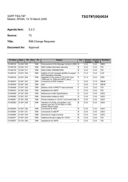
T2 Tdocs Spec CR Rev Ph Subject Cat Version- Version Workitem<br />
Current -New<br />
T2-<strong>00</strong>01<strong>00</strong> 23.040 <strong>00</strong>9 R99 Enhancement of the Message Content in SMS B 3.3.0 3.4.0 MMS<br />
T2-<strong>00</strong>0136 23.040 010 R99 SMS multiple information elements B 3.3.0 3.4.0 TEI<br />
T2-<strong>00</strong>0129 23.040 011 R99 SMS E-MAIL PARAMETERS B 3.3.0 3.4.0 TEI<br />
T2-<strong>00</strong>0134 23.041 <strong>00</strong>3 R99 Addition of LCS message identifier to support<br />
GPS Navigation message<br />
A 3.1.0 3.2.0 LCS<br />
T2-<strong>00</strong>0130 23.041 <strong>00</strong>4 R99 Adaptation of the scope of TS 23.041 from<br />
“GSM only” to “GSM and UMTS” part II<br />
F 3.1.0 3.2.0 CBS<br />
T2-<strong>00</strong><strong>00</strong>47 23.057 <strong>00</strong>1 R99 Corrections to WAP chapters F 3.0.0 3.1.0 MExE<br />
T2-<strong>00</strong><strong>00</strong>49 23.057 <strong>00</strong>2 R99 QoS F 3.0.0 3.1.0 MExE<br />
T2-<strong>00</strong><strong>00</strong>58 27.<strong>00</strong>7 023 R99 Deletion of the +CPROT? read command F 3.3.0 3.4.0 TEI<br />
T2-<strong>00</strong><strong>00</strong>72 27.<strong>00</strong>7 025 R99 Adaptations for UMTS F 3.3.0 3.4.0 TEI<br />
T2-<strong>00</strong><strong>00</strong>59 27.<strong>00</strong>7 026 R99 References to ASCI Specifications D 3.3.0 3.4.0 ASCI<br />
T2-<strong>00</strong><strong>00</strong>60 27.<strong>00</strong>7 027 R99 Abbreviations related to ASCI D 3.3.0 3.4.0 ASCI<br />
T2-<strong>00</strong><strong>00</strong>61 27.<strong>00</strong>7 028 R99 Priority indication in +CLCC, List Current Calls B 3.3.0 3.4.0 ASCI<br />
T2-<strong>00</strong><strong>00</strong>62 27.<strong>00</strong>7 029 R99 Indication of priority, sub-address, subaddress<br />
type and TS 91/TS92 in +CRC,<br />
Cellular Result Codes<br />
B 3.3.0 3.4.0 ASCI<br />
T2-<strong>00</strong><strong>00</strong>63 27.<strong>00</strong>7 030 R99 Commands for ASCI B 3.3.0 3.4.0 ASCI<br />
T2-<strong>00</strong><strong>00</strong>64 27.<strong>00</strong>7 031 R99 Commands for eMLPP B 3.3.0 3.4.0 ASCI<br />
T2-<strong>00</strong><strong>00</strong>65 27.<strong>00</strong>7 032 R99 Example for usage of priority B 3.3.0 3.4.0 ASCI<br />
T2-<strong>00</strong><strong>00</strong>71 27.<strong>00</strong>7 024 R99 Additional format( 4 digits) for +CCLK B 3.3.0 3.4.0 TEI<br />
T2-<strong>00</strong><strong>00</strong>57 27.010 <strong>00</strong>5 R99 Adaptations for UMTS F 3.2.0 3.3.0 TEI
<strong>3GPP</strong> TSG-T2 #8 / ETSI SMG4<br />
Puerto Vallarta, MEXICO, 1 - 4 Feb 2<strong>00</strong>0<br />
Document TSGT2#8(<strong>00</strong>)1<strong>00</strong><br />
CHANGE REQUEST<br />
23.040 CR <strong>00</strong>9<br />
e.g. for <strong>3GPP</strong> use the format TP-99xxx<br />
or for SMG, use the format P-99-xxx<br />
Please see embedded help file at the bottom of this<br />
page for instructions on how to fill in this form correctly.<br />
Current Version: 3.3.0<br />
GSM (AA.BB) or 3G (AA.BBB) specification number ↑ ↑ CR number as allocated by MCC support team<br />
For submission to: T#7 for approval X strategic (for SMG<br />
list expected approval meeting # here ↑ for information non-strategic use only)<br />
Form: CR cover sheet, version 2 for <strong>3GPP</strong> and SMG The latest version of this form is available from: ftp://ftp.3gpp.org/Information/CR-Form-v2.doc<br />
Proposed change affects: (U)SIM ME X UTRAN / Radio Core Network<br />
(at least one should be marked with an X)<br />
Source: T2 Date: 28 Jan 2<strong>00</strong>0<br />
Subject: Enhancement of the Message Content in SMS<br />
Work item:<br />
Messaging (Short Message Service (SMS))<br />
Category: F Correction Release: Phase 2<br />
A Corresponds to a correction in an earlier release Release 96<br />
(only one category B Addition of feature X Release 97<br />
shall be marked C Functional modification of feature Release 98<br />
with an X) D Editorial modification Release 99 X<br />
Release <strong>00</strong><br />
Reason for<br />
change:<br />
This CR proposes an enhancement of the message-contents in SMS. At the moment SMS users<br />
are not able to send more than plain text to each other. This proposal provides the users to make<br />
more exciting messages with features like formatting the text, sounds, small pictures and simple<br />
animations.<br />
This enhancement is based on standard mechanisms in GSM and is therefore backward<br />
compatible with older terminals. Terminals that do not have these extra features will still be able<br />
to present the text but not the extra information (e.g. formatting, pictures).<br />
Clauses affected: 2, 3.10, 9.2.3.24, 9.2.3.24.10<br />
Other specs Other 3G core specifications → List of CRs:<br />
affected: Other GSM core specifications → List of CRs:<br />
MS test specifications → List of CRs:<br />
BSS test specifications → List of CRs:<br />
O&M specifications → List of CRs:<br />
Other<br />
comments:<br />
help.doc<br />
2 Normative references<br />
The following documents contain provisions which, through reference in this text, constitute provisions of the present<br />
document.<br />
• References are either specific (identified by date of publication, edition number, version number, etc.) or nonspecific.<br />
• For a specific reference, subsequent revisions do not apply.<br />
• For a non-specific reference, the latest version applies.<br />
• A non-specific reference to an ETS shall also be taken to refer to later versions published as an EN with the same<br />
number.<br />
[1] GSM 01.04: "Digital cellular telecommunication system (Phase 2+); Abbreviations and<br />
acronyms".<br />
[2] GSM 02.03: "Digital cellular telecommunication system (Phase 2+); Teleservices supported by a<br />
GSM Public Land Mobile Network (PLMN)".<br />
[3] 3G TS 22.<strong>00</strong>4: "General on supplementary services".<br />
[4] 3G TS 22.041: " Operator determined barring".<br />
[5] GSM 03.02: "Digital cellular telecommunication system (Phase 2+); Network architecture".<br />
[6] 3G TS 23.<strong>00</strong>8: "Organization of subscriber data".<br />
[7] 3G TS 23.011: "Technical realization of supplementary services - General Aspects".<br />
[8] 3G TS 23.015: "Technical realisation of Operator Determined Barring (ODB)".<br />
[9] 3G TS 23.038: "Alphabets and language-specific information".<br />
[10] 3G TS 23.041: "Technical realization of Cell Broadcast Service (CBS)".<br />
[11] GSM 03.47 (ETR 354): "Digital cellular telecommunication system; Example protocol stacks for<br />
interconnecting Service Centre(s) (SC) and Mobile-services Switching Centre(s) (MSC)".<br />
[12] GSM 04.08: "Digital cellular telecommunication system (Phase 2+); Mobile radio interface layer 3<br />
specification".<br />
[13] 3G TS 24.011: "Short Message Service (SMS) support on mobile radio interface".<br />
[14] 3G TS 27.<strong>00</strong>5: "Use of Data Terminal Equipment - Data Circuit terminating Equipment (DTE -<br />
DCE) interface for Short Message Service (SMS) and Cell Broadcast Service (CBS)".<br />
[15] 3G TS 29.<strong>00</strong>2: "Mobile Application Part (MAP) specification".<br />
[16] GSM 11.11: "Digital cellular telecommunication system (Phase 2+); Specification of the<br />
Subscriber Identity Module - Mobile Equipment (SIM- ME) interface".<br />
[17] CCITT Recommendation E.164 (Blue Book): "Numbering plan for the ISDN era".<br />
[18] CCITT Recommendation E.163 (Blue Book): "Numbering plan for the international telephone<br />
service".<br />
[19] CCITT Recommendation Q.771: "Specifications of Signalling System No.7; Functional<br />
description of transaction capabilities".<br />
[20] CCITT Recommendation T.1<strong>00</strong> (Blue Book): "International information exchange for interactive<br />
videotex".
[21] CCITT Recommendation T.101 (Blue Book): "International interworking for videotex services".<br />
[22] CCITT Recommendation X.121 (Blue Book): "International numbering plan for public data<br />
networks".<br />
[23] CCITT Recommendation X.4<strong>00</strong> (Blue Book): "Message handling system and service overview".<br />
[24] ISO/IEC10646, "Universal Multiple-Octet Coded Character Set (USC); UCS2, 16 bit coding".<br />
[25] 3G TS 22.022: "Personalisation of GSM ME Mobile functionality specification - Stage 1".<br />
[26] 3G TS 23.042: "Compression Algorithm for Text Messaging Services”<br />
[27] 3G TS 23.060: "General Packet Radio Service (GPRS); Service description; Stage 2".<br />
[28] GSM 03.48: "Digital cellular telecommunications system (Phase 2+); Security Mechanisms for the<br />
SIM application toolkit; Stage 2"<br />
[29] 3G TR 21.905: "3G Vocabulary".<br />
[30] 3G TS 31.102: "Characteristics of the USIM application"<br />
[31] 3G TS 31.101: "UICC – Terminal interface; Physical and logical characteristics"<br />
[32] 3G TS 22.105: "Services and Service Capabilites"<br />
[33] Infrared Data Association. Specifications for Ir Mobile Communications (IrMC).<br />
iMelody.
3.10 Enhanced Messaging Service<br />
The Enhanced Messaging Service (EMS) is based upon the standard SMS, but with formatting added to the text. The<br />
formatting permits the message to contain simple animations, small pictures, small melodies and formatting of the text,<br />
everything mixed together into one message. This section lists the supported features. The coding mechanisms and<br />
formats are specified in section 9.2.3.24.10<br />
3.10.1 Text formatting<br />
The following text formatting features are supported:<br />
Alignment<br />
• Left (default)<br />
• Centre<br />
• Right<br />
Font size<br />
• Normal (default)<br />
• Large<br />
• Small<br />
Style<br />
• Normal (default)<br />
• Bold<br />
• Italic<br />
• Underlined<br />
• Strikethrough<br />
3.10.2 Pictures<br />
It is possible to include either a small (16*16 pixels ), large (32*32 pixels) or pictures of variable size. These pictures<br />
have neither animation nor grey scales, it is plain black and white. All pictures are user defined.<br />
If multiple pictures are received side by side, then they will be stitched together with no inter-character spacing. If a<br />
is inserted in the middle of multiple pictures, then the left margin of the pictures are vertically aligned. If two<br />
pictures that are of the same size are logically separate, they should be separated by a space or other characters.<br />
Maximum recommended pictures size usage of this technique : 96x64 (6 large pictures, with a CR in the middle). This<br />
unified picture is then formatted as one.
3.10.3 Animations<br />
Predefined<br />
There are number of predefined animations. These animations are not sent as animation over the air interface, only the<br />
identification of them. As soon as the position of the animation in the SM data is reached, the animation corresponding<br />
to the received number shall be displayed in a manner which is manufacturer specific..<br />
User Defined<br />
The user-defined animations consist of 4 pictures and there are two different sizes of these animations. The picture size<br />
of the small animations are 8*8 pixels and the large 16*16 pixels. These animations are sent over the air interface.<br />
3.10.4 Sound<br />
Predefined<br />
There are a number of predefined sounds. These sounds are not transferred over the air interface, only the identification<br />
of them. There are 10 different sounds that can be added in the message, and as soon as the sound mark is in focus (on<br />
the display), the sound will be played.<br />
User Defined<br />
The sender can define own melodies according to the iMelody format [33]. These melodies are transferred in the SM<br />
and can take up to 128 bytes.
9.2.3.9 TP-Protocol-Identifier (TP-PID)<br />
The TP-Protocol-Identifier parameter serves the purposes indicated in subclause 3.2.3. It consists of one octet, and the<br />
bits in the octet are used as follows:<br />
The MS shall interpret reserved or unsupported values as the value <strong>00</strong><strong>00</strong><strong>00</strong><strong>00</strong> but shall store them exactly as received.<br />
The SC may reject messages with a TP-Protocol-Identifier containing a reserved value or one which is not supported.<br />
bits usage<br />
7 6<br />
0 0 Assigns bits 0..5 as defined below<br />
0 1 Assigns bits 0..5 as defined below<br />
1 0 reserved<br />
1 1 Assigns bits 0-5 for SC specific use<br />
In the case where bit 7 = 0 and bit 6 = 0,<br />
bit 5 indicates telematic interworking:<br />
value = 0 : no interworking, but SME-to-SME protocol<br />
value = 1 : telematic interworking<br />
In the case of telematic interworking, the following five bit patterns in bits 4..0 are used to indicate different types of<br />
telematic devices:<br />
4.. .0<br />
<strong>00</strong><strong>00</strong>0 implicit - device type is specific to this SC, or can be concluded on the basis of the address<br />
<strong>00</strong><strong>00</strong>1 telex (or teletex reduced to telex format)<br />
<strong>00</strong>010 group 3 telefax<br />
<strong>00</strong>011 group 4 telefax<br />
<strong>00</strong>1<strong>00</strong> voice telephone (i.e. conversion to speech)<br />
<strong>00</strong>101 ERMES (European Radio Messaging System)<br />
<strong>00</strong>110 National Paging system (known to the SC)<br />
<strong>00</strong>111 Videotex (T.1<strong>00</strong> [20] /T.101 [21])<br />
01<strong>00</strong>0 teletex, carrier unspecified<br />
01<strong>00</strong>1 teletex, in PSPDN<br />
01010 teletex, in CSPDN<br />
01011 teletex, in analog PSTN<br />
011<strong>00</strong> teletex, in digital ISDN<br />
01101 UCI (Universal Computer Interface, ETSI DE/PS 3 01-3)<br />
01110..01111 (reserved, 2 combinations)<br />
1<strong>00</strong><strong>00</strong> a message handling facility (known to the SC)<br />
1<strong>00</strong>01 any public X.4<strong>00</strong>-based message handling system<br />
1<strong>00</strong>10 Internet Electronic Mail<br />
1<strong>00</strong>11..10111 (reserved, 5 combinations)<br />
11<strong>00</strong>0..11110 values specific to each SC, usage based on mutual agreement between the SME and the SC<br />
(7 combinations available for each SC)<br />
11111 A GSM/UMTS mobile station. The SC converts the SM from the received<br />
TP-Data-Coding-Scheme to any data coding scheme supported by that MS (e.g. the default).<br />
If bit 5 has value 1 in an SMS-SUBMIT PDU, it indicates that the SME is a telematic device of a type which is indicated<br />
in bits 4..0, and requests the SC to convert the SM into a form suited for that device type. If the destination network is<br />
ISDN, the SC must also select the proper service indicators for connecting to a device of that type.<br />
If bit 5 has value 1 in an SMS-DELIVER PDU, it indicates that the SME is a telematic device of a type which is<br />
indicated in bits 4..0.<br />
If bit 5 has value 0 in an SMS-DELIVER PDU, the value in bits 4..0 identifies the SM-AL protocol being used between<br />
the SME and the MS.
Note that for the straightforward case of simple MS-to-SC short message transfer the Protocol Identifier is set to the<br />
value 0.<br />
In the case where bit 7 = 0, bit 6 = 1, bits 5..0 are used as defined below<br />
5 .. . .0<br />
<strong>00</strong><strong>00</strong><strong>00</strong> Short Message Type 0<br />
<strong>00</strong><strong>00</strong>01 Replace Short Message Type 1<br />
<strong>00</strong><strong>00</strong>10 Replace Short Message Type 2<br />
<strong>00</strong><strong>00</strong>11 Replace Short Message Type 3<br />
<strong>00</strong>01<strong>00</strong> Replace Short Message Type 4<br />
<strong>00</strong>0101 Replace Short Message Type 5<br />
<strong>00</strong>0110 Replace Short Message Type 6<br />
<strong>00</strong>0111 Replace Short Message Type 7<br />
<strong>00</strong>1<strong>00</strong>0..011101 Reserved<br />
011110 Enhanced Message Service (EMS. Refer section 3.10)<br />
011111 Return Call Message<br />
1<strong>00</strong><strong>00</strong>0..111011 Reserved<br />
1111<strong>00</strong> ANSI-136 R-DATA<br />
111101 ME Data download<br />
111110 ME De-personalization Short Message<br />
111111 (U)SIM Data download<br />
A short message type 0 indicates that the ME must acknowledge receipt of the short message but may discard its<br />
contents.<br />
The Replace Short Message feature is optional for the ME and the (U)SIM but if implemented it shall be performed as<br />
described here.<br />
For MT short messages, on receipt of a short message from the SC, the MS shall check to see if the associated Protocol<br />
Identifier contains a Replace Short Message Type code.<br />
If such a code is present, then the MS shall check the originating address and replace any existing stored message having<br />
the same Protocol Identifier code and originating address with the new short message and other parameter values. If<br />
there is no message to be replaced, the MS shall store the message in the normal way. The MS may also check the SC<br />
address as well as the Originating Address. However, in a network which has multiple SCs, it is possible for a Replace<br />
Message type for a SM to be sent via different SCs and so it is recommended that the SC address should not be checked<br />
by the MS unless the application specifically requires such a check.<br />
If a Replace Short Message Type code is not present then the MS shall store the message in the normal way.<br />
In MO short messages the SC reacts similarly but only the address of the originating MS or any other source is checked<br />
The Enhanced Message Service PID value shall be set in a MO enhanced short message unless there is a need to set the<br />
PID to any other value (e.g for telematic interworking). In the event where the message contains one or more IE that<br />
could not be understood by the receiving SME, this PID value may be used to assist the receiving SME and/or the<br />
SMSC to identify such a message ( e.g for diagnostic purposes). It is not a mandatory requirement for the SMSC or<br />
receiving SME to process this PID value or for the SMSC to pass the value to the receiving SME.<br />
A Return Call Message indicates to the MS to inform the user that a call (e.g. a telephone call) can be established to the<br />
address specified within the TP-OA. The RP-OA contains the address of the SC as usual. The message content (if<br />
present) gives displayable information (e.g. the number of waiting voice messages). The message is handled in the same<br />
way as all other messages of the Replace Short Message Types.<br />
The ME De-personalization Short Message is a ME-specific message which instructs the ME to de-personalities the ME<br />
(see 3G TS 22.022 [25] ). The TP-DCS shall be set to Uncompressed, Default Alphabet, and Message Class 1<br />
(ME-specific), which corresponds to a bit coding of <strong>00</strong>01<strong>00</strong>01. The TP-UD field contains de-personalization<br />
information coded according to 3G TS 22.022 [25]. This information shall not be displayed by an ME which supports<br />
the scheme. The acknowledgement to this message is a SMS-DELIVER-REPORT for RP-ACK in which the<br />
TP-User-Data shall be coded according to 3G TS 22.022 [25].<br />
(U)SIM Data download is a facility whereby the ME must pass the short message in its entirety including all SMS<br />
elements contained in the SMS deliver to the (U)SIM using the mechanism described in GSM TS 11.11 [16] and 3G TS
31.102 [30]. The DCS shall be set to 8 bit message class 2 (either bit coding 1111 0110 or <strong>00</strong>010110). The entire user<br />
data field is available for (U)SIM Data download. If the DCS is not set to 8-bit message class 2 then the message shall<br />
be handled in the normal way by the ME.<br />
ME Data download is a facility whereby the ME shall process the short message in its entirety including all SMS<br />
elements contained in the SMS deliver to the ME. The DCS shall be set to message class 1. The entire user data field is<br />
available for ME data download.<br />
ANSI-136 R-DATA is a facility whereby the ME must pass the short message in its entirety, including all elements<br />
contained in the SMS DELIVER, to the (U)SIM using the mechanism described in GSM TS 11.14 [16] and 3G TS<br />
31.102 [30]. The DCS shall be set to 8-bit message class 2 (either bit coding 11110110 or <strong>00</strong>010110). If the DCS is not<br />
set to 8-bit message class 2 then the message shall be handled in the normal way by the ME.
9.2.3.24 TP-User Data (TP-UD)<br />
The length of the TP-User-Data field is defined in the PDU’s of the SM-TL ( see subclause 9.2.2 ).<br />
The TP-User-Data field may comprise just the short message itself or a Header in addition to the short message<br />
depending upon the setting of TP-UDHI.<br />
Where the TP-UDHI value is set to 0 the TP-User-Data field comprises the short message only, where the user data can<br />
be 7 bit (default alphabet) data, 8 bit data, or 16 bit (UCS2 [24]) data.<br />
Where the TP-UDHI value is set to 1 the first octets of the TP-User-Data field contains a Header in the following order<br />
starting at the first octet of the TP-User-Data field.<br />
Irrespective of whether any part of the User Data Header is ignored or discarded, the MS shall always store the entire<br />
TPDU exactly as received.<br />
FIELD LENGTH<br />
Length of User Data Header 1 octet<br />
Information-Element-Identifier "A" 1 octet<br />
Length of Information-Element "A" 1 octet<br />
Information-Element "A" Data 1 to "n" octets<br />
Information-Element-Identifier "B" 1 octet<br />
Length of Information-Element "B" 1 octet<br />
Information-Element "B" Data 1 to "n" octets<br />
Information-Element-Identifier "n" 1 octet<br />
Length of Information-Element "n" 1 octet<br />
Information-Element "n" Data 1 to "n" octets<br />
The diagram below shows the layout of the TP-User-Data-Length and the TP-User-Data for uncompressed GSM 7 bit<br />
default alphabet data. The UDHL field is the first octet of the TP-User-Data content of the Short Message.<br />
O ctets<br />
UDL UDHL IEIa IEIDLa IEDa IEIb ......... IEIn IEDLn IEDn Fill bits SM (7bit data)<br />
Length Indicator<br />
Length Indicator<br />
Total num ber of O ctets<br />
Total number of Septets<br />
Figure 9.2.3.24 (a)<br />
Octets<br />
Septet Boundary
The diagram below shows the layout of the TP-User-Data-Length and the TP-User-Data for uncompressed 8 bit data or<br />
uncompressed UCS2 data. The UDHL field is the first octet of the TP-User-Data content of the Short Message.<br />
Octets<br />
UDL UDHL IEIa IEIDLa IEDa IEIb ......... IEIn IEDLn IEDn<br />
Length Indicator<br />
Length Indicator<br />
Total num ber of O ctets<br />
Total number of Octets<br />
Figure 9.2.3.24 (b)<br />
Octets<br />
SM (8 bit data<br />
or UCS-2 data)<br />
Octet Boundary<br />
The diagram below shows the layout of the TP-User-Data-Length and the TP-User-Data for compressed GSM 7 bit<br />
default alphabet data, compressed 8 bit data or compressed UCS2 data. The UDHL field is the first octet of the TP-<br />
User-Data content of the Short Message.<br />
Octets<br />
UDL UDHL IEIa IEIDLa IEDa IEIb ......... IEIn IEDLn IEDn Compressed SM (octets)<br />
Length Indicator<br />
Length Indicator<br />
Total num ber of O ctets<br />
Total num ber of O ctets<br />
Figure 9.2.3.24 (c)<br />
Octets<br />
Octet Boundary<br />
The definition of the TP-User-Data-Length field which immediately precedes the "Length of User Data Header" is<br />
unchanged and shall therefore be the total length of the TP-User-Data field including the Header, if present. (see<br />
9.2.3.16)<br />
The "Length-of-Information-Element" fields shall be the integer representation of the number of octets within its<br />
associated "Information-Element-Data" field which follows and shall not include itself in its count value.<br />
The "Length-of-User-Data-Header" field shall be the integer representation of the number of octets within the<br />
"User-Data-Header" information fields which follow and shall not include itself in its count or any fill bits which may be<br />
present (see text below).<br />
Information Elements may appear in any order and need not necessarily follow the order used in this specification. If<br />
Information Elements are duplicated (either with the same or different content) then the contents of the last occurrence
of the Information Element shall be used. If the length of the User Data Header overall is such that there appear to be<br />
too few or too many octets in the final Information Element then the whole User Data Header shall be ignored.<br />
If any reserved values are received within the content of any Information Element then that part of the Information<br />
Element shall be ignored.
The Information Element Identifier octet shall be coded as follows:<br />
VALUE (hex) MEANING<br />
<strong>00</strong> Concatenated short messages, 8-bit reference number<br />
01 Special SMS Message Indication<br />
02 Reserved<br />
03 Value not used to avoid misinterpretation as character<br />
04 Application port addressing scheme, 8 bit address<br />
05 Application port addressing scheme, 16 bit address<br />
06 SMSC Control Parameters<br />
07 UDH Source Indicator<br />
08 Concatenated short message, 16-bit reference number<br />
09 Wireless Control Message Protocol<br />
0A Text Formatting<br />
0B Predefined Sound<br />
0C User Defined Sound (iMelody max 128 bytes)<br />
0D Predefined Animation<br />
0E Large Animation (16*16 times 4 = 32*4 =128 bytes)<br />
0F Small Animation (8*8 times 4 = 8*4 =32 bytes )<br />
10 Large Picture (32*32 = 128 bytes)<br />
11 Small Picture (16*16 = 32 bytes)<br />
12 Variable Picture<br />
13-1F Reserved for future EMS features (see section 3.10)<br />
2<strong>00</strong>A-6F Reserved for future use<br />
70-7F (U)SIM Toolkit Security Headers<br />
80 - 9F SME to SME specific use<br />
A0 - BF Reserved for future use<br />
C0 - DF SC specific use<br />
E0 - FF Reserved for future use<br />
A receiving entity shall ignore (i.e. skip over and commence processing at the next information element) any<br />
information element where the IEI is Reserved or not supported. The receiving entity calculates the start of the next<br />
information element by looking at the length of the current information element and skipping that number of octets.<br />
The SM itself may be coded as 7, 8 or 16 bit data.<br />
If 7 bit data is used and the TP-UD-Header does not finish on a septet boundary then fill bits are inserted after the last<br />
Information Element Data octet up to the next septet boundary so that there is an integral number of septets for the entire<br />
TP-UD header. This is to ensure that the SM itself starts on an septet boundary so that an earlier Phase mobile shall be<br />
capable of displaying the SM itself although the TP-UD Header in the TP-UD field may not be understood.
It is optional to make the first character of the SM itself a Carriage Return character encoded according to the default 7<br />
bit alphabet so that earlier Phase mobiles, which do not understand the TP-UD-Header, shall over-write the displayed<br />
TP-UD-Header with the SM itself.<br />
If 16 bit (USC2) data is used then padding octets are not necessary. The SM itself shall start on an octet boundary.<br />
If 8 bit data is used then padding is not necessary. An earlier Phase mobile shall be able to display the SM itself<br />
although the TP-UD header may not be understood.<br />
It is also possible for mobiles not wishing to support the TP-UD header to check the value of the TP-UDHI bit in the<br />
SMS-Deliver PDU and the first octet of the TP-UD field and skip to the start of the SM and ignore the TP-UD header.
9.2.3.24.10 Enhanced Messaging Service<br />
9.2.3.24.10.1 EMS Coding<br />
Enhanced Messaging is based on standard mechanism in GSM SMS messaging. The first mechanism is called user data<br />
header (TP-UDH), which makes it possible to include binary data in a normal SM prior the text message itself (chapter<br />
9.2.3.24). The binary data is in the TP-UD field (message), which means that it steels a part of the 140 bytes.<br />
Each object within the SM shall be identified by a IE in the TP-UD Header. The IE will contain a octet (refer to<br />
section 9.2.3.24.10.1) that identifies the absolute position of the object within and from the beginning of the SM data. In<br />
case of formatting text, an additional octet will give the number of characters for which the formatting applies.<br />
Next mechanism that is used is concatenation, see chapter 9.2.3.24.1. This mechanism permits longer messages than<br />
140 bytes, in fact 255 messages a 140 bytes each can be concatenated to one message up to about 38k bytes.<br />
EMS IEs of the same type may occur more than once in a single message or one segment of a concatenated SM.<br />
9.2.3.24.10.1.1 Text Formatting<br />
The Information-Element-Data octet(s) shall be coded as follows.<br />
Octet 1 Start position of the text formatting. Set to the number of characters after the formatting shall be applied<br />
from the beginning of the SM data.<br />
This octet shall be coded as an integer value in the range 0 (beginning of the SM data) to the maximum number<br />
of characters included in the SM data of one single SM or one segment of a concatenated SM<br />
Octet 2 Text formatting length. Gives the number of formatted characters<br />
This octet shall be coded as an integer value in the range 1 to the maximum number of characters for which the<br />
formatting applies in one single SM or one segment of a concatenated SM.<br />
Octet 3 formatting mode value coded as following :<br />
Octet 3 : Bit 7 Bit 6 Bit 5 Bit 4 Bit 3 Bit 2 Bit 1 Bit 0<br />
Bit 1 Bit 0 *Alignment<br />
0 0 Left (default)<br />
0 1 Center<br />
1 0 Right<br />
1 1 reserved<br />
*in case formatting text is inserted on the same line as previous non formatting text or with a different<br />
mode value, the alignment value shall be set to the same value as the previous formatted predefined<br />
object.<br />
Bit 3 Bit 2 Font Size<br />
0 0 Normal (default)<br />
0 1 Large<br />
1 0 Small<br />
1 1 reserved<br />
Bit 4 Style bold<br />
1 Bold on<br />
0 Bold off<br />
Bit 5 Style Italic<br />
1 Italic on<br />
0 Italic off
Bit 6 Style Underlined<br />
1 Underlined on<br />
0 Underlined off<br />
Bit 7 Style Strikethrough<br />
1 Strikethrough on<br />
0 Strikethrough off<br />
If bit 4,5,6 and 7 are set to 0, it will mean normal style (default).<br />
9.2.3.24.10.1.2 Predefined Sound<br />
The Information-Element-Data octet(s) shall be coded as follows.<br />
Octet 1 position indicating in the SM data the instant after which the sound shall be played. It will be set to the<br />
number of characters from the beginning of the SM data after which the sound shall be played.<br />
This octet shall be coded as an integer value in the range 0 (beginning of the SM data) to the maximum number<br />
of characters included in the SM data of one single SM or one segment of a concatenated SM<br />
Octet 2 sound number. Shall be encoded as a integer value.<br />
9.2.3.24.10.1.3 User Defined Sound<br />
The Information-Element-Data octet(s) shall be coded as follows.<br />
Octet 1 position indicating in the SM data the instant the after which the sound shall be played (refer to section<br />
9.2.3.24.10.1.2).<br />
Octet 2-n Protocol Data Unit as described in section 9.2.3.24.10.3.1<br />
This octet(s) shall contain a User Defined Sound.<br />
9.2.3.24.10.1.4 Predefined Animation<br />
The Information-Element-Data octet(s) shall be coded as follows.<br />
Octet 1 position indicating in the SM data the instant the animation shall be displayed. Set to the number of<br />
characters from the beginning of the SM data after which the animation shall be displayed.<br />
This octet shall be coded as an integer value in the range 0 (beginning of the SM data) to the maximum number<br />
of characters included in the SM data of one single SM or one segment of a concatenated SM<br />
Octet 2 animation number. Shall be encoded as an integer value.<br />
9.2.3.24.10.1.5 Large Animation<br />
The Information-Element-Data octet(s) shall be coded as follows.<br />
Octet 1 position indicating the instant the animation shall be displayed in the SM data<br />
(refer section 9.2.3.24.10.1.4).<br />
Octet 2-n Protocol Data Unit as described in section 9.2.3.24.10.3.3<br />
This octet(s) shall contain a Large Animation.<br />
9.2.3.24.10.1.6 Small Animation<br />
The Information-Element-Data octet(s) shall be coded as follows.<br />
Octet 1 position indicating the instant the animation shall be displayed in the SM data<br />
(refer section 9.2.3.24.10.1.4).
Octet 2-n Protocol Data Unit as described in section 9.2.3.24.10.3.3<br />
This octet(s) shall contain a Small Animation.<br />
9.2.3.24.10.1.7 Large Picture<br />
The Information-Element-Data octet(s) shall be coded as follows.<br />
Octet 1 position indicating in the SM data the instant the picture shall be displayed. Set to the number of<br />
characters from the beginning of the SM data after which the picture shall be displayed.<br />
This octet shall be coded as an integer value in the range 0 (beginning of the SM data) to the maximum number<br />
of characters included in the SM data of one single SM or one segment of a concatenated SM<br />
Octet 2-n Protocol Data Unit as described in 9.2.3.24.10.3.2<br />
This octet(s) shall contain a Large Picture.<br />
9.2.3.24.10.1.8 Small Picture<br />
The Information-Element-Data octet(s) shall be coded as follows.<br />
Octet 1 position indicating in the SM data the instant the picture shall be displayed in the SM data<br />
(refer section 9.2.3.24.10.1.7)<br />
Octet 2-n Protocol Data Unit as described in section 9.2.3.24.10.3.2<br />
This octet(s) shall contain a Small Picture.<br />
9.2.3.24.10.1.9 Variable Picture<br />
The Information-Element-Data octet(s) shall be coded as follows.<br />
Octet 1 position indicating in the SM data the instant the picture shall be displayed in the SM data<br />
(refer section 9.2.3.24.10.1.7)<br />
Octet 2 Horizontal dimension of the picture.<br />
This octet shall contain the horizontal number of 8 pixels i.e. this value shall be multiplied by 8 to get the<br />
whole number of horizontal pixels.<br />
Octet 3 Vertical dimension of the picture.<br />
This octet shall contain the vertical number of pixels.<br />
Octet 4-n Protocol Data Unit as described in section 9.2.3.24.10.3.2<br />
This octet(s) shall contain a Variable Picture line by line from top left to bottom right.<br />
The values of the horizontal and vertical dimensions must be chosen properly by the sending entity. If the calculated size<br />
of this IE exceeds the limits of a single SM or segment it shall be discarded by the receiving entity.<br />
9.2.3.24.10.2 Examples of EMS coding<br />
All IE values in the TP-UD are hexadecimal values.<br />
9.2.3.24.10.2.1 Example of Basic text formatting and predefined EMS coding<br />
An example of the basic concept of coding is given as follows:<br />
TP-UDHI=1<br />
SMS User Data Header: UDHL=05, IEI=0A, IEDL=03, IED1=0F, IED2=12, IED3=10
SMS User Data: This is a text with bold option on following with normal text.<br />
Should be displayed as:<br />
This is a text with bold<br />
option on following with<br />
normal text.<br />
It is also possible to add predefined sounds in the message.<br />
Example:<br />
TP-UDHI=1<br />
SMS User Data Header: UDHL=08, IEI=0B, IEDL=02, IED1=09,, IEI=0B, IEDL=2, IED1=1C,<br />
<br />
SMS User Data: This is a message with two different sounds<br />
The sound nr5 shall be played after the 9 th received character (“a”) and sound nr7 shall be played after the 28 th received<br />
character (“e”).<br />
9.2.3.24.10.2.2 Example of User defined Objects EMS coding<br />
Example of a message including one small picture is coded as follows:<br />
TP UDHI=1<br />
SMS User Data Header: UDHL=24, IEI=11, IEIDL=22, IED1=08, < ☎ (small picture 32bytes)><br />
SMS User Data: Hello!One small picture in here<br />
Should be displayed as :<br />
Hello!<br />
☎<br />
One small picture in here<br />
If the message starts with , then the “unreadable” data in an old terminal will be overwritten by the text, and the<br />
user will not see any strange characters. It is possible to insert the same picture several times in the same message. In<br />
that case, the TP-UD header shall contain as many IE as the number of occurrences contained in the SM or one segment<br />
of a concatenated message. Using defined elements will normally imply that more than one SM is required and therefore<br />
concatenation is required.<br />
9.2.3.24.10.2.3 Concatenation of SMS messages<br />
Concatenated messages are required in most cases required when using several types of EMS elements, since it is only<br />
possible to send one large picture/large animation/melody in one single SM. After including either of these elements,<br />
there are only 4 (or 9 if no concatenation is used) characters left to the text part, and this is usually too little.<br />
If one or more objects are embedded in one segment of a concatenated message, the IE octet indicating its/their position<br />
within the SM data cannot be set to a value that would refer to a position in the next segment(s) so that received
segments should be processed before all of them have been received. It means that a formatting text that could not be<br />
conveyed in one segment shall be split in as many segments as necessary . In that case, the IE relating to the formatting<br />
shall be repeated in all the segments in which it will apply.<br />
Example of a message including 2 Large Pictures, 4 Small animations and 2 User defined Melodies together with some<br />
text.<br />
The EMS message: Hello All, This is a real Enhanced Message . I can send and receive really advanced EMS messages<br />
Isn’t it impressive? /Lars
This EMS message has to use concatenated messages and the SM will tyipically contain the following data:<br />
SM User Data Header User Data<br />
1 IEI=10 (Large Picture)<br />
IED1=<strong>00</strong> (beginning of the SM)<br />
<br />
2 IEI=0C (User Defined Sound)<br />
IED1=<strong>00</strong> (beginning of the SM)<br />
<br />
3 IEI=0F (Small Animation)<br />
IED1=24 (36 th position)<br />
<br />
IEI=0F (Small Animation)<br />
IED1=2F (47 th position)<br />
<br />
4 IEI=0F (Small Animation)<br />
IED1=07 (7 th position)<br />
<br />
IEI=0F (Small Animation)<br />
IED1=25 (37 th position)<br />
<br />
5 IEI=0C (User Defined Sound)<br />
IED1=<strong>00</strong> (beginning of the SM)<br />
<br />
6 IEI=10 (Large Picture)<br />
IED1=<strong>00</strong> (beginning of the SM)<br />
<br />
9.2.3.24.10.3 EMS Formats<br />
9.2.3.24.10.3.1 Sounds<br />
Predefined Sounds<br />
[]<br />
Hello<br />
All, This is a real Enhanced Message.I can send and<br />
receive really advanced EMS messages. Isn’t it<br />
impressive? /Lars.<br />
[]<br />
There are a number of fixed predefined sounds. Each sound nr corresponds to a specific sound according to the table<br />
below. The presentations of these sounds are manufacturer specific.<br />
Sound nr Description<br />
0 Chimes high<br />
1 Chimes low<br />
2 Ding<br />
3 TaDa<br />
4 Notify<br />
5 Drum<br />
6 Claps
7 FanFar<br />
8 Chord high<br />
9 Chord low<br />
User defined sounds<br />
The user defined sounds are coded according to the iMelody format[33]. The maximum length of a sound is 128 bytes.<br />
9.2.3.24.10.3.2 Pictures<br />
Pictures are coded from upper left to lower right and in each byte the most significant bit represent the pixel at the left.<br />
The pictures are plain black and white, no colours or grey scales are supported. The bitvalue “0” represents a white pixel<br />
and the bitvalue “1” represents a black pixel.<br />
Example 16*16 picture<br />
Byte 1 Byte 2<br />
Byte 3 Byte 4<br />
… …<br />
… …<br />
Byte 31 Byte 32<br />
9.2.3.24.10.3.3 Animation<br />
Predefined<br />
There are a number of predefined animations. Each animation nr corresponds to a specific animation according to the<br />
table below. The way of displaying the animation is manufacturer specific.<br />
Animation nr Description<br />
0 I am ironic, flirty<br />
1 I am glad<br />
2 I am sceptic<br />
3 I am sad<br />
4 WOW!<br />
5 I am crying<br />
User Defined<br />
Animations are coded as 4 sequential pictures, with the first picture sent first.
<strong>3GPP</strong>/SMG Meeting T2 #8 / ETSI SMG4<br />
Puerto Vallarta, Mexico, 1-4 Feb 2<strong>00</strong>0<br />
Document T2-<strong>00</strong>0136<br />
CHANGE REQUEST<br />
23.040 CR 010<br />
e.g. for <strong>3GPP</strong> use the format TP-99xxx<br />
or for SMG, use the format P-99-xxx<br />
Please see embedded help file at the bottom of this<br />
page for instructions on how to fill in this form correctly.<br />
Current Version: 3.3.0<br />
GSM (AA.BB) or 3G (AA.BBB) specification number ↑ ↑ CR number as allocated by MCC support team<br />
For submission to: T#7 for approval X strategic (for SMG<br />
for information non-strategic use only)<br />
list expected approval meeting # here<br />
↑<br />
Form: CR cover sheet, version 2 for <strong>3GPP</strong> and SMG The latest version of this form is available from: ftp://ftp.3gpp.org/Information/CR-Form-v2.doc<br />
Proposed change affects: (U)SIM ME X UTRAN / Radio Core Network<br />
(at least one should be marked with an X)<br />
Source: T2 Date: 02.02.2<strong>00</strong>0<br />
Subject: Multiple Information Elements<br />
Work item: SMS ENHANCEMENTS AND IMPROVEMENTS<br />
Category: F Correction Release: Phase 2<br />
A Corresponds to a correction in an earlier release Release 96<br />
(only one category B Addition of feature X Release 97<br />
shall be marked C Functional modification of feature Release 98<br />
with an X) D Editorial modification Release 99 X<br />
Release <strong>00</strong><br />
Reason for<br />
change:<br />
Clauses affected: 9.2.3.24<br />
The existing specification does not permit multiple instances of any Information<br />
Element type to be used within a User-Data-Header. SMS enhancements that benefit<br />
from the possibility of multiple use of new Information Elements are now being<br />
introduced, and consequently this overall restriction should be relaxed.<br />
Other specs Other 3G core specifications → List of CRs:<br />
affected: Other GSM core<br />
specifications<br />
→ List of CRs:<br />
MS test specifications → List of CRs:<br />
BSS test specifications → List of CRs:<br />
O&M specifications → List of CRs:<br />
Other<br />
comments:<br />
help.doc<br />
The handling of Information Elements defined in the existing specification is unchanged<br />
by this CR. Therefore the CR is proposed as Category B.<br />
Note: Although change bars appear at the diagrams in this CR the diagrams are<br />
unchanged.<br />
9.2.3.24 TP-User Data (TP-UD)<br />
The length of the TP-User-Data field is defined in the PDU’s of the SM-TL ( see subclause 9.2.2 ).<br />
The TP-User-Data field may comprise just the short message itself or a Header in addition to the short message depending upon the<br />
setting of TP-UDHI.<br />
Where the TP-UDHI value is set to 0 the TP-User-Data field comprises the short message only, where the user data can be 7 bit<br />
(default alphabet) data, 8 bit data, or 16 bit (UCS2) data.<br />
Where the TP-UDHI value is set to 1 the first octets of the TP-User-Data field contains a Header in the following order starting at<br />
the first octet of the TP-User-Data field.<br />
Irrespective of whether any part of the User Data Header is ignored or discarded, the MS shall always store the entire TPDU<br />
exactly as received.<br />
FIELD LENGTH<br />
Length of User Data Header 1 octet<br />
Information-Element-Identifier "A" 1 octet<br />
Length of Information-Element "A" 1 octet<br />
Information-Element "A" Data 1 to "n" octets<br />
Information-Element-Identifier "B" 1 octet<br />
Length of Information-Element "B" 1 octet<br />
Information-Element "B" Data 1 to "n" octets<br />
Information-Element-Identifier "n" 1 octet<br />
Length of Information-Element "n" 1 octet<br />
Information-Element "n" Data 1 to "n" octets<br />
The diagram below shows the layout of the TP-User-Data-Length and the TP-User-Data for uncompressed GSM 7 bit default<br />
alphabet data. The UDHL field is the first octet of the TP-User-Data content of the Short Message.<br />
O ctets<br />
UDL UDHL IEIa IEIDLa IEDa IEIb ......... IEIn IEDLn IEDn Fill bits SM (7bit data)<br />
Length Indicator<br />
Length Indicator<br />
Total num ber of O ctets<br />
Total number of Septets<br />
Figure 9.2.3.24 (a)<br />
Octets<br />
Septet Boundary<br />
The diagram below shows the layout of the TP-User-Data-Length and the TP-User-Data for uncompressed 8 bit data or<br />
uncompressed UCS2 data. The UDHL field is the first octet of the TP-User-Data content of the Short Message.
Octets<br />
UDL UDHL IEIa IEIDLa IEDa IEIb ......... IEIn IEDLn IEDn<br />
Length Indicator<br />
Length Indicator<br />
Total num ber of O ctets<br />
Total number of Octets<br />
Figure 9.2.3.24 (b)<br />
Octets<br />
SM (8 bit data<br />
or UCS-2 data)<br />
Octet Boundary<br />
The diagram below shows the layout of the TP-User-Data-Length and the TP-User-Data for compressed GSM 7 bit default<br />
alphabet data, compressed 8 bit data or compressed UCS2 data. The UDHL field is the first octet of the TP-User-Data content of<br />
the Short Message.<br />
Octets<br />
Octets<br />
UDL UDHL IEIa IEIDLa IEDa IEIb ......... IEIn IEDLn IEDn Compressed SM (octets)<br />
Length Indicator<br />
Length Indicator<br />
Total num ber of O ctets<br />
Total num ber of O ctets<br />
Figure 9.2.3.24 (c)<br />
Octet Boundary<br />
The definition of the TP-User-Data-Length field which immediately precedes the "Length of User Data Header" is unchanged and<br />
will therefore be the total length of the TP-User-Data field including the Header, if present. (see 9.2.3.16)<br />
The "Length-of-Information-Element" fields shall be the integer representation of the number of octets within its associated<br />
"Information-Element-Data" field which follows and shall not include itself in its count value.<br />
The "Length-of-User-Data-Header" field shall be the integer representation of the number of octets within the "User-Data-Header"<br />
information fields which follow and shall not include itself in its count or any fill bits which may be present (see text below).<br />
Information Elements may appear in any order and need not necessarily follow the order used in this specification.<br />
In the case where there are no multiple instances of any Information Element type: If Information Elements are duplicated (either<br />
with the same or different content),within one single SM or within one segment of a concatenated message then the contents of the<br />
last occurrence of the Information Element shall be used.<br />
In the case where there are multiple instances of any Information Element type: If certain types of Information Elements are<br />
duplicated (either with the same or different content) within one single SM or within one segment of a concatenated message and
there is a contradiction in meaning (e.g. more than one Special Message Indication for voice) or there is a contradiction of<br />
Information Element types (e.g. an 8bit port address and a 16bit port address), then the contents of the last occurrence of the<br />
Information Element shall be used. Other types of Information Elements may occur more than once when there is additional<br />
information of the same type to be conveyed. The individual specifications for each Information Element will state if multiple use<br />
is permitted and in such a case will also indicate the maximum number of occurrences within one User Data Header.<br />
If the length of the User Data Header overall is such that there appear to be too few or too many octets in the final Information<br />
Element then the whole User Data Header shall be ignored.<br />
If any reserved values are received within the content of any Information Element then that part of the Information Element shall<br />
be ignored.
The Information Element Identifier octet shall be coded as follows:<br />
VALUE (hex) MEANING<br />
<strong>00</strong> Concatenated short messages, 8-bit reference number<br />
01 Special SMS Message Indication<br />
02 Reserved<br />
03 Value not used to avoid misinterpretation as character<br />
04 Application port addressing scheme, 8 bit address<br />
05 Application port addressing scheme, 16 bit address<br />
06 SMSC Control Parameters<br />
07 UDH Source Indicator<br />
08 Concatenated short message, 16-bit reference number<br />
09 Wireless Control Message Protocol<br />
0A-6F Reserved for future use<br />
70-7F SIM Toolkit Security Headers<br />
80 - 9F SME to SME specific use<br />
A0 - BF Reserved for future use<br />
C0 - DF SC specific use<br />
E0 - FF Reserved for future use<br />
A receiving entity shall ignore (i.e. skip over and commence processing at the next information element) any information element<br />
where the IEI is Reserved or not supported. The receiving entity calculates the start of the next information element by looking at<br />
the length of the current information element and skipping that number of octets.<br />
The SM itself may be coded as 7, 8 or 16 bit data.<br />
If 7 bit data is used and the TP-UD-Header does not finish on a septet boundary then fill bits are inserted after the last Information<br />
Element Data octet up to the next septet boundary so that there is an integral number of septets for the entire TP-UD header. This is<br />
to ensure that the SM itself starts on an septet boundary so that an earlier Phase mobile will be capable of displaying the SM itself<br />
although the TP-UD Header in the TP-UD field may not be understood.<br />
It is optional to make the first character of the SM itself a Carriage Return character encoded according to the default 7 bit alphabet<br />
so that earlier Phase mobiles, which do not understand the TP-UD-Header, will over-write the displayed TP-UD-Header with the<br />
SM itself.<br />
If 16 bit (USC2) data is used then padding octets are not necessary. The SM itself will start on an octet boundary.<br />
If 8 bit data is used then padding is not necessary. An earlier Phase mobile will be able to display the SM itself although the<br />
TP-UD header may not be understood.<br />
It is also possible for mobiles not wishing to support the TP-UD header to check the value of the TP-UDHI bit in the SMS-Deliver<br />
PDU and the first octet of the TP-UD field and skip to the start of the SM and ignore the TP-UD header.
<strong>3GPP</strong>/SMG Meeting T2 #8 / ETSI SMG4<br />
Puerto Vallarta, Mexico, 1 - 4 Feb 2<strong>00</strong>0<br />
Document T2(<strong>00</strong>)0129<br />
CHANGE REQUEST<br />
23.040 CR 011<br />
e.g. for <strong>3GPP</strong> use the format TP-99xxx<br />
or for SMG, use the format P-99-xxx<br />
Please see embedded help file at the bottom of this<br />
page for instructions on how to fill in this form correctly.<br />
Current Version: 3.3.0<br />
GSM (AA.BB) or 3G (AA.BBB) specification number ↑ ↑ CR number as allocated by MCC support team<br />
For submission to: TSG-T#7 for approval X Strategic (for SMG<br />
for information non-strategic use only)<br />
list expected approval meeting # here<br />
↑<br />
Form: CR cover sheet, version 2 for <strong>3GPP</strong> and SMG The latest version of this form is available from: ftp://ftp.3gpp.org/Information/CR-Form-v2.doc<br />
Proposed change affects: (U)SIM ME X UTRAN / Radio Core Network<br />
(at least one should be marked with an X)<br />
Source: T2 Date: 30.1.2<strong>00</strong>0<br />
Subject: SMS E-MAIL PARAMETERS<br />
Work item: SMS ENHANCEMENTS AND IMPROVEMENTS<br />
Category: F Correction Release: Phase 2<br />
A Corresponds to a correction in an earlier release Release 96<br />
(only one category B Addition of feature X Release 97<br />
shall be marked C Functional modification of feature Release 98<br />
with an X) D Editorial modification Release 99 X<br />
Release <strong>00</strong><br />
Reason for<br />
change: The existing 23.040 defines how certain e-mail parameters, such as an e-mail address<br />
and an e-mail subject, may be conveyed within the user-data of a short message.<br />
However, this mechanism is really only suitable for mobiles with simple text messaging<br />
facilities where the input/output is directly controlled by the human user.<br />
In the case of more advanced mobile equipment which supports concatenated short<br />
messages and has a higher layer application process for e-mail, it is very desirable to<br />
support the full RFC 822 e-mail header parameters within User-Data-Header<br />
mechanism. The improved structure should guarantee unambiguous processing as<br />
well as smooth and simple interworking between the internet and the mobile<br />
environment..<br />
Clauses affected: 2. / 3.8 / 9.2.3.24<br />
Other specs Other 3G core specifications → List of CRs:<br />
affected: Other GSM core<br />
specifications<br />
→ List of CRs:<br />
MS test specifications → List of CRs:<br />
BSS test specifications → List of CRs:<br />
O&M specifications → List of CRs:<br />
Other<br />
comments:
help.doc<br />
2 Normative references<br />
The following documents contain provisions which, through reference in this text, constitute provisions of the present document.<br />
• References are either specific (identified by date of publication, edition number, version number, etc.) or non-specific.<br />
• For a specific reference, subsequent revisions do not apply.<br />
• For a non-specific reference, the latest version applies.<br />
• A non-specific reference to an ETS shall also be taken to refer to later versions published as an EN with the same number.<br />
[1] GSM 01.04: "Digital cellular telecommunication system (Phase 2+); Abbreviations and acronyms".<br />
[2] GSM 02.03: "Digital cellular telecommunication system (Phase 2+); Teleservices supported by a GSM Public<br />
Land Mobile Network (PLMN)".<br />
[3] 3G TS 22.<strong>00</strong>4: "General on supplementary services".<br />
[4] 3G TS 22.041: " Operator determined barring".<br />
[5] GSM 03.02: "Digital cellular telecommunication system (Phase 2+); Network architecture".<br />
[6] 3G TS 23.<strong>00</strong>8: "Organization of subscriber data".<br />
[7] 3G TS 23.011: "Technical realization of supplementary services - General Aspects".<br />
[8] 3G TS 23.015: "Technical realisation of Operator Determined Barring (ODB)".<br />
[9] 3G TS 23.038: "Alphabets and language-specific information".<br />
[10] 3G TS 23.041: "Technical realization of Cell Broadcast Service (CBS)".<br />
[11] GSM 03.47 (ETR 354): "Digital cellular telecommunication system; Example protocol stacks for<br />
interconnecting Service Centre(s) (SC) and Mobile-services Switching Centre(s) (MSC)".<br />
[12] GSM 04.08: "Digital cellular telecommunication system (Phase 2+); Mobile radio interface layer 3<br />
specification".<br />
[13] 3G TS 24.011: "Short Message Service (SMS) support on mobile radio interface".<br />
[14] 3G TS 27.<strong>00</strong>5: "Use of Data Terminal Equipment - Data Circuit terminating Equipment (DTE - DCE)<br />
interface for Short Message Service (SMS) and Cell Broadcast Service (CBS)".<br />
[15] 3G TS 29.<strong>00</strong>2: "Mobile Application Part (MAP) specification".<br />
[16] GSM 11.11: "Digital cellular telecommunication system (Phase 2+); Specification of the Subscriber Identity<br />
Module - Mobile Equipment (SIM- ME) interface".<br />
[17] CCITT Recommendation E.164 (Blue Book): "Numbering plan for the ISDN era".<br />
[18] CCITT Recommendation E.163 (Blue Book): "Numbering plan for the international telephone service".<br />
[19] CCITT Recommendation Q.771: "Specifications of Signalling System No.7; Functional description of<br />
transaction capabilities".<br />
[20] CCITT Recommendation T.1<strong>00</strong> (Blue Book): "International information exchange for interactive videotex".<br />
[21] CCITT Recommendation T.101 (Blue Book): "International interworking for videotex services".<br />
[22] CCITT Recommendation X.121 (Blue Book): "International numbering plan for public data networks".<br />
[23] CCITT Recommendation X.4<strong>00</strong> (Blue Book): "Message handling system and service overview".<br />
[24] ISO/IEC10646, "Universal Multiple-Octet Coded Character Set (USC); UCS2, 16 bit coding".<br />
[25] 3G TS 22.022: "Personalisation of GSM ME Mobile functionality specification - Stage 1".<br />
[26] 3G TS 23.042: "Compression Algorithm for Text Messaging Services”
[27] 3G TS 23.060: "General Packet Radio Service (GPRS); Service description; Stage 2".<br />
[28] GSM 03.48: "Digital cellular telecommunications system (Phase 2+); Security Mechanisms for the SIM<br />
application toolkit; Stage 2"<br />
[29] 3G TR 21.905: "3G Vocabulary".<br />
[30] 3G TS 31.102: "Characteristics of the USIM application"<br />
[31] 3G TS 31.101: "UICC – Terminal interface; Physical and logical characteristics"<br />
[32] 3G TS 22.105: "Services and Service Capabilites"<br />
[33] IETF RFC 822: "Standard for the format of ARPA Internet text messages"<br />
3.8 SMS and Internet Electronic Mail interworking<br />
The interworking between Internet electronic mail and SMS is offered in both directions which enables new and old mobiles to<br />
send/receive Internet electronic mails via SMS. The interworking is according to the following procedures:<br />
- An SMS message which is required to interwork with Internet email may have its TP-PID value set for Internet electronic<br />
mail;<br />
NOTE: There is an alternative mechanism described in 9.2.3.24 providing full RFC 822[33] internet electronic mail<br />
interworking.<br />
- Either single or concatenated SMS can be used to transport the email;<br />
- Concatenation may be achieved by the TPUDH mechanism or text-based means described below;<br />
- Email cc fields are not supported;<br />
- Where multiple fields are present, additional spaces may be inserted by the sender to improve presentation of the message.<br />
Spaces may not be inserted into the actual email address (e.g. user@domain1.domain2).<br />
9.2.3.24 TP-User Data (TP-UD)<br />
The length of the TP-User-Data field is defined in the PDU’s of the SM-TL ( see subclause 9.2.2 ).<br />
The TP-User-Data field may comprise just the short message itself or a Header in addition to the short message depending upon the<br />
setting of TP-UDHI.<br />
Where the TP-UDHI value is set to 0 the TP-User-Data field comprises the short message only, where the user data can be 7 bit<br />
(default alphabet) data, 8 bit data, or 16 bit (UCS2 [24]) data.<br />
Where the TP-UDHI value is set to 1 the first octets of the TP-User-Data field contains a Header in the following order starting at<br />
the first octet of the TP-User-Data field.<br />
Irrespective of whether any part of the User Data Header is ignored or discarded, the MS shall always store the entire TPDU<br />
exactly as received.<br />
FIELD LENGTH<br />
Length of User Data Header 1 octet<br />
Information-Element-Identifier "A" 1 octet<br />
Length of Information-Element "A" 1 octet<br />
Information-Element "A" Data 1 to "n" octets<br />
Information-Element-Identifier "B" 1 octet<br />
Length of Information-Element "B" 1 octet<br />
Information-Element "B" Data 1 to "n" octets
Information-Element-Identifier "n" 1 octet<br />
Length of Information-Element "n" 1 octet<br />
Information-Element "n" Data 1 to "n" octets<br />
The diagram below shows the layout of the TP-User-Data-Length and the TP-User-Data for uncompressed GSM 7 bit default<br />
alphabet data. The UDHL field is the first octet of the TP-User-Data content of the Short Message.<br />
O ctets<br />
UDL UDHL IEIa IEIDLa IEDa IEIb ......... IEIn IEDLn IEDn Fill bits SM (7bit data)<br />
Length Indicator<br />
Length Indicator<br />
Total num ber of O ctets<br />
Total number of Septets<br />
Figure 9.2.3.24 (a)<br />
Octets<br />
Septet Boundary<br />
The diagram below shows the layout of the TP-User-Data-Length and the TP-User-Data for uncompressed 8 bit data or<br />
uncompressed UCS2 data. The UDHL field is the first octet of the TP-User-Data content of the Short Message.<br />
Octets<br />
UDL UDHL IEIa IEIDLa IEDa IEIb ......... IEIn IEDLn IEDn<br />
Length Indicator<br />
Length Indicator<br />
Total num ber of O ctets<br />
Total number of Octets<br />
Figure 9.2.3.24 (b)<br />
Octets<br />
SM (8 bit data<br />
or UCS-2 data)<br />
Octet Boundary<br />
The diagram below shows the layout of the TP-User-Data-Length and the TP-User-Data for compressed GSM 7 bit default<br />
alphabet data, compressed 8 bit data or compressed UCS2 data. The UDHL field is the first octet of the TP-User-Data content of<br />
the Short Message.
Octets<br />
UDL UDHL IEIa IEIDLa IEDa IEIb ......... IEIn IEDLn IEDn Compressed SM (octets)<br />
Length Indicator<br />
Length Indicator<br />
Total num ber of O ctets<br />
Total num ber of O ctets<br />
Figure 9.2.3.24 (c)<br />
Octets<br />
Octet Boundary<br />
The definition of the TP-User-Data-Length field which immediately precedes the "Length of User Data Header" is unchanged and<br />
shall therefore be the total length of the TP-User-Data field including the Header, if present. (see 9.2.3.16)<br />
The "Length-of-Information-Element" fields shall be the integer representation of the number of octets within its associated<br />
"Information-Element-Data" field which follows and shall not include itself in its count value.<br />
The "Length-of-User-Data-Header" field shall be the integer representation of the number of octets within the "User-Data-Header"<br />
information fields which follow and shall not include itself in its count or any fill bits which may be present (see text below).<br />
Information Elements may appear in any order and need not necessarily follow the order used in this specification. If Information<br />
Elements are duplicated (either with the same or different content) then the contents of the last occurrence of the Information<br />
Element shall be used. If the length of the User Data Header overall is such that there appear to be too few or too many octets in<br />
the final Information Element then the whole User Data Header shall be ignored.<br />
If any reserved values are received within the content of any Information Element then that part of the Information Element shall<br />
be ignored.
The Information Element Identifier octet shall be coded as follows:<br />
VALUE (hex) MEANING<br />
<strong>00</strong> Concatenated short messages, 8-bit reference number<br />
01 Special SMS Message Indication<br />
02 Reserved<br />
03 Value not used to avoid misinterpretation as character<br />
04 Application port addressing scheme, 8 bit address<br />
05 Application port addressing scheme, 16 bit address<br />
06 SMSC Control Parameters<br />
07 UDH Source Indicator<br />
08 Concatenated short message, 16-bit reference number<br />
09 Wireless Control Message Protocol<br />
0A-1F6F Reserved for future use<br />
20 RFC 822 E-Mail Header<br />
21-6F Reserved for future use<br />
70-7F (U)SIM Toolkit Security Headers<br />
80 -– 9F SME to SME specific use<br />
A0 -– BF Reserved for future use<br />
C0 -– DF SC specific use<br />
E0 -– FF Reserved for future use<br />
A receiving entity shall ignore (i.e. skip over and commence processing at the next information element) any information element<br />
where the IEI is Reserved or not supported. The receiving entity calculates the start of the next information element by looking at<br />
the length of the current information element and skipping that number of octets.<br />
The SM itself may be coded as 7, 8 or 16 bit data.<br />
If 7 bit data is used and the TP-UD-Header does not finish on a septet boundary then fill bits are inserted after the last Information<br />
Element Data octet up to the next septet boundary so that there is an integral number of septets for the entire TP-UD header. This is<br />
to ensure that the SM itself starts on an septet boundary so that an earlier Phase mobile shall be capable of displaying the SM itself<br />
although the TP-UD Header in the TP-UD field may not be understood.<br />
It is optional to make the first character of the SM itself a Carriage Return character encoded according to the default 7 bit alphabet<br />
so that earlier Phase mobiles, which do not understand the TP-UD-Header, shall over-write the displayed TP-UD-Header with the<br />
SM itself.<br />
If 16 bit (USC2) data is used then padding octets are not necessary. The SM itself shall start on an octet boundary.<br />
If 8 bit data is used then padding is not necessary. An earlier Phase mobile shall be able to display the SM itself although the<br />
TP-UD header may not be understood.<br />
It is also possible for mobiles not wishing to support the TP-UD header to check the value of the TP-UDHI bit in the SMS-Deliver<br />
PDU and the first octet of the TP-UD field and skip to the start of the SM and ignore the TP-UD header.<br />
9.2.3.24.10 RFC 822 E-Mail Header<br />
This information element could be is used to indicate the existence of an RFC 822 Internet electronic mail in the data part of the<br />
short message. Both, E-Mail Header and (optional) E-Mail Body shall be parts of the SM’s data and shall be compliant with the<br />
syntax specified in RFC 822 [33]. The character set used for encoding of E-Mail Header and E-Mail body, however, shall be<br />
according to 3G TS 23.038 [9]. Encoding of E-Mail Header and E-Mail Body shall be done using the same character set.<br />
In compliance with RFC 822 [33] the E-Mail Header shall always be located at the very beginning of the SM’s data part. It shall<br />
always be present in the “unfolded” format as it is specified in RFC 822 [33]. Not the character defined in RFC 822 [33]<br />
but the character according to 3G TS 23.038 [9] shall be used for the separation of different E-Mail Header fields.
If an RFC 822 E-Mail Body exists, it shall immediately follow the E-Mail Header in the SM’s data part.<br />
NOTE: The null line defined in RFC 822 for the separation of E-Mail Header and E-Mail Body may be discarded.<br />
NOTE: The sending of extended SMTP headers is allowed and the MS should not reject the message if there are header fields<br />
in the email header part that are not specified in RFC.822.<br />
In case of an RFC 822 E-Mail Header exceeding the data part of a single SM, concatenation shall be used. In this case the E-Mail<br />
Header starts in the first segment of a concatenated SM and continues in one or several subsequent segments. The RFC 822 E-Mail<br />
Body shall immediately follow the final fraction of the RFC 822 E-Mail Header and may also be spread over several segments of<br />
the concatenated SM.<br />
In case where this IEI is to be used in a concatenated SM then the IEI, its associated IEDL, and IED fields shall be contained in the<br />
first segment of the concatenated SM and shall also be contained in every subsequent segment of the concatenated SM.<br />
The Information-Element-Data octet shall be coded as follows:<br />
Octet 1 RFC 822 E-Mail Header length indicator<br />
This octet shall indicate the length of the RFC 822 E-Mail Header that is located at the beginning of the data part of the<br />
SM. In case of an E-Mail Header exceeding the data part of a single SM, this octet shall indicate the length of that fraction<br />
of the RFC 822 E-Mail Header that is located at the beginning of the data part of the current segment of the concatenated<br />
SM.<br />
If the user data is coded using the GSM 7 bit default alphabet, this IED octet shall give an integer representation of the<br />
number of septets within (that fraction of) the RFC 822 E-Mail Header that is located at the beginning of the data part of<br />
the current (segment of the concatenated) SM. See figure 9.2.3.24.10 (a).<br />
If the user data is coded using 8-bit data, this IED octet shall give an integer representation of the number of octets within<br />
(that fraction of) the RFC 822 E-Mail Header that is located at the beginning of the data part of the current (segment of the<br />
concatenated) SM. See figure 9.2.3.24.10 (b).<br />
If the user data is coded using UCS2 [24] data, this IED octet shall give an integer representation of the number of UCS2<br />
characters (consisting of 2 octets) within (that fraction of) the RFC 822 E-Mail Header that is located at the beginning of<br />
the data part of the current (segment of the concatenated) SM. See figure 9.2.3.24.10 (c).<br />
NOTE: If the user data is coded using compressed GSM 7 bit default alphabet or compressed 8 bit data or compressed<br />
UCS2 [24] data the RFC 822 E-Mail Header length indicator’s value shall be based on the amount of uncompressed<br />
data, i.e. before compression is performed.<br />
The diagram below shows the layout of the IED for GSM 7 bit default alphabet data.
Length Indicator<br />
Total number of Octets<br />
Length Indicator<br />
Octet<br />
Total number of Septets<br />
Length Indicator<br />
SM (7bit data)<br />
UDL UDHL<br />
IEIx<br />
IEIa<br />
IEIDLx<br />
...<br />
IEDx ... IEDn Fill bits RFC 822 Header RFC 822 Body<br />
= 20 = 01<br />
Figure 9.2.3.24.10 (a)<br />
The diagram below shows the layout of the IED for 8 bit data.<br />
UDL UDHL<br />
IEIx IEIDLx<br />
IEIa ...<br />
IEDx ... IEDn<br />
= 20 = 01<br />
Length Indicator<br />
Total number of Octets<br />
Length Indicator<br />
Octet<br />
Length Indicator<br />
Total number of Octets<br />
Figure 9.2.3.24.10 (b)<br />
The diagram below shows the layout of the IED for UCS2 data.<br />
Number of Septets<br />
Number of Octets<br />
SM (8 bit data)<br />
RFC 822 Header RFC 822 Body
UDL UDHL<br />
IEIx IEIDLx<br />
IEIa ...<br />
IEDx ... IEDn<br />
= 20 = 01<br />
Length Indicator<br />
Total number of Octets<br />
Length Indicator<br />
Octet<br />
Total number of Octets<br />
SM (UCS2 characters)<br />
Number of UCS2 characters<br />
Length Indicator<br />
Figure 9.2.3.24.10 (c)<br />
RFC 822 Header RFC 822 Body
CHANGE REQUEST<br />
23.041 CR <strong>00</strong>3<br />
T1P1.5/2<strong>00</strong>0-161<br />
Document T2-<strong>00</strong>0134<br />
e.g. for <strong>3GPP</strong> use the format TP-99xxx<br />
or for SMG, use the format P-99-xxx<br />
Please see embedded help file at the bottom of this<br />
page for instructions on how to fill in this form correctly.<br />
Current Version: 3.1.0<br />
GSM (AA.BB) or 3G (AA.BBB) specification number ↑ ↑ CR number as allocated by MCC support team<br />
For submission to: TSG-T#7 for approval X strategic (for SMG<br />
For information non-strategic use only)<br />
list expected approval meeting # here<br />
↑<br />
Form: CR cover sheet, version 2 for <strong>3GPP</strong> and SMG The latest version of this form is available from: ftp://ftp.3gpp.org/Information/CR-Form-v2.doc<br />
Proposed change affects: (U)SIM ME X UTRAN / Radio X Core Network<br />
(at least one should be marked with an X)<br />
Source: T2 Date: 28 Jan 2<strong>00</strong>0<br />
Subject: Addition of LCS message identifier to support GPS Navigation message<br />
Work item: Location Services (LCS)<br />
Category: Correction Release: Phase 2<br />
Corresponds to a correction in an earlier release X Release 96<br />
(only one category Addition of feature Release 97<br />
shall be marked Functional modification of feature Release 98<br />
with an X) Editorial modification Release 99 X<br />
Release <strong>00</strong><br />
Reason for<br />
change:<br />
Clauses affected: 4<br />
Mirror R'99 CR to GSM 03.41. Assigns a value to LCS Message Identifier to<br />
support GPS Navigation Message Bits broadcast messaging.<br />
Other specs her 3G core specifications → List of CRs:<br />
affected: her GSM core specifications → List of CRs:<br />
test specifications → List of CRs:<br />
S test specifications → List of CRs:<br />
M specifications → List of CRs:<br />
Other<br />
comments:
2<br />
T1P1.5/99-<br />
9.4.1.2.2 Message Identifier<br />
This parameter identifies the source and type of the CBS message. For example, "Automotive Association" (= source), "<br />
Traffic Reports" (= type) could correspond to one value. A number of CBS messages may originate from the same<br />
source and/or be of the same type. These will be distinguished by the Serial Number. The Message Identifier is coded in<br />
binary.<br />
The ME shall attempt to receive the CBS messages whose Message Identifiers are in the "search list". This "search list"<br />
shall contain the Message Identifiers stored in the EFCBMI, EFCBMID and EFCBMIR files on the SIM (see GSM 11.11) and<br />
any Message Identifiers stored in the ME in a "list of CBS messages to be received". If the ME has restricted capabilities<br />
with respect to the number of Message Identifiers it can search for, the Message Identifiers stored in the SIM shall take<br />
priority over any stored in the ME.<br />
The use/application of the Message Identifier is shown in the following list, with octet 3 of the Message Identifier shown<br />
first, followed by octet 4. Thus "1234" (hex) represents octet 3 = <strong>00</strong>01 <strong>00</strong>10 and octet 4 = <strong>00</strong>11 01<strong>00</strong>.<br />
<strong>00</strong><strong>00</strong> - 03E7 (hex): To be allocated by PLMN operator associations. If a Message Identifier from this range is in<br />
the "search list", the ME shall attempt to receive such CBS message.<br />
This version of GSM 03.41 does not prohibit networks from using Message Identifiers in<br />
the range <strong>00</strong><strong>00</strong> - 03E7 (hex) for Cell Broadcast Data Download to the SIM.<br />
03E8 (hex): LCS CBS Message Identifier for E-OTD Assistance Data message<br />
03E9 (hex): LCS CBS Message Identifier for GPS Assistance Data message<br />
03EA (hex): LCS CBS Message Identifier for GPS Navigation Message Bits Data message<br />
03EBA - 0FFF (hex): Intended for standardization in future versions of GSM 03.41. These values shall not<br />
be transmitted by networks that are compliant to this version of GSM 03.41. If a Message<br />
Identifier from this range is in the "search list", the ME shall attempt to receive this CBS<br />
message.<br />
1<strong>00</strong>0 - 107F (hex): Networks shall only use Message Identifiers from this range for Cell Broadcast Data<br />
Download in "clear" (i.e. unsecured) to the SIM (see GSM 11.14). If a message Identifier<br />
from this range is in the "search list", the ME shall attempt to receive this CBS message.<br />
1080 – 10FF (hex): Networks shall only use Message Identifiers from this range for Cell Broadcast Data<br />
Download secured according to GSM 03.48 [15] to the SIM (see GSM 11.14). If a message<br />
Identifier from this range is in the "search list", the ME shall attempt to receive this CBS<br />
message.<br />
11<strong>00</strong> - 9FFF (hex): intended for standardization in future versions of GSM 03.41. These values shall not be<br />
transmitted by networks that are compliant to this version of GSM 03.41. If a Message<br />
Identifier from this range is in the "search list", the ME shall attempt to receive this CBS<br />
message.<br />
A<strong>00</strong>0 - AFFF (hex): PLMN operator specific range. The type of information provided by PLMN operators using<br />
these Message Identifiers is not guaranteed to be the same across different PLMNs. If a<br />
Message Identifier from this range is in the "search list", the ME shall attempt to receive this<br />
CBS message.<br />
B<strong>00</strong>0 - FFFE (hex): intended as PLMN operator specific range in future versions of GSM 03.41. These values<br />
shall not be transmitted by networks that are compliant to this version of GSM 03.41. If a<br />
Message Identifier from this range is in the "search list", then the ME shall attempt to<br />
receive this CBS message.<br />
FFFF (hex): Reserved, and should not be used for new services, as this value is used on the SIM to<br />
indicate that no Message Identifier is stored in those two octets of the SIM. If this Message<br />
Identifier is in the "search list", the ME shall attempt to receive this CBS message.
Generally, the MMI for entering these codes in the ME is left to the manufacturers' discretion. However, the 1<strong>00</strong>0<br />
lowest codes shall be capable of being specified via their decimal representation i.e.:<br />
3<br />
T1P1.5/99-<br />
Octet 3 Octet 4<br />
<strong>00</strong><strong>00</strong> <strong>00</strong><strong>00</strong> <strong>00</strong><strong>00</strong> <strong>00</strong><strong>00</strong> (decimal '<strong>00</strong>0')<br />
<strong>00</strong><strong>00</strong> <strong>00</strong><strong>00</strong> <strong>00</strong><strong>00</strong> <strong>00</strong>01 (decimal '<strong>00</strong>1')<br />
<strong>00</strong><strong>00</strong> <strong>00</strong><strong>00</strong> <strong>00</strong><strong>00</strong> <strong>00</strong>10 (decimal '<strong>00</strong>2')<br />
<strong>00</strong><strong>00</strong> <strong>00</strong><strong>00</strong> <strong>00</strong><strong>00</strong> <strong>00</strong>11 (decimal '<strong>00</strong>3')<br />
: : :<br />
: : :<br />
<strong>00</strong><strong>00</strong> <strong>00</strong>11 1110 0111 (decimal '999')
<strong>3GPP</strong>/SMG Meeting T2#8 Document T2-<strong>00</strong>0130<br />
Puerto Vallarta, MEXICO<br />
1 - 4 Feb 2<strong>00</strong>0<br />
CHANGE REQUEST<br />
3G TS 23.041 CR <strong>00</strong>4<br />
e.g. for <strong>3GPP</strong> use the format TP-99xxx<br />
or for SMG, use the format P-99-xxx<br />
Please see embedded help file at the bottom of this<br />
page for instructions on how to fill in this form correctly.<br />
Current Version: 3.1.0<br />
GSM (AA.BB) or 3G (AA.BBB) specification number ↑ ↑ CR number as allocated by MCC support team<br />
For submission to: T#7 for approval X Strategic (for SMG<br />
list expected approval meeting # here ↑ for information Non-strategic use only)<br />
Form: CR cover sheet, version 2 for <strong>3GPP</strong> and SMG The latest version of this form is available from: ftp://ftp.3gpp.org/Information/CR-Form-v2.doc<br />
Proposed change affects: (U)SIM ME X UTRAN / Radio X Core Network X<br />
(at least one should be marked with an X)<br />
Source: T2 Date: 25.01.2<strong>00</strong>0<br />
Subject: Adaptation of the scope from “GSM only” to “GSM and UMTS” - Part II<br />
Work item: Cell Broadcast Service CBS<br />
Category: F Correction X Release: Phase 2<br />
A Corresponds to a correction in an earlier release Release 96<br />
(only one category B Addition of feature Release 97<br />
shall be marked C Functional modification of feature Release 98<br />
with an X) D Editorial modification Release 99 X<br />
Release <strong>00</strong><br />
Reason for<br />
change:<br />
Clauses affected:<br />
Cell Broadcast Service CBS is part of UMTS Release 99. The 3G TS 23.041 covers<br />
both the CBS in GSM and UMTS. Beyond some editorial changes this CR fills the gaps<br />
in the current version V.3.1.0 of 3G TS 23.041 concerning the technical realisation in<br />
UMTS.<br />
Other specs Other 3G core specifications → List of CRs:<br />
affected: Other GSM core specifications → List of CRs:<br />
MS test specifications → List of CRs:<br />
BSS test specifications → List of CRs:<br />
O&M specifications → List of CRs:<br />
Other<br />
comments:
1 Scope<br />
2<br />
<strong>3GPP</strong><br />
3G TS 23.041 version 3.1.0 (1999-12)<br />
This Technical Specification describes the Cell Broadcast short message service (CBS) for GSM and UMTS.<br />
For GSM it defines the primitives over the Cell Broadcast Centre - Base Station System (CBC-BSS) interface and the<br />
message formats over the Base Station System - Mobile Station (BSS-MS) interface for Teleservice 23 as specified in<br />
3G TS 22.<strong>00</strong>3 [2].<br />
For UMTS it defines the interface requirements for the Cell Broadcast Center – UMTS Radio Network System (RNS)<br />
interface and the radio interface requirements for UMTS Radio Acces Networks to support CBS as specified in <strong>3GPP</strong><br />
22.<strong>00</strong>3 [2].<br />
1.1 Normative references<br />
The following documents contain provisions which, through reference in this text, constitute provisions of the present<br />
document.<br />
• References are either specific (identified by date of publication, edition number, version number, etc.) or nonspecific.<br />
• For a specific reference, subsequent revisions do not apply.<br />
• For a non-specific reference, the latest version applies.<br />
• A non-specific reference to an ETS shall also be taken to refer to later versions published as an EN with the same<br />
number.<br />
[1] GSM 01.04: "Digital cellular telecommunication system (Phase 2+); Abbreviations and acronyms".<br />
[2] 3G TS 22.<strong>00</strong>3: "Digital cellular telecommunication system (Phase 2+); Teleservices supported by a<br />
GSM Public Land Mobile Network (PLMN)".<br />
[3] 3G TS 23.038: "Digital cellular telecommunication system (Phase 2+);"Alphabets and languagespecific<br />
information".<br />
[4] 3G TS23.040: "Digital cellular telecommunication system (Phase 2+); Technical realization of the<br />
Short Message Service (SMS) Point to Point (PP)".<br />
[5] GSM 03.47: "Digital cellular telecommunication system (Phase 2+); Example protocol stacks for<br />
interconnecting Service Centre(s) (SC) and Mobile-services Switching Centre(s) (MSC)".<br />
[6] GSM 03.49: "Digital cellular telecommunication system (Phase 2+); Example protocol stacks for<br />
interconnecting Cell Broadcast Centre (CBC) and Mobile-services Switching Centre (MSC)".<br />
[7] GSM 04.12: "Digital cellular telecommunication system (Phase 2+); Short Message Service Cell<br />
Broadcast (SMSCB) support on the mobile radio interface".<br />
[8] GSM 05.02: "Digital cellular telecommunication system (Phase 2+); Multiplexing and multiple<br />
access on the radio path".<br />
[9] 3G TS 27.<strong>00</strong>5: "Digital cellular telecommunication system (Phase 2+); Use of Data Terminal<br />
Equipment - Data Circuit terminating Equipment (DTE - DCE) interface for Short Message<br />
Service (SMS) and Cell Broadcast Service (CBS)".<br />
[10] GSM 08.52: "Digital cellular telecommunication system (Phase 2+); Base Station Controller -<br />
Base Transceiver Station (BSC - BTS) interface Interface principles".<br />
[11] GSM 08.58: "Digital cellular telecommunication system (Phase 2+); Base Station Controller -<br />
Base Transceiver Station (BSC - BTS) interface Layer 3 specification".
3<br />
<strong>3GPP</strong><br />
3G TS 23.041 version 3.1.0 (1999-12)<br />
[12] CCITT Recommendation X.210: "Open systems interconnection layer service definition<br />
conventions".<br />
[13] GSM 08.08 MSC-BSS Interface Layer 3 specification<br />
[14] 3G TS 23.042: “ Compression algorithm for text messaging services”.<br />
[15] GSM 03.48: "Digital cellular telecommunications system (Phase 2+); Security Mechanisms for the<br />
SIM application toolkit; Stage 2"<br />
[16] 3G TS 25.331: “RRC Protocol Specification”<br />
[17] 3G TS 25.401: “UTRAN Overall Description”<br />
[18] 3G TS 31.102: “Characteristics of the USIM Application”<br />
[19] 3G TS 25.324: “Radio Interface for Broadcast/Multicast Services”<br />
[20] 3G TR 21.905: "3G Vocabulary"<br />
1.2 Abbreviations<br />
Abbreviations used in this TS are listed in GSM 01.04 [1] and 3G TR 21.905 [20].<br />
2 General description<br />
The CBS service is analogous to the Teletex service offered on television, in that like Teletex, it permits a number of<br />
unacknowledged general CBS messages to be broadcast to all receivers within a particular region. CBS messages are<br />
broadcast to defined geographical areas known as cell broadcast areas. These areas may comprise of one or more cells,<br />
or may comprise the entire PLMN. Individual CBS messages will be assigned their own geographical coverage areas by<br />
mutual agreement between the information provider and the PLMN operator. CBS messages may originate from a<br />
number of Cell Broadcast Entities (CBEs), which are connected to the Cell Broadcast Centre. CBS messages are then<br />
sent from the CBC to the cells, in accordance with the CBS's coverage requirements.<br />
A CBS page comprises of 82 octets, which, using the default character set, equates to 93 characters. Other Data Coding<br />
Schemes may also be used, as described in 3G TS 23.038 [3]. Up to 15 of these pages may be concatenated to form a<br />
CBS messagee. Each page of such CBS message will have the same message identifier (indicating the source of the<br />
message), and the same serial number. Using this information, the MS/UE is able to identify and ignore<br />
re-broadcasts of already received messages.<br />
CBS messages are broadcast cyclically by the cell at a frequency and for a duration agreed with the information<br />
provider. The frequency at which CBS messages are repeatedly transmitted will be dependent on the information that<br />
they contain; for example, it is likely that dynamic information such as road traffic information, will require more<br />
frequent transmission than weather information. The repetition period will also be affected by the desire for CBS<br />
messages to be received by high speed mobiles which rapidly traverse cells. All suitably equipped mobiles within the<br />
catchment area of the transmitting cell will be able to receive the CBS messages, provided that they are switched on and<br />
in the idle state.Reception of CBS messages for a MS/UE is not a requirement if it is connected in the CS domain. It<br />
should be possible for a UE to receive messages if it is connected in the PS domain and no data is currently transmitted.<br />
CS-Domain CS-Connected CS-Idle CS-Idle<br />
PS-Domain - PS-Idle PS-Connected<br />
Reception of CBS Not possible Possible Depends on RRC<br />
Message<br />
mode<br />
Note: In case the UE is in CS-Idle and PS-Connected Mode it depends on the Radio Resource Control State whether<br />
reception of CBS messages is possible. The relevant states are described in <strong>3GPP</strong> 25.331 [16].<br />
The meaning of ‘Idle State’ differs in GSM and UMTS. The concrete mapping between the meaning of ‘Idle State’ from<br />
a users perspective and the meaning in radio resource management and mobility management in UMTS is for further<br />
study.
4<br />
<strong>3GPP</strong><br />
3G TS 23.041 version 3.1.0 (1999-12)<br />
GSM only [CBS messages may be broadcast on two different cell broadcast channels, which are characterized by<br />
different QoS. A MS is always able to read the basic channel (see [8]). The reading of the extended channel may collide<br />
with other tasks of the MS. Therefore the probability of receiving a CBS message on the extended channel is smaller<br />
than on the basic channel. The reading of the extended channel for MSs is optional. The scheduling on the channels will<br />
be done independently.]<br />
To permit mobiles to selectively display only those CBS messages required by the MS/UE user, CBS messages are<br />
assigned a message class which categorises the type of information that they contain and the language (Data Coding<br />
Scheme) in which the CBS message has been compiled. Through the use of appropriate MMI, the user is then able to<br />
ignore message types that he does not wish to receive, e.g. advertising information or messages in an unfamiliar<br />
language.<br />
3 Network Architecture<br />
The chosen network architectures differs for GSM and UMTS. In chapter 3.1 the GSM network architecture is<br />
descripted, in chapter 3.2 the UMTS network architecture.<br />
3.1 GSM Network Architecture<br />
The basic network structure of CBS is depicted by figure 1.<br />
outside scope of GSM Specs. inside scope of GSM Specs.<br />
CBE<br />
CBE<br />
1<br />
1<br />
CBC<br />
2<br />
2<br />
2<br />
Figure 1<br />
BSC<br />
- message transfer on link 1 is outside the scope of GSM Specifications;<br />
- message transfer on link 2 is described in subclause 9.1;<br />
- message transfer on link 3 is described in GSM 08.58;<br />
- message transfer on link 4 is described in GSM 04.12 and the timing of messages transferred on link 4 is<br />
described in GSM 05.02.<br />
3.2 UMTS Network Architecture<br />
The basic network structure of CBS is depicted by figure 2<br />
3<br />
3<br />
3<br />
BTSs<br />
4<br />
4<br />
4<br />
MSs<br />
MSs<br />
MSs
UE<br />
UE<br />
UE<br />
UE<br />
Uu<br />
Node B<br />
Node B<br />
Node B<br />
Node B<br />
UTRAN<br />
Iub<br />
UTRAN<br />
RNC<br />
RNC<br />
Iub<br />
Uu Iu<br />
5<br />
IuBC<br />
Figure 2<br />
<strong>3GPP</strong><br />
Routing<br />
Node<br />
(e.g.<br />
3G-<br />
SGSN)<br />
Cell<br />
Broadcast<br />
Center<br />
3G TS 23.041 version 3.1.0 (1999-12)<br />
(CBC)<br />
Bc<br />
1<br />
Cell<br />
Broadcast<br />
Center<br />
(CBC)<br />
The basic network structure replaces the GSM BSS with the UTRAN containing the RNC and the Node B. The cell<br />
broadcast center (CBC) is part of the core network and connected to a routing node e.g. a 3G SGSN via the Bc reference<br />
point. Thus the CBC can reach every RNC via the user plane of the Iu interface. On the logical interface between the<br />
CBC and the RNC a mandatory protocol shall be defined. The other UTRAN related interfaces are described in the<br />
according UTRAN specifications based on the RAN 2 TR 25.925. Based on this architecture and the current<br />
requirements for cell broadcast the core network elements like MSC, VLR, HLR etc are not involved for the service<br />
delivery.<br />
4 CBE Functionality<br />
The functionality of the CBE is outside of the scope of GSM and UMTS Specifications; however it is assumed that the<br />
CBE is responsible for all aspects of formatting CBS, including the splitting of a CBS message into a number of pages.<br />
5 CBC Functionality<br />
GSM only [As in GSM the CBC (and any originating point for CBS messages) is regarded as a node outside the PLMN,<br />
only the requirements placed upon the CBC by CBS functionality are specified by this specification.]<br />
In UMTS the CBC is regarded to be integrated as a node into the core network.<br />
The CBC may be connected to several BSCs/RNCs. The CBC may be connected to several CBEs. The CBC shall be<br />
responsible for the management of cell CBS messages including:<br />
- allocation of serial numbers;<br />
- modifying or deleting CBS messages held by the BSC/RNC;<br />
- initiating broadcast by sending fixed length CBS messages to a BSC/RNC for each language provided by the cell,<br />
and where necessary padding the pages to a length of 82 octets [see GSM 03.38];<br />
- determining the set of cells to which a CBS message should be broadcast, and indicating within the Serial<br />
Number the geographical scope of each CBS message;<br />
1
- determining the time at which a CBS message should commence being broadcast;<br />
6<br />
<strong>3GPP</strong><br />
3G TS 23.041 version 3.1.0 (1999-12)<br />
- determining the time at which a CBS message should cease being broadcast and subsequently instructing each<br />
BSC/RNC to cease broadcast of the CBS message;<br />
- determining the period at which broadcast of the CBS message should be repeated;<br />
- determining the cell broadcast channel, on which the CBS message should be broadcast.<br />
To work efficiently on the interfaces, the BSC/RNC - which is normally controlling more than one cell of a broadcast<br />
area - should be used as a concentrator as far as CBS message handling is concerned. Hence, the CBC should work on<br />
lists of cells when issuing CB related requests towards the BSC/RNC.<br />
6 BSC/RNC Functionality<br />
The BSC/RNC shall interface to only one CBC. A BSC may interface to several BTSs as indicated by GSM 08.52. A<br />
RNC may interface to several Node Bs.<br />
The BSC/RNC shall be responsible for:<br />
BSC RNC<br />
interpretation of commands from the CBC;<br />
storage of CBS messages;<br />
scheduling of CBS messages on the CBCH; Scheduling of CBS messages on the CBS<br />
related radio resources<br />
providing an indication to the CBC when the desired repetition period cannot be achieved;<br />
Providing to the CBC acknowledgement of successful execution of commands received from the<br />
CBC;<br />
Reporting to the CBC failure when a command received from the CBC is not understood or<br />
cannot be executed;<br />
routing CBS messages to the appropriate<br />
BTSs;<br />
Transferring CBS information to each<br />
appropriate BTS via a sequence of 4 SMS<br />
BROADCAST REQUEST messages or 1 SMS<br />
BROADCAST COMMAND message (see<br />
GSM 08.58), indicating the channel which shall<br />
be used.<br />
optionally generating Schedule Messages,<br />
indicating the intended schedule of<br />
transmissions (see GSM 04.12);<br />
optionally receiving CBCH Load Indication<br />
messages and reacting by broadcasting a burst of<br />
scheduled CBS messages or by suspending the<br />
broadcast for a period indicated by BTS (see<br />
GSM 08.58);<br />
Routing CBS messages<br />
The Node B has no functionality regarding<br />
CBS. This implies that CBS messages do not<br />
have to be transmitted explicitely to the Node<br />
Bs for further processing.<br />
Generating Schedule Messages, indicating the<br />
intended schedule of transmissions (see 3G TS<br />
25.324). The conversion of GSM related CB<br />
DRX Information is a function of the RNC (3G<br />
TS 25.401 [17]).<br />
Ffsnot applicable
7<br />
<strong>3GPP</strong><br />
3G TS 23.041 version 3.1.0 (1999-12)<br />
To work efficiently on the interfaces, the BSC/RNC should forward CB related messages to the CBC using cell lists as<br />
far as applicable.<br />
7 BTS Functionality<br />
Only GSM [The BTS is responsible for conveying CBS information received via SMS BROADCAST REQUEST or<br />
SMS BROADCAST COMMAND messages over the radio path to the MS.<br />
- optionally generating CBCH Load Indication messages, indicating an underflow or overflow situation on the<br />
CBCH (see GSM 08.58).]<br />
8 MS/UE Functionality<br />
Only GSM [The MS is responsible for recombination of the blocks received via the radio path to reconstitute the CBS<br />
message.]<br />
The precise method of display of CBS messages is outside the scope of GSM Specifications, however it is assumed that<br />
an MS/UE will:<br />
MS UE<br />
discard sequences transferred via the radio<br />
path (see GSM 04.12) which do not consist of<br />
consecutive blocks;<br />
Discard corrupt CBS messages received on the<br />
radio interface<br />
have the ability to discard CBS information which is not in a suitable data coding scheme;<br />
Have the ability to discard a CBS message which has a message identifier indicating that it is of<br />
subject matter which is not of interest to the MS;<br />
Have the ability to ignore repeat broadcasts of CBS messages already received (message has not<br />
changed since it was last broadcast i.e. sequence number has not changed within the message's<br />
indicated geographical area);<br />
have the ability to transfer a CBS message to an external device, when supported ;<br />
optionally enter CBS DRX mode based<br />
upon received Schedule Messages (see<br />
GSM 04.12);<br />
optionally skip reception of the remaining<br />
block(s) of a CBS message which do(es) not<br />
contain cell broadcast information (see<br />
GSM 04.12);<br />
Enter CBS DRX mode based upon received<br />
Schedule Messages (see 3G TS 25.324)<br />
ffs.not applicable<br />
Optionally read the extended channel Not applicable for UMTS.<br />
enable the user to activate/deactivate CBS through MMI<br />
Enable the user to maintain a “search list” and receive CBS messages with a Message Identifier in<br />
the list while discarding CBS messages with a Message Identifier not in the list<br />
allow the user to enter the Message Identifier via MMI only for the 1<strong>00</strong>0 lowest codes<br />
be capable of receiving CBS messages consisting of up to 15 pages
9 Protocols and Protocol Architecture<br />
9.1 Requirements on the Radio Access Network<br />
9.1.1 GSM Radio Access Network<br />
8<br />
<strong>3GPP</strong><br />
3G TS 23.041 version 3.1.0 (1999-12)<br />
Commands interpreted by the BSC will result in a sequence of 4 SMS BROADCAST REQUEST messages or 1 SMS<br />
BROADCAST COMMAND message being sent to a BTS, which in turn result in a sequence of 4 blocks each 22 octets<br />
long being transferred via the BTS-MS interface (see GSM 04.12).<br />
With the SMS BROADCAST REQUEST mode of operation, the 88 octet fixed length CBS page which is specified in<br />
Section 9.3 is split into four 22 octet blocks which are carried in SMS BROADCAST REQUEST messages as follows:<br />
octets 1-22 are transferred in the 1 st SMS BROADCAST REQUEST<br />
with a sequence number (see GSM 04.12) indicating first block<br />
octets 23-44 are transferred in the 2 nd SMS BROADCAST REQUEST<br />
with a sequence number (see GSM 04.12) indicating second block<br />
octets 45-66 are transferred in the 3 rd SMS BROADCAST REQUEST<br />
with a sequence number (see GSM 04.12) indicating third block<br />
octets 67-88 are transferred in the 4 th SMS BROADCAST REQUEST<br />
with a sequence number (see GSM 04.12) indicating fourth block.<br />
Figure 3 illustrates the protocol architecture and the scope of the various GSM Specifications for the SMS<br />
BROADCAST REQUEST mode of operation.<br />
3G TS 23.041<br />
Section 9.2<br />
3G TS 23.041 Section 9.4<br />
GSM 08.58 GSM 04.12<br />
CBC BSC BTS MSs<br />
Write-Replace<br />
Report-Success<br />
SMS BROADCAST REQUEST 1<br />
SMS BROADCAST REQUEST 2<br />
SMS BROADCAST REQUEST 3<br />
SMS BROADCAST REQUEST 4<br />
Figure 3<br />
1<br />
2<br />
3<br />
4
9<br />
<strong>3GPP</strong><br />
3G TS 23.041 version 3.1.0 (1999-12)<br />
With the SMS BROADCAST COMMAND mode of operation, the BSC sends to the BTS in one single message the 88<br />
octet fixed length CBS page. The BTS then splits the page into four 22 octet blocks, adds the sequence number (see<br />
GSM 04.12) and transmits the four resulting blocks on the air.<br />
Figure 4 illustrates the protocol architecture and the scope of the various GSM Specifications for the SMS<br />
BROADCAST COMMAND mode of operation.<br />
3G TS 23.041<br />
Section 9.2<br />
3G TS 23.041 Section 9.4<br />
GSM 08.58 GSM 04.12<br />
CBC BSC BTS MSs<br />
Write-Replace<br />
Report-Success<br />
SMS BROADCAST COMMAND<br />
Figure 4<br />
9.1.2 UMTS Radio Access Network<br />
Commands interpreted by the RNC will result in one SMS BROADCAST COMMAND sent to the UE. The CBS<br />
messages are completely transparent to the Node B, i.e. no manipulation of the data like e.g. fragmentation is done at the<br />
Node B.<br />
ffs.<br />
1<br />
2<br />
3<br />
4
3G TS 23.041<br />
Section 9.2<br />
3G TS 25.324<br />
10<br />
3G TS 23.041 Section 9.4<br />
<strong>3GPP</strong><br />
3G TS 23.041 version 3.1.0 (1999-12)<br />
CBC RNC NODE-B UEs<br />
Write-Replace<br />
Report-Success<br />
9.1.3 UMTS Protocol Overview<br />
CB Appl. 1<br />
CB Appl. 2<br />
UE<br />
CB Appl. 1<br />
CB Appl. 2<br />
UE<br />
TCP/UDP<br />
IP<br />
L2<br />
L1<br />
SMS BROADCAST COMMAND<br />
CB Appl. 2/3 CB Appl. 3<br />
IuBC<br />
CB Appl. 1<br />
TCP/UDP<br />
IP<br />
L2<br />
L1<br />
RNC CBC<br />
CB Appl. 2/3 CB Appl. 3<br />
UDP/TCP<br />
IP<br />
AAL5<br />
ATM<br />
RNC<br />
IP<br />
AAL5<br />
IP<br />
L2<br />
Iu ATM L1 Bc<br />
Figure 5<br />
Routing Node<br />
(e.g. 3G-SGSN)<br />
CB Appl. 1<br />
UDP/TCP<br />
9.2 Requirements on the CBC-interfaces CBC-BSC and CBC-<br />
RNC<br />
The requirements are described by primitives. The term primitive is used to indicate "an abstract, implementation<br />
independent interaction between a service user and a service provider" (see CCITT X.210). For the CBC-BSC/RNC<br />
IP<br />
L2<br />
L1<br />
CBC
11<br />
<strong>3GPP</strong><br />
3G TS 23.041 version 3.1.0 (1999-12)<br />
interface, the service provider would be the protocol interconnecting CBC and BSC/RNC. A Primitive may therefore be<br />
viewed as an abstract, implementation independent request/indication or response/confirm interaction between the<br />
service user (CBC or BSC/RNC) and the service provider (protocol). A set of primitives for use between the CBC and<br />
BSC/RNC is specified appropriate to the functionality assigned to the CBC and BSC/RNC in Sections 5 and 6. In order<br />
to allow future extensions to the primitives, where possible a primitive shall not be rejected because a parameter is not<br />
recognised; the recipient shall ignore the parameter in question and process the remainder of the primitive’s parameters<br />
as usual.<br />
The following table gives an overview over the exisiting primitives:<br />
Name Originator Type Reference<br />
WRITE-REPLACE CBC Request/Indication 9.2.2<br />
KILL CBC Request/Indication 9.2.3<br />
REPORT BSC/RNC Response/Confirm 9.2.4<br />
STATUS-LOAD-QUERY CBC Request/Indication 9.2.5<br />
STATUS-LOAD-QUERY BSC/RNC Response/Confirm 9.2.6<br />
STATUS-MESSAGE-QUERY CBC Request/Indication 9.2.7<br />
STATUS-MESSAGE-QUERY BSC/RNC Response/Confirm 9.2.8<br />
REJECT BSC/RNC Response/Confirm 9.2.9<br />
RESTART-INDICATION BSC/RNC Request/Indication 9.2.10<br />
RESET CBC Request/Indication 9.2.11<br />
FAILURE-INDICATION BSC/RNC Request/Indication 9.2.12<br />
SET-DRX CBC Request/Indication 9.2.13<br />
SET-DRX-REPORT BSC Response/Confirm 9.2.14<br />
CAPACITY-INDICATION RNC Request/Indication 9.2.15<br />
GSM only [No mandatory protocol between the CBC and the BSC is specified by GSM, this is a matter of agreement<br />
between CBC and PLMN operators. GSM 03.49 (see also annex A of this TS) provides example protocol stacks using<br />
the primitives defined as follows.]<br />
In UMTS the CBC is integrated into the Core Network.This implies a mandatory protocol between CBC and RNC.<br />
NOTE: In the following definitions, M indicates "mandatory parameter" and O indicates "optional parameter".<br />
9.2.1 Identification of a CBS message<br />
In GSM within a CBC-BSC interface, a CBS message is uniquely identified by the quartet (Message Identifier, Serial<br />
Number, Cell Identifier, Channel Indicator).<br />
In UMTS within the CBC-RNC interface, a CBS message is uniquely identified by the triplet (Message Identifier, Serial<br />
Number, Cell Identifier)<br />
This means that even when two CBS messages have the same semantic containts (for example the same weather<br />
forecast) but in different languages or coding schemes, they are considered as different and must therefore be identified<br />
by a different quartet.<br />
The Serial Number (Old-Serial-Number or New-Serial-Number) is managed cyclically and therefore this does not<br />
prevent the re-use of the same quartet for a different CBS message when the serial number have been incremented a<br />
sufficient number of times. How to manage the ambiguity is described subsequently.<br />
This unique identification of a CBS message across the CBC-BSC interface is used in all the primitives defined<br />
hereafter. This means that the quartet/triplet will be implicitly or explicitly present in every interface primitive which<br />
applies to a given CBS message.<br />
This unique quartet/triplet will be referred in the rest of the document as the « message reference ».
9.2.2 WRITE-REPLACE Request/Indication<br />
12<br />
<strong>3GPP</strong><br />
3G TS 23.041 version 3.1.0 (1999-12)<br />
PARAMETER REFERENCE PRESENCE<br />
Message-Identifier 9.3.1 M<br />
Old-Serial-Number 9.3.2 O<br />
New-Serial-Number 9.3.3 M<br />
Cell-List 9.3.5.1 M<br />
GSM only [Channel Indicator 9.3.6 O]<br />
Category 9.3.7 O<br />
Repetition-Period 9.3.8 M<br />
No-of-Broadcasts-Requested 9.3.9 M<br />
Number-of-Pages 9.3.4 M<br />
Data Coding Scheme 9.3.18 M<br />
CBS-Message-Information-Page 1 9.3.19 M<br />
CBS-Message-Information-Length 1 9.3.20 M<br />
CBS-Message-Information-Page 2 9.3.19 O<br />
CBS-Message-Information-Length 2 9.3.20 O<br />
: :<br />
CBS-Message-Information-Page n 9.3.19 O<br />
CBS-Message-Information-Length n 9.3.20 O<br />
This primitive is sent by the CBC to the BSC/RNC. As this primitive can be used either to broadcast a new CBS<br />
message or replace a CBS message already broadcast, the CBC will use the presence and content of the Old-Serial-<br />
Number and New-Serial-Number fields in this primitive to instruct the BSC/RNC as follows:-<br />
- Old-Serial-Number not present/New-Serial-Number present<br />
This is a write request which will be interpreted by the BSC/RNC as an instruction to broadcast a new CBS<br />
message in all the cells of the Cell list.<br />
GSM only [The CBS message will be broadcasted on the channel derived by the Channel Indicator (see the<br />
section on parameters that describes the implicit value of the Channel Indicator when not present in the CBS<br />
message). ]<br />
The following table identifies the BSC/RNC’s behaviour:<br />
Success/Failure of write<br />
request<br />
Success<br />
Failure<br />
BSC/RNC behaviour<br />
The BSC/RNC completes the following parameters to be returned in the<br />
Report PDU:<br />
• a ‘0’ value is entered in the number of broadcasts completed list for<br />
the cell<br />
• no entry is made in the failure list for the cell<br />
The BSC/RNC completes the following parameters to be returned in the<br />
Report PDU:<br />
• no entry is made in the number of broadcasts completed list for the<br />
cell<br />
• an entry is made in the failure list for the new CBS message<br />
identifying the failure cause for the cell<br />
The BSC/RNC will build as many message references as the number of cells in the list. These message references<br />
will be used in particular in the subsequent primitives.<br />
When a message reference is already known by the BSC/RNC for certain cells in the list (even if the Update field<br />
of the Serial-Number is different), the primitive will be rejected for those cells with the cause « message<br />
reference already used ». The list of cells where the message reference is not valid will be provided in the failure
13<br />
<strong>3GPP</strong><br />
3G TS 23.041 version 3.1.0 (1999-12)<br />
list of the REPORT primitive. For these cells no entry will be made in the number of broadcasts completed<br />
parameter.<br />
- Old-Serial-Number present/New-Serial-Number present<br />
This is a replace request which will be interpreted by the BSC/RNC as a kill request for the CBS message with<br />
the old serial number, followed by a write request for the CBS message with the new serial number. The handling<br />
of the new serial number in the write part of this request, is as described above in the write request where no Old-<br />
Serial-Number is supplied. These two kill and write requests are executed sequentially. If the kill request is<br />
unsuccessful, the BSC/RNC does not proceed to execute the write request. The kill request will stop broadcast<br />
of, and cause all information currently associated with the combination of message identifier, old serial number,<br />
GSM only [Channel Indicator] and the list of cells in the Cell list to be deleted from the cells in the BSC/RNC<br />
(i.e. for all cells provided in the Cell-List parameter). If the kill request is successful, the subsequent write request<br />
information conveyed in the primitive replaces the killed CBS message. The following table identifies the<br />
BSC/RNC’s behaviour:<br />
Success/Failure of kill request BSC/RNC behaviour<br />
Success<br />
Failure<br />
The BSC/RNC proceeds to execute the write request:<br />
• Write successful: the BSC/RNC completes the following parameters<br />
to be returned in the Report PDU:<br />
• An entry is made in the number of broadcasts completed list for<br />
the cell<br />
• No entry is made in the failure list for the cell<br />
• Write unsuccessful: the BSC/RNC completes the following parameters<br />
to be returned in the Report PDU:<br />
• An entry is made in the number of broadcasts completed list for<br />
the cell<br />
• An entry is made in the failure list for the new CBS message<br />
identifying the failure cause for the cell<br />
The BSC/RNC does not proceed to execute the write request, and<br />
completes the following parameters to be returned in the Report PDU:<br />
• no entry is made in the number of completed broadcasts list<br />
• an entry is made for the old CBS message in the failure list identifying<br />
the failure cause for the cell<br />
All cells which should perform the broadcasting are mentioned in the Cell-List parameter.<br />
The broadcast of the referenced CBS message in the cells which are not mentioned in the Cell-List remains unaffected.<br />
If no category is present, the default category is interpreted by the BSC/RNC, see the parameter section.<br />
This primitive is responded by a REPORT or REJECT primitive.<br />
NOTE: GSM only [In the case of multipage CBS messages, the individual pages are considered as independent by<br />
the BSC scheduling algorithm.]
9.2.3 KILL Request/Indication<br />
14<br />
<strong>3GPP</strong><br />
3G TS 23.041 version 3.1.0 (1999-12)<br />
PARAMETER REFERENCE PRESENCE<br />
Message-Identifier 9.3.1 M<br />
Old-Serial-Number 9.3.2 M<br />
Cell-List 9.3.5.1 M<br />
GSM only [Channel Indicator 9.3.6 O]<br />
This primitive is sent by the CBC to the BSC/RNC. The CBC will use this primitive to kill the message indicated by the<br />
combination of message identifier, serial number, GSM only [Channel Indicator] and the cells indicated in the Cell-List<br />
of this KILL request, i.e. the primitive will halt broadcast of the message in the indicated cells and remove any<br />
knowledge of the message from the BSC/RNC for these cells. The broadcast of the referenced message in the cells<br />
which are not mentioned in the Cell-List remains unaffected. This primitive is responded with a REPORT or REJECT<br />
primitive.<br />
9.2.4 REPORT Response/Confirm<br />
PARAMETER REFERENCE PRESENCE<br />
Message-Identifier 9.3.1 M<br />
Serial-Number 9.3.2/9.3.3 M<br />
GSM only [Channel Indicator 9.3.6 O]<br />
No-of-Broadcasts-Completed-List 9.3.10 O<br />
Failure-List 9.3.14 O<br />
This primitive will be sent by the BSC/RNC to the CBC in response to WRITE-REPLACE and KILL primitives. The<br />
Serial-Number field will contain the old serial number if this primitive is sent in response to a KILL primitive, and the<br />
new serial number if the primitive is sent in response to a WRITE-REPLACE primitive.<br />
The No-of-Broadcasts-Completed-List if present, may contain for each cell the number of broadcasts of the (replaced or<br />
killed) CB message with the old message reference sent to this particular cell for broadcast. The serial number<br />
information element in the case of a WRITE-REPLACE does not refer to the message for which the number of<br />
broadcasts completed information is supplied. The Failure-List if present, may contain those cells which were present in<br />
the related WRITE-REPLACE or KILL primitive and failed the requested operation.<br />
9.2.5 STATUS-LOAD-QUERY Request/Indication<br />
PARAMETER REFERENCE PRESENCE<br />
Cell-List 9.3.5.1 M<br />
GSM only [Channel Indicator 9.3.6 O]<br />
This primitive is sent by the CBC to the BSC/RNC in order to obtain the current loading of the CBCH/UTRAN Radio<br />
Resource of particular cells referenced in the Cell-List parameter. This primitive is responded by a STATUS-LOAD-<br />
QUERY Response/Confirm or a REJECT primitive.<br />
9.2.6 STATUS-LOAD-QUERY Response/Confirm<br />
PARAMETER REFERENCE PRESENCE<br />
Radio-Resource-Loading-List 9.3.15 O<br />
Failure-List 9.3.14 O<br />
GSM only [Channel Indicator 9.3.6 O]<br />
This primitive will be sent by the BSC/RNC in response to the STATUS-LOAD-QUERY Request/Indication primitive.<br />
The Radio-Resource-Loading-List, if present, may contain each cell which successfully performed the requested<br />
operation and for each of these cells the CBCH loading/ UTRAN Radio Resource loadingof this particular cell. (Note<br />
that for cells with DRX the load caused by the schedule messages will be included in the load calculation). The Radio-<br />
ResourceLoading-List will not be present if all cells indicated in the related STATUS-LOAD-QUERY<br />
Request/Indication failed the requested operation.
15<br />
<strong>3GPP</strong><br />
3G TS 23.041 version 3.1.0 (1999-12)<br />
The Failure-List, if present, may contain all cells for which the requested operation failed (e.g. because the cells CBCH<br />
is not available in a BTS). The STATUS-LOAD-QUERY Response/Confirm will not contain the<br />
Failure-List parameter if none of the cells in the Cell-List of the related STATUS-LOAD-QUERY Request failed the<br />
requested operation.<br />
9.2.7 STATUS-MESSAGE-QUERY Request/Indication<br />
PARAMETER REFERENCE PRESENCE<br />
Message-Identifier 9.3.1 M<br />
Old-Serial-Number 9.3.2 M<br />
Cell-List 9.3.5.1 M<br />
GSM only [Channel Indicator 9.3.6 O]<br />
This primitive is sent by the CBC to the BSC/RNC in order to obtain the current status of a CB-message for the cells<br />
referenced in the Cell-List parameter. This primitive is responded by the STATUS-MESSAGE-QUERY<br />
Response/Confirm or by a REJECT Response/Confirm.<br />
9.2.8 STATUS-MESSAGE-QUERY Response/Confirm<br />
PARAMETER REFERENCE PRESENCE<br />
Message-Identifier 9.3.1 M<br />
Old-Serial-Number 9.3.2 M<br />
No-of-Broadcasts-Completed-List 9.3.10 O<br />
Failure-List 9.3.14 O<br />
GSM only [Channel Indicator 9.3.6 O]<br />
This primitive will be sent by the BSC/RNC to the CBC in response to a STATUS-MESSAGE-QUERY<br />
Request/Indication primitive.<br />
The No-of-Broadcasts-Completed-List, if present, may contain each cell which successfully performed the requested<br />
operation and for each of these cells the number of times this CB message has been sent to this particular cell for<br />
broadcast (parameter Number-of-Broadcasts-Completed; this parameter is not included for the cell if the old message<br />
reference is not known to the BSC/RNC, and an entry is made in the failure list). The No-of-Broadcasts-Completed-List<br />
will not be present if all cells indicated in the related STATUS-MESSAGE-QUERY Request failed the requested<br />
operation.<br />
The Failure-List may contain all cells for which the requested operation failed (e.g. because the broadcast of the<br />
requested message was never requested before or because the cells CBCH is not available). The STATUS-MESSAGE-<br />
QUERY Response/Confirm will not contain the Failure-List parameter if none of the cells in the Cell-List of the related<br />
STATUS-MESSAGE-QUERY Request failed the requested operation.<br />
9.2.9 REJECT Response/Confirm<br />
PARAMETER REFERENCE PRESENCE<br />
Cause 9.3.16 M<br />
Diagnostic 9.3.17 O<br />
Message-Identifier 9.3.1 O<br />
Serial Number 9.3.2 O<br />
This primitive is sent by the BSC/RNC to the CBC in response to any primitive which is not understood (e.g. invalid<br />
parameter or parameter value).<br />
9.2.10 RESTART-INDICATION Request/Indication<br />
PARAMETER REFERENCE PRESENCE<br />
Cell-List 9.3.5.2 M<br />
Recovery Indication 9.3.20 O
16<br />
<strong>3GPP</strong><br />
3G TS 23.041 version 3.1.0 (1999-12)<br />
The RESTART-INDICATION Request is used by the BSC/RNC to indicate to the CBC a CB related restart situation in<br />
one or more of its cells (e.g. when an existing or a new cell becomes operational during normal BSC/RNC operation or<br />
when the BSC/RNC initialises).<br />
Any referenced cell are again in CB-operational state (have resumed CB operation). The parameter Recovery Indication,<br />
if present, indicates whether CB related data are lost for the cells referenced in the Cell-List and have to be re-loaded. If<br />
the Recovery Indication parameter is absent, the CBC shall interpret it as the Recovery Indication with the value data<br />
lost.<br />
The CBC upon receiving a RESTART INDICATION indication, marks the cell as operational again. It will usually<br />
generate WRITE-REPLACE requests for this cell, according to the actual CB message loading at the moment of the<br />
restart.<br />
Note that a RESTART INDICATION indication may be triggered from the CBC by a RESET Request. This allows to<br />
recover from situations, where a PDU occasionally may be lost.<br />
9.2.11 RESET Request/Indication<br />
PARAMETER REFERENCE PRESENCE<br />
Cell-List 9.3.5.1 M<br />
The RESET Request is used by the CBC to force one or more cells of one BSC/RNC into CB-idle state.<br />
The RESET Request may also be used by the CBC to ask for the CB operational state of cells earlier indicated to have<br />
failed (polling CB operational state).<br />
If a BSC/RNCreceives a RESET Indication, the indicated cells enter idle state (same state as after "power on"). All CB<br />
related information concerning earlier CB messages in a referenced cell is lost.<br />
The BSC/RNC acknowledges the RESET Indication for each cell by an RESTART- or, if not adequate, by a FAILURE-<br />
INDICATION request.<br />
Of course, several responses may be combined using a cell list in the RESTART or FAILURE INDICATION.<br />
9.2.12 FAILURE-INDICATION Request/Indication<br />
PARAMETER REFERENCE PRESENCE<br />
Cell-List 9.3.5.2 M<br />
The FAILURE-INDICATION Request is used by the BSC/RNC to indicate to the CBC a CB related problem situation<br />
in one or more of its cells.<br />
Any referenced cell enters CB-not-operational state. The status of the CBS messages is undefined until the Restart-<br />
Indication is sent. It remains in not-operational state until a RESTART-INDICATION request (see 9.1.10) indicates<br />
normal CB operation (again).<br />
The CBC upon receiving a FAILURE indication, marks this cell as failed. It will generally not generate further WRITE-<br />
REPLACE requests for this cell, up to the point, when the CBC is informed by a RESTART indication, that the cell has<br />
resumed CB operation.<br />
The BSC/RNC refuses further WRITE-REPLACE requests from the CBC with the cause “cell-broadcast-notoperational”<br />
when any referenced cell is in the CB-not-operational state.<br />
Note, that a Failure-Indication may be triggered by a RESET Request. This allows to recover from situations, where a<br />
PDU occasionally may be lost.
9.2.13 SET-DRX Request/Indication<br />
17<br />
<strong>3GPP</strong><br />
3G TS 23.041 version 3.1.0 (1999-12)<br />
PARAMETER REFERENCE PRESENCE<br />
Cell-List 9.3.5.1 M<br />
Schedule-Period 9.3.12 O<br />
Reserved-Slots 9.3.13 O<br />
GSM only [Channel Indicator 9.3.6 O]<br />
This primitive is applicable in GSM only. In UMTS DRX is a mandatory feature in the RNC and no activation/<br />
deactivation function on CBS related radio resources controlled by the CBC is necessary.<br />
The SET-DRX Request is used by the CBC to set DRX specific parameters i.e. the schedule period and the number of<br />
slots reserved for high priority CBS messages, see GSM 04.12. At least one of the Schedule-Period or Reserved-Slots<br />
parameters must be present in the primitive. If this primitive is not supported, the BSC/RNC may use default values.<br />
If a BSC/RNC receives a SET-DRX Indication, the new DRX parameters will be taken into account starting from the<br />
next schedule period in each cell, see GSM 04.12.<br />
If a BSC/RNC receives a SET-DRX Indication, the new DRX parameters will be applied for all cells that do not handle<br />
any broadcast message (null loading).<br />
9.2.14 SET-DRX- REPORT Response/Confirm<br />
PARAMETER REFERENCE PRESENCE<br />
Cell-List 9.3.5.2 O<br />
Failure-List 9.3.14 O<br />
GSM only [Channel Indicator 9.3.6 O]<br />
This primitive will be sent by the BSC/RNC to the CBC in response to a SET-DRX Request/Indication primitive.<br />
The Failure-List will contain those cells which were present in the Request message and which failed the requested<br />
operation.<br />
If the new schedule period parameters are not acceptable on a cell due to the load of the cell, the cause “bss-capacityexceeded”<br />
is used in the Failure-list.<br />
9.2.15 CAPACITY-INDICATION Request/Indication<br />
PARAMETER REFERENCE PRESENCE<br />
Cell-List 9.3.5.2 O<br />
Available-Capacity 9.9.22 O<br />
This primitive is applicable in UMTS only.<br />
This primitive is used by the RNC to indicate a change in the available broadcast capacity per cell to the CBC.<br />
9.3 Parameters<br />
9.3.1 Message-Identifier<br />
This parameter identifies source/type of a CBS message and is passed transparently from the CBC to the MS/UE. Its<br />
format is defined in 9.4.2.2.<br />
9.3.2 Old-Serial-Number<br />
This parameter equates to the parameter - Serial Number sent between the BSC/RNC and the MS/UE. Its format is<br />
defined in 9.4.2.1.
18<br />
<strong>3GPP</strong><br />
3G TS 23.041 version 3.1.0 (1999-12)<br />
This parameter enables a particular existing CBS message, from the source/type indicated by the message identifier, to<br />
be identified.<br />
9.3.3 New-Serial-Number<br />
This parameter equates to the parameter - Serial Number sent between the BSC/RNC and the MS/UE. Its format is<br />
defined in 9.4.2.1.<br />
This parameter enables CBS message change to be indicated since it is altered every time the CBS message is changed.<br />
The serial number identifies a particular CBS message, which may be several pages in length, from the source indicated<br />
by the message identifier.<br />
9.3.4 Number-of-Pages<br />
This parameter enables the number of pages in the CBS message to be indicated.<br />
9.3.5 Cell-List<br />
The cell-list identifies a sequence of one or more cells to which the primitives apply.<br />
The following applies for GSM only:<br />
The cells in the list are described in GSM 08.08 and can be identified by the CBC or BSC in LAC and CI format or CI<br />
format only.<br />
In addition (see GSM 08.08) it is possible for the CBC to refer to all cells in a LAC or in a complete BSC. If supplied,<br />
the Cell-List parameter must refer to at least one cell.<br />
The following applies for UMTS only:<br />
For CBS the cells are refered to as Service Areas. As described in 3G TS 25.401 [17] a Service Area Identifier (SAI) is<br />
used to uniquely identify an area consisting of one or more cells belonging to the same Location Area. Such an area is<br />
called a Service Area and can be used for indicating the location of a UE to the CN.<br />
The Service Area Code (SAC) together with the PLMN-Id and the LAC will constitute the Service Area Identifier.<br />
- SAI = PLMN-Id + LAC + SAC<br />
The SAC is defined by the operator, and set in the RNC via O&M.<br />
NOTE: For CBS, a Service Area shall consist of only one Cell. The mapping of SAI onto cell is controlled by the<br />
RNC and managed by an O&M function.<br />
Given the above differences between cell identification in the two directions, a cell list sent from the CBC to the<br />
BSC/RNC has a different structure compared to a cell list sent from the BSC/RNC to the CBC. The different cell lists<br />
are described in sections 9.32.5.1 and 9.32.5.2.<br />
The following applies for UMTS only:<br />
ffs.<br />
9.3.5.1 Cell-List sent from CBC to BSC/RNC<br />
The CBC to BSC/RNC Cell-List contains a length parameter identifying the number of cell-identifications present in the<br />
list, a Cell-Id-Discriminator, which is common for all cell-identifications in the list, and a sequence of cellidentifications.<br />
Description of list elements:
The following applies for GSM only:<br />
19<br />
PARAMETER PRESENCE<br />
Length M<br />
Cell-Id-Discriminator M<br />
Cell-Identification M<br />
The Cell-Id-Discriminator is described in GSM 08.08 and has one of the following formats:<br />
<strong>3GPP</strong><br />
3G TS 23.041 version 3.1.0 (1999-12)<br />
Format Description<br />
LAC and CI in GSM; GSM 08.08 [13]<br />
CI only; GSM 08.08 [13]<br />
all cells in the BSC/RNC belonging to a certain<br />
Example in GSM 03.49 [6]<br />
Location Area;<br />
all cells in the BSC/RNC;. Example in GSM 03.49 [6]<br />
SAI in UMTS 3G TS 25.401 [17]<br />
The Cell-identification is repeated for each cell included in the list. The Cell-List must refer to at least one cell.<br />
The following applies for UMTS only:<br />
ffs.<br />
9.3.5.2 Cell-List sent from BSC/RNC to CBC<br />
The BSC/RNC to CBC Cell-List contains a sequence of cell-identifiers as defined in 9.3.11. The Cell-List must contain<br />
at least one cell-identifier as defined in 9.3.11.<br />
9.3.6 Channel Indicator<br />
The following applies for GSM only:<br />
This parameter indicates the CB channel, which shall be used for broadcasting the data.<br />
basic channel;<br />
extended channel (supporting such a channel by the network or MSs is optional);<br />
If no channel indicator is present, it shall be interpreted as an indication to the basic channel.<br />
9.3.7 Category<br />
The following applies for GSM only:<br />
This indicates the category of the CBS message:<br />
High Priority:to be broadcast at the earliest opportunity. in the reserved slots of the current schedule period (i.e.<br />
until the emission of the next schedule message), then according to the associated repetition period in the next<br />
schedule periods, in non reserved slots.<br />
Background: to be broadcast in the slots left free by when no CBS messages of category "High Priority" andor<br />
"Normal" are broadcast., possibly shared with unscheduled schedule messages, see GSM 04.12. The repetition<br />
period defines the minimum broadcast requirement.<br />
Normal: to be broadcast according to the associated repetition period.<br />
If the category is omitted, the default category implied is "Normal" message.<br />
The following applies for UMTS only:<br />
ffs.
9.3.8 Repetition-Period<br />
The following applies for GSM only:<br />
20<br />
<strong>3GPP</strong><br />
3G TS 23.041 version 3.1.0 (1999-12)<br />
This indicates the period of time after which broadcast of the CBS message should be repeated. The minimum period<br />
with which a CBS message consisting of one page may be broadcast over the air interface is one 8 x 51 multiframe<br />
sequence which corresponds to a period of approximately 1.883 seconds.<br />
The value of "Repetition-Period" shall be in the range 1 to 1024 where each unit will represent one 8 x 51 multiframe<br />
sequencethe value of one minimum period.<br />
In the event of a conflict where the BSS/RNS has more than one CBS message to send at the same time, the BSC/RNC<br />
shall decide the order of such CBS messages as an implementation matter.<br />
Note: The time period 1.883 seconds approximately reflects one 8 x 51 multiframe sequence of the GSM radio interface.<br />
It is also used as minimum repetition rate in UMTS. The higher capacity of the RNS enables the CBC to send more than<br />
one CBS message consisting of one page with the minimum repetition rate to a Node B.<br />
The following applies for UMTS only:<br />
ffs.<br />
9.3.9 No-of-Broadcasts-Requested<br />
This specifies the number of times the CBS message is to be broadcast.<br />
The following applies for GSM only:<br />
The parameter may take any value up to 65535 (this maximum allows the CBS message to be broadcast approximately<br />
every 1.883 seconds for more than 24 hours). If the parameter is set to 0 then the CBS message will be broadcast<br />
indefinitely (i.e. until the BSC receives an appropriate Kill-Message Request/Indication primitive).<br />
The following applies for UMTS only:<br />
ffs.<br />
9.3.10 No-of-Broadcasts-Completed-List<br />
This parameter is a list indicating the number of times that the CBS message (i.e. all pages of the CBS message) has<br />
been sent to each cell in the Cell-List for broadcast over the air interface.<br />
The following applies for GSM only:<br />
The cells in the list are described as per section 3.2.2.17 of GSM 08.08 and can be identified by LAC and CI or CI<br />
only9.3.11.<br />
The following applies for UMTS only:<br />
ffs.<br />
Description of list elements:<br />
PARAMETER PRESENCE<br />
Cell Identifier M<br />
No-of-Broadcasts-completed M<br />
No-of-Broadcasts-Compl-Info O<br />
The information above is repeated for the number of cells in the list.<br />
To each cell in the list the information element No-of-Broadcasts-completed is associated. This information element is<br />
related to the particular referenced cell in the list and contains the number of times a CBS message (i.e. all pages of a<br />
CBS message) has been sent to this cell for broadcast. The No-of-Broadcasts-completed information element represents<br />
the number of full broadcasts made of a CBS message, and that the CBS message is being (or had been) broadcast.
21<br />
<strong>3GPP</strong><br />
3G TS 23.041 version 3.1.0 (1999-12)<br />
The optional No-of-Broadcasts-Compl-Info information element may be supplied to indicate to the CBC one of the<br />
following cases:<br />
- overflow<br />
the count of the number of full broadcasts made of a CBS message has overflowed, and that the CBS message is<br />
being (or had been) broadcast. The actual number of broadcasts completed is greater than the value indicated in<br />
the No-of-Broadcasts-completed information element.<br />
- unknown<br />
indicates that there is no information regarding the number of broadcasts completed in the BSC/RNC for the CBS<br />
message with the old serial number. The value indicated in the No-of-Broadcasts-completed information element<br />
is undefined in this case.<br />
The No-of-Broadcasts-Completed-List must contain at least one cell.<br />
9.3.11 Cell-Identifier<br />
The following applies for GSM only:<br />
The cell-identifier consists of a cell-id-discriminator and cell-identification pair.<br />
Description of list elements:<br />
PARAMETER PRESENCE<br />
Cell-Id-Discriminator M<br />
Cell-Identification M<br />
The Cell-Id-Discriminator is described inGSM 08.08 and has one of the following formats:<br />
Format Description<br />
LAC and CI in GSM, GSM 08.08 [13]<br />
CI only. GSM 08.08 [13]<br />
SAI in UMTS 3G TS 25.401 [17]<br />
The BSC can use the 'LAC and CI' format for a cell identifier in any response to the CBC. The BSC may also use the<br />
'CI only' format for a cell identifier when responding to a CBC primitive that had contained a cell with 'CI only' format<br />
for a cell identifier. The RNC uses the SAI format for a cell identifier in any response to the CBC.<br />
The following applies for UMTS only:<br />
ffs.<br />
9.3.12 Schedule-Period<br />
The following applies for GSM only:<br />
Indicates the DRX schedule period length, see GSM 04.12.<br />
The following values should be coded:<br />
- no DRX;<br />
- length of the schedule period.<br />
If a schedule period length greater than 40 is used, the schedule message cannot be built entirely if more than 40 CBS<br />
messages have to be described in the period. Therefore, schedule period length shall be reduced to 40.<br />
The following applies for UMTS only:<br />
ffs.
9.3.13 Reserved-Slots<br />
The following applies for GSM only:<br />
22<br />
<strong>3GPP</strong><br />
3G TS 23.041 version 3.1.0 (1999-12)<br />
Indicates the number of slots marked as “free slots reading advised“ in the schedule message and considered as reserved<br />
in a DRX schedule period for incoming high priority CBS messages, not scheduled in the current schedule period, see<br />
GSM 04.12.<br />
The spacing of the reserved slots is implementation dependent.<br />
Reserved slots shall receive a 40 value at maximum, taking into account the constraint for schedule period length.<br />
The following applies for UMTS only:<br />
ffs.<br />
9.3.14 Failure-List<br />
This identifies the list of cells for which the BSC/RNC could not complete the request. The failure cause for each cell is<br />
indicated.<br />
The following applies for GSM only:<br />
The cells in the list are described as per section 3.2.2.17 of GSM 08.08 and can be identified by LAC and CI or CI<br />
only9.3.11.<br />
Description of list elements:<br />
PARAMETER PRESENCE<br />
Cell Identifier M<br />
Cause M<br />
Diagnostic O<br />
The information above is repeated for the number of cells that failed.<br />
To each cell in the list the information elements Cause and, as an implementation option, Diagnostic are associated.<br />
These are related to the particular referenced cell in the list.<br />
The Failure-List must contain at least one cell.<br />
The following applies for UMTS only:<br />
ffs.<br />
9.3.15 Radio-Resource-Loading-List<br />
The following applies for GSM only:<br />
A list of the predicted short term load of each cell in the list expressed as a percentage. The calculation of this<br />
percentage is an implementation matter. The load should reflect the number of used slots, and schedule messages and<br />
reserved slots must be taken into account. The cells in the list are described inGSM 08.08 and can be identified by LAC<br />
and CI or CI onlyas per section 9.3.11.<br />
Description of list elements:<br />
PARAMETER PRESENCE<br />
Cell Identifier M<br />
CBCHRadio-Resource-Loading M<br />
The information above is repeated for the number of cells in the list.<br />
To each cell in the list the information element CBCHRadio-Resource-Loading is associated. This information element<br />
is related to the particular referenced cell in the list and contains the cells load.
23<br />
<strong>3GPP</strong><br />
3G TS 23.041 version 3.1.0 (1999-12)<br />
Note that for cells with DRX the load caused by the schedule messages will be included in the CBCH Radio-Resource<br />
load.<br />
The CBCHRadio-Resource-Loading-List must contain at least one cell.<br />
The following applies for UMTS only:<br />
ffs.<br />
9.3.16 Cause<br />
Indicates reason why the BSC/RNC was not able to interpret or execute the received primitive. The causes are given in<br />
table 1.<br />
Table 1<br />
Cause Reason<br />
Parameter-not-recognized Sent when the recipient (CBC or BSC/RNC) was unable to<br />
act upon the primitive received due to an unrecognized<br />
parameter. A primitive should not be rejected only because a<br />
parameter is not recognized as this would prevent<br />
extensions to the service<br />
parameter-value-invalid Sent when a failure occurred due to the value of a parameter<br />
being invalid, e.g. out of range, or in Write-Replace, the<br />
parameter "no of pages" does not equal the number of<br />
pages received<br />
valid-CBS-message-not- identified Sent when the BSC/RNC does not recognize the CBS<br />
message reference<br />
cell-identity-not-valid Sent when the BSC/RNC does not recognize a cell Identity<br />
unrecognized-primitive Sent when the BSC/RNC did not recognize the primitive at all<br />
missing-mandatory-element Sent when a mandatory element is missing from the primitive<br />
bss-capacity-exceeded Sent when a write-replace fails because the BSC/RNC<br />
cannot meet the requested repetition period or when the setdrx<br />
parameters cannot be applied because of the cell loading<br />
GSM only [cell-memory-exceeded Sent when the local cell memory has been exceeded]<br />
bss-memory-exceeded Sent when the BSS/RNS is unable to store a CBS message<br />
as the BSS/RNS memory has been exceeded<br />
cell-broadcast-not-supported Sent when the CBCH/CBS related Radio Resource is not<br />
configured for a cell<br />
cell-broadcast-not-operational Sent when the CBCH/CBS related radio resource is not<br />
available because of error conditions or due to maintenance<br />
activities<br />
incompatible-DRX-parameter Sent when the DRX parameter(s) cannot be applied.<br />
GSM only [Extended-channel-not- Sent when a write-replace fails because the extended<br />
supported<br />
channel is not configured for a cell]<br />
message-reference already-used Sent when the recipient (BSC/RNC) was unable to act upon<br />
the write_replace received due to a previous write_replace<br />
received with the same message_reference.<br />
unspecified-error Sent when none of the above cause values apply<br />
9.3.17 Diagnostic<br />
Provides additional information associated with Cause parameter and may contain parameter which could not be<br />
interpreted/executed.<br />
9.3.18 Data Coding Scheme<br />
This parameter identifies the alphabet or coding employed for the message characters and message handling at the<br />
MS/UE and is passed transparently from the CBC to the MS/UE. This parameter is defined in 3G TS 23.038 [3].
9.3.19 CBS-Message-Information-Page n<br />
24<br />
<strong>3GPP</strong><br />
3G TS 23.041 version 3.1.0 (1999-12)<br />
This parameter is of a fixed length of 82 octets and carries up to and including 82 octets of user information. Where the<br />
user information is less than 82 octets, the remaining octets must be filled with padding ( see 3G TS 23.038 [3] ).<br />
The content of a CBS-Message-Information-Page is passed transparently from the CBC to the MS/UE.<br />
In GSM the CBS-Message-Information-Page n becomes the ‘Content of Message‘ parameter at the MS.<br />
In UMTS the CBS-Message-Information-Pages together with the associated CBS-Message-Information-Length<br />
parameter is broadcasted as a single unit over the radio inteface.<br />
In the case where the user information is GSM 7 bit default alphabet encoded, the appropriate padding characters and<br />
bit-fill are added to the end of the user information to complete the CBC-Message-Information-Page ( see 3G TS23.038<br />
).<br />
In the case where the user information is 8 bit encoded, the appropriate padding octets are added to the end of the user<br />
information to complete the CBC-Message-Information-Page ( see 3G TS 23.038 ).<br />
9.3.20 CBS-Message-Information-Length n<br />
This parameter gives the number of octets of the CBS-Message-Information-Page n containing user information. The<br />
remaining octets of the CBS-Message-Information-Page n contain only padding information and are not included in this<br />
parameter.<br />
In the case where the user information is encoded using the GSM 7 bit default alphabet and the last character terminates<br />
at an octet boundary, this parameter indicates the number of octets of user information. In the case where the last<br />
character does not terminate at an octet boundary, this parameter indicates the number of octets up to the octet boundary<br />
immediately following the last GSM 7 bit default alphabet character of user information.<br />
In UMTS the CBS-Message-Information-Pages together with the associated CBS-Message-Information-Length<br />
parameter is broadcasted as a single unit over the radio inteface.<br />
9.3.21 Recovery-Indication<br />
Indicates whether the CBS related data was lost or is still available.<br />
The following values should be coded:<br />
- Data-available;<br />
- Data-lost.<br />
9.3.22 Available-Capacity<br />
This parameter is applicable for UMTS only. It indicates the capacity on the radio interface of a cell which is currrently<br />
available for CBS.<br />
9.4 Message Format on the Radio Network – MS/UE Interface<br />
9.4.1 GSM<br />
The CBS messages which are transmitted by the BTS for the MS include the CBS Message (information for the user)<br />
and Schedule Message (schedule of CBS messages).<br />
The use and the formatting of the CBS messages, which contain information for the MS user, is described in this section.<br />
The Schedule Message is broadcast to support CBS DRX mode for Mobile Stations. The Schedule Message is helpful in<br />
minimizing battery usage for Cell Broadcast in the Mobile Station, because it allows the MS to ignore transmissions of
25<br />
<strong>3GPP</strong><br />
3G TS 23.041 version 3.1.0 (1999-12)<br />
CBS messages the customer is not interested in. The use and formatting of the Schedule Message is described in<br />
GSM 04.12.<br />
9.4.1.1 General Description<br />
Each page of a CBS Message sent to the MS by the BTS is a fixed block of 88 octets as coded in GSM 04.12. This is<br />
sent on the channel allocated as CBCH by GSM 05.02. The 88 octets of the CBS Message are formatted as described in<br />
9.3.2.<br />
9.4.1.2 Message Parameter<br />
Octet Number(s) Field<br />
1-2 Serial Number<br />
3-4 Message Identifier<br />
5 Data Coding Scheme<br />
6 Page Parameter<br />
7-88 Content of Message<br />
The octets in the above table are transmitted in order, starting with octet 1. The bits within these octets are numbered 0<br />
to 7; bit 0 is the low order bit and is transmitted first.<br />
9.4.1.2.1 Serial Number<br />
This parameter is a 16-bit integer which identifies a particular CBS message (which may be one to fifteen pages in<br />
length) from the source and type indicated by the Message Identifier and is altered every time the CBS message with a<br />
given Message Identifier is changed.<br />
The two octets of the Serial Number field are divided into a 2-bit Geographical Scope (GS) indicator, a 10-bit Message<br />
Code and a 4-bit Update Number as shown below:<br />
Octet 1 Octet 2<br />
7 6 5 4 3 2 1 0 7 6 5 4 3 2 1 0<br />
GS<br />
Message Code<br />
Update Number<br />
The most significant bit of the update number is octet 2 bit 3. The most significant bit of the Message Code is octet 1 bit<br />
5 and the least significant bit of the Message Code is octet 2 bit 4. The most significant bit of the Geographical Scope<br />
is octet 1 bit 7.<br />
• Message Code<br />
The Message Code differentiates between CBS messages from the same source and type ( i.e. with the same<br />
Message Identifier). Message Codes are for allocation by PLMN operators.<br />
The Message Code identifies different message themes. For example, let the value for the Message Identifier be<br />
"Automotive Association" (= source), "Traffic Reports" (= type). Then "Crash on A1 J5" could be one value for<br />
the message code, "Cow on A32 J4" could be another, and "Slow vehicle on M3 J3" yet another.<br />
• Geographical Scope
26<br />
<strong>3GPP</strong><br />
3G TS 23.041 version 3.1.0 (1999-12)<br />
The Geographical Scope (GS) indicates the geographical area over which the Message Code is unique, and the<br />
display mode. The CBS message is not necessarily broadcast by all cells within the geographical area. When two<br />
CBS messages are received with identical Serial Numbers/Message Identifiers in two different cells, the<br />
Geographical Scope may be used to determine if the CBS messages are indeed identical.<br />
In particular, the Geographical Scope tells the mobile if the CBS message is only cell wide (which means that any<br />
CBS message if received in the next cell is regarded as "new"), or PLMN wide (which means that the Message<br />
Code and/or Update Number must change in the next cell for the CBS message to be "new"), or Location Area<br />
wide (which means that a CBS message with the same Message Code and Update Number may or may not be<br />
"new" in the next cell according to whether the next cell is in the same Location Area as the current cell).<br />
The display mode indicates whether the CBS message is supposed to be on the display all the time ("immediate")<br />
or only when the user wants to see it ("normal"). In either case, the CBS message will be displayed only if its<br />
Message Identifier is contained within the "search list" of the mobile (see 9.3.2). These display modes are<br />
indicative of intended use, without indicating a mandatory requirement or constraining the detailed<br />
implementation by mobile manufacturers. The user may be able to select activation of these different modes.<br />
The coding of the Geographical Scope field is shown below:<br />
GS Code Display Mode Geographical Scope<br />
<strong>00</strong> Immediate Cell wide<br />
01 Normal PLMN wide<br />
10 Normal Location Area wide<br />
11 Normal Cell wide<br />
Immediate = default direct display<br />
Normal = default display under user interaction<br />
NOTE: Code <strong>00</strong> is intended for use by the network operators for base station IDs.<br />
• Update Number<br />
The Update Number indicates a change of the message content of the same CBS message, i.e. the CBS<br />
message with the same Message Identifier, Geographical Scope, and Message Code.<br />
In other words, the Update Number will differentiate between older and newer versions of the same CBS<br />
message, within the indicated geographical area. A new CBS message may have Update Number <strong>00</strong><strong>00</strong>; however<br />
this number will increment by 1 for each update. Any Update Number eight or less higher (modulo 16) than the<br />
last received Update Number will be considered more recent, and shall be treated as a new CBS message,<br />
provided the mobile has not been switched off.<br />
9.4.1.2.2 Message Identifier<br />
This parameter identifies the source and type of the CBS message. For example, "Automotive Association" (= source), "<br />
Traffic Reports" (= type) could correspond to one value. A number of CBS messages may originate from the same<br />
source and/or be of the same type. These will be distinguished by the Serial Number. The Message Identifier is coded in<br />
binary.<br />
The ME shall attempt to receive the CBS messages whose Message Identifiers are in the "search list". This "search list"<br />
shall contain the Message Identifiers stored in the EFCBMI, EFCBMID and EFCBMIR files on the SIM (see GSM 11.11) and<br />
any Message Identifiers stored in the ME in a "list of CBS messages to be received". If the ME has restricted<br />
capabilities with respect to the number of Message Identifiers it can search for, the Message Identifiers stored in the<br />
SIM shall take priority over any stored in the ME.<br />
The use/application of the Message Identifier is shown in the following list, with octet 3 of the Message Identifier shown<br />
first, followed by octet 4. Thus "1234" (hex) represents octet 3 = <strong>00</strong>01 <strong>00</strong>10 and octet 4 = <strong>00</strong>11 01<strong>00</strong>.<br />
<strong>00</strong><strong>00</strong> - 03E7 (hex): To be allocated by PLMN operator associations. If a Message Identifier from this range is<br />
in the "search list", the ME shall attempt to receive such CBS message.
27<br />
<strong>3GPP</strong><br />
3G TS 23.041 version 3.1.0 (1999-12)<br />
This version of GSM 03.41 does not prohibit networks from using Message Identifiers in<br />
the range <strong>00</strong><strong>00</strong> - 03E7 (hex) for Cell Broadcast Data Download to the SIM.<br />
03E8 (hex): LCS CBS Message Identifier for E-OTD Assistance Data message<br />
03E9 (hex): LCS CBS Message Identifier for GPS Assistance Data message<br />
03EA - 0FFF (hex): Intended for standardization in future versions of GSM 03.41. These values shall not be<br />
transmitted by networks that are compliant to this version of GSM 03.41. If a Message<br />
Identifier from this range is in the "search list", the ME shall attempt to receive this CBS<br />
message.<br />
1<strong>00</strong>0 - 107F (hex): Networks shall only use Message Identifiers from this range for Cell Broadcast Data<br />
Download in "clear" (i.e. unsecured) to the SIM (see GSM 11.14). If a message Identifier<br />
from this range is in the "search list", the ME shall attempt to receive this CBS message.<br />
1080 – 10FF (hex): Networks shall only use Message Identifiers from this range for Cell Broadcast Data<br />
Download secured according to GSM 03.48 [15] to the SIM (see GSM 11.14). If a message<br />
Identifier from this range is in the "search list", the ME shall attempt to receive this CBS<br />
message.<br />
11<strong>00</strong> - 9FFF (hex): intended for standardization in future versions of GSM 03.41. These values shall not be<br />
transmitted by networks that are compliant to this version of GSM 03.41. If a Message<br />
Identifier from this range is in the "search list", the ME shall attempt to receive this CBS<br />
message.<br />
A<strong>00</strong>0 - AFFF (hex): PLMN operator specific range. The type of information provided by PLMN operators using<br />
these Message Identifiers is not guaranteed to be the same across different PLMNs. If a<br />
Message Identifier from this range is in the "search list", the ME shall attempt to receive<br />
this CBS message.<br />
B<strong>00</strong>0 - FFFE (hex): intended as PLMN operator specific range in future versions of GSM 03.41. These values<br />
shall not be transmitted by networks that are compliant to this version of GSM 03.41. If a<br />
Message Identifier from this range is in the "search list", then the ME shall attempt to<br />
receive this CBS message.<br />
FFFF (hex): Reserved, and should not be used for new services, as this value is used on the SIM to<br />
indicate that no Message Identifier is stored in those two octets of the SIM. If this Message<br />
Identifier is in the "search list", the ME shall attempt to receive this CBS message.<br />
Generally, the MMI for entering these codes in the ME is left to the manufacturers' discretion. However, the 1<strong>00</strong>0<br />
lowest codes shall be capable of being specified via their decimal representation i.e.:<br />
Octet 3 Octet 4<br />
<strong>00</strong><strong>00</strong> <strong>00</strong><strong>00</strong> <strong>00</strong><strong>00</strong> <strong>00</strong><strong>00</strong> (decimal '<strong>00</strong>0')<br />
<strong>00</strong><strong>00</strong> <strong>00</strong><strong>00</strong> <strong>00</strong><strong>00</strong> <strong>00</strong>01 (decimal '<strong>00</strong>1')<br />
<strong>00</strong><strong>00</strong> <strong>00</strong><strong>00</strong> <strong>00</strong><strong>00</strong> <strong>00</strong>10 (decimal '<strong>00</strong>2')<br />
<strong>00</strong><strong>00</strong> <strong>00</strong><strong>00</strong> <strong>00</strong><strong>00</strong> <strong>00</strong>11 (decimal '<strong>00</strong>3')<br />
: : :<br />
: : :<br />
<strong>00</strong><strong>00</strong> <strong>00</strong>11 1110 0111 (decimal '999')<br />
9.4.1.2.3 Data Coding Scheme<br />
This parameter indicates the intended handling of the CBS message at the MS, the alphabet/coding, and the language<br />
(when applicable). This is defined in 3G TS 23.038 [3].<br />
When the SIM indicates one or more language preferences, the ME shall, by default, use the language(s) stored in the<br />
SIM (in the EFLPL file) to set any language filter mechanisms provided by the ME.<br />
Optionally, the user can select the language(s) required by using an MMI, to determine whether a particular CBS<br />
message should be read and displayed.
9.4.1.2.4 Page Parameter<br />
28<br />
<strong>3GPP</strong><br />
3G TS 23.041 version 3.1.0 (1999-12)<br />
This parameter is coded as two 4-bit fields. The first field (bits 0-3) indicates the binary value of the total number of<br />
pages in the CBS message and the second field (bits 4-7) indicates binary the page number within that sequence. The<br />
coding starts at <strong>00</strong>01, with <strong>00</strong><strong>00</strong> reserved. If a mobile receives the code <strong>00</strong><strong>00</strong> in either the first field or the second field<br />
then it shall treat the CBS message exactly the same as a CBS message with page parameter <strong>00</strong>01 <strong>00</strong>01 (i.e. a single<br />
page message).<br />
9.4.1.2.5 Content of Message<br />
This parameter is a copy of the 'CBS-Message-Information-Page' as sent from the CBC to the BSC.<br />
9.4.2 UMTS<br />
The CBS message format is described in 3G TS 25.324. The information elements Serial Number, Message Identifier<br />
and Data Coding Scheme are identical with those described for GSM in section 9.4.1 with respect to their structure and<br />
possible values. Any other differences to GSM, e.g. concerning the storage of the parameters on the USIM are for<br />
further study.<br />
The CBS messages which are transmitted by the RNS to the UE include two types of messages: CBS Message (user<br />
information) and Schedule Message (schedule of CBS messages).<br />
The format of the CBS Message containing user information is described in this section and in 3G TS 25.324 [19].<br />
The format of the Schedule Message is described in 3G TS 25.324 [19].<br />
9.4.2.1 General Description<br />
The CBS message is transmitted as one unit over the radio interface. On layer two of the UMTS radio interface the<br />
logical channel CTCH is used.<br />
9.4.2.2 Message Parameter<br />
Octet Number(s) Parameter<br />
1 Message Type<br />
2 – 3 Message ID<br />
4 – 5 Serial Number<br />
6 Data Coding Scheme<br />
7 – n CB Data<br />
The octets in the above table are transmitted in order, starting with octet 1. The bits within these octets are numbered 0<br />
to 7; bit 0 is the low order bit and is transmitted first.<br />
9.4.2.2.1 Message Type<br />
This parameter indicates the type of a message, either a CBS message or a Schedule Message. The Coding of the<br />
Message Type is described in 3G TS 25.324 [19].<br />
9.4.2.2.2 Message ID<br />
This parameter identifies the source and type of the CBS Message (see also 3G TS 25.324 [19]). It is identical with the<br />
Message Identifier described in 9.4.1.2.2 with respect to its structure and possible value range.<br />
The UE shall attempt to receive the CBS messages whose Message ID’s are in the "search list". This "search list" shall<br />
contain the Message IDs stored in the EFCBMI, EFCBMID and EFCBMIR files on the USIM (see 3G TS 31.102 [18]) and any<br />
Message Identifiers stored in the UE in a "list of CBS messages to be received". If the UE has restricted capabilities<br />
with respect to the number of Message ID’s it can search for, the IDs stored in the USIM shall take priority over any<br />
stored in the UE.
9.4.2.2.3 Serial Number<br />
29<br />
<strong>3GPP</strong><br />
3G TS 23.041 version 3.1.0 (1999-12)<br />
This parameter identifies a particular CBS Message from the source and type indicated by the Message ID (see also 3G<br />
TS 25.324 [19]). It is identical with the Serial Number described in 9.4.1.2.1 with respect to its structure and possible<br />
value range.<br />
9.4.2.2.4 Data Coding Scheme<br />
This parameter identifies the the alphabet/coding and the language applied to a CBS Message as defined in 3G TS<br />
23.038 [3].<br />
When the USIM indicates one or more language preferences, the UE shall, by default, use the language(s) stored in the<br />
USIM (in the EFPL file) to set any language filter mechanisms provided by the UE.<br />
Optionally, the user can select the language(s) required by using an MMI, to determine whether a particular CBS<br />
message should be read and displayed.<br />
9.4.2.2.5 CB Data<br />
This parameter consists of the WRITE-REPLACE primitive parameters Number-of-Pages, CBS-Message-Information-<br />
Page and CBS-Message-Information-Length as received from the CBC (see also 3G TS 25.324 [19]). The CBS-<br />
Message-Information-Page contains the user information (see section 9.2.2).<br />
9.5 CBS Compression<br />
Cell Broadcast messages may be compressed in accordance with the compression algorithm described in 3G TS 23.042<br />
[14].<br />
The Data Coding Scheme parameter ( see 9.4.1.2.3 ) indicates whether or not a CBS Message is compressed.<br />
Compression and decompression may take place between a CBE and an MS or between a CBC and an MS.<br />
The compression applies only to user information sent between the CBC and the MS i.e. excludes any padding octets.<br />
Padding in the case of CBS compression is defined as an integral number of octets where each padding octet has a value<br />
FF hexadecimal. The insertion of padding for different scenarios is described in the paragraphs below.<br />
The compression footer ( see 3G TS 23.042 ) delimits the compressed user information bit stream at an octet boundary.<br />
The remainder of the 'CBS-Message-Information-Page' sent between the CBC and the BSC contains padding octets. The<br />
parameter 'CBS-Message-Information-Length' identifies the sum of the compressed octets, the compression header, and<br />
the compression footer ( see 3G TS 23.042 ), but not any padding.<br />
Compression may apply to a single 'CBS-Message-Information-Page' or across multiple 'CBS-Message-Information-<br />
Page's.<br />
In the case where Compression applies only to a single 'CBS-Message-Information-Page', the compression header shall<br />
be the first octet in that 'CBS-Message-Information-Page' and the compression footer shall immediately follow the<br />
compressed data stream. Any remaining octets after the compression footer shall contain padding up to and including<br />
the 82nd octet position. However, if the 82nd octet position contains the compression footer then there is no padding.<br />
In the case where compression applies across multiple 'CBS-Message-Information-Page's, the compression header shall<br />
be present only in the first octet position of the first 'CBS-Message-Information-Page'. The compression footer shall<br />
immediately follow the compressed data stream which will terminate within the last ‘CBS-Message-Infirmation-Page’.<br />
Any remaining octets after the compression footer in the last 'CBS-Message-Information-Page' shall contain padding up<br />
to and including the 82nd octet position in the last ‘CBS-Message-Information-Page’. However, if the 82nd octet<br />
position of the last 'CBS-Message-Information-Page' contains the compression footer then there is no padding.<br />
If it is required to convey different blocks of information which are to be treated by the MS as though they were<br />
physically independent pages rather than concatenated information then page break characters ( see 3G TS 23.038 ) may<br />
be inserted in the character stream prior to compression. The boundaries created by the page breaks will not normally<br />
align with the boundaries set by the page number parameters and so the page number parameters cannot be used to<br />
identify physically separate blocks of meaningful information.
30<br />
<strong>3GPP</strong><br />
3G TS 23.041 version 3.1.0 (1999-12)<br />
The decoding at the MS may be achieved by first locating the compression footer octet by working back from the 82nd<br />
octet in the last 'CBS-Message-Information-Page'. If padding is present, the MS must skip backwards over the padding<br />
until a non padding octet is found. By definition this octet must be the compression footer. The compression footer has a<br />
pre-defined bit combination which can never replicate a padding octet. If padding is not present in the 82nd octet<br />
position of the last 'CBS-Message-Information-Page', by definition the 82nd octet must be the compression footer.<br />
The compression footer defined in 3G TS 23.042 indicates whether there are any compressed data bits contained within<br />
the compression footer octet and, if not, how many compressed data bits are contained within the octet immediately<br />
preceding the compression footer. In order to prevent possible replication of the padding octet value in the compression<br />
footer octet value, the compression mechanism must ensure that when bits 0,1,2 in the compression footer are all ones<br />
all other bits in the compression footer octet are set to 0<br />
10 CBS Index<br />
An index structure is defined in this section. Index can be used by the operator to inform the end user about the type of<br />
CBS services available. Index has the structure of a tree. It can thus have sub parts which are called subindexes. A<br />
subindex can be embedded in the same index message as its parent ("embedded subindex") or it can physically be in a<br />
separate index message ("child subindex"). Every index message has a unique message identifier. They are always of the<br />
same type. Message Code 1010101010b shall be used to indicate this type. The root of the index structure shall be the<br />
index message with message identifier 0. Other index messages are linked to the root index with links. Definition of<br />
their message identifiers is left to the operator.<br />
A format ("enhanced format") for the index messages is described in this section. If this enhanced format is used in the<br />
index message the ms can present the index messages in its preferred format.<br />
Available CBS services are introduced in the index. This means that their message identifier and name are stated.<br />
Enhanced format includes a mechanism for separating a normal service introduction from embedded subindex<br />
introduction and child subindex introduction. The introduction of an embedded subindex specifies the "subindex-id"<br />
used for identifying services that belong to this subindex. Embedded subindexes can have subindexes embedded in them<br />
etc. If these "second level embedded subindexes" are introduced their subindex-id shall begin with the subindex-id of<br />
their parent. Same principle applies for subindexes in third, fourth etc. level. An example of an index structure is given<br />
in figure 6.<br />
Enhanced format includes a mechanism which allows the terminals to identify that the format of the index message is<br />
enhanced. The index-id -field and the above mentioned Message Code (1010101010b) constitute this mechanism:<br />
message-format = index-id index-element-intro+<br />
index-id = "EI" version crlf<br />
version = number+<br />
number = "1" | "2" | "3" | "4" | "5" | "6" | "7" | "8" | "9" | "0"<br />
index-element-intro = subindex-intro | service-intro<br />
subindex-intro = subindex-id " " subindex-name crlf<br />
subindex-id = subindex-character+<br />
subindex-character = "a" | "b" | … | "z" | "A" | "B" | … | "Z"<br />
subindex-name = name-character+<br />
name-character = <br />
crlf = <br />
service-intro = subindex-id message-id delimiter service-name crlf.<br />
message-id = number+<br />
delimiter = "." | " "
service-name = name-character+<br />
Current version used is 1.<br />
The use of "." as delimiter means that this service is a child subindex of the index structure.<br />
Delimiter " " is used in all other cases.<br />
31<br />
<strong>3GPP</strong><br />
3G TS 23.041 version 3.1.0 (1999-12)<br />
Subindex-id shall not be used if the service introduced is in the first level of the index. Subindex-id:s are used in<br />
alphabetical order within an index message. They can be re-used in a child subindex.<br />
0 Index:<br />
(MsgId=0, Message Code = 1010101010b)<br />
EI1<br />
20 Hospitals<br />
34 Taxis<br />
a News<br />
a201 Int News<br />
a202 Nat News<br />
a203 Local News<br />
b Sports<br />
b301 Football News<br />
b302 Hockey Results<br />
b303 Basketball<br />
c Finance<br />
c401 Finance News<br />
ca Quotes NYSE<br />
ca412 NYSE industrial<br />
ca413 NYSE electronics<br />
ca414 NYSE blue<br />
c420.Quotes Tokyo<br />
d Weather<br />
d501 Local Weather<br />
d502 National Weather<br />
d503 Weather in Europe<br />
d504 Weather in the World<br />
9<strong>00</strong>.Buy and Sell<br />
420 Quotes Tokyo:<br />
(MsgId = 420, Message Code = 1010101010b)<br />
EI1<br />
421 Tokyo Industrial<br />
422 Tokyo Finance<br />
423 Tokyo Blue<br />
Figure 6<br />
9<strong>00</strong> Buy and Sell:<br />
(MsgId = 9<strong>00</strong>, Message Code = 1010101010b)<br />
EI1<br />
901 Cars<br />
902 Bikes<br />
903 Boats<br />
a Home Electronics<br />
a911 Computers<br />
a912 Televisions<br />
a913 Radios<br />
920 Baby Clothes<br />
930 Magazines<br />
940 Books
Annex A (informative):<br />
Protocols for interconnecting CBC and BSC<br />
The following is applicable for GSM only:<br />
32<br />
<strong>3GPP</strong><br />
3G TS 23.041 version 3.1.0 (1999-12)<br />
No mandatory protocol between the Cell Broadcast Centre (CBC) and the Base Station Controller (BSC) is specified by<br />
GSM; this is a matter of agreement between CBC and PLMN operators.<br />
Some example protocols are provided in GSM 03.49 to assist CBC and PLMN operators. These are based on the<br />
following principles, which CBC and PLMN operators are recommended to follow even if they choose not to use one of<br />
the examples given in GSM 03.49.<br />
The protocol(s) between CBC and BSC should:<br />
a) provide the service defined for the CBC-BSC interface (see section 9);<br />
b) be based on protocols normally used for communication between switching and/or computer equipment;<br />
c) permit open interconnection - preferably using the OSI stack or equivalent (e.g. CCITT Number 7 Stack).
Annex B (informative):<br />
Change Request History<br />
TSG TSG Tdoc T2-Tdoc CR PH VERS NEW VERS SUBJECT<br />
T#5 TP-99179 New R99 2.0.0 3.0.0 Transfer of GSM 03.41 v7.1.0 to <strong>3GPP</strong><br />
33<br />
<strong>3GPP</strong><br />
3G TS 23.041 version 3.1.0 (1999-12)<br />
T#6 TP-99237 T2-991064 <strong>00</strong>1 R99 3.0.0 3.1.0 Adaptation of the scope of TS 23.041 from “GSM only” to “GSM and UMTS”<br />
T#6 TP-99237 T2-991062 <strong>00</strong>2 R99 3.0.0 3.1.0 LCS Utilization of CBS
History<br />
V 3.0.0 October 1999<br />
V 3.1.0 December 1999<br />
34<br />
Document history<br />
<strong>3GPP</strong><br />
3G TS 23.041 version 3.1.0 (1999-12)
<strong>3GPP</strong> TSG-T2 #8 / ETSI SMG4<br />
Mexico, Puerto Vallarta, 1-4 February 2<strong>00</strong>0<br />
CHANGE REQUEST<br />
23.057 CR <strong>00</strong>1<br />
TSGT2#8(<strong>00</strong>)47<br />
Please see embedded help file at the bottom of this<br />
page for instructions on how to fill in this form correctly.<br />
Current Version: 3.0.0<br />
GSM (AA.BB) or 3G (AA.BBB) specification number ↑ ↑ CR number as allocated by MCC support team<br />
For submission to: TSG-T#7 for approval X strategic (for SMG<br />
list expected approval meeting # here ↑ for information non-strategic use only)<br />
Form: CR cover sheet, version 2 for <strong>3GPP</strong> and SMG The latest version of this form is available from: ftp://ftp.3gpp.org/Information/CR-Form-v2.doc<br />
Proposed change affects: (U)SIM ME X UTRAN / Radio Core Network<br />
(at least one should be marked with an X)<br />
Source: T2 Date: 1.02.2<strong>00</strong>0<br />
Subject: Corrections to WAP chapters<br />
Work item: MExE<br />
Category: F Correction Release: Phase 2<br />
A Corresponds to a correction in an earlier release X Release 96<br />
(only one category B Addition of feature Release 97<br />
shall be marked C Functional modification of feature Release 98<br />
with an X) D Editorial modification Release 99 X<br />
Release <strong>00</strong><br />
Reason for<br />
change:<br />
Clauses affected: 5.3<br />
Make corrections to call control description<br />
Other specs Other 3G core specifications → List of CRs:<br />
affected: Other GSM core specifications → List of CRs:<br />
MS test specifications → List of CRs:<br />
BSS test specifications → List of CRs:<br />
O&M specifications → List of CRs:<br />
Other<br />
comments:<br />
help.doc<br />
5.3 Call control<br />
WAP telephony services are written in WML and WMLScript. The WAP Telephony API (WTAI) exposes<br />
telephony functions to service authors as a set of libraries. The WTAI function libraries can be accessed<br />
from WML as URIs, and from WMLScript as script functions. The following libraries have been specified:<br />
• Public library<br />
This includes functions that are available in all networks, and can be provided by any third party<br />
service provider; and not only the network operator. The user must acknowledge the function before it<br />
is carried out. One Three fFunctions has have been specified, which can. It They can be used e.g. to<br />
initiate a mobile originated call, send DTMF tones and add phonebook entry.<br />
• Network Common library<br />
This includes functions that are available in all networks, and can be provided only by the network<br />
operator. E.g. Ffunctions for advanced call control, accessing the phonebook, and sending and reading<br />
network text (SMS) have been specified.<br />
• Network Specific library<br />
Functions that are only available in certain types of networks, and can be provided only by the network<br />
operator. For GSM, e.g. functions for call reject, call hold, call transfer, and multiparty, getting location<br />
information and sending USSD have been specified.<br />
The WML and WMLScript author uses the WTAI libraries to create web services for mobile phones with<br />
telephony capabilities.<br />
Call control shall be performed using WTA authenticated scripts.
<strong>3GPP</strong> TSG-T2 #8 / ETSI SMG4<br />
Mexico, Puerto Vallarta, 1-4 February 2<strong>00</strong>0<br />
CHANGE REQUEST<br />
23.057 CR <strong>00</strong>2<br />
TSGT2#8(<strong>00</strong>)49<br />
Please see embedded help file at the bottom of this<br />
page for instructions on how to fill in this form correctly.<br />
Current Version: 3.0.0<br />
GSM (AA.BB) or 3G (AA.BBB) specification number ↑ ↑ CR number as allocated by MCC support team<br />
For submission to: TSG-T#7 for approval X strategic (for SMG<br />
list expected approval meeting # here ↑ for information non-strategic use only)<br />
Form: CR cover sheet, version 2 for <strong>3GPP</strong> and SMG The latest version of this form is available from: ftp://ftp.3gpp.org/Information/CR-Form-v2.doc<br />
Proposed change affects: (U)SIM ME X UTRAN / Radio Core Network<br />
(at least one should be marked with an X)<br />
Source: T2 Date: 02.02.2<strong>00</strong>0<br />
Subject: QoS<br />
Work item: MExE<br />
Category: F Correction Release: Phase 2<br />
A Corresponds to a correction in an earlier release X Release 96<br />
(only one category B Addition of feature Release 97<br />
shall be marked C Functional modification of feature Release 98<br />
with an X) D Editorial modification Release 99 X<br />
Release <strong>00</strong><br />
Reason for<br />
change:<br />
Clauses affected: 3.1,3.2, 9<br />
Clarification of the definitions.<br />
Other specs Other 3G core specifications → List of CRs:<br />
affected: Other GSM core specifications → List of CRs:<br />
MS test specifications → List of CRs:<br />
BSS test specifications → List of CRs:<br />
O&M specifications → List of CRs:<br />
Other<br />
comments:<br />
help.doc<br />
3 Definitions and abbreviations<br />
3.1 Definitions<br />
For the purposes of this TS the following definitions apply:<br />
administrator: The administrator of the MExE MS is the entity which has the control of the third party<br />
trusted domain, and all resources associated with the domain. The administrator of the device could be the<br />
user, the operator, the manufacturer, the service provider, or a third party as designated by the owner of the<br />
device.<br />
best effort QoS (Quality of Service): The bearer network delivers best effort QoS where it cannot or will<br />
not deliver any guaranteed QoS. The best effort QoS refers to is the lowest of all QoS levels traffic classes.<br />
If the guaranteed QoS cannot be delivered, the bearer network delivers the QoS which can also be called<br />
best effort QoS.[28].<br />
certificate: An entity that contains the issuer's public key, identification of the issuer, identification of the<br />
signer, and possibly other relevant information. Also, a certificate contains a signed hash of the contents.<br />
The signer can be a 3rd. party other than the issuer.<br />
delivered QoS: The measured Actual QoS parameter values with which the content was delivered over the<br />
lifetime of a QoS session. [28]<br />
fine grain: Refers to the capabilities of the Java security system to allow applications, sections of code or<br />
Java classes to be assigned permissions to perform a specific set of privileged operations. The smallest<br />
programming element that can be given permission attributes is a Java class [19]<br />
key pair: Key pairs are matching private and public keys. If a block of data is encrypted using the private<br />
key, the public key from the pair can be used to decrypt it. The private key is never divulged to any other<br />
party, but the public key is available, e.g. in a certificate.<br />
negotiated QoS: In response to a QoS request, the network shall negotiate each QoS attribute to a level that<br />
is in accordance with the available network resources. After QoS negotiation, the bearer network shall<br />
always attempt to provide adequate resources to support all of the negotiated QoS profiles. [31]<br />
personal certificate: This is a certificate loaded by the user or a user application which is limited to the<br />
application that it is intended for, and is not a MExE Certificate. E.g. an e-mail application could load<br />
certificates for its usage. Personal certificates are out of scope for MExE.<br />
phonebook: A phonebook is a dataset of personal or entity attributes. The simplest form is a set of namenumber<br />
pairs as supported by GSM SIMs.<br />
MExE: MExE (Mobile station application Execution Environment) is defined in detail in this document,<br />
but the scope of MExE does not include the operating system, or the manufacturer’s execution environment.<br />
MExE certificate: This is a certificate used in the realisation of MExE security domains. A MExE<br />
Certificate can be used to verify downloaded MExE executables. Use of the word "certificate" in this<br />
document implies a MExE certificate. Other varieties of certificate will be explicitly qualified as a e.g.<br />
"Personal Certificate".<br />
MExE executable: An executable is an applet, application, or executable content, which conforms to the<br />
MExE specification and may execute on the ME.<br />
MExE Java VM: This is a standard Java virtual machine used to execute MExE Java applets and<br />
applications
MExE native library: This is a downloaded native library that can be accessed by MExE executables<br />
MExE-SIM: A SIM that is capable of storing a security certificate that is accessible using standard<br />
mechanisms..<br />
owner: An owner of the MExE MS. An owner could be a user, operator (e.g. where the MS is obtained as<br />
part of a subscription and the cost of the MS is subsidised), service provider, or a third party (e.g. the MS is<br />
owned by the user’s company and this company wishes to control how the MS is used)<br />
power up event: An abstract event that occurs when the MExE MS is cold started (i.e. switched on).<br />
QoS session: Lifetime of PDP context. The period between the opening and closing of a network<br />
connection whose characteristics are defined by a QoS profile. Multiple QoS sessions may exist, each with<br />
a different QoS profile. [28]<br />
quality of service (QoS) profile: A QoS profile comprises of a number of QoS parameters. A QoS profile<br />
is associated with each QoS session. The QoS profile defines the performance expectations placed on the<br />
bearer network. [28]<br />
requested QoS: A QoS profile is requested at the beginning of a QoS session. QoS modification requests<br />
are also possible during the lifetime of a QoS session. [28],[31]<br />
sandbox: A sandbox is a safe area to run Java code. Untrusted Java code executing in a sandbox has access<br />
to only certain resources [18]<br />
service: A service (which may consist of an application or applet, and its related content) is a set of<br />
functions offered to a user by an organisation, and may be performed on the MExE MS and/or remotely<br />
service name: An identifier associated with a service, which could be a string, a fully qualified Java class<br />
name, a unique URI or other identifier.<br />
session: The period between the launching of a MExE executable and its execution termination. A WAPsession<br />
is established between the mobile and the WAP Gateway. The duration of a WAP-session can range<br />
from a second to years. The WAP-session can be associated with a particular subscription in the WAP<br />
Gateway.<br />
signature: "Signing" is the process of encrypting a hash of the data using a private key. If the signature can<br />
be decrypted using the public key, then the signature is valid.<br />
signed JAR file: Archives of Java classes or data that contain signatures that also include a way to identify<br />
the signer in the manifest. (The Manifest contains a file which has attributes defined in it.)<br />
subscribed QoS: The network will not grant a QoS greater than that subscribed. The QoS profile<br />
subscription parameters are held in the HLR [31]. An end user may have several QoS subscriptions. For<br />
security and the prevention of damage to the network, the end user cannot directly modify the QoS<br />
subscription profile data. [31]<br />
user: The user of the MExE MS<br />
Further definitions specific to MExE are in GSM given in 3G TS 22.057 (MExE stage 1) [2].<br />
3.2 Abbreviations<br />
For the purposes of this TS the following abbreviations apply:<br />
API Application Programming Interface<br />
APDU Application protocol data unit
CA Certification Authority<br />
CC/PP Composite Capability/Preference Profiles<br />
Diff-serv Differentiated Services<br />
CGI Common Gateway Interface<br />
CCM Certificate Configuration Message<br />
CP-Admin Certificate Present (in the MExE SIM) - Administrator<br />
CP-TP Certificate Present (in the MExE SIM) - Third Party<br />
DHCP Dynamic Host Configuration Protocol<br />
GSM Global System for Mobile Communication<br />
GPRS General Packet Radio Service<br />
HTTP HyperText Transfer Protocol<br />
HTTPS HyperText Transport Protocol Secure (https is http/1.1 over SSL, i.e. port 443)<br />
IETF Internet Engineering Task Force<br />
IP Internet Protocol<br />
JNDI Java Naming Directory Interface<br />
JTAPI Java Telephony Application Programming Interface<br />
JAR file Java Archive File<br />
MMI Man-Machine Interface<br />
MSE MExE Service Environment<br />
OCF OpenCard Framework<br />
QoS Quality of Service<br />
PDP Packet Data Protocol<br />
RDF Resource Description Format<br />
RFC Request For Comments<br />
SAP Service Access Point<br />
SMS Short Message Service<br />
TLS Transport Layer Security<br />
TP Third Party<br />
UDP User Datagram Protocol<br />
UE User Equipment<br />
UI User Interface<br />
UMTS Universal Mobile Telecommunications System<br />
URL Uniform Resource Locator<br />
URI Uniform Resource Identifier<br />
USSD Unstructured Supplementary Service Data<br />
WAE Wireless Application Environment<br />
WAP Wireless Application Protocol<br />
WDP Wireless Datagram Protocol<br />
WSP Wireless Session Protocol<br />
WTA Wireless Telephony Applications<br />
WTAI Wireless Telephony Applications Interface<br />
WTLS Wireless Transport Layer Security<br />
WTP Wireless Transaction Protocol<br />
WWW World Wide Web<br />
Further abbreviations are given in 3G TS 22.057 (MExE stage 1) [2] and GSM 01.04 [1].
9 Quality of Service<br />
QoS aware MExE executables may be executing on the MExE device. To ensure correct operation with the<br />
QoS provisioning of the bearer network(s) the associated API's and the MExE QoS manager shall be<br />
supported by MExE MS supporting bearers defined by QoS– see figure 13. Non QoS aware MExE<br />
executables shall operate with the defined QoS by the user or the network.<br />
End User<br />
MMI<br />
MExE QoS Manager<br />
MExE executable<br />
QoS non-QoS<br />
QoS API<br />
Network Control API<br />
GPRS / UMTS Terminal Network Functions<br />
Figure 13: Logical MExE Terminal QoS manager elements<br />
9.1 MExE QoS Support<br />
A MExE QoS manager exists between the MExE executable and the Network Control API. To interface<br />
this, an API to the MExE executable is provided and another API to the network, see figure 13. The MExE<br />
QoS functions accommodates standard methods of end to end QoS provisioning – e.g. differentiated<br />
services (Diff-serv).
For MExE devices supporting bearers defined by QoS, the MExE device shall support the following basic<br />
QoS operations :-<br />
a mapping between the QoS requirements of the MExE executable and the network layer<br />
MExE executables shall be able to indicate and interpret QoS values of the network via the MExE<br />
QoS Manager<br />
MExE executables shall be able to modify the QoS dynamically<br />
MExE executables shall be able to react to changes in the provided QoS<br />
The end user shall be able to manage the QoS directly via the MMI.<br />
MExE introduces two new elements to cater for QoS – the MExE QoS manager and the QoS API. The<br />
MExE QoS manager shall handle the fact that the network may not have QoS capabilities.<br />
9.2 MExE QoS Manager<br />
The MExE QoS manager is responsible for:<br />
Managing the QoS streams for MExE executables<br />
Notification of the negotiated and delivered QoS to the end user / MExE executable<br />
The MExE QoS manager shall support the MExE QoS API according to the bearer supported by the device,<br />
and provide functions such as:-<br />
• insert additional QoS signalling parameters (e.g. Diff-serv)<br />
• add the functionality of the MExE QoS API at best effort, if the network does not support it directly<br />
• translate between the QoS parameters from the MExE executable and those of the network<br />
• monitor the QoS delivered by the network and manage QoS requests between the MExE executable<br />
and the network<br />
• be informed by the MExE executable of the requested QoS traffic class.<br />
• be informed by the MExE executable of minimum the lowest QoS traffic class which can be accepted<br />
by the MexE executable.<br />
• attempt to re-negotiate the QoS if it falls below a threshold. it falls below the lowest QoS traffic class.<br />
The MExE QoS manager may request information from the network regarding the QoS available.<br />
The MExE QoS manager does not need to know the end user's subscribed QoS, this is held within the<br />
network and used to validate a requested QoS level.<br />
The MExE QoS manager may also be accessed through the device's MMI.
9.3 Network Control API<br />
The network control API shall provide the QoS manager with access to the network specific QoS control<br />
(defined for GPRS/UMTS in [29] and [30].<br />
The MExE QoS manager may perform some QoS control, if it is not provided in the network control.<br />
9.4 QoS API<br />
The QoS API provides the MExE executable with an interface to the QoS management. It does not require<br />
the MExE executable to have any knowledge of the underlying network, or how QoS is implemented in the<br />
network.<br />
The QoS API shall provide the MExE executable with a standard set of parameters . Refer to [28] for<br />
details of these parameters 1 .<br />
Table 5 shows the set of example parameters.<br />
Parameter Units Type<br />
Token Bucket Rate bytes /sec 32-bit IEEE floating point number<br />
Token Bucket Size bytes 32-bit IEEE floating point number<br />
Peak Data Rate bytes/sec 32-bit IEEE floating point number<br />
Minimum Policed Unit bytes 32-bit integer<br />
Maximum Packet Size bytes 32-bit integer<br />
Latency micro secs 32-bit integer<br />
Delay Variation micro secs 32-bit integer<br />
Service Type service type<br />
Table 5: Example parameters<br />
As a minimum the following three parameters shall be supported by the MExE QoS manager:-<br />
Token Bucket Rate<br />
Token Bucket Size<br />
Peak Data Rate<br />
Note: The discussion of UMTS bearer service parameters as well as radio access bearer parameters<br />
is still going on. Especially the bitrate parameters and reliability parameter are under<br />
discussion [28].<br />
1 The FLOWSPEC parameters, defined by the IETF Integrated Services Working Group, provide the QoS<br />
information required by QoS capable network elements.
If the MExE executable does not provide a full set of QoS parameters, then the MExE QoS manager shall<br />
the provide QoS parameters based on information available to it (e.g. from the MMI settings), see subclause<br />
'Sources of UMTS Bearer Service Parameters'.<br />
9.5 Sources of Bearer Service Parameters<br />
A set of QoS parameters (QoS profile) specify the service provided to the user by the network. At bearer<br />
service establishment or modification different QoS profiles have to be taken into account. This is based<br />
on:-<br />
- The UE capabilities<br />
- The UE or the TE within the terminating network<br />
- A QoS profile in the QoS subscription (describes the upper limits)<br />
- Default QoS profile (of the user or network)<br />
- A Network specific QoS profile characterising for example the current resource availability or other<br />
network capabilities.<br />
9.6 QoS Streams<br />
Several MExE executables may be executing in the MExE device, each with a different QoS requirement.<br />
Also, a MExE executable may operate several QoS streams, each with different parameter settings. The<br />
MExE QoS manager within the MExE device shall be able to deal with each stream independently.<br />
9.7 QoS Security<br />
Only the end user, MExE executable or the network using a QoS stream should be able to modify the QoS<br />
of that stream.
<strong>3GPP</strong>-T2/SMG4 Meeting #8<br />
Puerto Vallarta, Mexico, 1-4 February 2<strong>00</strong>0<br />
Document T2-<strong>00</strong><strong>00</strong>58<br />
CHANGE REQUEST<br />
27.<strong>00</strong>7 CR 023<br />
e.g. for <strong>3GPP</strong> use the format TP-99xxx<br />
or for SMG, use the format P-99-xxx<br />
Please see embedded help file at the bottom of this<br />
page for instructions on how to fill in this form correctly.<br />
Current Version: 3.3.0<br />
GSM (AA.BB) or 3G (AA.BBB) specification number ↑ ↑ CR number as allocated by MCC support team<br />
For submission to: TSG-T#7 for approval X strategic (for SMG<br />
list expected approval meeting # here ↑ for information non-strategic use only)<br />
Form: CR cover sheet, version 2 for <strong>3GPP</strong> and SMG The latest version of this form is available from: ftp://ftp.3gpp.org/Information/CR-Form-v2.doc<br />
Proposed change affects: (U)SIM ME X UTRAN / Radio Core Network<br />
(at least one should be marked with an X)<br />
Source: T2 Date: 1 Feb 2<strong>00</strong>0<br />
Subject: Deletion of the AT+CPROT? read command<br />
Work item: TEI<br />
Category: F Correction X Release: Phase 2<br />
A Corresponds to a correction in an earlier release Release 96<br />
(only one category B Addition of feature Release 97<br />
shall be marked C Functional modification of feature Release 98<br />
with an X) D Editorial modification Release 99 X<br />
Release <strong>00</strong><br />
Reason for<br />
change:<br />
Clauses affected: 2, 8.41<br />
In the functional behaviour of the AT+CPROT command, the read command is non<br />
significant.<br />
Other specs Other 3G core specifications → List of CRs:<br />
affected: Other GSM core specifications → List of CRs:<br />
MS test specifications → List of CRs:<br />
BSS test specifications → List of CRs:<br />
O&M specifications → List of CRs:<br />
Other<br />
comments:<br />
help.doc<br />
3G TS 27.<strong>00</strong>7 version 3.3.0<br />
2 References<br />
8<br />
ETSI<br />
3G TS 27.<strong>00</strong>7 V3.2.0 (1999-12)<br />
[43] Infrared Data Association; Specification of Ir Mobile Communications (IrMC)<br />
version 1.1, March 01,1999<br />
[44] IrDA Object Exchange Protocol<br />
version 1.2, March 18, 1999
3G TS 27.<strong>00</strong>7 version 3.3.0<br />
8.41 Enter protocol mode+CPROT<br />
91<br />
Table 95XX : +CPROT parameter command syntax<br />
Command Possible response(s)<br />
+CPROT=[,<br />
[,[,...[]]]<br />
]<br />
CONNECT<br />
NO CARRIER<br />
OK<br />
ERROR<br />
+CME ERROR: <br />
ETSI<br />
3G TS 27.<strong>00</strong>7 V3.2.0 (1999-12)<br />
+CPROT? +CPROT : [,[,<br />
[,...[,
3G TS 27.<strong>00</strong>7 version 3.3.0<br />
16... manufacturer specific<br />
92<br />
ETSI<br />
3G TS 27.<strong>00</strong>7 V3.2.0 (1999-12)<br />
: version number of . String type.>. The total number of characters,<br />
including line terminators, in the information text shall not exceed 2048<br />
characters.<br />
: defines a level of service or application protocol on the top of layer. It may<br />
refer to services or protocols defined in other standards development organisations<br />
(SDOs).<br />
1 IrMC level 1 (Minimum Level) Only .(refer [43x1] subclause 2.9.4)<br />
2 IrMC level 1 and 2 (Minimum and Access Levels) Only. .(refer [43x1] subclause<br />
2.9.4)<br />
4 IrMC level 1, 2 and 3 (Minimum, Access, Index Levels) Only- implies static index<br />
support. .(refer [43x1] subclause 2.9.4)<br />
8 IrMC level 1, 2 and 4 (Minimum, Access and Sync Levels) Only-implies unique index<br />
support. .(refer [43x1] subclause 2.9.4)<br />
10 IrMC level 1, 2, 3 and 4 (Minimum, Access, Index and Sync Levels)-implies support<br />
of static and unique index. .(refer [43x1] subclause 2.9.4)<br />
…15 reserved by this TS<br />
16... manufacturer specific<br />
...<br />
In case , received in the +CPROT command identifies protocol layers, the<br />
protocol identified by N+1 shall be on the top of the protocol identified by N on a framework point<br />
of view.<br />
0…15 reserved by this TS<br />
16... manufacturer specific<br />
Implementation<br />
Optional.
<strong>3GPP</strong> TSG-T2 meeting #8 Document T2- <strong>00</strong><strong>00</strong>71<br />
Puerto Vallarta, Mexico, 1-4 February 2<strong>00</strong>0<br />
CHANGE REQUEST<br />
27.<strong>00</strong>7 CR 024<br />
e.g. for <strong>3GPP</strong> use the format TP-99xxx<br />
or for SMG, use the format P-99-xxx<br />
Please see embedded help file at the bottom of this<br />
page for instructions on how to fill in this form correctly.<br />
Current Version: 3.3.0<br />
GSM (AA.BB) or 3G (AA.BBB) specification number ↑ ↑ CR number as allocated by MCC support team<br />
For submission to: TSG-T#7 for approval X strategic (for SMG<br />
list expected approval meeting # here ↑ for information non-strategic use only)<br />
Form: CR cover sheet, version 2 for <strong>3GPP</strong> and SMG The latest version of this form is available from: ftp://ftp.3gpp.org/Information/CR-Form-v2.doc<br />
Proposed change affects: (U)SIM ME X UTRAN / Radio Core Network<br />
(at least one should be marked with an X)<br />
Source: T2 Date: 06/02/2<strong>00</strong>0<br />
Subject: Additional format( 4 digits) for +CCLK<br />
Work item: Technical Enahncements<br />
Category: F Correction Release: Phase 2<br />
A Corresponds to a correction in an earlier release Release 96<br />
(only one category B Addition of feature X Release 97<br />
shall be marked C Functional modification of feature Release 98<br />
with an X) D Editorial modification Release 99 X<br />
Release <strong>00</strong><br />
Reason for<br />
change:<br />
Clauses affected: 8.15<br />
To allow 4 digits format for year field<br />
Other specs Other 3G core specifications → List of CRs:<br />
affected: Other GSM core specifications → List of CRs:<br />
MS test specifications → List of CRs:<br />
BSS test specifications → List of CRs:<br />
O&M specifications → List of CRs:<br />
Other<br />
comments:<br />
help.doc<br />
8.15 Clock +CCLK<br />
Description<br />
Table 1: +CCLK parameter command syntax<br />
Command Possible response(s)<br />
+CCLK= +CME ERROR: <br />
+CCLK? +CCLK: [+CCLK:<br />
]<br />
+CME ERROR: <br />
+CCLK=? +CCLK: (list of supported s)<br />
Set command sets the real-time clock of the ME. If setting fails in an ME error, +CME ERROR: is returned.<br />
Refer subclause 9.2 for values.<br />
Read command returns the current setting of the clock. If a 4-digit year is supported, two successive result strings must<br />
be returned; the first one representing the year in 2 digits and the second one representing the year in 4 digits.<br />
Test command returns formats supported by TA as a compound value. If TA supports "yy/MM/dd,hh:mm:ss±zz" and<br />
"yyyy/MM/dd,hh:mm:SS±zz ", +CCLK:("yy/MM/dd,hh:mm:ss±zz", "yyyy/MM/dd,hh:mm:ss±zz")is returned.<br />
Defined values<br />
: string type value; format is "yy/MM/dd,hh:mm:ss±zz", where characters indicate year (two last digits),<br />
month, day, hour, minutes, seconds and time zone (indicates the difference, expressed in quarters of an hour,<br />
between the local time and GMT; range -47...+48). E.g. 6th of May 1994, 22:10:<strong>00</strong> GMT+2 hours equals to<br />
"94/05/06,22:10:<strong>00</strong>+08"<br />
Optionally format "yyyy/MM/dd,hh:mm:SS±zz ", where characters indicate year (four digits),month, day, hour,<br />
minutes, seconds and time zone. E.g. 6th of May 1994, 22:10:<strong>00</strong> GMT+2 hours equals to "1994/05/06,<br />
22:10:<strong>00</strong>+08".<br />
NOTE: If ME does not support time zone information then the three last characters of are not returned by<br />
+CCLK?.<br />
Implementation<br />
Optional.
<strong>3GPP</strong> TSG-T2 #8 / ETSI SMG4<br />
Puerto Vallarta, MEXICO<br />
TSGT2#8(<strong>00</strong>)<strong>00</strong>72
Technical Specification<br />
3rd Generation Partnership Project;<br />
Technical Specification Group Terminals;<br />
AT command set for <strong>3GPP</strong> User Equipment (UE)<br />
(3G TS 27.<strong>00</strong>7 version 3.43.0)<br />
The present document has been developed within the 3 rd Generation Partnership Project (<strong>3GPP</strong> TM ) and may be further elaborated for the purposes of <strong>3GPP</strong>.<br />
The present document has not been subject to any approval process by the <strong>3GPP</strong> Organisational Partners and shall not be implemented.<br />
This Specification is provided for future development work within <strong>3GPP</strong> only. The Organisational Partners accept no liability for any use of this<br />
Specification.<br />
Specifications and reports for implementation of the <strong>3GPP</strong> TM system should be obtained via the <strong>3GPP</strong> Organisational Partners' Publications Offices.
3G TS 27.<strong>00</strong>7 version 3.43.0<br />
3<br />
Reference<br />
DTS/TSGT-0227<strong>00</strong>7U<br />
Keywords<br />
<br />
<strong>3GPP</strong><br />
Postal address<br />
<strong>3GPP</strong> support office address<br />
650 Route des Lucioles - Sophia Antipolis<br />
Valbonne - FRANCE<br />
Tel.: +33 4 92 94 42 <strong>00</strong> Fax: +33 4 93 65 47 16<br />
Internet<br />
http://www.3gpp.org<br />
Copyright Notification<br />
3G TS 27.<strong>00</strong>7 V3.43.0 (2<strong>00</strong>01999-0312)<br />
No part may be reproduced except as authorized by written permission.<br />
The copyright and the foregoing restriction extend to reproduction in all media.<br />
© 19992<strong>00</strong>0, <strong>3GPP</strong> Organizational Partners (ARIB, CWTS, ETSI, T1, TTA,TTC).<br />
All rights reserved.
3G TS 27.<strong>00</strong>7 version 3.43.0<br />
Contents<br />
4<br />
3G TS 27.<strong>00</strong>7 V3.43.0 (2<strong>00</strong>01999-0312)<br />
Foreword............................................................................................................................................................ 8<br />
Introduction........................................................................................................................................................ 8<br />
1 Scope........................................................................................................................................................ 9<br />
2 References ............................................................................................................................................... 9<br />
3 Abbreviations and definitions................................................................................................................ 12<br />
3.1 Abbreviations................................................................................................................................................... 12<br />
3.2 Definitions ....................................................................................................................................................... 12<br />
4 AT command syntax.............................................................................................................................. 13<br />
4.1 Command line.................................................................................................................................................. 13<br />
4.2 Information responses and result codes ........................................................................................................... 14<br />
4.3 ITU-T V.25ter [14] TE-TA interface commands............................................................................................. 14<br />
5 General commands ................................................................................................................................ 15<br />
5.1 Request manufacturer identification +CGMI................................................................................................... 15<br />
5.2 Request model identification +CGMM............................................................................................................ 16<br />
5.3 Request revision identification +CGMR.......................................................................................................... 16<br />
5.4 Request product serial number identification +CGSN..................................................................................... 17<br />
5.5 Select TE character set +CSCS........................................................................................................................ 17<br />
5.6 Request international mobile subscriber identity +CIMI ................................................................................. 18<br />
5.7 Multiplexing mode +CMUX $(MUX MS-TE)$............................................................................................. 18<br />
5.8 ITU-T V.25ter [14] generic TA control commands......................................................................................... 20<br />
5.9 PCCA STD-101 [17] select wireless network +WS46 .................................................................................... 20<br />
5.10 Informative examples....................................................................................................................................... 21<br />
6 Call control commands and methods..................................................................................................... 22<br />
6.1 Select type of address +CSTA ......................................................................................................................... 22<br />
6.2 ITU-T V.25ter [14] dial command D............................................................................................................... 22<br />
6.3 Direct dialling from phonebooks ..................................................................................................................... 23<br />
6.4 Call mode +CMOD.......................................................................................................................................... 24<br />
6.5 Hangup call +CHUP ........................................................................................................................................ 24<br />
6.6 Alternating mode call control method.............................................................................................................. 25<br />
6.7 Select bearer service type +CBST ................................................................................................................... 26<br />
6.8 Radio link protocol +CRLP ............................................................................................................................. 28<br />
6.9 Service reporting control +CR......................................................................................................................... 29<br />
6.10 Extended error report +CEER ......................................................................................................................... 30<br />
6.11 Cellular result codes +CRC ............................................................................................................................. 30<br />
6.12 HSCSD device parameters +CHSD................................................................................................................. 31<br />
6.13 HSCSD transparent call configuration +CHST ............................................................................................... 32<br />
6.14 HSCSD non-transparent call configuration +CHSN........................................................................................ 32<br />
6.15 HSCSD current call parameters +CHSC.......................................................................................................... 33<br />
6.16 HSCSD parameters report +CHSR$(AT R98)$.............................................................................................. 34<br />
6.17 HSCSD automatic user initiated upgrading +CHSU$(AT R98)$................................................................... 34<br />
6.18 HSCSD non-transparent asymmetry configuration +CHSA ............................................................................ 35<br />
6.19 Single numbering scheme +CSNS ................................................................................................................... 35<br />
6.20 Voice Hangup Control +CVHU $(AT R97)$.................................................................................................. 36<br />
6.21 V.120 rate adaption protocol +CV120............................................................................................................. 36<br />
6.22 Settings date format +CSDF ............................................................................................................................ 38<br />
6.23 Silence Command +CSIL ................................................................................................................................ 38<br />
6.24 Settings time format +CSTF ............................................................................................................................ 39<br />
6.25 ITU-T V.25ter [14] call control commands..................................................................................................... 40<br />
6.26 ITU-T V.25ter [14] data compression commands ........................................................................................... 40<br />
6.27 Informative examples....................................................................................................................................... 40<br />
7 Network service related commands....................................................................................................... 41<br />
7.1 Subscriber number +CNUM............................................................................................................................ 41
3G TS 27.<strong>00</strong>7 version 3.43.0<br />
5<br />
3G TS 27.<strong>00</strong>7 V3.43.0 (2<strong>00</strong>01999-0312)<br />
7.2 Network registration +CREG........................................................................................................................... 42<br />
7.3 Operator selection +COPS............................................................................................................................... 43<br />
7.4 Facility lock +CLCK........................................................................................................................................ 44<br />
7.5 Change password +CPWD .............................................................................................................................. 46<br />
7.6 Calling line identification presentation +CLIP ................................................................................................ 47<br />
7.7 Calling line identification restriction +CLIR ................................................................................................... 48<br />
7.8 Connected line identification presentation +COLP.......................................................................................... 49<br />
7.9 Called line identification presentation +CDIP ................................................................................................. 49<br />
7.10 Closed user group +CCUG .............................................................................................................................. 50<br />
7.11 Call forwarding number and conditions +CCFC.............................................................................................. 51<br />
7.12 Call waiting +CCWA....................................................................................................................................... 52<br />
7.13 Call related supplementary services +CHLD................................................................................................... 54<br />
7.14 Call deflection +CTFR..................................................................................................................................... 55<br />
7.15 Unstructured supplementary service data +CUSD........................................................................................... 55<br />
7.16 Advice of Charge +CAOC............................................................................................................................... 56<br />
7.17 Supplementary service notifications +CSSN ................................................................................................... 57<br />
7.18 List current calls +CLCC ................................................................................................................................. 59<br />
7.19 Preferred operator list +CPOL $(AT R97)$.................................................................................................... 60<br />
7.20 Read operator names +COPN $(AT R97)$..................................................................................................... 61<br />
7.21 Informative examples....................................................................................................................................... 61<br />
8 Mobile Equipment control and status commands.................................................................................. 62<br />
8.1 Phone activity status +CPAS ........................................................................................................................... 63<br />
8.2 Set phone functionality +CFUN....................................................................................................................... 64<br />
8.3 Enter PIN +CPIN............................................................................................................................................. 65<br />
8.4 Battery charge +CBC....................................................................................................................................... 66<br />
8.5 Signal quality +CSQ ........................................................................................................................................ 66<br />
8.6 Mobile Equipment control mode +CMEC....................................................................................................... 67<br />
8.7 Keypad control +CKPD................................................................................................................................... 68<br />
8.8 Display control +CDIS .................................................................................................................................... 69<br />
8.9 Indicator control +CIND.................................................................................................................................. 70<br />
8.10 Mobile Equipment event reporting +CMER.................................................................................................... 71<br />
8.11 Select phonebook memory storage +CPBS ..................................................................................................... 72<br />
8.12 Read phonebook entries +CPBR ..................................................................................................................... 73<br />
8.13 Find phonebook entries +CPBF....................................................................................................................... 74<br />
8.14 Write phonebook entry +CPBW...................................................................................................................... 75<br />
8.15 Clock +CCLK.................................................................................................................................................. 75<br />
8.16 Alarm +CALA ................................................................................................................................................. 76<br />
8.17 Generic SIM access +CSIM ............................................................................................................................ 77<br />
8.18 Restricted SIM access +CRSM........................................................................................................................ 78<br />
8.19 Secure control command +CSCC .................................................................................................................... 79<br />
8.20 Alert sound mode +CALM $(AT R97)$ ......................................................................................................... 79<br />
8.21 Ringer sound level +CRSL $(AT R97)$ ......................................................................................................... 80<br />
8.22 Vibrator mode +CVIB $(AT R97)$ ................................................................................................................ 80<br />
8.23 Loudspeaker volume level +CLVL $(AT R97)$............................................................................................. 81<br />
8.24 Mute control +CMUT $(AT R97)$................................................................................................................. 81<br />
8.25 Accumulated call meter +CACM $(AT R97)$................................................................................................ 83<br />
8.26 Accumulated call meter maximum +CAMM $(AT R97)$.............................................................................. 83<br />
8.27 Price per unit and currency table +CPUC $(AT R97)$................................................................................... 84<br />
8.28 Call Meter maximum event +CCWE $(AT R98)$ .......................................................................................... 84<br />
8.29 Power class +CPWC$(AT R98)$.................................................................................................................... 85<br />
8.30 Set Language +CLAN$(AT R98)$.................................................................................................................. 86<br />
8.31 Language Event +CLAE$(AT R98)$.............................................................................................................. 87<br />
8.32 Set Greeting Text +CSGT$(AT R98)$............................................................................................................ 87<br />
8.33 Set Voice Mail Number +CSVM$(AT R98)$................................................................................................. 88<br />
8.34 Ring Melody Playback +CRMP$(AT R98)$ .................................................................................................. 89<br />
8.35 Master Reset +CMAR$(AT R98)$ ................................................................................................................. 89<br />
8.36 List all available AT commands +CLAC$(AT R98)$..................................................................................... 90<br />
8.37 Delete alarm +CALD....................................................................................................................................... 90<br />
8.38 Postpone or dismiss an alarm +CAPD............................................................................................................. 91
3G TS 27.<strong>00</strong>7 version 3.43.0<br />
6<br />
3G TS 27.<strong>00</strong>7 V3.43.0 (2<strong>00</strong>01999-0312)<br />
8.39 Automatic Time Zone Update +CTZU............................................................................................................ 91<br />
8.40 Time Zone Reporting +CTZR ......................................................................................................................... 92<br />
8.41 Enter protocol mode+CPROT ......................................................................................................................... 92<br />
8.42 Informative examples....................................................................................................................................... 94<br />
9 Mobile Equipment errors....................................................................................................................... 97<br />
9.1 Report Mobile Equipment error +CMEE ........................................................................................................ 97<br />
9.2 Mobile Equipment error result code +CME ERROR ...................................................................................... 97<br />
9.2.1 General errors............................................................................................................................................. 98<br />
9.2.2 GPRS-related errors ................................................................................................................................... 99<br />
9.2.2.1 Errors related to a failure to perform an Attach.......................................................................................... 99<br />
9.2.2.2 Errors related to a failure to Activate a Context....................................................................................... 1<strong>00</strong><br />
9.2.2.3 Other GPRS errors ................................................................................................................................... 1<strong>00</strong><br />
9.3 Informative examples..................................................................................................................................... 1<strong>00</strong><br />
10 Commands for UMTS Packet Domain................................................................................................ 1<strong>00</strong><br />
10.1 Commands specific to MTs supporting the Packet Domain .......................................................................... 101<br />
10.1.1 Define PDP Context +CGDCONT........................................................................................................... 101<br />
10.1.2 Define Secondary PDP Context +CGDSCONT....................................................................................... 103<br />
10.1.3 Traffic Flow Template +CGTFT.............................................................................................................. 104<br />
10.1.4 Quality of Service Profile (Requested) +CGQREQ ................................................................................. 106<br />
10.1.5 Quality of Service Profile (Minimum acceptable) +CGQMIN ................................................................ 107<br />
10.1.6 3G Quality of Service Profile (Requested) +CGEQREQ......................................................................... 108<br />
10.1.7 3G Quality of Service Profile (Minimum acceptable) +CGEQMIN ........................................................ 110<br />
10.1.8 3G Quality of Service Profile (Negotiated) +CGEQNEG........................................................................ 113<br />
10.1.9 PS attach or detach +CGATT .................................................................................................................. 114<br />
10.1.10 PDP context activate or deactivate +CGACT .......................................................................................... 115<br />
10.1.11 PDP Context Modify +CGCMOD ........................................................................................................... 116<br />
10.1.12 Enter data state +CGDATA ..................................................................................................................... 117<br />
10.1.13 Configure local Octet Stream PAD parameters +CGCLOSP................................................................... 118<br />
10.1.14 Show PDP address +CGPADDR ............................................................................................................. 119<br />
10.1.15 Automatic response to a network request for PDP context activation +CGAUTO.................................. 120<br />
10.1.16 Manual response to a network request for PDP context activation +CGANS.......................................... 121<br />
10.1.17 GPRS mobile station class +CGCLASS (GPRS only)............................................................................. 122<br />
10.1.12 Configure local triple-X PAD parameters +CGCLPAD (GPRS only)..................................................... 123<br />
10.1.18 Packet Domain event reporting +CGEREP.............................................................................................. 124<br />
10.1.19 GPRS network registration status +CGREG ............................................................................................ 125<br />
10.1.20 Select service for MO SMS messages +CGSMS ..................................................................................... 126<br />
10.2 Modem compatibility commands................................................................................................................... 127<br />
10.2.1 MT originated PDP context activation..................................................................................................... 127<br />
10.2.1.1 Request Packet Domain service 'D' .................................................................................................... 127<br />
10.2.1.2 Request Packet Domain IP service 'D'................................................................................................ 128<br />
10.2.2 Network requested PDP context activation.............................................................................................. 129<br />
10.2.2.1 Automatic response to a network request for PDP context activation 'S0'.......................................... 129<br />
10.2.2.2 Manual acceptance of a network request for PDP context activation 'A'............................................ 129<br />
10.2.2.3 Manual rejection of a network request for PDP context activation 'H' ............................................... 130<br />
Annex A (normative): Summary of commands from other standards 131<br />
Annex B (normative): Summary of result codes 133<br />
Annex C (informative): Commands from TIA IS-101 134<br />
C.1 Introduction ................................................................................................................................................... 134<br />
C.2 Commands ..................................................................................................................................................... 135<br />
C.2.1 Select mode +FCLASS ............................................................................................................................ 135<br />
C.2.2 Buffer threshold setting +VBT................................................................................................................. 135<br />
C.2.3 Calling number ID presentation +VCID .................................................................................................. 136<br />
C.2.4 Receive gain selection +VGR .................................................................................................................. 136<br />
C.2.5 Transmit gain selection +VGT................................................................................................................. 136<br />
C.2.6 Initialise voice parameters +VIP .............................................................................................................. 137<br />
C.2.7 Inactivity timer +VIT ............................................................................................................................... 137
3G TS 27.<strong>00</strong>7 version 3.43.0<br />
7<br />
3G TS 27.<strong>00</strong>7 V3.43.0 (2<strong>00</strong>01999-0312)<br />
C.2.8 Line selection +VLS................................................................................................................................. 137<br />
C.2.9 Receive data state +VRX ......................................................................................................................... 138<br />
C.2.10 Select compression method +VSM .......................................................................................................... 139<br />
C.2.11 DTMF and tone generation +VTS ........................................................................................................... 139<br />
C.2.12 Tone duration +VTD................................................................................................................................ 140<br />
C.2.13 Transmit data state +VTX........................................................................................................................ 140<br />
Annex D (informative): Bibliography 141<br />
Annex E (informative): Mobile originated alternating voice/data call example 142<br />
Annex F (informative): Mobile terminated voice followed by data call example 143<br />
Annex G (informative): Voice call example 144<br />
Annex H (informative): Change History 145<br />
History............................................................................................................................................................ 146
3G TS 27.<strong>00</strong>7 version 3.43.0<br />
Foreword<br />
This Technical Specification has been produced by the <strong>3GPP</strong>.<br />
8<br />
3G TS 27.<strong>00</strong>7 V3.43.0 (2<strong>00</strong>01999-0312)<br />
The contents of the present document are subject to continuing work within the TSG and may change following formal<br />
TSG approval. Should the TSG modify the contents of this TS, it will be re-released by the TSG with an identifying<br />
change of release date and an increase in version number as follows:<br />
Version x.y.z<br />
where:<br />
x the first digit:<br />
1 presented to TSG for information;<br />
2 presented to TSG for approval;<br />
3 Indicates TSG approved document under change control.<br />
y the second digit is incremented for all changes of substance, i.e. technical enhancements, corrections, updates,<br />
etc.<br />
z the third digit is incremented when editorial only changes have been incorporated in the specification;<br />
Introduction<br />
In order to make it easier for readers of this document to find release 97 and release 98 features compared to the release<br />
96 version, special markers are used in the text. The following table lists all the new release 97 and release 98 features<br />
and the corresponding marker for each feature.<br />
Feature Designator<br />
Technical enhancement and improvement: New AT-commands $(AT R97)$<br />
Technical enhancement and improvement: New AT-commands $(AT R98)$<br />
Support of Multiplexer according to GSM 07.10 $(MUX MS-TE)$
3G TS 27.<strong>00</strong>7 version 3.43.0<br />
1 Scope<br />
9<br />
3G TS 27.<strong>00</strong>7 V3.43.0 (2<strong>00</strong>01999-0312)<br />
The present documentis Specification specifies a profile of AT commands and recommends that this profile be used for<br />
controlling Mobile Equipment (ME) functions and GSM/UMTS network services from a Terminal Equipment (TE)<br />
through Terminal Adaptor (TA). The command prefix +C is reserved for Digital Cellular in ITU-T Recommendation<br />
V.25ter [14]. This TS has also the syntax details used to construct these extended GSMGSM/UMTS commands.<br />
Commands from ITU-T Recommendation V.25ter [14] and existing digital cellular standards (TIA IS-99 [15] and TIA<br />
IS-135 [16]) are used whenever applicable. Some of the new commands are defined such way that they can be easily<br />
applied to ME of networks other than GSMGSM/UMTS. ITU-T T.31 [11] and T.32 [12] fax AT commands may be<br />
used for GSMGSM/UMTS fax transmission from TE. GSMGSM/UMTS Short Message Service AT commands are<br />
defined in GSM 07.053G TS 27.<strong>00</strong>5 [24]. GPRS AT commands are defined in clause 10 of this specification. This TS<br />
assumes an abstract architecture comprising a TE (e.g. a computer) and a ME interfaced by a TA (see figure 1). The<br />
span of control of the defined commands should allow to handle any physical implementation that this abstract<br />
architecture may lead to:<br />
- TA, ME and TE as three separate entities;<br />
- TA integrated under the ME cover, and the TE implemented as a separate entity;<br />
- TA integrated under the TE cover, and the ME implemented as a separate entity;<br />
- TA and ME integrated under the TE cover as a single entity.<br />
The commands described in this TS may be observed on the link between the TE and the TA. However, most of the<br />
commands retrieve information about the ME, not about the TA.<br />
responses<br />
ME status<br />
TE TA ME<br />
AT cmds<br />
ME control<br />
USER & APPLICATIONS NETWORK<br />
Figure 1: Setup<br />
network messages<br />
Interface between TE and TA is intended to operate over existing serial (ITU-T Recommendation V.24) cables, infrared<br />
link, and all link types with similar behaviour. For correct operation many of the defined commands require eight bit<br />
data and therefore it is recommended that TE-TA link is set to eight bits/ byte mode. (For infrared operation<br />
implementation refer informative references IrDA. For embedding AT commands and data during on-line data state<br />
refer TIA-617/ITU-T V.80.) Interface between TA and ME is dependent on the interface in the ME.<br />
2 References<br />
The following documents contain provisions which, through reference in this text, constitute provisions of the present<br />
document.<br />
• References are either specific (identified by date of publication, edition number, version number, etc.) or nonspecific.<br />
• For a specific reference, subsequent revisions do not apply.<br />
• For a non-specific reference, the latest version applies.<br />
• A non-specific reference to an ETS shall also be taken to refer to later versions published as an EN with the same<br />
number.
3G TS 27.<strong>00</strong>7 version 3.43.0<br />
10<br />
3G TS 27.<strong>00</strong>7 V3.43.0 (2<strong>00</strong>01999-0312)<br />
For this Release 1998 document, references to GSM documents are for Release 1998 versions (version 7.x.y).<br />
[1] 3G TSGSM 202.<strong>00</strong>2: "Digital cellular telecommunication system (Phase 2+); Bearer Services (BS)<br />
supported by a GSM Public Land Mobile Network (PLMN)".<br />
[2] GSM 3G TS 202.<strong>00</strong>3: "Digital cellular telecommunication system (Phase 2+); Teleservices<br />
supported by a GSM Public Land Mobile Network (PLMN)".<br />
[3] 3G TSGSM 202.081: "Digital cellular telecommunication system (Phase 2+); Line identification<br />
supplementary services - Stage 1".<br />
[4] 3G TSGSM 022.082: "Digital cellular telecommunication system (Phase 2+); Call Forwarding<br />
(CF) supplementary services - Stage 1".<br />
[5] 3G TSGSM 202.083: "Digital cellular telecommunication system (Phase 2+); Call Waiting (CW)<br />
and Call Hold (HOLD) supplementary services - Stage 1".<br />
[6] 3G TSGSM 202.088: "Digital cellular telecommunication system (Phase 2+); Call Barring (CB)<br />
supplementary services - Stage 1".<br />
[7] 3G TSGSM 203.<strong>00</strong>3: "Digital cellular telecommunication system (Phase 2+); Numbering,<br />
addressing and identification".<br />
[8] GSM 04.08: "Digital cellular telecommunication system (Phase 2+); Mobile radio interface layer 3<br />
specification".<br />
[9] GSM MoU SE.13, GSM MoU Permanent Reference Document SE.13: "GSM Mobile Network<br />
Codes and Names".<br />
[10] ITU-T Recommendation E.212: "Identification plan for land mobile stations".<br />
[11] ITU-T Recommendation T.31: "Asynchronous facsimile DCE control, service class 1".<br />
[12] ITU-T Recommendation T.32: "Asynchronous facsimile DCE control, service class 2".<br />
[13] ITU-T Recommendation T.50: "International Reference Alphabet (IRA) (Formerly International<br />
Alphabet No. 5 or IA5) - Information technology - 7-bit coded character set for information<br />
exchange".<br />
[14] ITU-T Draft new Recommendation V.25ter: "Serial asynchronous automatic dialling and control".<br />
[15] Telecommunications Industry Association TIA IS-99: "Data Services Option Standard for<br />
Wideband Spread Spectrum Digital Cellular System".<br />
[16] Telecommunications Industry Association TIA IS-135: "8<strong>00</strong> MHz Cellular Systems, TDMA<br />
Services, Async Data and Fax".<br />
[17] Portable Computer and Communications Association PCCA STD-101 Data Transmission Systems<br />
and Equipment: "Serial Asynchronous Automatic Dialling and Control for Character Mode DCE<br />
on Wireless Data Services".<br />
[18] 3G TSGSM 204.022: "Digital cellular telecommunication system (Phase 2+); Radio Link Protocol<br />
(RLP) for data and telematic services on the Mobile Station - Base Station System (MS - BSS)<br />
interface and the Base Station System - Mobile-services Switching Centre (BSS - MSC) interface".<br />
[19] 3G TSGSM 202.030: "Digital cellular telecommunication system (Phase 2+); Man Machine<br />
Interface (MMI) of the Mobile Station (MS)".<br />
[20] GSM 05.08: "Digital cellular telecommunication system (Phase 2+); Radio subsystem link<br />
control".<br />
[21] 3G TSGSM 202.085: "Digital cellular telecommunication system (Phase 2+); Closed User Group<br />
(CUG) supplementary services - Stage 1".
3G TS 27.<strong>00</strong>7 version 3.43.0<br />
11<br />
3G TS 27.<strong>00</strong>7 V3.43.0 (2<strong>00</strong>01999-0312)<br />
[22] 3G TSGSM 202.084: "Digital cellular telecommunication system (Phase 2+); MultiParty (MPTY)<br />
supplementary services - Stage 1".<br />
[23] 3G TSGSM 202.090: "Digital cellular telecommunication system (Phase 2+); Stage 1 description<br />
of Unstructured Supplementary Service Data (USSD) - Stage 1".<br />
[24] 3G TSGSM 207.<strong>00</strong>5: "Digital cellular telecommunication system (Phase 2+); Use of Data<br />
Terminal Equipment - Data Circuit terminating Equipment (DTE - DCE) interface for Short<br />
Message Service (SMS) and Cell Broadcast Service (CBS)".<br />
[25] 3G TSGSM 203.038: "Digital cellular telecommunication system (Phase 2+); Alphabet and<br />
language specific information".<br />
[26] 3G TSGSM 202.024: "Digital cellular telecommunication system (Phase 2+); Description of<br />
Charge Advice Information (CAI)".<br />
[27] 3G TSGSM 202.086: "Digital cellular telecommunication system (Phase 2+); Advice of Charge<br />
(AoC) supplementary services - Stage 1".<br />
[28] GSM 11.11: "Digital cellular telecommunication system (Phase 2+); Specification of the<br />
Subscriber Identity Module - Mobile Equipment (SIM-ME) interface".<br />
[29] 3G TSGSM 202.034: "Digital cellular telecommunication system (Phase 2+); High Speed Circuit<br />
Switched Data (HSCSD) - Stage 1”.<br />
[30] 3G TSGSM 202.091: “Digital cellular telecommunication system (Phase 2+); Explicit Call<br />
Transfer (ECT) supplementary service - Stage 1”.<br />
[31] 3G TSGSM 202.072: “Digital cellular telecommunication system (Phase 2+); Call Deflection (CD)<br />
supplementary service - Stage 1”.<br />
[32] ISO/IEC10646: "Universal Multiple-Octet Coded Character Set (UCS)”; UCS2, 16 bit coding.<br />
[33] 3G TSGSM 202.022: “Digital cellular telecommunication system (Phase 2+); Personalisation of<br />
GSM Mobile Equipment (ME) Mobile functionality specification”.<br />
[34] 3G TSGSM 207.060: "Digital cellular telecommunication system (Phase 2+); General<br />
requirements on Mobile Stations (MS) supporting General Packet Radio Bearer Service (GPRS)".<br />
[35] CCITT Recommendation V.110: "Support of data terminal equipments (DTEs) with V-Series<br />
interfaces by an integrated services digital network".<br />
[36] CCITT Recommendation V.120: "Support by an ISDN of data terminal equipment with V-Series<br />
type interfaces with provision for statistical multiplexing".<br />
[37] ITU-T Recommendation X.31: "Support of packet mode terminal equipment by an ISDN".<br />
[38] GSM 05.05: “Digital cellular telecommunication system (Phase 2+); Radio transmission and<br />
reception”.<br />
[39] 3G TSGSM 209.061: "Digital cellular telecommunication system (Phase 2+); General Packet<br />
Radio Service (GPRS); Interworking between the Public Land Mobile Network (PLMN)<br />
supporting GPRS and Packet Data Networks (PDN)".<br />
[40] 3G TS 23.081: "3 rd Generation Partnership Project; Technical Specification Group Core Network;<br />
Line identification supplementary services - Stage 2".<br />
[41] 3G TS 27.<strong>00</strong>1: “3rd Generation Partnership Project; Technical Specification Group Core Network;<br />
General on Terminal Adaptation Functions (TAF) for Mobile Stations (MS)”.<br />
[42] 3G TS 29.<strong>00</strong>7: “3rd Generation Partnership Project; Technical Specification Group Core Network;<br />
General requirements on interworking between the Public Land Mobile Network (PLMN) and the<br />
Integrated Services Digital Network (ISDN) or Public Switched Telephone Network (PSTN)".
3G TS 27.<strong>00</strong>7 version 3.43.0<br />
[43] Infrared Data Association; Specification of Ir Mobile Communications (IrMC)<br />
version 1.1, March 01,1999<br />
[44] IrDA Object Exchange Protocol<br />
version 1.2, March 18, 1999<br />
12<br />
3G TS 27.<strong>00</strong>7 V3.43.0 (2<strong>00</strong>01999-0312)<br />
[45] 3G TS 27.010: "Terminal Equipment to User Equipment (TE-UE) multiplexer protocol User<br />
Equipment (UE)"<br />
[46] 3G TS 23.107: "Quality of Service, Concept and Architecture".<br />
[47] 3G TS 23.060: "General Packet Radio Service (GPRS) Service description; Stage 2".<br />
3 Abbreviations and definitions<br />
3.1 Abbreviations<br />
For the purposes of this TS, the following abbreviations apply:<br />
AT ATtention; this two-character abbreviation is always used to start a command line to be sent from<br />
TE to TA<br />
BCD Binary Coded Decimal<br />
ETSI European Telecommunications Standards Institute<br />
FTM Frame Tunnelling Mode (refer 3G TS 27.<strong>00</strong>1 [41] and 3G TS 29.<strong>00</strong>7[42])<br />
HSCSD High Speed Circuit Switched Data<br />
IHOSS Internet Hosted Octet Stream Service<br />
IMEI International Mobile station Equipment Identity<br />
IRA International Reference Alphabet (ITU-T T.50 [13])<br />
IrDA Infrared Data Association<br />
ISO International Standards Organisation<br />
ITU-T International Telecommunication Union - Telecommunications Standardization Sector<br />
ME Mobile Equipment, e.g. a GSM phone (equal to MS; Mobile Station)<br />
MoU Memorandum of Understanding (GSM operator joint)<br />
OSP Octet Stream Protocol<br />
OSP:IHOSS Octet Stream Protocol for Internet Hosted Octet Stream Service<br />
PCCA Portable Computer and Communications Association<br />
RDI Restricted Digital Information<br />
RLP Radio Link Protocol<br />
SIM Subscriber Identity Module<br />
TA Terminal Adaptor, e.g. a GSM data card (equal to DCE; Data Circuit terminating Equipment)<br />
TE Terminal Equipment, e.g. a computer (equal to DTE; Data Terminal Equipment)<br />
TIA Telecommunications Industry Association<br />
UDI Unrestricted Digital Information<br />
3.2 Definitions<br />
For the purposes of this TS, the following syntactical definitions apply (refer also clause 4):<br />
Carriage return character, which value is specified with command S3.<br />
Linefeed character, which value is specified with command S4.<br />
Name enclosed in angle brackets is a syntactical element. Brackets themselves do not appear in the<br />
command line.
3G TS 27.<strong>00</strong>7 version 3.43.0<br />
13<br />
3G TS 27.<strong>00</strong>7 V3.43.0 (2<strong>00</strong>01999-0312)<br />
[...] Optional subparameter of a command or an optional part of TA information response is enclosed in<br />
square brackets. Brackets themselves do not appear in the command line. When subparameter is<br />
not given in parameter type commands, new value equals to its previous value. In action type<br />
commands, action should be done on the basis of the recommended default setting of the<br />
subparameter.<br />
underline Underlined defined subparameter value is the recommended default setting of this subparameter. In<br />
parameter type commands, this value should be used in factory settings which are configured by<br />
V.25ter [14] command &F0. In action type commands, this value should be used when<br />
subparameter is not given.<br />
4 AT command syntax<br />
This clause summarizes general aspects on AT commands and issues related to them. For further information refer<br />
ITU-T Recommendation V.25ter [14].<br />
4.1 Command line<br />
See figure 2 for general structure of a command line. Standardized basic commands are found only in V.25ter [14].<br />
GSMGSM/UMTS commands use syntax rules of extended commands. Every extended command has a test command<br />
(trailing =?) to test the existence of the command and to give information about the type of its subparameters.<br />
Parameter type commands also have a read command (trailing ?) to check the current values of subparameters. Action<br />
type commands do not store the values of any of their possible subparameters, and therefore do not have a read<br />
command.<br />
command line prefix<br />
ATCMD1 CMD2=12; +CMD1; +CMD2=,,15; +CMD2?; +CMD2=?<br />
basic command<br />
(no + prefix)<br />
subparameter<br />
extended commands are<br />
delimited with semicolon<br />
extended command<br />
(prefixed with +)<br />
read command for checking<br />
current subparameter values<br />
subparameters<br />
may be omitted<br />
command line<br />
termination character<br />
test command for checking<br />
possible subparameter values<br />
Figure 2: Basic structure of a command line<br />
If verbose responses are enabled with command V1 and all commands in a command line has been performed<br />
successfully, result code OK is sent from the TA to the TE. If numeric responses are enabled<br />
with command V0, result code 0 is sent instead.<br />
If verbose responses are enabled with command V1 and subparameter values of a command are not accepted by the TA<br />
(or command itself is invalid, or command cannot be performed for some reason), result code<br />
ERROR is sent to the TE and no subsequent commands in the command line are processed. If<br />
numeric responses are enabled with command V0, result code 4 is sent instead. ERROR (or 4) response may be<br />
replaced by +CME ERROR: (refer clause 9) when command was not processed due to an error related to ME<br />
operation.
3G TS 27.<strong>00</strong>7 version 3.43.0<br />
4.2 Information responses and result codes<br />
14<br />
3G TS 27.<strong>00</strong>7 V3.43.0 (2<strong>00</strong>01999-0312)<br />
The TA response for the example command line of figure 2 could be as shown in figure 3. Here, verbose response<br />
format is enabled with command V1. If numeric format V0 would have been used, headers of information<br />
responses would have been left out and final result code changed to 0.<br />
information response to +CMD2=?<br />
information response to +CMD2?<br />
+CMD2: 3,0,15,"GSM"<br />
+CMD2: (0-3),(0,1),(0-12,15),("GSM","IRA")<br />
OK<br />
final result code<br />
also string type subparameters possible<br />
shows acceptable ranges of each subparameter<br />
Figure 3: Response to a command line<br />
So called intermediate result codes inform about progress of TA operation (e.g. connection establishment CONNECT),<br />
and so called unsolicited result codes indicate occurrence of an event not directly associated with issuance of a<br />
command from TE (e.g. ring indication RING).<br />
4.3 ITU-T V.25ter [14] TE-TA interface commands<br />
Table 1 summarizes V.25ter [14] commands relating to command line and response formatting, and TA-TE interface<br />
operation. All are applicable to GSMGSM/UMTS terminals.
3G TS 27.<strong>00</strong>7 version 3.43.0<br />
15<br />
Table 1: V.25ter commands relating to TE-TA interface<br />
3G TS 27.<strong>00</strong>7 V3.43.0 (2<strong>00</strong>01999-0312)<br />
Command Section Impl. Use in GSMGSM/UMTS<br />
S3=[] 6.2.1 mand. command line termination character (mandatory default setting IRA 13)<br />
S4=[] 6.2.2 mand. response formatting character (recommended default IRA 10)<br />
S5=[] 6.2.3 mand. command line editing character (recommended default IRA 8)<br />
E[] 6.2.4 mand. command echo (recommended default 1 i.e. TA echoes commands back)<br />
Q[] 6.2.5 mand. result code suppression (recommended default 0 i.e. TA transmits result<br />
codes)<br />
V[] 6.2.6 mand. TA response format (recommended default 1 i.e. verbose format)<br />
X[] 6.2.7 mand. defines CONNECT result code format; values manufacturer specific<br />
&C[] 6.2.8 mand. determines how ITU-T V.24 circuit 109 (or equivalent) relates to the<br />
detection of received line signal from remote end (recommended default 1<br />
i.e. 109 operation relates to detection of received signal)<br />
&D[] 6.2.9 mand. determines how TA responds when ITU-T V.24 circuit 108/2 (or equivalent)<br />
is changed from ON to OFF condition during online data state<br />
+IPR=[] 6.2.10 opt. fixed TE data rate (recommended default 0 i.e. automatic detection)<br />
+ICF=[<br />
[,]]<br />
6.2.11 opt. TE-TA character framing (recommended default 3,3 i.e. eight data bits, no<br />
parity, 1 stop bit)<br />
+IFC=[<br />
[,]]<br />
6.2.12 opt. TE-TA local flow control (recommended default 2,2 i.e. TE uses ITU-T<br />
V.24 circuit 133 (or equivalent), and TA circuit 106 (or equivalent))<br />
+ILRR=[<br />
]<br />
6.2.13 opt. determines whether the used local TE-TA data rate is informed using<br />
intermediate result code +ILRR: before going online data state<br />
after call answering or originating<br />
5 General commands<br />
ITU-T Recommendation V.25ter [14] includes "Generic DCE Control" commands with the prefix +G. These commands<br />
are for the identification of the TA. Four of those commands are adapted here to be the identification commands of the<br />
ME. Syntax is otherwise similar but the prefix is +CG. TIA IS-99 [15] uses same commands for base station<br />
identification.<br />
5.1 Request manufacturer identification +CGMI<br />
Description<br />
Table 2: +CGMI action command syntax<br />
Command Possible response(s)<br />
+CGMI <br />
+CME ERROR: <br />
+CGMI=?<br />
Execution command causes the TA to return one or more lines of information text , determined by<br />
the ME manufacturer, which is intended to permit the user of the TA to identify the manufacturer of the ME to which it<br />
is connected to. Typically, the text will consist of a single line containing the name of the manufacturer, but<br />
manufacturers may choose to provide more information if desired. Refer subclause 9.2 for possible values.<br />
Defined values<br />
: the total number of characters, including line terminators, in the information text shall not<br />
exceed 2048 characters.<br />
Text shall not contain the sequence 0 or OK<br />
Implementation<br />
Optional.
3G TS 27.<strong>00</strong>7 version 3.43.0<br />
5.2 Request model identification +CGMM<br />
Description<br />
16<br />
Table 3: +CGMM action command syntax<br />
Command Possible response(s)<br />
+CGMM <br />
+CME ERROR: <br />
+CGMM=?<br />
3G TS 27.<strong>00</strong>7 V3.43.0 (2<strong>00</strong>01999-0312)<br />
Execution command causes the TA to return one or more lines of information text , determined by the ME<br />
manufacturer, which is intended to permit the user of the TA to identify the specific model of the ME to which it is<br />
connected to. Typically, the text will consist of a single line containing the name of the product, but manufacturers may<br />
choose to provide more information if desired. Refer to subclause 9.2 for possible values.<br />
Defined values<br />
: the total number of characters, including line terminators, in the information text shall not exceed 2048<br />
characters.<br />
Text shall not contain the sequence 0 or OK<br />
Implementation<br />
Optional.<br />
5.3 Request revision identification +CGMR<br />
Description<br />
Table 4: +CGMR action command syntax<br />
Command Possible response(s)<br />
+CGMR <br />
+CME ERROR: <br />
+CGMR=?<br />
Execution command causes the TA to return one or more lines of information text , determined by the<br />
ME manufacturer, which is intended to permit the user of the TA to identify the version, revision level or date, or other<br />
pertinent information of the ME to which it is connected to. Typically, the text will consist of a single line containing the<br />
version of the product, but manufacturers may choose to provide more information if desired. Refer subclause 9.2 for<br />
possible values.<br />
Defined values<br />
: the total number of characters, including line terminators, in the information text shall not exceed<br />
2048 characters.<br />
Text shall not contain the sequence 0 or OK<br />
Implementation<br />
Optional.
3G TS 27.<strong>00</strong>7 version 3.43.0<br />
17<br />
3G TS 27.<strong>00</strong>7 V3.43.0 (2<strong>00</strong>01999-0312)<br />
5.4 Request product serial number identification +CGSN<br />
Description<br />
Table 5: +CGSN action command syntax<br />
Command Possible response(s)<br />
+CGSN <br />
+CME ERROR: <br />
+CGSN=?<br />
Execution command causes the TA to return one or more lines of information text , determined by the ME<br />
manufacturer, which is intended to permit the user of the TA to identify the individual ME to which it is connected to.<br />
Typically, the text will consist of a single line containing the IMEI (International Mobile station Equipment Identity;<br />
refer GSM 03.033G TS 23.<strong>00</strong>3 [7]) number of the ME, but manufacturers may choose to provide more information if<br />
desired. Refer subclause 9.2 for possible values.<br />
Defined values<br />
: the total number of characters, including line terminators, in the information text shall not exceed 2048<br />
characters.<br />
Text shall not contain the sequence 0 or OK<br />
Implementation<br />
Optional.<br />
5.5 Select TE character set +CSCS<br />
Description<br />
Table 6: +CSCS parameter command syntax<br />
Command Possible response(s)<br />
+CSCS=[]<br />
+CSCS? +CSCS: <br />
+CSCS=? +CSCS: (list of supported s)<br />
Set command informs TA which character set is used by the TE. TA is then able to convert character strings<br />
correctly between TE and ME character sets.<br />
When TA-TE interface is set to 8-bit operation and used TE alphabet is 7-bit, the highest bit shall be set to zero.<br />
NOTE: It is manufacturer specific how the internal alphabet of ME is converted to/from the TE alphabet.<br />
Read command shows current setting and test command displays conversion schemes implemented in the TA.<br />
Defined values<br />
(conversion schemes not listed here can be defined by manufacturers):<br />
"GSM" GSM 7 bit default alphabet (3G TSGSM 203.038 subclause 6.2.1); this setting causes easily software<br />
flow control (XON/XOFF) problems<br />
"HEX" character strings consist only of hexadecimal numbers from <strong>00</strong> to FF; e.g. "032FE6" equals three 8-bit<br />
characters with decimal values 3, 47 and 230; no conversions to the original ME character set shall be<br />
done.<br />
NOTE: If ME is using GSM default alphabetGSM 7 bit default alphabet, its characters shall be padded with 8th<br />
bit (zero) before converting them to hexadecimal numbers (i.e. no SMS-style packing of 7-bit alphabet).<br />
"IRA" international reference alphabet (ITU-T T.50 [13])
3G TS 27.<strong>00</strong>7 version 3.43.0<br />
"PCCPxxx" PC character set Code Page xxx<br />
"PCDN" PC Danish/Norwegian character set<br />
18<br />
3G TS 27.<strong>00</strong>7 V3.43.0 (2<strong>00</strong>01999-0312)<br />
"UCS2" 16-bit universal multiple-octet coded character set (ISO/IEC10646 [32]); UCS2 character strings are<br />
converted to hexadecimal numbers from <strong>00</strong><strong>00</strong> to FFFF; e.g. "<strong>00</strong>41<strong>00</strong>62<strong>00</strong>63" equals three 16-bit<br />
characters with decimal values 65, 98 and 99, $(AT R97)$<br />
"8859-n" ISO 8859 Latin n (1-6) character set<br />
"8859-C" ISO 8859 Latin/Cyrillic character set<br />
"8859-A" ISO 8859 Latin/Arabic character set<br />
"8859-G" ISO 8859 Latin/Greek character set<br />
"8859-H" ISO 8859 Latin/Hebrew character set<br />
Implementation<br />
Mandatory when a command using the setting of this command is implemented.<br />
5.6 Request international mobile subscriber identity +CIMI<br />
Description<br />
Table 7: +CIMI action command syntax<br />
Command Possible response(s)<br />
+CIMI <br />
+CME ERROR: <br />
+CIMI=?<br />
Execution command causes the TA to return , which is intended to permit the TE to identify the individual<br />
SIM which is attached to ME. Refer subclause 9.2 for possible values.<br />
Defined values<br />
: International Mobile Subscriber Identity (string without double quotes)<br />
Implementation<br />
Optional.<br />
5.7 Multiplexing mode +CMUX $(MUX MS-TE)$<br />
Table 8: +CMUX parameter command syntax<br />
Command Possible response(s)<br />
+CMUX=[,[, +CME ERROR: <br />
[,[,<br />
[,[,[,<br />
[,]]]]]]]]<br />
+CMUX? +CMUX: ,[],,<br />
,, ,,[,]<br />
+CME ERROR: <br />
+CMUX=? +CMUX: (list of supported s),(list of supported<br />
s),(list of supported s),(list of<br />
supported s),(list of supported s),(list of<br />
supported s),(list of supported s),(list of<br />
supported s),(list of supported s)
3G TS 27.<strong>00</strong>7 version 3.43.0<br />
Description<br />
19<br />
3G TS 27.<strong>00</strong>7 V3.43.0 (2<strong>00</strong>01999-0312)<br />
This command is used to enable/disable the GSM3G TS 027.010 [45] multiplexing protocol control channel. Refer to<br />
subclause 9.2 for possible values. The AT command sets parameters for the Control Channel. If the parameters<br />
are left out, the default value is used.<br />
Read command returns the current mode and the settings.<br />
Test command returns the supported modes and parameters.<br />
It is recommended that the ME/TA/TE should autobaud to the +CMUX command up to and including an interface speed<br />
of 96<strong>00</strong> bits/s.<br />
The OK or +CME ERROR: response is returned at the speed of the +CMUX command prior to entering<br />
.<br />
It is recommended that whenever the multiplexer control channel is released the ME/TA/TE should assume an interface<br />
rate of up to and including 96<strong>00</strong> bits/s for auto bauding purposes irrespective of any previous higher speed having been<br />
selected.<br />
If a +CMUX command is issued whilst in any multiplexer mode then that +CMUX command shall be ignored and the<br />
ME/TA shall return an +CME ERROR: response.<br />
Defined values<br />
(multiplexer Transparency Mechanism)<br />
0 Basic option<br />
1 Advanced option<br />
:<br />
This parameter defines the way in which the multiplexer control channel is set up. A virtual channel may<br />
subsequently be set up differently but in the absence of any negotiation for the settings of a virtual channel, the<br />
virtual channel shall be set up according to the control channel setting.<br />
0 UIH frames used only<br />
1 UI frames used only<br />
2 I frames used only<br />
Default value: 0<br />
(transmission rate):<br />
1 9 6<strong>00</strong> bit/s<br />
2 19 2<strong>00</strong> bit/s<br />
3 38 4<strong>00</strong> bit/s<br />
4 57 6<strong>00</strong> bit/s<br />
5 115 2<strong>00</strong> bit/s<br />
6 230 4<strong>00</strong> bits/s<br />
(maximum frame size):<br />
1- 32768<br />
default Value : 31 (64 if Advanced option is used)<br />
(acknowledgement timer in units of ten milliseconds):
3G TS 27.<strong>00</strong>7 version 3.43.0<br />
1-255, where 10 is default (1<strong>00</strong> ms)<br />
(maximum number of re-transmissions):<br />
0-1<strong>00</strong>, where 3 is default<br />
(response timer for the multiplexer control channel in units of ten milliseconds):<br />
2-255, where 30 is default (3<strong>00</strong> ms)<br />
NOTE: T2 must be longer than T1.<br />
(wake up response timer in seconds):<br />
1-255, where 10 is default<br />
(window size, for Advanced operation with Error Recovery options):<br />
1-7, where 2 is default<br />
Implementation<br />
Mandatory, if 3G TS GSM 207.010 [45] supported in the ME/TA.<br />
20<br />
3G TS 27.<strong>00</strong>7 V3.43.0 (2<strong>00</strong>01999-0312)<br />
5.8 ITU-T V.25ter [14] generic TA control commands<br />
Table 9: V.25ter generic TA control commands<br />
Command Section Impl. Use in GSMGSM/UMTS<br />
Z[] 6.1.1 mand. TA sets all parameters to their defaults as specified by a user memory<br />
profile or by the manufacturer, and resets TA<br />
&F[] 6.1.2 mand. TA sets all parameters to their defaults as specified by the<br />
manufacturer<br />
I[] 6.1.3 opt. request manufacturer specific information about the TA (software<br />
cannot use this command to determine the capabilities of a TA)<br />
+GMI 6.1.4 mand. request TA manufacturer identification (may equal to +CGMI)<br />
+GMM 6.1.5 mand. request TA model identification (may equal to +CGMM)<br />
+GMR 6.1.6 mand. request TA revision identification (may equal to +CGMR)<br />
+GSN 6.1.7 opt. request TA serial number identification (may equal to +CGSN)<br />
+GOI 6.1.8 opt. request ISO system global object identification of the TA (general<br />
format defined in ITU-T Recommendation X.208; encoding rules in<br />
ITU-T Recommendation X.209)<br />
+GCAP 6.1.9 mand. request overall capabilities of TA; the response code for a TA building<br />
on this document shall be +CGSM<br />
+GCI= 6.1.10 opt. selects the country of installation for the TA using ITU-T<br />
Recommendation T.35 Annex A country codes<br />
5.9 PCCA STD-101 [17] select wireless network +WS46<br />
PCCA STD-101 [17] includes a command to select the cellular network (Wireless Data Service; WDS) to operate with<br />
the TA. PCCA calls this as WDS-Side Stack Selection. This command may be used when TA is asked to indicate the<br />
networks in which it can operate.<br />
Description<br />
Table 10: +WS46 parameter command syntax<br />
Command Possible response(s)<br />
+WS46=[]<br />
+WS46? <br />
+WS46=? (list of supported s)
3G TS 27.<strong>00</strong>7 version 3.43.0<br />
21<br />
3G TS 27.<strong>00</strong>7 V3.43.0 (2<strong>00</strong>01999-0312)<br />
Set command selects to WDS side stack to be used by the TA. Read command shows current setting and test<br />
command displays side stacks implemented in the TA.<br />
Defined values<br />
:<br />
12 GSM digital cellular<br />
refer PCCA STD-101 [17] for other values<br />
Implementation<br />
Mandatory in PCCA STD-101, but optional for GSMGSM/UMTS.<br />
5.10 Informative examples<br />
When beginning to build a communication link, a general TE application controlling a TA needs to determine the TA<br />
and the ME to which it is connected. V.25ter [14] has seven commands for TA identification from which four are<br />
mandatory to be implemented in a TA. An example of this command sequence requesting manufacturer (+GMI), model<br />
(+GMM), revision (+GMR) and serial number (+GSN) information would be:<br />
AT+GMI<br />
Manufacturer ABC<br />
OK<br />
AT+GMM<br />
GSM Ultimate Data Device<br />
OK<br />
AT+GMR<br />
1.<strong>00</strong><br />
OK<br />
AT+GSN<br />
987612345-123<br />
OK<br />
The maximum lengths of the information responses are defined to be 2048 characters, but it is recommended that they<br />
are kept as simple as in the example. The serial number command is defined as optional. Another optional command is<br />
Global Object Identification command (+GOI) which should return the object identifiers of ITU-T Recommendation<br />
X.208 as numeric strings delimited by periods. The Complete Capabilities List command (+GCAP) should indicate the<br />
major capability areas of the TA. The support of different areas is presented in the response of +GCAP command. Each<br />
area may be presented by the selection command name of a specific capability area (e.g. +FCLASS for fax support) or<br />
some other predefined response. For instance, a GSM TA with fax capabilities could respond as follows:<br />
AT+GCAP<br />
+GCAP: +CGSM,+FCLASS,+W<br />
OK<br />
The first supported area in the response is presented with +CGSM. It is the response text to show that some or all GSM<br />
commands of this TS are supported. Second response text (+FCLASS) informs that some fax or voice capabilities are<br />
present, and the third text (+W) about the presence of wireless commands as specified by PCCA STD-101 [17].<br />
Command +FCLASS=? (refer e.g. ITU-T T.31 [11] and T.32 [12]) should be used to query the supported fax<br />
capabilities and +WS46=? to query the wireless data services available:<br />
AT+FCLASS=?;+WS46=?<br />
0,1,2,2.0<br />
(12)<br />
OK<br />
The TA of this example supports GSM data services, and fax service class 1 (TIA-578-A), 2 (manufacturer specific) and<br />
2.0 (ITU-T T.32 [12]/ TIA-592).<br />
This TS defines commands for ME identification which are similar to those for TA identification in V.25ter [14], for an<br />
example:<br />
AT+CGMI<br />
Mobile Manufacturer XYZ<br />
OK<br />
AT+CGMM<br />
GSM Phone 1234<br />
OK
3G TS 27.<strong>00</strong>7 version 3.43.0<br />
AT+CGMR<br />
1.<strong>00</strong><br />
OK<br />
AT+CGSN<br />
123456121234561<br />
OK<br />
22<br />
3G TS 27.<strong>00</strong>7 V3.43.0 (2<strong>00</strong>01999-0312)<br />
Manufacturer, model and version commands work similarly as for TA, except that the serial number query returns the<br />
International Mobile Station Equipment Identity (IMEI) number. IMEI is fifteen digits long and consists of a type<br />
approval code, a final assembly code, a serial number and a spare digit (refer GSM 03.033G TS 23.<strong>00</strong>3 [7]). When the<br />
TA is implemented inside ME, the responses for both TA and ME queries will most likely follow the responses of ME<br />
identification.<br />
6 Call control commands and methods<br />
This clause describes the control of GSM/UMTS calls. Normal data and fax call control is done as in ITU-T<br />
Recommendations V.25ter [14], T.31 [11] and T.32 [12]. For voice call originating, refer subclause "ITU-T V.25ter dial<br />
command D".<br />
6.1 Select type of address +CSTA<br />
Description<br />
Table 11: +CSTA parameter command syntax<br />
Command Possible response(s)<br />
+CSTA=[]<br />
+CSTA? +CSTA: <br />
+CSTA=? +CSTA: (list of supported s)<br />
Set command selects the type of number for further dialling commands (D) according to GSM/UMTS specifications.<br />
Test command returns values supported by the TA as a compound value.<br />
Defined values<br />
: type of address octet in integer format (refer GSM 04.08 [8] subclause 10.5.4.7); default 145 when<br />
dialling string includes international access code character "+", otherwise 129<br />
Implementation<br />
Mandatory when other than default value allowed.<br />
6.2 ITU-T V.25ter [14] dial command D<br />
V.25ter [14] dial command D lists characters that may be used in a dialling string for making a call or controlling<br />
supplementary services in accordance with GSM 02.303G TS 22.030 [19]. Their use in GSM/UMTS is listed in this<br />
subclause, as well as new dial modifiers applicable only to GSM/UMTS are introduced. For a ME supporting AT<br />
commands only, it is mandatory to support the control of supplementary services in accordance with GSM 02.303G TS<br />
22.030 [19] through the dial command or through the specific supplementary service commands (+CCFC, +CLCK, etc.),<br />
where GSM 02.303G TS 22.030 [19] identifies the supplementary services as mandatory.<br />
V.25ter dialling digits<br />
1 2 3 4 5 6 7 8 9 0 * # + A B C (implementation of these characters is mandatory for GSM/UMTS)<br />
D (implementation of this character is optional for GSM/UMTS, and it is ignored)<br />
V.25ter modifier characters<br />
, (implementation of this character is mandatory for GSM/UMTS, but it may be ignored)<br />
T P (implementation of these characters is mandatory for GSM/UMTS, but they are ignored)
3G TS 27.<strong>00</strong>7 version 3.43.0<br />
! W @ (implementation of these characters is optional for GSM/UMTS, and they are ignored)<br />
V.25ter semicolon character<br />
23<br />
3G TS 27.<strong>00</strong>7 V3.43.0 (2<strong>00</strong>01999-0312)<br />
In GSM/UMTS, when semicolon character is given after dialling digits (or modifiers), a voice call originated to the<br />
given address. TA returns to command state immediately (or after possible +COLP result code; refer subclause<br />
"Connected line identification presentation +COLP"). Refer Annex G for a detailed example.<br />
GSMGSM/UMTS modifier characters<br />
> (refer subclause "Direct dialling from phonebooks")<br />
I or i (override the CLIR supplementary service subscription default value for this call; I = invocation (restrict CLI<br />
presentation) and i = suppression (allow CLI presentation); refer subclause "Calling line identification restriction<br />
+CLIR")<br />
G or g (control the CUG supplementary service information for this call; uses index and info values set with command<br />
+CCUG; refer subclause "Closed user group +CCUG")<br />
6.3 Direct dialling from phonebooks<br />
GSMGSM/UMTS ME and SIM can contain phonebooks which have a phone number and an alphanumeric field for<br />
each phonebook entry location. The use of V.25ter [14] dialling command ensures that direct dialling from ME and SIM<br />
phonebook is possible through ordinary communications software which just gives the phone number field to be filled<br />
and then use the D command to originate the call. Available memories may be queried with Select Phonebook Storage<br />
test command +CPBS=?, and location range for example with Read Phonebook Entries test command +CPBR=?.<br />
Execute commands<br />
1. D>[I][G][;] originate call to phone number which corresponding alphanumeric field is (if<br />
possible, all available memories should be searched for the correct entry)<br />
2. D>mem[I][G][;] originate call to phone number in memory mem entry location (available memories<br />
may be queried with Select Phonebook Storage test command +CPBS=?; mem could be<br />
e.g. ME)<br />
3. D>[I][G][;] originate call to phone number in entry location (it is manufacturer specific which<br />
memory storage of ME, SIM and TA is used; command Select Phonebook Memory<br />
Storage +CPBS setting is recommended to be used)<br />
Semicolon character shall be added when voice call is originated. CLIR and CUG per call base modifiers may also be<br />
present.<br />
Responses<br />
Possible error responses include +CME ERROR: when error is related to ME functionality. Refer<br />
subclause 9.2 for possible error values. Otherwise TA responses can have values defined by V.25ter [14] and commands<br />
Service Reporting Control +CR and Connected Line Identification Presentation +COLP. Detailed error report of an<br />
unsuccessful originated call failed in a GSMGSM/UMTS network error can be obtained with command Extended Error<br />
Report +CEER (if implemented).<br />
Defined values<br />
: string type value, which should equal to an alphanumeric field in at least one phonebook entry in the<br />
searched memories; used character set should be the one selected with Select TE Character Set +CSCS<br />
: integer type memory location should be in the range of locations available in the memory used<br />
Implementation<br />
Mandatory when direct dialling is implemented. Also phonebook commands implementation is required.
3G TS 27.<strong>00</strong>7 version 3.43.0<br />
6.4 Call mode +CMOD<br />
Description<br />
24<br />
Table 12: +CMOD parameter command syntax<br />
Command Possible response(s)<br />
+CMOD=[]<br />
+CMOD? +CMOD: <br />
+CMOD=? +CMOD: (list of supported s)<br />
3G TS 27.<strong>00</strong>7 V3.43.0 (2<strong>00</strong>01999-0312)<br />
Set command selects the call mode of further dialling commands (D) or for next answering command (A). Mode can be<br />
either single or alternating (in this TS, terms "alternating mode" and "alternating call" refer to all GSMGSM/UMTS<br />
bearer and teleservices that incorporate more than one basic service (voice, data, fax) within one call). When single<br />
mode is selected the call originating and hangup procedures are similar to procedures specified in ITU-T<br />
Recommendations V.25ter [14], T.31 [11] and T.32 [12]. In GSMGSM/UMTS there can be voice followed by data<br />
(refer GSM 02.023G TS 22.<strong>00</strong>2 [1]), alternating voice/data (refer GSM 02.023G TS 22.<strong>00</strong>2 [1]) and alternating<br />
voice/fax calls (refer GSM 02.033G TS 22.<strong>00</strong>3 [2]). Refer next two subclauses for alternating call control methods.<br />
Test command returns values supported by the TA as a compound value.<br />
NOTE: +CMOD shall be set to zero after a successfully completed alternating mode call. It shall be set to zero also<br />
after a failed answering. The power-up, factory (&F) and user resets (Z) shall also set the value to zero.<br />
This reduces the possibility that alternating mode calls are originated or answered accidentally.<br />
Defined values<br />
:<br />
0 single mode<br />
1 alternating voice/fax (teleservice 61)<br />
2 alternating voice/data (bearer service 61)<br />
3 voice followed by data (bearer service 81)<br />
also all other values below 128 are reserved by this TS<br />
Implementation<br />
Mandatory when alternating mode calls are implemented in the TA.<br />
6.5 Hangup call +CHUP<br />
Description<br />
Table 13: +CHUP action command syntax<br />
Command Possible response(s)<br />
+CHUP<br />
+CHUP=?<br />
Execution command causes the TA to hangup the current GSMGSM/UMTS call of the ME.<br />
NOTE: The purpose of this command is not to replace the V.25ter [14] command H, but to give an assured<br />
procedure to terminate an alternating mode call. Refer next subclause.<br />
Implementation<br />
Mandatory when alternating mode calls implemented in the TA.
3G TS 27.<strong>00</strong>7 version 3.43.0<br />
6.6 Alternating mode call control method<br />
25<br />
3G TS 27.<strong>00</strong>7 V3.43.0 (2<strong>00</strong>01999-0312)<br />
This subclause describes the procedure to handle alternating mode calls with AT commands. Procedures are mandatory<br />
when alternating mode calls are implemented in the TA.<br />
NOTE: ATH and drop DTR will not necessarily cause a hangup from voice mode. If the +CVHU $(AT R97)$ is<br />
implemented the behaviour shall be controlled by its setting.<br />
Voice followed by data call (bearer service 81)<br />
Figure 4 shows commands to start the call, to switch from voice to data (In-Call Modification) and to hang up the call.<br />
+CMOD and +FCLASS commands indicate the current settings before dialling or answering command, not that they shall<br />
be given just before D or A command. Refer subclause "Cellular result codes +CRC" for possible +CRING result code<br />
values. Refer Annex F for a detailed example.<br />
MO<br />
AT+CMOD=3<br />
AT+FCLASS=0<br />
ATDxxx;<br />
Voice/ data call (bearer service number 61)<br />
VOICE<br />
ATD or ATA or<br />
remote initiated<br />
DATA<br />
AT+CHUP or<br />
remote initiated hangup<br />
(or ATH<br />
or drop DTR)<br />
MT<br />
+CRING: VOICE/XXX<br />
AT+CMOD=3;+FCLASS=0<br />
ATA<br />
HANGUP<br />
TA sets +CMOD=0<br />
Figure 4: Voice followed by data call<br />
ATH or<br />
drop DTR or<br />
AT+CHUP or<br />
remote initiated hangup<br />
Figure 5 shows the commands to start the call, to switch between modes (In-Call Modification) and to hang up the call.<br />
+CMOD and +FCLASS commands indicate the current settings before dialling or answering command, not that they shall<br />
be given just before D or A command. Refer subclause "Cellular result codes +CRC" for possible +CRING result code<br />
values. Refer Annex E for a detailed example.
3G TS 27.<strong>00</strong>7 version 3.43.0<br />
MT voice first MT data first<br />
+CRING: ALT VOICE/XXX<br />
AT+CMOD=2;+FCLASS=0<br />
ATA<br />
Voice/ fax call (teleservice number 61)<br />
ATDxxx;<br />
26<br />
VOICE DATA<br />
AT+CHUP or<br />
remote initiated hangup<br />
(or ATH<br />
or drop DTR)<br />
MO<br />
AT+CMOD=2<br />
AT+FCLASS=0<br />
ATD or ATA or<br />
remote initiated<br />
ATH or drop DTR or<br />
remote initiated<br />
HANGUP<br />
TA sets +CMOD=0<br />
ATDxxx<br />
AT+CHUP or<br />
remote initiated hangup<br />
Figure 5: Alternating voice and data call<br />
3G TS 27.<strong>00</strong>7 V3.43.0 (2<strong>00</strong>01999-0312)<br />
+CRING: ALT XXX/VOICE<br />
AT+CMOD=2;+FCLASS=0<br />
Figure 6 shows the commands to start the call, to switch between modes (In-Call Modification) and to hang up the call.<br />
+CMOD and +FCLASS commands indicate the current settings before dialling or answering command, not that they shall<br />
be given just before D or A command. The parameter "x" of +FCLASS command can be 1, 1.0, 2 or 2.0.<br />
NOTE: The transition from fax mode to voice mode is for further study.<br />
+CRING: ALT VOICE/FAX<br />
AT+CMOD=1;+FCLASS=x<br />
MO<br />
AT+CMOD=1<br />
AT+FCLASS=x<br />
ATD or<br />
remote initiated<br />
VOICE FAX<br />
HANGUP<br />
TA sets +CMOD=0<br />
ATA<br />
MT voice first MT fax first<br />
+CRING: ALT FAX/VOICE<br />
AT+CMOD=1;+FCLASS=x<br />
ATA ATDxxx;<br />
ATDxxx ATA<br />
AT+CHUP or<br />
remote initiated hangup<br />
(or ATH<br />
or drop DTR)<br />
Figure 6: Alternating voice and fax call<br />
6.7 Select bearer service type +CBST<br />
refer ITU-T T.31 [11] and T.32 [12]<br />
for different hangup possibilities<br />
(also AT+CHUP shall hangup)<br />
Table 14: +CBST parameter command syntax<br />
Command Possible response(s)<br />
+CBST=[[,[,]]]<br />
+CBST? +CBST: ,,
3G TS 27.<strong>00</strong>7 version 3.43.0<br />
27<br />
3G TS 27.<strong>00</strong>7 V3.43.0 (2<strong>00</strong>01999-0312)<br />
+CBST=? +CBST: (list of supported s),(list of<br />
supported s),(list of supported s)<br />
Description<br />
Set command selects the bearer service with data rate , and the connection element to be used<br />
when data calls are originated (refer GSM 02.023G TS 22.<strong>00</strong>2 [1]). Values may also be used during mobile terminated<br />
data call setup, especially in case of single numbering scheme calls (refer +CSNS).<br />
Test command returns values supported by the TA as compound values.<br />
Defined values<br />
NOTE: The default values of the subparameters are manufacturer specific since they depend on the purpose of the<br />
device and data services provided by it. Not all combinations of these subparameters are supported by<br />
GSMGSM/UMTS (refer GSM 02.023G TS 22.<strong>00</strong>2 [1]).<br />
:<br />
0 autobauding (automatic selection of the speed; this setting is possible in case of 3.1 kHz modem<br />
and non-transparent service)<br />
1 3<strong>00</strong> bps (V.21)<br />
2 12<strong>00</strong> bps (V.22)<br />
3 12<strong>00</strong>/75 bps (V.23)<br />
4 24<strong>00</strong> bps (V.22bis)<br />
5 24<strong>00</strong> bps (V.26ter)<br />
6 48<strong>00</strong> bps (V.32)<br />
7 96<strong>00</strong> bps (V.32)<br />
12 96<strong>00</strong> bps (V.34)<br />
14 144<strong>00</strong> bps (V.34)<br />
15 192<strong>00</strong> bps (V.34)<br />
16 288<strong>00</strong> bps (V.34)<br />
17 336<strong>00</strong> bps (V.34)<br />
34 12<strong>00</strong> bps (V.120)<br />
36 24<strong>00</strong> bps (V.120)<br />
38 48<strong>00</strong> bps (V.120)<br />
39 96<strong>00</strong> bps (V.120)<br />
43 144<strong>00</strong> bps (V.120)<br />
47 192<strong>00</strong> bps (V.120)<br />
48 288<strong>00</strong> bps (V.120)<br />
49 384<strong>00</strong> bps (V.120)<br />
50 48<strong>00</strong>0 bps (V.120)<br />
51 56<strong>00</strong>0 bps (V.120)<br />
65 3<strong>00</strong> bps (V.110)<br />
66 12<strong>00</strong> bps (V.110)<br />
68 24<strong>00</strong> bps (V.110 or X.31 flag stuffing)<br />
70 48<strong>00</strong> bps (V.110 or X.31 flag stuffing)<br />
71 96<strong>00</strong> bps (V.110 or X.31 flag stuffing)<br />
75 144<strong>00</strong> bps (V.110 or X.31 flag stuffing)<br />
79 192<strong>00</strong> bps (V.110 or X.31 flag stuffing)<br />
80 288<strong>00</strong> bps (V.110 or X.31 flag stuffing)<br />
81 384<strong>00</strong> bps (V.110 or X.31 flag stuffing)<br />
82 48<strong>00</strong>0 bps (V.110 or X.31 flag stuffing)<br />
83 56<strong>00</strong>0 bps (V.110 or X.31 flag stuffing; this setting can be used in conjunction with asynchronous<br />
non-transparent UDI or RDI service in order to get FTM)<br />
84 64<strong>00</strong>0 bps (X.31 flag stuffing; this setting can be used in conjunction with asynchronous nontransparent<br />
UDI service in order to get FTM)<br />
115 56<strong>00</strong>0 bps (bit transparent)<br />
116 64<strong>00</strong>0 bps (bit transparent)<br />
120 32<strong>00</strong>0 bps (PIAFS32k)<br />
121 64<strong>00</strong>0 bps (PIAFS64k)
3G TS 27.<strong>00</strong>7 version 3.43.0<br />
also all other values below 128 are reserved by this TS<br />
:<br />
0 data circuit asynchronous (UDI or 3.1 kHz modem)<br />
1 data circuit synchronous (UDI or 3.1 kHz modem)<br />
2 PAD Access (asynchronous) (UDI)<br />
3 Packet Access (synchronous) (UDI)<br />
4 data circuit asynchronous (RDI)<br />
5 data circuit synchronous (RDI)<br />
6 PAD Access (asynchronous) (RDI)<br />
7 Packet Access (synchronous) (RDI)<br />
also all other values below 128 are reserved by this TS<br />
:<br />
0 transparent<br />
1 non-transparent<br />
2 both, transparent preferred<br />
3 both, non-transparent preferred<br />
Implementation<br />
Mandatory when data calls implemented.<br />
6.8 Radio link protocol +CRLP<br />
28<br />
Table 15: +CRLP parameter command syntax<br />
3G TS 27.<strong>00</strong>7 V3.43.0 (2<strong>00</strong>01999-0312)<br />
Command Possible response(s)<br />
+CRLP=[[,[,<br />
[,[,[,]]]]]]<br />
+CRLP? +CRLP: ,,,[,[,]]<br />
[+CRLP: ,,,[,[,]]<br />
[...]]<br />
+CRLP=? +CRLP: (list of supported s),(list of supported s),<br />
(list of supported s),(list of supported s)[,<br />
[,(list of supported s)]]<br />
[+CRLP: (list of supported s),(list of supported<br />
s),(list of supported s),(list of supported s)<br />
[,[,(list of supported s)]]<br />
[...]]<br />
Description<br />
Radio link protocol (RLP) parameters used when non-transparent data calls are originated may be altered with set<br />
command. Available command subparameters depend on the RLP versions implemented by the device (e.g. may<br />
not be available if device supports only versions 0 and 1).<br />
NOTE: If radio link protocol is not used, but some other error correcting protocol (for transparent data calls),<br />
V.25ter [14] Error Control Selection test command +ES=? may be used to indicate the presence of the<br />
protocol.<br />
Read command returns current settings for each supported RLP version . Only RLP parameters applicable to<br />
the corresponding are returned.<br />
Test command returns values supported by the TA as a compound value. If ME/TA supports several RLP versions<br />
, the RLP parameter value ranges for each are returned in a separate line.<br />
Defined values<br />
, : RLP version number in integer format; when version indication is not present it shall equal 0
3G TS 27.<strong>00</strong>7 version 3.43.0<br />
29<br />
3G TS 27.<strong>00</strong>7 V3.43.0 (2<strong>00</strong>01999-0312)<br />
NOTE: Versions 0 and 1 share the same parameter set. Read and test commands shall return only one line for this<br />
set (where is not present).<br />
, , , , : IWF to MS window size, MS to IWF window size, acknowledgement timer<br />
T1, retransmission attempts N2, re-sequencing period T4 in integer format (default values and value ranges<br />
depend on RLP version; refer GSM 04.223G TS 24.022 [18]): T1 and T4 are in units of 10 ms.<br />
Implementation<br />
Mandatory when RLP implemented.<br />
6.9 Service reporting control +CR<br />
Description<br />
Table 16: +CR parameter command syntax<br />
Command Possible response(s)<br />
+CR=[]<br />
+CR? +CR: <br />
+CR=? +CR: (list of supported s)<br />
Set command controls whether or not intermediate result code +CR: is returned from the TA to the TE. If<br />
enabled, the intermediate result code is transmitted at the point during connect negotiation at which the TA has<br />
determined which speed and quality of service will be used, before any error control or data compression reports are<br />
transmitted, and before the intermediate result code CONNECT is transmitted.<br />
NOTE: This command replaces V.25ter [14] command Modulation Reporting Control +MR, which is not<br />
appropriate for use in the GSMGSM/UMTS network. Possible error control (other than radio link<br />
protocol) and data compression reporting can be enabled with V.25ter commands Error Control Reporting<br />
+ER and Data Compression Reporting +DR.<br />
Test command returns values supported by the TA as a compound value.<br />
Defined values<br />
:<br />
0 disables reporting<br />
1 enables reporting<br />
:<br />
ASYNC asynchronous transparent<br />
SYNC synchronous transparent<br />
REL ASYNC asynchronous non-transparent<br />
REL SYNC synchronous non-transparent<br />
GPRS [] GPRS<br />
The optional proposes a layer 2 protocol to use between the MT and the TE. It is defined in the Enter GPRS<br />
Data Mode (+CGDATA) command.<br />
Implementation<br />
Mandatory when data calls implemented.
3G TS 27.<strong>00</strong>7 version 3.43.0<br />
6.10 Extended error report +CEER<br />
Description<br />
30<br />
Table 17: +CEER action command syntax<br />
Command Possible response(s)<br />
+CEER +CEER: <br />
+CEER=?<br />
3G TS 27.<strong>00</strong>7 V3.43.0 (2<strong>00</strong>01999-0312)<br />
Execution command causes the TA to return one or more lines of information text , determined by the ME<br />
manufacturer, which should offer the user of the TA an extended report of the reason for<br />
- the failure in the last unsuccessful call setup (originating or answering) or in-call modification,<br />
- the last call release,<br />
- the last unsuccessful GPRS attach or unsuccessful PDP context activation,<br />
- the last GPRS detach or PDP context deactivation.<br />
Typically, the text will consist of a single line containing the cause information given by GSMGSM/UMTS network in<br />
textual format.<br />
Defined values<br />
: the total number of characters, including line terminators, in the information text shall not exceed 2041<br />
characters.<br />
Text shall not contain the sequence 0 or OK<br />
Implementation<br />
Optional.<br />
6.11 Cellular result codes +CRC<br />
Description<br />
Table 18: +CRC parameter command syntax<br />
Command Possible response(s)<br />
+CRC=[]<br />
+CRC? +CRC: <br />
+CRC=? +CRC: (list of supported s)<br />
Set command controls whether or not the extended format of incoming call indication or GPRS network request for PDP<br />
context activation is used. When enabled, an incoming call is indicated to the TE with unsolicited result code +CRING:<br />
instead of the normal RING.<br />
Test command returns values supported by the TA as a compound value.<br />
NOTE: Similar command may be found in TIA IS-99 [15] and TIA IS-135 [16].<br />
Defined values<br />
:<br />
0 disables extended format<br />
1 enables extended format<br />
:<br />
ASYNC asynchronous transparent
3G TS 27.<strong>00</strong>7 version 3.43.0<br />
SYNC synchronous transparent<br />
REL ASYNC asynchronous non-transparent<br />
REL SYNC synchronous non-transparent<br />
FAX facsimile (TS 62)<br />
VOICE normal voice (TS 11)<br />
31<br />
3G TS 27.<strong>00</strong>7 V3.43.0 (2<strong>00</strong>01999-0312)<br />
VOICE/XXX voice followed by data (BS 81) (XXX is ASYNC, SYNC, REL ASYNC or REL SYNC)<br />
ALT VOICE/XXX alternating voice/data, voice first (BS 61)<br />
ALT XXX/VOICE alternating voice/data, data first (BS 61)<br />
ALT VOICE/FAX alternating voice/fax, voice first (TS 61)<br />
ALT FAX/VOICE alternating voice/fax, fax first (TS 61)<br />
GPRS , [, ] GPRS network request for PDP context activation<br />
and are as defined in the Define PDP Context (+CGDCONT) command. The optional<br />
proposes a layer 2 protocol to use between the MT and the TE. It is defined in the Enter GPRS Data Mode<br />
(+CGDATA) command. If the MT is unable to announce to the TE the network's request (for example it is in V.25ter<br />
online data state) the MT shall reject the request. No corresponding unsolicited result code shall be issued when the MT<br />
returns to a command state.<br />
Implementation<br />
Mandatory when data or fax circuit mode calls implemented.<br />
6.12 HSCSD device parameters +CHSD<br />
Description<br />
Table 19: +CHSD action command syntax<br />
Command Possible response(s)<br />
+CHSD +CHSD: ,,,,<br />
+CME ERROR: <br />
+CHSD=?<br />
Execution command returns information about HSCSD features (refer GSM 02.343G TS 22.034 [29]) supported by the<br />
ME/TA. Refer subclause 9.2 for possible values.<br />
Defined values<br />
: integer type; multislot class<br />
: integer type; maximum number of receive timeslots that ME can use<br />
: integer type; maximum number of transmit timeslots that ME can use<br />
: integer type; total number of receive and transmit timeslots that ME can use at the same time (per TDMA<br />
frame). The following applies in a HSCSD call: 1 ≤ (receive slots) + (transmit slots) ≤ <br />
is a sum of integers each representing a supported channel coding (e.g. value 5 indicates that 4.8k and<br />
9.6k channel codings are supported):<br />
1 4.8k full rate data traffic channel<br />
4 9.6k full rate data traffic channel<br />
8 14.4k full rate data traffic channel
3G TS 27.<strong>00</strong>7 version 3.43.0<br />
16 28.8k full rate data traffic channel (only possible when 14.4k is supported)<br />
32 32.0k full rate data traffic channel (only possible in a two-timeslot configuration)<br />
64 43.2k full rate data traffic channel (only possible when 14.4k is supported)<br />
Implementation<br />
Mandatory when HSCSD implemented.<br />
6.13 HSCSD transparent call configuration +CHST<br />
Description<br />
32<br />
Table 20: +CHST parameter command syntax<br />
Command Possible response(s)<br />
+CHST=[[,]]<br />
+CHST? +CHST: ,<br />
+CHST=?<br />
3G TS 27.<strong>00</strong>7 V3.43.0 (2<strong>00</strong>01999-0312)<br />
Set command controls parameters for transparent HSCSD calls. Changing them during a call does not affect the current<br />
call.<br />
Defined values<br />
: integer type; wanted amount of receive timeslots. Default value 0 indicates that TA shall calculate a proper<br />
value from currently selected fixed network user rate ( subparameter from +CBST command) and<br />
<br />
: a sum of integers each representing a channel coding that is accepted for transparent HSCSD calls.<br />
Default value 0 indicates that all supported codings are accepted (refer +CHSD command for other values)<br />
Implementation<br />
Mandatory when transparent HSCSD implemented.<br />
6.14 HSCSD non-transparent call configuration +CHSN<br />
Table 21: +CHSN parameter command syntax<br />
Command Possible response(s)<br />
+CHSN=[[,[,<br />
[,]]]]<br />
+CHSN? +CHSN: ,,,<br />
+CHSN=? +CHSN: (list of supported s), (list of supported<br />
s),(list of supported ,(list of supported<br />
s)<br />
Description<br />
Set command controls parameters for non-transparent HSCSD calls. Changing or value during<br />
a call does not affect the current call. Changing of or affects the current call only if was<br />
non-zero when call was established.<br />
Defined values<br />
: integer type; wanted air interface user rate. Default value 0 indicates that TA shall calculate a proper<br />
value from currently selected fixed network user rate ( subparameter from +CBST command),<br />
, and (or from +CHSD command if =0). Other values:<br />
1 96<strong>00</strong> bps
3G TS 27.<strong>00</strong>7 version 3.43.0<br />
2 144<strong>00</strong> bps<br />
3 192<strong>00</strong> bps<br />
4 288<strong>00</strong> bps<br />
5 384<strong>00</strong> bps<br />
6 432<strong>00</strong> bps<br />
7 576<strong>00</strong> bps<br />
33<br />
3G TS 27.<strong>00</strong>7 V3.43.0 (2<strong>00</strong>01999-0312)<br />
: integer type; wanted amount of receive timeslots. Default value 0 indicates that TA shall calculate a proper<br />
value from currently selected and <br />
: integer type; top value for that user is going to request during the next established nontransparent<br />
HSCSD call. Default value 0 indicates that user is not going to change / during the<br />
next call<br />
: a sum of integers each representing a channel coding that is accepted for non-transparent HSCSD<br />
calls. Default value 0 indicates that all supported codings are accepted (refer +CHSD command for other values)<br />
Implementation<br />
Mandatory when non-transparent HSCSD implemented.<br />
6.15 HSCSD current call parameters +CHSC<br />
Description<br />
Table 22: +CHSC action command syntax<br />
Command Possible response(s)<br />
+CHSC +CHSC: ,,,<br />
+CHSC=?<br />
Execution command returns information about current HSCSD call. If no HSCSD call is active, all parameters returned<br />
shall equal zero. (It is manufacturer specific whether non-zero information is returned in case of an active normal singleslot<br />
data call.)<br />
Defined values<br />
: integer type; number of receive timeslots currently in use<br />
: integer type; number of transmit timeslots currently in use<br />
: integer type; current air interface user rate (in case of transparent service this equals fixed network user<br />
rate) (refer +CHSN command for possible values). For the two-timeslot ECSD bit transparent configuration the<br />
following additional values apply:<br />
8 56<strong>00</strong>0 bps<br />
9 64<strong>00</strong>0 bps<br />
: current channel coding (refer +CHSD command for possible values)<br />
Implementation<br />
Optional.
3G TS 27.<strong>00</strong>7 version 3.43.0<br />
6.16 HSCSD parameters report +CHSR$(AT R98)$<br />
Description<br />
34<br />
Table 23: +CHSR action command syntax<br />
Command Possible response(s)<br />
+CHSR=[]<br />
+CHSR? +CHSR: <br />
+CHSR=? +CHSR: (list of supported s)<br />
3G TS 27.<strong>00</strong>7 V3.43.0 (2<strong>00</strong>01999-0312)<br />
Enabled command returns intermediate result code +CHSR: from the TA to the TE when an HSCSD call is<br />
being set up. The result code represents the current (negotiated or renegotiated) HSCSD parameters. If enabled, the<br />
intermediate result code is transmitted at the point of the call setup negotiation where the TA has determined what type<br />
of an HSCSD connection will be used. Result code transmission is done after possible service (+CR), error control<br />
(+ER), and/or compression (+DR) reporting but before possible TE-TA rate (+ILRR) reporting and before the<br />
intermediate result code CONNECT is transmitted. The format of the intermediate result code is:<br />
+CHSR: ,,,<br />
For the value definitions, refer to +CHSN and +CHSC commands. For instance, for a non-transparent HSCSD call, result<br />
code ‘+CHSR: 2,2,4,8’ means that the call has two timeslots in both up- and downlink, the air interface user rate is<br />
288<strong>00</strong> bps, and the used channel coding TCH/F14.4.<br />
Defined values<br />
:<br />
0 disables reporting<br />
1 enables reporting<br />
Implementation<br />
Mandatory when HSCSD implemented<br />
6.17 HSCSD automatic user initiated upgrading +CHSU$(AT R98)$<br />
Description<br />
Table 24: +CHSU parameter command syntax<br />
Command Possible response(s)<br />
+CHSU=<br />
+CHSU? +CHSU: <br />
+CHSU=? +CHSU: (list of supported s)<br />
Set command controls whether or not automatic user initiated service level upgrading shall be used for non-transparent<br />
HSCSD calls. “Automatic” means that, if enabled, the ME/TA shall use the UP bit in the received RLP frames to<br />
determine when to initiate user initiated service level upgrading (i.e. when to modify the +CHSN parameters <br />
and/or for the current call). Refer to 3G TSGSM 207.<strong>00</strong>1 for details on the interpretation of the UP bit(s).<br />
NOTE: The validity of the UP bit in the RLP frames depends on the result of the RLP negotiations. The UP bit<br />
shall only be used if the result of the RLP negotiations were successful with respect to the UP bit.<br />
Defined values<br />
:<br />
0 disables use of UP bit for upgrading<br />
1 enables use of UP bit for upgrading
3G TS 27.<strong>00</strong>7 version 3.43.0<br />
Implementation<br />
Optional<br />
35<br />
3G TS 27.<strong>00</strong>7 V3.43.0 (2<strong>00</strong>01999-0312)<br />
6.18 HSCSD non-transparent asymmetry configuration +CHSA<br />
Table 25: +CHSA parameter command syntax<br />
Command Possible response(s)<br />
+CHSA=<br />
+CHSA? +CHSA: <br />
+CHSA=? +CHSA: (list of supported s)<br />
Description<br />
Set command controls the preferred asymmetry bias for non-transparent ECSD calls. Downlink biased asymmetry means<br />
that 8-PSK modulation is preferred downlink and GMSK modulation uplink. Uplink based asymmetry means that 8-<br />
PSK modulation is preferred uplink and GMSK downlink. Changing of affects the current call only if<br />
(refer +CHSN) was non-zero when call was established.<br />
Test command returns values supported by the ME/TA as compound values. The subparameter range<br />
indirectly indicates the MS Type; range (0-1) indicates MS Type A and range (0-2) indicates MS Type B.<br />
NOTE: ECSD is also controlled by +CHSD, +CHSN and +CHST.<br />
Defined values<br />
:<br />
0 No preference<br />
1 Downlink biased asymmetry<br />
2 Uplink biased asymmetry<br />
Implementation<br />
Mandatory when non-transparent ECSD is implemented.<br />
6.19 Single numbering scheme +CSNS<br />
Description<br />
Table 26: +CSNS parameter command syntax<br />
Command Possible response(s)<br />
+CSNS=[]<br />
+CSNS? +CSNS: <br />
+CSNS=? +CSNS: (list of supported s)<br />
Set command selects the bearer or teleservice to be used when mobile terminated single numbering scheme call is<br />
established. Parameter values set with +CBST command shall be used when equals to a data service. If +CBST<br />
parameter is set to a value that is not applicable to single numbering calls, ME/TA shall map the value to the closest<br />
valid one. E.g. if user has set =71, =2 and =1 (non-transparent asynchronous 96<strong>00</strong> bps V.110<br />
ISDN connection) for mobile originated calls, ME/TA shall map the values into non-transparent asynchronous 96<strong>00</strong> bps<br />
V.32 modem connection when single numbering scheme call is answered.<br />
Test command returns values supported by the TA as compound values.<br />
Defined values
3G TS 27.<strong>00</strong>7 version 3.43.0<br />
:<br />
0 voice<br />
1 alternating voice/fax, voice first (TS 61)<br />
2 fax (TS 62)<br />
3 alternating voice/data, voice first (BS 61)<br />
4 data<br />
5 alternating voice/fax, fax first (TS 61)<br />
6 alternating voice/data, data first (BS 61)<br />
7 voice followed by data (BS 81)<br />
Implementation<br />
Optional.<br />
6.20 Voice Hangup Control +CVHU $(AT R97)$<br />
Description<br />
36<br />
Table 27: +CVHU parameter command syntax<br />
Command Possible response(s)<br />
+CVHU=[]<br />
+CVHU? +CVHU:<br />
+CVHU=? +CVHU:(list of supported s)<br />
3G TS 27.<strong>00</strong>7 V3.43.0 (2<strong>00</strong>01999-0312)<br />
Set command selects whether ATH or “drop DTR” shall cause a voice connection to be disconnected or not. By voice<br />
connection is also meant alternating mode calls that are currently in voice mode. (See section 6.6).<br />
NOTE: When = 2, this command must be seen in conjunction with the V.25ter [14] command &D. Else<br />
&D shall be ignored.<br />
Defined values<br />
:<br />
0 “Drop DTR” ignored but OK response given. ATH disconnects.<br />
1 “Drop DTR” and ATH ignored but OK response given.<br />
2 “Drop DTR” behaviour according to &D setting. ATH disconnects.<br />
Implementation<br />
Optional<br />
6.21 V.120 rate adaption protocol +CV120<br />
Table 28: +CV120 parameter command syntax<br />
Command Possible response(s)<br />
+CV120=[[,[,<br />
[,[,<br />
[,]]]]]]
3G TS 27.<strong>00</strong>7 version 3.43.0<br />
37<br />
3G TS 27.<strong>00</strong>7 V3.43.0 (2<strong>00</strong>01999-0312)<br />
+CV120? +CV120: ,,,,<br />
,<br />
+CV120=? +CV120: (list of supported s),(list of supported<br />
s),(list of supported s),(list of supported<br />
s),(list of supported s),(list of<br />
supported s)<br />
Description<br />
Set command sets the values of the V.120 protocol parameters (defined in CCITT V.120) that are carried in the GSM<br />
BC and/or LLC information elements.<br />
Read command returns current settings for the V.120 parameters.<br />
Test command returns values supported by the TA as a compound value.<br />
Defined values<br />
<br />
0 rate adaption header not included<br />
1 rate adaption header included (mandatory for protocol sensitive modes).<br />
<br />
0 multiple frame establishment not supported, only UI frames allowed<br />
1 multiple frame establishment supported, both I and UI frames allowed.<br />
<br />
0 bit transparent mode of operation<br />
1 protocol sensitive mode of operation.<br />
<br />
0 no negotiation, LLI = 256 only<br />
1 negotiation allowed. Note - indicates the connection over which the negotiation is performed.<br />
<br />
0 message originator is "default assignee"<br />
1 message originator is "assignor only".<br />
<br />
0 negotiation is done using logical link zero<br />
1 negotiation is done with USER INFORMATION messages on a temporary signalling connection.<br />
GSMGSM/UMTS does not support all the possible modes of V.120 operation. However, in order to accommodate<br />
possible future additions, the complete set of parameters is included in the command.<br />
The permitted values are: 1, 1 or 0, 1, 0, 0, 0.<br />
A recommended set of default values is: 1, 1, 1, 0, 0, 0.<br />
Implementation<br />
Mandatory, if the ME supports V.120 interworking.
3G TS 27.<strong>00</strong>7 version 3.43.0<br />
6.22 Settings date format +CSDF<br />
Description<br />
38<br />
Table 29: +CSDF parameter command syntax<br />
Command Possible response(s)<br />
+CSDF=[] +CME ERROR: <br />
+CSDF? +CSDF:<br />
+CME ERROR: <br />
+CSDF=? +CSDF:(list of supported s)<br />
+CME ERROR: <br />
This command sets the date format of the date information presented to the user.<br />
Defined values<br />
:<br />
NOTE: It is manufacturer specific which modes that are supported.<br />
1 DD-MMM-YYYY<br />
NOTE: Presentation of MMM is language dependent.<br />
2 DD-MM-YY<br />
3 MM/DD/YY<br />
4 DD/MM/YY<br />
5 DD.MM.YY<br />
6 YYMMDD<br />
7 YY-MM-DD<br />
8-255 Manufacturer specific<br />
Implementation<br />
Optional<br />
6.23 Silence Command +CSIL<br />
Description<br />
Table 30: +CSIL parameter command syntax<br />
Command Possible response(s)<br />
+CSIL=[] +CME ERROR: <br />
+CSIL? +CSIL:<br />
+CME ERROR: <br />
+CSIL=? +CSIL:(list of supported s)<br />
+CME ERROR: <br />
3G TS 27.<strong>00</strong>7 V3.43.0 (2<strong>00</strong>01999-0312)<br />
Set command enables/disables the silent mode. When the phone is in silent mode, all sounds from MS are suppressed<br />
except voice.<br />
Read command reads the current setting.<br />
Test command lists the supported modes.<br />
Defined values
3G TS 27.<strong>00</strong>7 version 3.43.0<br />
:<br />
0 Silent mode off<br />
1 Silent mode on<br />
Implementation<br />
Optional<br />
6.24 Settings time format +CSTF<br />
Description<br />
39<br />
Table 31: +CSTF parameter command syntax<br />
Command Possible response(s)<br />
+CSTF=[] +CME ERROR: <br />
+CSTF? +CSTF:<br />
+CME ERROR: <br />
+CSTF=? +CSTF:(list of supported s)<br />
+CME ERROR: <br />
Set command sets the time format of the time information presented to the user.<br />
Read commands reads the current setting.<br />
Test commands reads the supported s.<br />
Defined values<br />
:<br />
1 HH:MM (24 hour clock)<br />
2 HH:MM a.m./p.m.<br />
3-7 Manufacturer specific<br />
Implementation<br />
Optional<br />
3G TS 27.<strong>00</strong>7 V3.43.0 (2<strong>00</strong>01999-0312)
3G TS 27.<strong>00</strong>7 version 3.43.0<br />
6.25 ITU-T V.25ter [14] call control commands<br />
40<br />
Table 32: V.25ter call control commands<br />
3G TS 27.<strong>00</strong>7 V3.43.0 (2<strong>00</strong>01999-0312)<br />
Command Section Impl. Use in GSMGSM/UMTS<br />
D[][;]<br />
6.3.1 mand. originates a call<br />
T 6.3.2 mand. ignored (select tone dialling)<br />
P 6.3.3 mand. ignored (select pulse dialling)<br />
A 6.3.5 mand. answer a call<br />
H[] 6.3.6 mand. hang-up a single mode call; for alternate mode call refer subclause<br />
"Hangup call +CHUP" (only value equal to zero needed)<br />
O[] 6.3.7 mand. returns TA to online data state from online command mode (only value<br />
equal to zero needed)<br />
S0=[] 6.3.8 mand. sets the number of call indications (rings) before automatically<br />
answering the call; value equalling zero disables automatic answering<br />
and is the default<br />
S6=[] 6.3.9 mand. ignored (pause before blind dialling)<br />
S7=[] 6.3.10 mand. sets number of seconds to wait for completion of call answering or<br />
originating procedure before giving up and disconnecting<br />
S8=[] 6.3.11 mand. sets number of seconds to wait when comma dial modifier encountered<br />
in dial string of D command (default is 2 seconds)<br />
S10=[] 6.3.12 mand. sets number of tenths of seconds to wait before disconnecting after TA<br />
has indicated the absence of received line signal<br />
L[] 6.3.13 mand. ignored (monitor speaker loudness)<br />
M[] 6.3.14 mand. ignored (monitor speaker mode)<br />
6.26 ITU-T V.25ter [14] data compression commands<br />
Table 33: V.25ter data compression commands<br />
Command Section Impl. Use in GSMGSM/UMTS<br />
+DS=[[,<br />
[,[,]]]]<br />
6.6.1 mand.<br />
when<br />
V.42bis<br />
+DR=[] 6.6.2 mand.<br />
when<br />
V.42bis<br />
6.27 Informative examples<br />
controls ITU-T Recommendation V.42bis data compression<br />
functions; for subparameter defaults in GSMGSM/UMTS refer<br />
GSM 04.223G TS 24.022 [18]<br />
determines whether the use of V.42bis is informed using<br />
intermediate result code +DR: before going online<br />
data state after call answering or originating<br />
The alternating mode call handling (voice and fax, or voice and data) and the data call setup commands are defined such<br />
that the dialling command of V.25ter [14] (D) still always originates a call. The purpose is to support all current TE<br />
applications using the dialling command as default. Fax calls are controlled following the rules of ITU-T T.31 [11] and<br />
T.32 [12] standards.<br />
An example where a voice call is originated:<br />
ATD+1 812 555673I; (type of address defaults to 145, CLI presentation is restricted for this call)<br />
OK (call setup was successful)<br />
An example where a voice call is attempted from a phonebook:<br />
ATD>"Doe Joe"G; (enable CUG control for this call)<br />
+CME ERROR: 22 (entry "Doe Joe" is not found)
3G TS 27.<strong>00</strong>7 version 3.43.0<br />
41<br />
3G TS 27.<strong>00</strong>7 V3.43.0 (2<strong>00</strong>01999-0312)<br />
Also supplementary services may be controlled using dial command according to GSM 02.303G TS 22.030 [19]. An<br />
example of call forwarding on no reply for telephony with the adjustment of the no reply condition timer on 25 seconds:<br />
ATD**61*+1812555673*11*25#<br />
OK (modification was successful)<br />
Two new commands are created for controlling the alternating mode calls. First one, Call Mode (+CMOD), selects<br />
between single and alternating mode. Because this is a crucial command, it is defined that the value is set back to<br />
zero (single mode) after every successfully originated alternating mode call. Also on power-up and factory or user<br />
resets, the value is set to zero. The second new command, Hangup Call (+CHUP), is not a replacement of V.25ter [14]<br />
command H, but a command which reliably disconnects the call in GSMGSM/UMTS network. This is defined because<br />
the H command is used to switch from fax or data mode to voice mode.<br />
The setting of GSMGSM/UMTS bearer service (data circuit duplex asynchronous and synchronous, PAD access circuit<br />
asynchronous, or data packet duplex synchronous), is done with Select Bearer Service Type (+CBST). It chooses one of<br />
the four mentioned bearer services, the data rate of the service (or actually the modulation when modem IWFs are used),<br />
and enables or disables RLP. Command Radio Link Protocol (+CRLP) is used to set the RLP parameters in the radio<br />
path.<br />
Service Reporting Control command (+CR) is defined similarly as the reporting of modulation, V.18, error control, and<br />
data compression which are V.25ter [14] features used to show information about the type of the established connection<br />
before the CONNECT intermediate result code. +CR command has one subparameter which specifies whether the<br />
intermediate result code +CR: is returned or not. The result code should be returned before any V.25ter [14]<br />
reporting result codes. An example of setting up an asynchronous 96<strong>00</strong> bit/s modem connection with service reporting:<br />
AT+CBST=7,0,1 (asynchronous modem 96<strong>00</strong> bit/s and RLP)<br />
OK<br />
AT+CR=1 (enable reporting)<br />
OK<br />
ATD1234567890<br />
+CR: REL ASYNC<br />
CONNECT 96<strong>00</strong><br />
As GSMGSM/UMTS network offers more information about the reason of the failure in call originating and answering<br />
than normal PSTN, it is useful to add an extra command to return this information to the TE. This information should<br />
not be returned always after unsuccessful call originating or answering, because many TE applications look for just the<br />
regular NO CARRIER, BUSY, NO ANSWER and CONNECT messages. Action command Extended Error Report<br />
(+CEER) does not have any subparameters, and it returns the cause of the latest call setup failure. This information may<br />
be the textual presentation of the GSMGSM/UMTS network failure code (refer GSM specification 04.08 [8] Annex H),<br />
or some other information defined by the TA manufacturer.<br />
7 Network service related commands<br />
This clause describes GSMGSM/UMTS network related commands, which are not covered in call control clause of this<br />
TS. Commands include GSMGSM/UMTS supplementary service handling, MSISDN query, ME and network facility<br />
locking, and network registration information query.<br />
7.1 Subscriber number +CNUM<br />
Table 34: +CNUM action command syntax<br />
Command Possible response(s)<br />
+CNUM +CNUM: [],,[,,[,]]<br />
[+CNUM: [],,[,,<br />
[,]]<br />
[...]]<br />
+CME ERROR: <br />
+CNUM=?<br />
Description
3G TS 27.<strong>00</strong>7 version 3.43.0<br />
42<br />
3G TS 27.<strong>00</strong>7 V3.43.0 (2<strong>00</strong>01999-0312)<br />
Action command returns the MSISDNs related to the subscriber (this information can be stored in the SIM or in the<br />
ME). If subscriber has different MSISDN for different services, each MSISDN is returned in a separate line. Refer<br />
subclause 9.2 for possible values.<br />
Defined values<br />
: optional alphanumeric string associated with ; used character set should be the one<br />
selected with command Select TE Character Set +CSCS<br />
: string type phone number of format specified by <br />
: type of address octet in integer format (refer GSM 04.08 [8] subclause 10.5.4.7)<br />
: as defined in subclause 6.7<br />
(service related to the phone number):<br />
0 asynchronous modem<br />
1 synchronous modem<br />
2 PAD Access (asynchronous)<br />
3 Packet Access (synchronous)<br />
4 voice<br />
5 fax<br />
also all other values below 128 are reserved by this TS<br />
(information transfer capability):<br />
0 3.1 kHz<br />
1 UDI<br />
Implementation<br />
Optional.<br />
7.2 Network registration +CREG<br />
Description<br />
Table 35: +CREG parameter command syntax<br />
Command Possible response(s)<br />
+CREG=[]<br />
+CREG? +CREG: ,[,,]<br />
+CME ERROR: <br />
+CREG=? +CREG: (list of supported s)<br />
Set command controls the presentation of an unsolicited result code +CREG: when =1 and there is a<br />
change in the ME network registration status, or code +CREG: [,,] when =2 and there is<br />
a change of the network cell.<br />
Read command returns the status of result code presentation and an integer which shows whether the network<br />
has currently indicated the registration of the ME. Location information elements and are returned only<br />
when =2 and ME is registered in the network. Refer subclause 9.2 for possible values.
3G TS 27.<strong>00</strong>7 version 3.43.0<br />
Defined values<br />
:<br />
0 disable network registration unsolicited result code<br />
1 enable network registration unsolicited result code +CREG: <br />
2 enable network registration and location information unsolicited result code +CREG:<br />
[,,]<br />
:<br />
0 not registered, ME is not currently searching a new operator to register to<br />
1 registered, home network<br />
2 not registered, but ME is currently searching a new operator to register to<br />
3 registration denied<br />
4 unknown<br />
5 registered, roaming<br />
43<br />
3G TS 27.<strong>00</strong>7 V3.43.0 (2<strong>00</strong>01999-0312)<br />
: string type; two byte location area code in hexadecimal format (e.g. "<strong>00</strong>C3" equals 195 in decimal)<br />
: string type; two byte cell ID in hexadecimal format<br />
Implementation<br />
Optional.<br />
7.3 Operator selection +COPS<br />
Table 36: +COPS parameter command syntax<br />
Command Possible response(s)<br />
+COPS=[[, +CME ERROR: <br />
[,]]]<br />
+COPS? +COPS: [,,]<br />
+CME ERROR: <br />
+COPS=? +COPS: [list of supported (,long alphanumeric <br />
,short alphanumeric ,numeric )s]<br />
[,,(list of supported s),(list of supported s)]<br />
+CME ERROR: <br />
Description<br />
Set command forces an attempt to select and register the GSMGSM/UMTS network operator. is used to select<br />
whether the selection is done automatically by the ME or is forced by this command to operator (it shall be<br />
given in format ). If the selected operator is not available, no other operator shall be selected (except<br />
=4). The selected operator name format shall apply to further read commands (+COPS?) also. =2<br />
forces an attempt to deregister from the network. The selected mode affects to all further network registration (e.g. after<br />
=2, ME shall be unregistered until =0 or 1 is selected). Refer subclause 9.2 for possible <br />
values. This command should be abortable when registration/deregistration attempt is made.<br />
Read command returns the current mode and the currently selected operator. If no operator is selected, and<br />
are omitted.<br />
Test command returns a list of quadruplets, each representing an operator present in the network. Quadruplet consists of<br />
an integer indicating the availability of the operator , long and short alphanumeric format of the name of the<br />
operator, and numeric format representation of the operator. Any of the formats may be unavailable and should then be<br />
an empty field. The list of operators shall be in order: home network, networks referenced in SIM, and other networks.
3G TS 27.<strong>00</strong>7 version 3.43.0<br />
44<br />
3G TS 27.<strong>00</strong>7 V3.43.0 (2<strong>00</strong>01999-0312)<br />
It is recommended (although optional) that after the operator list TA returns lists of supported s and<br />
s. These lists shall be delimited from the operator list by two commas.<br />
Defined values<br />
:<br />
0 automatic ( field is ignored)<br />
1 manual ( field shall be present)<br />
2 deregister from network<br />
3 set only (for read command +COPS?), do not attempt registration/deregistration ( field is<br />
ignored); this value is not applicable in read command response<br />
4 manual/automatic ( field shall be present); if manual selection fails, automatic mode (=0) is<br />
entered<br />
:<br />
0 long format alphanumeric <br />
1 short format alphanumeric <br />
2 numeric <br />
: string type; indicates if the format is alphanumeric or numeric; long alphanumeric format can<br />
be upto 16 characters long and short format up to 8 characters (refer GSM MoU SE.13 [9]); numeric format is<br />
the GSM Location Area Identification number (refer GSM 04.08 [8] subclause 10.5.1.3) which consists of a<br />
three BCD digit country code coded as in ITU-T E.212 Annex A [10], plus a two BCD digit network code, which<br />
is administration specific; returned shall not be in BCD format, but in IRA characters converted from<br />
BCD; hence the number has structure: (country code digit 3)(country code digit 2)(country code digit 1)(network<br />
code digit 2)(network code digit 1)<br />
:<br />
0 unknown<br />
1 available<br />
2 current<br />
3 forbidden<br />
Implementation<br />
Optional.<br />
7.4 Facility lock +CLCK<br />
Table 37: +CLCK action command syntax<br />
Command Possible response(s)<br />
+CLCK=,[,[<br />
,]]<br />
+CME ERROR: <br />
when =2 and command successful:<br />
+CLCK: [,<br />
[+CLCK: ,<br />
[...]]<br />
+CLCK=? +CLCK: (list of supported s)<br />
+CME ERROR: <br />
Description
3G TS 27.<strong>00</strong>7 version 3.43.0<br />
45<br />
3G TS 27.<strong>00</strong>7 V3.43.0 (2<strong>00</strong>01999-0312)<br />
Execute command is used to lock, unlock or interrogate a ME or a network facility . Password is normally<br />
needed to do such actions. When querying the status of a network service (=2) the response line for ‘not active’<br />
case (=0) should be returned only if service is not active for any . Refer subclause 9.2 for possible<br />
values. This command should be abortable when network facilities are set or interrogated.<br />
Call barring facilities are based on GSMGSM/UMTS supplementary services (refer GSM 02.883G TS 22.088 [6]). The<br />
interaction of these with other commands based on other GSMGSM/UMTS supplementary services is described in the<br />
GSMGSM/UMTS standard.<br />
Test command returns facility values supported by the TA as a compound value.<br />
Defined values<br />
values reserved by this TS:<br />
"CS" CNTRL (lock CoNTRoL surface (e.g. phone keyboard))<br />
"PS" PH-SIM (lock PHone to SIM card) (ME asks password when other than current SIM card inserted; ME may<br />
remember certain amount of previously used cards thus not requiring password when they are inserted)<br />
"PF" lock Phone to the very First inserted SIM card (also referred in this TS as PH-FSIM) (ME asks password<br />
when other than the first SIM card is inserted)<br />
"SC" SIM (lock SIM card) (SIM asks password in ME power-up and when this lock command issued)<br />
"AO" BAOC (Barr All Outgoing Calls) (refer GSM 02.883G TS 22.088 [6] clause 1)<br />
"OI" BOIC (Barr Outgoing International Calls) (refer GSM 02.883G TS 22.088 [6] clause 1)<br />
"OX" BOIC-exHC (Barr Outgoing International Calls except to Home Country) (refer GSM 02.883G TS 22.088 [6]<br />
clause 1)<br />
"AI" BAIC (Barr All Incoming Calls) (refer GSM 02.883G TS 22.088 [6] clause 2)<br />
"IR" BIC-Roam (Barr Incoming Calls when Roaming outside the home country) (refer GSM 02.883G TS 22.088<br />
[6] clause 2)<br />
"NT" barr incoming calls from numbers Not stored to TA memory<br />
"NM" barr incoming calls from numbers Not stored to ME memory<br />
"NS" barr incoming calls from numbers Not stored to SIM memory<br />
"NA" barr incoming calls from numbers Not stored in Any memory<br />
"AB" All Barring services (refer GSM 02.303G TS 22.030 [19]) (applicable only for =0)<br />
"AG" All outGoing barring services (refer GSM 02.303G TS 22.030 [19]) (applicable only for =0)<br />
"AC" All inComing barring services (refer GSM 02.303G TS 22.030 [19]) (applicable only for =0)<br />
"FD" SIM fixed dialling memory feature (if PIN2 authentication has not been done during the current session, PIN2<br />
is required as )<br />
"PN" Network Personalisation (refer GSM 02.223G TS 22.022 [33])<br />
"PU" network sUbset Personalisation (refer GSM 02.223G TS 22.022 [33])<br />
"PP" service Provider Personalisation (refer GSM 02.223G TS 22.022 [33])<br />
"PC" Corporate Personalisation (refer GSM 02.223G TS 22.022 [33])<br />
:<br />
0 unlock
3G TS 27.<strong>00</strong>7 version 3.43.0<br />
1 lock<br />
2 query status<br />
:<br />
0 not active<br />
1 active<br />
46<br />
3G TS 27.<strong>00</strong>7 V3.43.0 (2<strong>00</strong>01999-0312)<br />
: string type; shall be the same as password specified for the facility from the ME user interface or with<br />
command Change Password +CPWD<br />
is a sum of integers each representing a class of information (default 7):<br />
1 voice (telephony)<br />
2 data (refers to all bearer services; with =2 this may refer only to some bearer service if TA does not<br />
support values 16, 32, 64 and 128)<br />
4 fax (facsimile services)<br />
8 short message service<br />
16 data circuit sync<br />
32 data circuit async<br />
64 dedicated packet access<br />
128 dedicated PAD access<br />
Implementation<br />
The call barring supplementary service control is mandatory for ME supporting AT commands only and not supporting<br />
the control through dial command D.<br />
7.5 Change password +CPWD<br />
Table 38: +CPWD action command syntax<br />
Command Possible response(s)<br />
+CPWD=,, +CME ERROR: <br />
+CPWD=? +CPWD: list of supported (,)s<br />
+CME ERROR: <br />
Description<br />
Action command sets a new password for the facility lock function defined by command Facility Lock +CLCK. Refer<br />
subclause 9.2 for possible values.<br />
Test command returns a list of pairs which present the available facilities and the maximum length of their password.<br />
Defined values<br />
:<br />
"P2" SIM PIN2<br />
refer Facility Lock +CLCK for other values<br />
, : string type; shall be the same as password specified for the facility from the<br />
ME user interface or with command Change Password +CPWD and is the new password; maximum<br />
length of password can be determined with
3G TS 27.<strong>00</strong>7 version 3.43.0<br />
: integer type maximum length of the password for the facility<br />
Implementation<br />
Optional.<br />
7.6 Calling line identification presentation +CLIP<br />
Description<br />
47<br />
Table 39: +CLIP parameter command syntax<br />
Command Possible response(s)<br />
+CLIP=[]<br />
+CLIP? +CLIP: ,<br />
+CLIP=? +CLIP: (list of supported s)<br />
3G TS 27.<strong>00</strong>7 V3.43.0 (2<strong>00</strong>01999-0312)<br />
This command refers to the GSMGSM/UMTS supplementary service CLIP (Calling Line Identification Presentation)<br />
that enables a called subscriber to get the calling line identity (CLI) of the calling party when receiving a mobile<br />
terminated call. Set command enables or disables the presentation of the CLI at the TE. It has no effect on the execution<br />
of the supplementary service CLIP in the network.<br />
When the presentation of the CLI at the TE is enabled (and calling subscriber allows), +CLIP:<br />
,[,,[,[][,]]] response is returned<br />
after every RING (or +CRING: ; refer subclause "Cellular result codes +CRC") result code sent from TA to<br />
TE. It is manufacturer specific if this response is used when normal voice call is answered.<br />
Read command gives the status of , and also triggers an interrogation of the provision status of the CLIP service<br />
according GSM 02.813G TS 22.081 [3] (given in ).Test command returns values supported by the TA as a<br />
compound value.<br />
Defined values<br />
(parameter sets/shows the result code presentation status in the TA):<br />
0 disable<br />
1 enable<br />
(parameter shows the subscriber CLIP service status in the network):<br />
0 CLIP not provisioned<br />
1 CLIP provisioned<br />
2 unknown (e.g. no network, etc.)<br />
: string type phone number of format specified by <br />
: type of address octet in integer format (refer GSM 04.08 [8] subclause 10.5.4.7)<br />
: string type subaddress of format specified by <br />
: type of subaddress octet in integer format (refer GSM 04.08 [8] subclause 10.5.4.8)<br />
: optional string type alphanumeric representation of corresponding to the entry found in<br />
phonebook; used character set should be the one selected with command Select TE Character Set +CSCS<br />
:<br />
0 CLI valid<br />
1 CLI has been withheld by the originator.<br />
2 CLI is not available due to interworking problems or limitations of originating network.
3G TS 27.<strong>00</strong>7 version 3.43.0<br />
48<br />
3G TS 27.<strong>00</strong>7 V3.43.0 (2<strong>00</strong>01999-0312)<br />
When CLI is not available ( =2), shall be an empty string (“”) and value will<br />
not be significant. Nevertheless, TA may return the recommended value 128 for ((TON/NPI unknown in<br />
accordance with GSM 04.08 [8] subclause 10.5.4.7).<br />
When CLI has been withheld by the originator, (=1) and the CLIP is provisioned with the “override<br />
category” option (refer GSM 02.813G TS 22.081[3] and 3G TS 23.081[40]), and is provided.<br />
Otherwise, TA shall return the same setting for and as if the CLI was not available.<br />
Implementation<br />
Optional.<br />
7.7 Calling line identification restriction +CLIR<br />
Description<br />
Table 40: +CLIR parameter command syntax<br />
Command Possible response(s)<br />
+CLIR=[]<br />
+CLIR? +CLIR: ,<br />
+CLIR=? +CLIR: (list of supported s)<br />
This command refers to CLIR-service according to GSM 02.813G TS 22.081 [3] that allows a calling subscriber to<br />
enable or disable the presentation of the CLI to the called party when originating a call.<br />
Set command overrides the CLIR subscription (default is restricted or allowed) when temporary mode is provisioned as<br />
a default adjustment for all following outgoing calls. This adjustment can be revoked by using the opposite command.. If<br />
this command is used by a subscriber without provision of CLIR in permanent mode the network will act according<br />
GSM 02.813G TS 22.081 [3].<br />
Read command gives the default adjustment for all outgoing calls (given in ), and also triggers an interrogation of<br />
the provision status of the CLIR service (given in ). Test command returns values supported by the TA as a<br />
compound value.<br />
NOTE: On a per call base CLIR functionality is explained in subclause "ITU-T V.25ter [14] dial command".<br />
Defined values<br />
(parameter sets the adjustment for outgoing calls):<br />
0 presentation indicator is used according to the subscription of the CLIR service<br />
1 CLIR invocation<br />
2 CLIR suppression<br />
(parameter shows the subscriber CLIR service status in the network):<br />
0 CLIR not provisioned<br />
1 CLIR provisioned in permanent mode<br />
2 unknown (e.g. no network, etc.)<br />
3 CLIR temporary mode presentation restricted<br />
4 CLIR temporary mode presentation allowed<br />
Implementation<br />
Optional.
3G TS 27.<strong>00</strong>7 version 3.43.0<br />
49<br />
3G TS 27.<strong>00</strong>7 V3.43.0 (2<strong>00</strong>01999-0312)<br />
7.8 Connected line identification presentation +COLP<br />
Description<br />
Table 41: +COLP parameter command syntax<br />
Command Possible response(s)<br />
+COLP=[]<br />
+COLP? +COLP: ,<br />
+COLP=? +COLP: (list of supported s)<br />
This command refers to the GSMGSM/UMTS supplementary service COLP (Connected Line Identification<br />
Presentation) that enables a calling subscriber to get the connected line identity (COL) of the called party after setting up<br />
a mobile originated call. The command enables or disables the presentation of the COL at the TE. It has no effect on the<br />
execution of the supplementary service COLR in the network.<br />
When enabled (and called subscriber allows), +COLP:<br />
,[,, [,]] intermediate result code is returned from TA to<br />
TE before any +CR or V.25ter [14] responses. It is manufacturer specific if this response is used when normal voice call<br />
is established.<br />
Read command gives the status of , and also triggers an interrogation of the provision status of the COLP service<br />
according GSM 02.813G TS 22.081 [3] (given in ).<br />
Test command returns values supported by the TA as a compound value.<br />
Defined values<br />
(parameter sets/shows the result code presentation status in the TA):<br />
0 disable<br />
1 enable<br />
(parameter shows the subscriber COLP service status in the network):<br />
0 COLP not provisioned<br />
1 COLP provisioned<br />
2 unknown (e.g. no network, etc.)<br />
, , , , : refer +CLIP<br />
Implementation<br />
Optional.<br />
7.9 Called line identification presentation +CDIP<br />
Description<br />
Table 42: +CDIP parameter command syntax<br />
Command Possible response(s)<br />
+CDIP=[]<br />
+CDIP? +CDIP: ,<br />
+CDIP=? +CDIP: (list of supported s)<br />
This command related to a network service that provides “multiple called numbers (called line identifications) service”<br />
to an MT. This command enables a called subscriber to get the called line identification of the called party when<br />
receiving a mobile terminated call. Set command enables or disables the presentation of the called line identifications at<br />
the TE.
3G TS 27.<strong>00</strong>7 version 3.43.0<br />
50<br />
3G TS 27.<strong>00</strong>7 V3.43.0 (2<strong>00</strong>01999-0312)<br />
When the presentation of the called line identification at the TE is enabled,<br />
+CDIP:,[,,] response is returned after every RING (or +CRING:<br />
; refer subclause "Cellular result codes +CRC") result code sent from TA to TE. It is manufacturer specific if<br />
this response is used when normal voice call is answered.<br />
Read command gives the status of , and also triggers an interrogation of the provision status of the “multiple called<br />
numbers” service. Test command returns values supported by the TA as a compound value.<br />
Defined values<br />
(parameter sets/shows the result code presentation status in the TA):<br />
0 disable<br />
1 enable<br />
(parameter shows the subscriber “multiple called numbers” service status in the network):<br />
0 “multiple called numbers service” is not provisioned<br />
1 “multiple called numbers service” is provisioned<br />
2 unknown (e.g. no network, etc.)<br />
: string type phone number of format specified by <br />
: type of address octet in integer format (refer GSM 04.08 [8] subclause 10.5.4.7)<br />
: string type subaddress of format specified by <br />
: type of subaddress octet in integer format (refer GSM 04.08 [8] subclause 10.5.4.8)<br />
Implementation<br />
Optional.<br />
7.10 Closed user group +CCUG<br />
Table 43: +CCUG parameter command syntax<br />
Command Possible response(s)<br />
+CCUG=[[,[,]]]<br />
+CCUG? +CCUG: ,,<br />
+CCUG=?<br />
Description<br />
This command allows control of the Closed User Group supplementary service (refer GSM 02.853G TS 22.085 [21]).<br />
Set command enables the served subscriber to select a CUG index, to suppress the Outgoing Access (OA), and to<br />
suppress the preferential CUG.<br />
Set command with =1 enables to control the CUG information on the air interface as a default adjustment for all<br />
following outgoing calls. The interaction of this command with other commands based on other GSMGSM/UMTS<br />
supplementary services is described in the GSMGSM/UMTS standard.<br />
NOTE: On a per call base CUG functionality is explained in subclause "ITU-T V.25ter [14] dial command".<br />
Defined values<br />
:<br />
0 disable CUG temporary mode<br />
1 enable CUG temporary mode
3G TS 27.<strong>00</strong>7 version 3.43.0<br />
:<br />
0...9 CUG index<br />
10 no index (preferred CUG taken from subscriber data)<br />
:<br />
0 no information<br />
1 suppress OA<br />
2 suppress preferential CUG<br />
3 suppress OA and preferential CUG<br />
Implementation<br />
Optional.<br />
7.11 Call forwarding number and conditions +CCFC<br />
51<br />
Table 44: +CCFC action command syntax<br />
Command Possible response(s)<br />
+CCFC=,<br />
[,[,<br />
[,<br />
[,[,<br />
[,]]]]]]<br />
3G TS 27.<strong>00</strong>7 V3.43.0 (2<strong>00</strong>01999-0312)<br />
+CME ERROR: <br />
when =2 and command successful:<br />
+CCFC: ,[,,<br />
[,,[,]]][<br />
+CCFC: ,[,,<br />
[,,[,]]]<br />
[...]]<br />
+CCFC=? +CCFC: (list of supported s)<br />
Description<br />
This command allows control of the call forwarding supplementary service according to GSM 02.823G TS 22.082 [4].<br />
Registration, erasure, activation, deactivation, and status query are supported. When querying the status of a network<br />
service (=2) the response line for ‘not active’ case (=0) should be returned only if service is not<br />
active for any .<br />
Test command returns reason values supported by the TA as a compound value.<br />
Defined values<br />
:<br />
0 unconditional<br />
1 mobile busy<br />
2 no reply<br />
3 not reachable<br />
4 all call forwarding (refer GSM 02.303G TS 22.030 [19])<br />
5 all conditional call forwarding (refer GSM 02.303G TS 22.030 [19])<br />
:<br />
0 disable<br />
1 enable
3G TS 27.<strong>00</strong>7 version 3.43.0<br />
2 query status<br />
3 registration<br />
4 erasure<br />
: string type phone number of forwarding address in format specified by <br />
52<br />
3G TS 27.<strong>00</strong>7 V3.43.0 (2<strong>00</strong>01999-0312)<br />
: type of address octet in integer format (refer GSM 04.08 [8] subclause 10.5.4.7); default 145 when<br />
dialling string includes international access code character "+", otherwise 129<br />
: string type subaddress of format specified by <br />
: type of subaddress octet in integer format (refer GSM 04.08 [8] subclause 10.5.4.8); default 128<br />
is a sum of integers each representing a class of information (default 7):<br />
1 voice (telephony)<br />
2 data (refers to all bearer services; with =2 this may refer only to some bearer service if TA does not<br />
support values 16, 32, 64 and 128)<br />
4 fax (facsimile services)<br />
8 short message service<br />
16 data circuit sync<br />
32 data circuit async<br />
64 dedicated packet access<br />
128 dedicated PAD access<br />
:<br />
1...30 when "no reply" is enabled or queried, this gives the time in seconds to wait before call is forwarded,<br />
default value 20<br />
:<br />
0 not active<br />
1 active<br />
Implementation<br />
Mandatory for ME supporting AT commands only and not supporting the control through dial command D.<br />
7.12 Call waiting +CCWA<br />
Table 45: +CCWA parameter command syntax<br />
Command Possible response(s)<br />
+CCWA=[[,[,]]] +CME ERROR: <br />
when =2 and command successful<br />
+CCWA: ,<br />
[+CCWA: ,<br />
[...]]<br />
+CCWA? +CCWA: <br />
+CCWA=? +CCWA: (list of supported s)
3G TS 27.<strong>00</strong>7 version 3.43.0<br />
Description<br />
53<br />
3G TS 27.<strong>00</strong>7 V3.43.0 (2<strong>00</strong>01999-0312)<br />
This command allows control of the Call Waiting supplementary service according to GSM 02.833G TS 22.083 [5].<br />
Activation, deactivation and status query are supported. When querying the status of a network service (=2) the<br />
response line for ‘not active’ case (=0) should be returned only if service is not active for any .<br />
Parameter is used to disable/enable the presentation of an unsolicited result code +CCWA:<br />
,,,[][,] to the TE when call waiting service is<br />
enabled. Command should be abortable when network is interrogated.<br />
The interaction of this command with other commands based on other GSMGSM/UMTS supplementary services is<br />
described in the GSMGSM/UMTS standard.<br />
Test command returns values supported by the TA as a compound value.<br />
Defined values<br />
(sets/shows the result code presentation status in the TA):<br />
0 disable<br />
1 enable<br />
(when parameter is not given, network is not interrogated):<br />
0 disable<br />
1 enable<br />
2 query status<br />
is a sum of integers each representing a class of information (default 7):<br />
1 voice (telephony)<br />
2 data (refers to all bearer services; with =2 this may refer only to some bearer service if TA does not<br />
support values 16, 32, 64 and 128)<br />
4 fax (facsimile services)<br />
8 short message service<br />
16 data circuit sync<br />
32 data circuit async<br />
64 dedicated packet access<br />
128 dedicated PAD access<br />
:<br />
0 not active<br />
1 active<br />
: string type phone number of calling address in format specified by <br />
: type of address octet in integer format (refer GSM 04.08 [8] subclause 10.5.4.7)<br />
: optional string type alphanumeric representation of corresponding to the entry found in<br />
phonebook; used character set should be the one selected with command Select TE Character Set +CSCS<br />
:<br />
0 CLI valid<br />
1 CLI has been withheld by the originator.
3G TS 27.<strong>00</strong>7 version 3.43.0<br />
2 CLI is not available due to interworking problems or limitations of originating network.<br />
54<br />
3G TS 27.<strong>00</strong>7 V3.43.0 (2<strong>00</strong>01999-0312)<br />
When CLI is not available (=2), shall be an empty string (“”) and value will<br />
not be significant. Nevertheless, TA may return the recommended value 128 for ((TON/NPI unknown in<br />
accordance with GSM 04.08 [8] subclause 10.5.4.7).<br />
When CLI has been withheld by the originator, (=1) and the CLIP is provisioned with the “override<br />
category” option (refer GSM 02.813G TS 22.081[3] and 3G TS 23.081[40]), and is provided.<br />
Otherwise, TA shall return the same setting for and as if the CLI was not available.<br />
Implementation<br />
Optional.<br />
7.13 Call related supplementary services +CHLD<br />
Description<br />
Table 46: +CHLD action command syntax<br />
Command Possible response(s)<br />
+CHLD=[] +CME ERROR: <br />
+CHLD=? [+CHLD: (list of supported s)]<br />
This command allows the control of the following call related services:<br />
- a call can be temporarily disconnected from the ME but the connection is retained by the network<br />
- multiparty conversation (conference calls)<br />
- the served subscriber who has two calls (one held and the other either active or alerting) can connect the other<br />
parties and release the served subscriber’s own connection<br />
Calls can be put on hold, recovered, released, added to conversation, and transferred similarly as defined in<br />
GSM 02.303G TS 22.030 [19]. Refer subclause 9.2 for possible values.<br />
This is based on the GSMGSM/UMTS supplementary services HOLD (Call Hold; refer GSM 02.833G TS 22.083 [5]<br />
clause 2), MPTY (MultiParty; refer GSM 02.843G TS 22.084 [22]) and ECT (Explicit Call Transfer; refer GSM<br />
02.913G TS 22.091 [29]). The interaction of this command with other commands based on other GSMGSM/UMTS<br />
supplementary services is described in the GSMGSM/UMTS standard.<br />
NOTE: Call Hold, MultiParty and Explicit Call Transfer are only applicable to teleservice 11.<br />
It is recommended (although optional) that test command returns a list of operations which are supported. The call<br />
number required by some operations shall be denoted by "x" (e.g. +CHLD: (0,1,1x,2,2x,3)).<br />
Defined values<br />
: integer type; equals to numbers entered before SEND button in GSM 02.303G TS 22.030 [19] subclause<br />
4.5.5.1<br />
NOTE: The "directory number" case shall be handled with dial command D, and the END case with hangup<br />
command H (or +CHUP). The 4*“directory number” case is handled with +CTFR command.<br />
Implementation<br />
Optional.
3G TS 27.<strong>00</strong>7 version 3.43.0<br />
7.14 Call deflection +CTFR<br />
55<br />
Table 47: +CTFR action command syntax<br />
3G TS 27.<strong>00</strong>7 V3.43.0 (2<strong>00</strong>01999-0312)<br />
Command Possible response(s)<br />
+CTFR=[,[,[,]]] +CME ERROR: <br />
+CTFR=?<br />
Description<br />
This refers to a service that causes an incoming alerting call to be forwarded to a specified number. Action command<br />
does this. Refer subclause 9.2 for possible values.<br />
This is based on the GSMGSM/UMTS supplementary service CD (Call Deflection; refer GSM 02.723G TS 22.072<br />
[30]). The interaction of this command with other commands based on other GSMGSM/UMTS supplementary services<br />
is described in the GSMGSM/UMTS standard.<br />
NOTE: Call Deflection is only applicable to teleservice 11.<br />
Defined values<br />
: string type phone number of format specified by <br />
: type of address octet in integer format (refer GSM 04.08 [8] subclause 10.5.4.7); default 145 when<br />
dialling string includes international access code character "+", otherwise 129<br />
: string type subaddress of format specified by <br />
: type of subaddress octet in integer format (refer GSM 04.08 [8] subclause 10.5.4.8); default 128<br />
Implementation<br />
Optional.<br />
7.15 Unstructured supplementary service data +CUSD<br />
Description<br />
Table 48: +CUSD parameter command syntax<br />
Command Possible response(s)<br />
+CUSD=[[,[,]]] +CME ERROR: <br />
+CUSD? +CUSD: <br />
+CUSD=? +CUSD: (list of supported s)<br />
This command allows control of the Unstuctured Supplementary Service Data (USSD) according to GSM 02.903G TS<br />
22.090 [23]. Both network and mobile initiated operations are supported. Parameter is used to disable/enable the<br />
presentation of an unsolicited result code (USSD response from the network, or network initiated operation) +CUSD:<br />
[,,] to the TE. In addition, value =2 is used to cancel an ongoing USSD session.<br />
When is given, a mobile initiated USSD-string or a response USSD-string to a network initiated operation is<br />
sent to the network. The response USSD-string from the network is returned in a subsequent unsolicited +CUSD result<br />
code.<br />
NOTE: In case of successful mobile initiated operation, TA implemented according to a version prior to 6 of this<br />
standard, waits the USSD response from the network and sends it to the TE before the final result code.<br />
This will block the AT command interface for the period of the operation. Such TA does not support <br />
value 2.<br />
The interaction of this command with other commands based on other GSMGSM/UMTS supplementary services is<br />
described in the GSMGSM/UMTS standard.<br />
Test command returns values supported by the TA as a compound value.
3G TS 27.<strong>00</strong>7 version 3.43.0<br />
Defined values<br />
:<br />
0 disable the result code presentation in the TA<br />
1 enable the result code presentation in the TA<br />
2 cancel session (not applicable to read command response)<br />
56<br />
3G TS 27.<strong>00</strong>7 V3.43.0 (2<strong>00</strong>01999-0312)<br />
: string type USSD-string (when parameter is not given, network is not interrogated):<br />
- if indicates that GSM 03.383G TS 23.038 [25] 7 bit default alphabet is used:<br />
- if TE character set other than "HEX" (refer command Select TE Character Set +CSCS): ME/TA<br />
converts GSM alphabet into current TE character set according to rules of GSM 07.053G TS<br />
27.<strong>00</strong>5 [24] Annex A<br />
- if TE character set is "HEX": ME/TA converts each 7-bit character of GSM alphabet into two IRA<br />
character long hexadecimal number (e.g. character Π (GSM 23) is presented as 17 (IRA 49 and 55))<br />
- if indicates that 8-bit data coding scheme is used: ME/TA converts each 8-bit octet into two IRA<br />
character long hexadecimal number (e.g. octet with integer value 42 is presented to TE as two characters<br />
2A (IRA 50 and 65))<br />
: GSM 03.383G TS 23.038 [25] Cell Broadcast Data Coding Scheme in integer format (default 0)<br />
:<br />
0 no further user action required (network initiated USSD-Notify, or no further information needed after mobile<br />
initiated operation)<br />
1 further user action required (network initiated USSD-Request, or further information needed after mobile<br />
initiated operation)<br />
2 USSD terminated by network<br />
3 other local client has responded<br />
4 operation not supported<br />
5 network time out<br />
Implementation<br />
Optional.<br />
7.16 Advice of Charge +CAOC<br />
Description<br />
Table 49: +CAOC parameter command syntax<br />
Command Possible response(s)<br />
+CAOC[=] [+CAOC: ]<br />
+CME ERROR: <br />
+CAOC? +CAOC: <br />
+CAOC=? [+CAOC: (list of supported s]<br />
This refers to Advice of Charge supplementary service (GSM 02.243G TS 22.024 [26] and GSM 02.863G TS<br />
22.086 [27]) that enables subscriber to get information about the cost of calls. With =0, the execute command<br />
returns the current call meter value from the ME.
3G TS 27.<strong>00</strong>7 version 3.43.0<br />
57<br />
3G TS 27.<strong>00</strong>7 V3.43.0 (2<strong>00</strong>01999-0312)<br />
If $(AT R97)$ is supported, tThe command also includes the possibility to enable an unsolicited event reporting of the<br />
CCM information. The unsolicited result code +CCCM: is sent when the CCM value changes, but not more that<br />
every 10 seconds. Deactivation of the unsolicited event reporting is made with the same command.<br />
Refer subclause 9.2 for possible values.<br />
NOTE: Advice of Charge values stored in the SIM (ACM, ACMmax, PUCT) can be accessed with generic or<br />
restricted SIM access command (+CSIM or +CRSM)). If $(AT R97)$ is supported tThose values can be<br />
more readily accessed with commands +CACM, +CAMM and +CPUC.<br />
If $(AT R97)$ is supported, tThe Read command indicates whether the unsolicited reporting is activated or not. Read<br />
command is available when the unsolicited result code is supported.<br />
It is recommended (although optional) that the test command returns the supported mode values.<br />
Defined values<br />
: $(AT R97)$<br />
0 query CCM value<br />
1 deactivate the unsolicited reporting of CCM value<br />
2 activate the unsolicited reporting of CCM value<br />
: string type; three bytes of the current call meter value in hexadecimal format (e.g. "<strong>00</strong><strong>00</strong>1E" indicates<br />
decimal value 30); value is in home units and bytes are similarly coded as ACMmax value in the SIM<br />
Implementation<br />
Optional.<br />
7.17 Supplementary service notifications +CSSN<br />
Description<br />
Table 50: +CSSN parameter command syntax<br />
Command Possible response(s)<br />
+CSSN=[[,]]<br />
+CSSN? +CSSN: ,<br />
+CSSN=? +CSSN: (list of supported s),(list of supported s)<br />
This command refers to supplementary service related network initiated notifications. The set command enables/disables<br />
the presentation of notification result codes from TA to TE.<br />
When =1 and a supplementary service notification is received after a mobile originated call setup, intermediate<br />
result code +CSSI: [,] is sent to TE before any other MO call setup result codes presented in<br />
this TS or in V.25ter [14]. When several different s are received from the network, each of them shall have its<br />
own +CSSI result code.<br />
When =1 and a supplementary service notification is received during a mobile terminated call setup or during a call,<br />
or when a forward check supplementary service notification is received, unsolicited result code +CSSU:<br />
[,[,,[,,]]] is sent to TE. In case of MT call<br />
setup, result code is sent after every +CLIP result code (refer command "Calling line identification presentation<br />
+CLIP") and when several different s are received from the network, each of them shall have its own +CSSU<br />
result code.<br />
Test command returns values supported by the TA as a compound value.<br />
Defined values<br />
(parameter sets/shows the +CSSI result code presentation status in the TA):
3G TS 27.<strong>00</strong>7 version 3.43.0<br />
0 disable<br />
1 enable<br />
(parameter sets/shows the +CSSU result code presentation status in the TA):<br />
0 disable<br />
1 enable<br />
(it is manufacturer specific, which of these codes are supported):<br />
0 unconditional call forwarding is active<br />
1 some of the conditional call forwardings are active<br />
2 call has been forwarded<br />
3 call is waiting<br />
4 this is a CUG call (also present)<br />
5 outgoing calls are barred<br />
6 incoming calls are barred<br />
7 CLIR suppression rejected<br />
8 call has been deflected<br />
: refer "Closed user group +CCUG"<br />
(it is manufacturer specific, which of these codes are supported):<br />
0 this is a forwarded call (MT call setup)<br />
1 this is a CUG call (also present) (MT call setup)<br />
2 call has been put on hold (during a voice call)<br />
3 call has been retrieved (during a voice call)<br />
4 multiparty call entered (during a voice call)<br />
5 call on hold has been released (this is not a SS notification) (during a voice call)<br />
6 forward check SS message received (can be received whenever)<br />
58<br />
3G TS 27.<strong>00</strong>7 V3.43.0 (2<strong>00</strong>01999-0312)<br />
7 call is being connected (alerting) with the remote party in alerting state in explicit call transfer operation (during<br />
a voice call)<br />
8 call has been connected with the other remote party in explicit call transfer operation (also number and<br />
subaddress parameters may be present) (during a voice call or MT call setup)<br />
9 this is a deflected call (MT call setup)<br />
10 sdditional incoming call forwarded<br />
: string type phone number of format specified by <br />
: type of address octet in integer format (refer GSM 04.08 [8] subclause 10.5.4.7)<br />
: string type subaddress of format specified by <br />
: type of subaddress octet in integer format (refer GSM 04.08 [8] subclause 10.5.4.8)<br />
Implementation
3G TS 27.<strong>00</strong>7 version 3.43.0<br />
Optional.<br />
7.18 List current calls +CLCC<br />
59<br />
Table 51:+CLCC action command syntax<br />
3G TS 27.<strong>00</strong>7 V3.43.0 (2<strong>00</strong>01999-0312)<br />
Command Possible response(s)<br />
+CLCC [+CLCC: ,,,,[,<br />
,[,]]<br />
[+CLCC: ,,,,[,<br />
,[,]]<br />
[...]]]<br />
+CME ERROR: <br />
+CLCC=?<br />
Description<br />
Returns list of current calls of ME. If command succeeds but no calls are available, no information response is sent to<br />
TE. Refer subclause 9.2 for possible values.<br />
Defined values<br />
: integer type; call identification number as described in GSM 02.303G TS 22.030 [19] subclause 4.5.5.1;<br />
this number can be used in +CHLD command operations<br />
:<br />
0 mobile originated (MO) call<br />
1 mobile terminated (MT) call<br />
(state of the call):<br />
0 active<br />
1 held<br />
2 dialing (MO call)<br />
3 alerting (MO call)<br />
4 incoming (MT call)<br />
5 waiting (MT call)<br />
(bearer/teleservice):<br />
0 voice<br />
1 data<br />
2 fax<br />
3 voice followed by data, voice mode<br />
4 alternating voice/data, voice mode<br />
5 alternating voice/fax, voice mode<br />
6 voice followed by data, data mode<br />
7 alternating voice/data, data mode<br />
8 alternating voice/fax, fax mode<br />
9 unknown
3G TS 27.<strong>00</strong>7 version 3.43.0<br />
:<br />
0 call is not one of multiparty (conference) call parties<br />
1 call is one of multiparty (conference) call parties<br />
: string type phone number in format specified by <br />
: type of address octet in integer format (refer GSM 04.08 [8] subclause 10.5.4.7)<br />
60<br />
3G TS 27.<strong>00</strong>7 V3.43.0 (2<strong>00</strong>01999-0312)<br />
: string type alphanumeric representation of corresponding to the entry found in phonebook;<br />
used character set should be the one selected with command Select TE Character Set +CSCS<br />
Implementation<br />
Optional. Recommended when +CHLD command is implemented.<br />
7.19 Preferred operator list +CPOL $(AT R97)$<br />
Table 52:+CPOL parameter command syntax<br />
Command Possible response(s)<br />
+CPOL=[][, +CME ERROR: <br />
[,]]<br />
+CPOL? +CPOL: ,,<br />
[+CPOL: ,,<br />
[...]]<br />
+CME ERROR: <br />
+CPOL=? +CPOL: (list of supported s),(list of supported<br />
s)+CME ERROR: <br />
Description<br />
This command is used to edit the SIM preferred list of networks. Execute command writes an entry in the SIM list of<br />
preferred operators (EFPLMNsel). If is given but is left out, entry is deleted. If is given but<br />
is left out, is put in the next free location. If only is given, the format of the in<br />
the read command is changed. Refer subclause 9.2 for possible values.<br />
NOTE: ME may also update this list automatically when new networks are selected.<br />
Read command returns all used entries from the SIM list of preferred operators.<br />
Test command returns the whole index range supported by the SIM.<br />
Defined values<br />
: integer type; the order number of operator in the SIM preferred operator list<br />
:<br />
0 long format alphanumeric <br />
1 short format alphanumeric <br />
2 numeric <br />
: string type; indicates if the format is alphanumeric or numeric (see +COPS)<br />
Implementation<br />
Optional.
3G TS 27.<strong>00</strong>7 version 3.43.0<br />
7.20 Read operator names +COPN $(AT R97)$<br />
Description<br />
61<br />
Table 53:+COPN action command syntax<br />
Command Possible response(s)<br />
+COPN +COPN: ,<br />
[+COPN: ,<br />
[...]]<br />
+CME ERROR: <br />
+COPN=?<br />
3G TS 27.<strong>00</strong>7 V3.43.0 (2<strong>00</strong>01999-0312)<br />
Execute command returns the list of operator names from the ME. Each operator code that has an<br />
alphanumeric equivalent in the ME memory shall be returned. Refer subclause 9.2 for possible <br />
values.<br />
Defined values<br />
: string type; operator in numeric format (see +COPS)<br />
: string type; operator in long alphanumeric format (see +COPS)<br />
Implementation<br />
Optional.<br />
7.21 Informative examples<br />
This subclause includes all the GSMGSM/UMTS supplementary service related commands, additional commands to<br />
lock ME and SIM capabilities, and commands to check the network registration status.<br />
An example where MSISDNs of a ME are queried, calls are forwarded to different numbers when mobile is busy (CFB)<br />
or when it does not answer (CFNRy). The status of CFNRy is read:<br />
AT+CNUM<br />
+CNUM: ,"+358501234567",145,,4 (voice number)<br />
OK<br />
AT+CCFC=1,1,"931123456" (enable CFB)<br />
OK<br />
AT+CCFC=2,1,"921654321" (enable CFNRy)<br />
OK<br />
AT+CCFC=1,2 (query CFNRy)<br />
+CCFC: 1,7,"+35821654321",145,,,20 (forward after 20 seconds)<br />
OK<br />
An example of Call Waiting (+CCWA), Call Related Supplementary Services (+CHLD), and Connected Line<br />
Identification Presentation (+COLP) usage:<br />
AT+CCWA=1,1;+COLP=1 (enable call waiting and COLP result codes)<br />
OK<br />
ATD9311234567; (originate a voice call)<br />
+COLP: "+358311234567",145<br />
OK<br />
...conversation...<br />
+CCWA: "+358317654321",145 (another call is waiting)<br />
AT+CHLD=2 (put first call on hold and answer the second one)<br />
OK<br />
...conversation...<br />
AT+CHLD=1 (release the second (active) call and recover the first (held) call)<br />
OK<br />
ATH (release the first call)<br />
OK<br />
Call barring supplementary services are combined in one command, Facility Lock (+CLCK), which is also used to<br />
restrict ME and SIM functionality Some of the facilities require a password when enabled or disabled. An additional<br />
command, Change Password (+CPWD), is defined for changing the password of different barring and restriction
3G TS 27.<strong>00</strong>7 version 3.43.0<br />
62<br />
3G TS 27.<strong>00</strong>7 V3.43.0 (2<strong>00</strong>01999-0312)<br />
facilities. An example where locking status of outgoing international calls is interrogated and then barred, and the<br />
password of the SIM card lock (Personal Identity Number, PIN) is changed:<br />
AT+CLCK="OI",2<br />
+CLCK: 0,7<br />
OK<br />
AT+CLCK="OI",1,"1234"<br />
OK<br />
AT+CPWD="SC","4321","1234"<br />
OK<br />
Operator Selection (+COPS) command is used for querying the status of all GSMGSM/UMTS operators detected in the<br />
area, and switching between operators.<br />
Following example illustrates a network selection sequence in Finland. Two operators are found, the status of Tele is<br />
unknown and Radiolinja is currently selected. Read command shows that automatic selection mode is on and that<br />
Radiolinja is selected. Then an attempt is made to access Tele, but it is denied (shown by +CME ERROR).<br />
AT+COPS=?<br />
+COPS: (2,"RADIOLINJA","RL","24405"),(0,"TELE","TELE","24491")<br />
OK<br />
AT+COPS?<br />
+COPS: 0,0,"RADIOLINJA"<br />
OK<br />
AT+COPS=1,0,"TELE"<br />
+CME ERROR: 3<br />
When a terminal wanders between countries (i.e. networks), an application may follow this e.g. with the following<br />
scenario:<br />
AT+CREG=1 (enable +CREG: unsolicited result code)<br />
OK<br />
AT+CREG?<br />
+CREG: 1,1 (ME is registered in home PLMN)<br />
OK<br />
AT+COPS=3,2;+COPS?;+COPS=3,0;+COPS?<br />
+COPS: 0,2,"24405" (get the country...<br />
+COPS: 0,0,"RADIOLINJA" ...and operator name)<br />
OK<br />
...user wanders to another PLMN...<br />
+CREG: 2 (deregistered, roaming ongoing)<br />
+CREG: 5 (registered again, not home PLMN)<br />
AT+COPS=3,2;+COPS?;+COPS=3,0;+COPS?<br />
+COPS: 0,2,"24<strong>00</strong>1" (get the country...<br />
+COPS: 0,0,"TELIA MOBITEL" ...and operator name)<br />
OK<br />
...user loses connection, no other PLMNs around...<br />
+CREG: 0<br />
8 Mobile Equipment control and status commands<br />
This clause includes commands for ME power, keypad, display and indicator handling. Also commands for selecting,<br />
reading and writing of phonebooks, and setting real-time clock facilities are specified. Two commands are specified for<br />
accessing SIM database records in a general way.<br />
Figure 7 illustrates the effect of these commands. Command Phone Activity Status +CPAS indicates the current general<br />
activity status of the ME. Command Set Phone Functionality +CFUN is used to set the ME to different power<br />
consumption states. Command Enter PIN +CPIN is used to enter ME passwords which are needed before any other<br />
functionality of the ME can be used (e.g. SIM PIN, PUK). Commands Generic SIM Access +CSIM and Restricted SIM<br />
Access +CRSM can be used to access all data in SIM. Commands Battery Charge +CBC and Signal Quality +CSQ are<br />
same as in TIA IS-135 [16] and they are used to query the battery charge of the ME and the current RSSI of the ME.<br />
Command Mobile Equipment Control Mode +CMEC is used to select the controlling unit of ME keypad, display and<br />
indicators. Controlling commands for the TE are Keypad Emulation +CKPD, Display Control +CDIS and Indicator<br />
Control +CIND. If corresponding event reporting is enabled with command Mobile Equipment Event Reporting<br />
+CMER, +CKEV is the result code of a keypad event, +CDEV is the result code of a display event, and +CIEV is the<br />
result code of an indicator event. Phonebook commands are Select Phonebook Memory Storage +CPBS, Read<br />
Phonebook Entries +CPBR, Find Phonebook Entries +CPBF and Write Phonebook Entry +CPBW. Additional command
3G TS 27.<strong>00</strong>7 version 3.43.0<br />
63<br />
3G TS 27.<strong>00</strong>7 V3.43.0 (2<strong>00</strong>01999-0312)<br />
Clock +CCLK can be used to control the real-time clock of the ME if available. Command Alarm +CALA sets possible<br />
alarm clock facilities of the ME.<br />
SIM IF,<br />
PASSWORD<br />
FACILITIES<br />
KEYPAD<br />
DISPLAY<br />
INDICATORS<br />
PHONE-<br />
BOOKS<br />
+CKEV<br />
+CDEV<br />
+CIEV<br />
ME TA<br />
+CPAS<br />
+CFUN<br />
+CPIN, +CSIM, +CRSM<br />
+CBC<br />
+CSQ<br />
+CMEC<br />
+CKPD<br />
+CDIS<br />
+CIND<br />
+CMER<br />
+CPBS<br />
+CPBR, +CPBF<br />
+CPBW<br />
+CCLK, +CALA<br />
Figure 7: Mobile equipment control and status commands<br />
8.1 Phone activity status +CPAS<br />
Description<br />
Table 54: +CPAS action command syntax<br />
Command Possible response(s)<br />
+CPAS +CPAS: <br />
+CME ERROR: <br />
+CPAS=? +CPAS: (list of supported s)<br />
+CME ERROR: <br />
Execution command returns the activity status of the ME. It can be used to interrogate the ME before requesting<br />
action from the phone. Refer subclause 9.2 for possible values.<br />
Test command returns values supported by the ME as a compound value.<br />
Defined values<br />
:<br />
0 ready (ME allows commands from TA/TE)<br />
TE
3G TS 27.<strong>00</strong>7 version 3.43.0<br />
1 unavailable (ME does not allow commands from TA/TE)<br />
2 unknown (ME is not guaranteed to respond to instructions)<br />
3 ringing (ME is ready for commands from TA/TE, but the ringer is active)<br />
4 call in progress (ME is ready for commands from TA/TE, but a call is in progress)<br />
64<br />
3G TS 27.<strong>00</strong>7 V3.43.0 (2<strong>00</strong>01999-0312)<br />
5 asleep (ME is unable to process commands from TA/TE because it is in a low functionality state)<br />
also all other values below 128 are reserved by this TS<br />
Implementation<br />
Mandatory when ME can be operated from TE (refer subclause "Mobile Equipment control mode +CMEC").<br />
8.2 Set phone functionality +CFUN<br />
Table 55: +CFUN parameter command syntax<br />
Command Possible response(s)<br />
+CFUN=[[,]] +CME ERROR: <br />
+CFUN? +CFUN: <br />
+CME ERROR: <br />
+CFUN=? +CFUN: (list of supported s), (list of supported s)<br />
+CME ERROR: <br />
Description<br />
Set command selects the level of functionality in the ME. Level "full functionality" is where the highest level of<br />
power is drawn. "Minimum functionality" is where minimum power is drawn. Level of functionality between these may<br />
also be specified by manufacturers. When supported by manufacturers, ME resetting with parameter may be<br />
utilized. Refer subclause 9.2 for possible values.<br />
NOTE: It is manufacturer specific does this command affect network registration. Command Operator Selection<br />
+COPS is used to force registration/deregistration.<br />
Test command returns values supported by the ME as a compound value.<br />
Defined values<br />
:<br />
0 minimum functionality<br />
1 full functionality<br />
2 disable phone transmit RF circuits only<br />
3 disable phone receive RF circuits only<br />
4 disable phone both transmit and receive RF circuits<br />
5...127 reserved for manufacturers as intermediate states between full and minimum functionality<br />
:<br />
0 do not reset the ME before setting it to power level<br />
NOTE: This shall be always default when is not given.<br />
1 reset the ME before setting it to power level<br />
Implementation
3G TS 27.<strong>00</strong>7 version 3.43.0<br />
Optional.<br />
8.3 Enter PIN +CPIN<br />
Description<br />
65<br />
Table 56: +CPIN parameter command syntax<br />
Command Possible response(s)<br />
+CPIN=[,] +CME ERROR: <br />
+CPIN? +CPIN: <br />
+CME ERROR: <br />
+CPIN=?<br />
3G TS 27.<strong>00</strong>7 V3.43.0 (2<strong>00</strong>01999-0312)<br />
Set command sends to the ME a password which is necessary before it can be operated (SIM PIN, SIM PUK, PH-SIM<br />
PIN, etc.). If the PIN is to be entered twice, the TA shall automatically repeat the PIN. If no PIN request is pending, no<br />
action is taken towards ME and an error message, +CME ERROR, is returned to TE. Refer subclause 9.2 for possible<br />
values.<br />
If the PIN required is SIM PUK or SIM PUK2, the second pin is required. This second pin, , is used to<br />
replace the old pin in the SIM.<br />
NOTE: Commands which interact with ME that are accepted when ME is pending SIM PIN, SIM PUK, or<br />
PH-SIM are: +CGMI, +CGMM, +CGMR, +CGSN, D112; (emergency call), +CPAS, +CFUN, +CPIN,<br />
+CDIS (read and test command only), and +CIND (read and test command only).<br />
Read command returns an alphanumeric string indicating whether some password is required or not.<br />
Defined values<br />
, : string type values<br />
values reserved by this TS:<br />
READY ME is not pending for any password<br />
SIM PIN ME is waiting SIM PIN to be given<br />
SIM PUK ME is waiting SIM PUK to be given<br />
PH-SIM PIN ME is waiting phone-to-SIM card password to be given<br />
PH-FSIM PIN ME is waiting phone-to-very first SIM card password to be given<br />
PH-FSIM PUK ME is waiting phone-to-very first SIM card unblocking password to be given<br />
SIM PIN2 ME is waiting SIM PIN2 to be given (this is recommended to be returned only when the<br />
last executed command resulted in PIN2 authentication failure (i.e. +CME ERROR: 17); if PIN2<br />
is not entered right after the failure, it is recommended that ME does not block its operation)<br />
SIM PUK2 ME is waiting SIM PUK2 to be given (this is recommended to be returned only when the<br />
last executed command resulted in PUK2 authentication failure (i.e. +CME ERROR: 18); if<br />
PUK2 and new PIN2 are not entered right after the failure, it is recommended that ME does not<br />
block its operation)<br />
PH-NET PIN ME is waiting network personalisation password to be given<br />
PH-NET PUK ME is waiting network personalisation unblocking password to be given<br />
PH-NETSUB PIN ME is waiting network subset personalisation password to be given<br />
PH-NETSUB PUK ME is waiting network subset personalisation unblocking password to be given<br />
PH-SP PIN ME is waiting service provider personalisation password to be given
3G TS 27.<strong>00</strong>7 version 3.43.0<br />
66<br />
3G TS 27.<strong>00</strong>7 V3.43.0 (2<strong>00</strong>01999-0312)<br />
PH-SP PUK ME is waiting service provider personalisation unblocking password to be given<br />
PH-CORP PIN ME is waiting corporate personalisation password to be given<br />
PH-CORP PUK ME is waiting corporate personalisation unblocking password to be given<br />
Implementation<br />
Mandatory for ME not supporting the +CKPD command and supporting AT commands only.<br />
8.4 Battery charge +CBC<br />
Description<br />
Table 57: +CBC action command syntax<br />
Command Possible response(s)<br />
+CBC +CBC: ,<br />
+CME ERROR: <br />
+CBC=? +CBC: (list of supported s),(list of supported s)<br />
Execution command returns battery connection status and battery charge level of the ME. Refer<br />
subclause 9.2 for possible values.<br />
Test command returns values supported by the TA as compound values.<br />
Defined values<br />
:<br />
0 ME is powered by the battery<br />
1 ME has a battery connected, but is not powered by it<br />
2 ME does not have a battery connected<br />
3 Recognized power fault, calls inhibited<br />
:<br />
0 battery is exhausted, or ME does not have a battery connected<br />
1...1<strong>00</strong> battery has 1-1<strong>00</strong> percent of capacity remaining<br />
Implementation<br />
Optional.<br />
8.5 Signal quality +CSQ<br />
Description<br />
Table 58: +CSQ action command syntax<br />
Command Possible response(s)<br />
+CSQ +CSQ: ,<br />
+CME ERROR: <br />
+CSQ=? +CSQ: (list of supported s),(list of supported s)<br />
Execution command returns received signal strength indication and channel bit error rate from the ME.<br />
Refer subclause 9.2 for possible values.<br />
Test command returns values supported by the TA as compound values.
3G TS 27.<strong>00</strong>7 version 3.43.0<br />
Defined values<br />
:<br />
0 -113 dBm or less<br />
1 -111 dBm<br />
2...30 -109... -53 dBm<br />
31 -51 dBm or greater<br />
99 not known or not detectable<br />
(in percent):<br />
0...7 as RXQUAL values in the table in GSM 05.08 [20] subclause 8.2.4<br />
99 not known or not detectable<br />
Implementation<br />
Optional.<br />
8.6 Mobile Equipment control mode +CMEC<br />
67<br />
Table 59: +CMEC parameter command syntax<br />
3G TS 27.<strong>00</strong>7 V3.43.0 (2<strong>00</strong>01999-0312)<br />
Command Possible response(s)<br />
+CMEC=[[,[,]]] +CME ERROR: <br />
+CMEC? +CMEC: ,,<br />
+CMEC=? +CMEC: (list of supported s),(list of<br />
supported s),(list of supported s)<br />
Description<br />
Set command selects the equipment, which operates ME keypad, writes to ME display and sets ME indicators. If<br />
operation mode is not allowed by the ME, +CME ERROR: is returned. Refer subclause 9.2 for values.<br />
Test command returns the modes supported by the TA as compound values.<br />
Defined values<br />
:<br />
0 ME can be operated only through its keypad (execute command of +CKPD cannot be used)<br />
1 ME can be operated only from TE (with command +CKPD)<br />
2 ME can be operated from both ME keypad and TE<br />
:<br />
0 only ME can write to its display (command +CDIS can only be used to read the display)<br />
1 only TE can write to ME display (with command +CDIS)<br />
2 ME display can be written by both ME and TE<br />
:<br />
0 only ME can set the status of its indicators (command +CIND can only be used to read the indicators)<br />
1 only TE can set the status of ME indicators (with command +CIND)<br />
2 ME indicators can be set by both ME and TE
3G TS 27.<strong>00</strong>7 version 3.43.0<br />
Implementation<br />
Mandatory when any of keypad, display or indicator commands is implemented.<br />
8.7 Keypad control +CKPD<br />
Description<br />
68<br />
Table 60: +CKPD action command syntax<br />
Command Possible response(s)<br />
+CKPD=[,[,]] +CME ERROR: <br />
+CKPD=?<br />
3G TS 27.<strong>00</strong>7 V3.43.0 (2<strong>00</strong>01999-0312)<br />
Execution command emulates ME keypad by giving each keystroke as a character in a string . *0.1<br />
seconds is the time to stroke each key and *0.1 seconds is the length of pause between two strokes. If<br />
emulating fails in an ME error, +CME ERROR: is returned. Refer subclause 9.2 for values. This<br />
command should be accepted (OK returned) before actually starting to press the keys. Thus unsolicited result codes of<br />
key pressings and display events can be returned (refer subclause "Mobile Equipment event reporting +CMER").<br />
Defined values<br />
: string of characters representing keys as listed in the following table (based on PCCA STD-101 Annex<br />
table I-3). Colon character (IRA 58) followed by one character can be used to indicate a manufacturer specific<br />
key not listed here. All characters from a semicolon character (IRA 59) to the next single semicolon character are<br />
treated as alpha entries and are not converted to key equivalents. All semicolon characters inside alpha entries<br />
should be duplicated in the TE and stripped to one before entering to the ME. Pause character (IRA 87 or 119)<br />
can be used to pause between key pressings for a time specified by . All IRA values not listed here are<br />
reserved.
3G TS 27.<strong>00</strong>7 version 3.43.0<br />
69<br />
Table 61: Character codes<br />
Char IRA (dec) Comment (+ some known key symbols)<br />
# 35 hash (number sign)<br />
% 37 percent sign (P)<br />
* 42 star (*)<br />
0... 9 48... 57 number keys<br />
: 58 escape character for manufacturer specific keys<br />
; 59 escape character for string entering<br />
< 60 left arrow<br />
> 62 right arrow<br />
@ 64 alpha key (α/ABC)<br />
A/a 65/97 channel A (A)<br />
B/b 66/98 channel B (B)<br />
C/c 67/99 clear display (C/CLR)<br />
D/d 68/1<strong>00</strong> volume down<br />
E/e 69/101 connection end (END)<br />
F/f 70/102 function (FCN)<br />
L/l 76/108 phone lock (LOCK)<br />
M/m 77/109 menu (MENU)<br />
P/p 80/112 power (PWR)<br />
Q/q 81/113 quiet/mute (MUTE)<br />
R/r 82/114 recall last number (R/RCL/MR)<br />
S/s 83/115 connection start (SEND)<br />
T/t 84/116 store/ memory (STO/M/M+)<br />
U/u 85/117 volume up<br />
V/v 86/118 down arrow<br />
W/w 87/119 pause character<br />
X/x 88/120 auxiliary (AUX)<br />
Y/y 89/121 delete last character (C)<br />
[ 91 soft key 1<br />
] 93 soft key 2<br />
^ 94 up arrow<br />
, :<br />
3G TS 27.<strong>00</strong>7 V3.43.0 (2<strong>00</strong>01999-0312)<br />
0...255 0... 25.5 seconds (default values are manufacturer specific, but should be so long that a normal ME can<br />
handle keystrokes correctly)<br />
Implementation<br />
Mandatory for ME not supporting the +CPIN command and supporting AT commands only.<br />
8.8 Display control +CDIS<br />
Table 62: +CDIS parameter command syntax<br />
Command Possible response(s)<br />
+CDIS=[[,[,...]]] +CME ERROR: <br />
+CDIS? +CDIS: [,[,...]]<br />
+CME ERROR: <br />
+CDIS=? +CDIS: [,[,...]]<br />
+CME ERROR: <br />
Description<br />
Set command is used to write the contents of ME text type display elements. An element can consist of one character or<br />
several characters. The order of element parameters should follow the rule: first is the element in upper left
3G TS 27.<strong>00</strong>7 version 3.43.0<br />
70<br />
3G TS 27.<strong>00</strong>7 V3.43.0 (2<strong>00</strong>01999-0312)<br />
corner, second is the next element to the right and so on. The last element is the element in lower right corner. The<br />
number of elements is ME specific. If ME does not allow writing to its display or ME is not currently reachable, +CME<br />
ERROR: is returned. Refer subclause 9.2 for values. If certain element is not writable, setting of it<br />
should be ignored. If element parameter is empty field, element shall remain in the previous value.<br />
NOTE: This command cannot be used to write to a display which sum of element lengths exceed the length of the<br />
command line buffer of the TA.<br />
Read command returns the contents of ME display elements. If field is empty (not empty string), ME does not<br />
allow the reading of corresponding element. If ME is not currently reachable, +CME ERROR: is returned.<br />
Refer subclause 9.2 for values.<br />
Test command returns maximum length of each display element. If ME does not offer the length of elements,<br />
fields should be empty. If ME is not currently reachable, +CME ERROR: is returned. Refer<br />
subclause 9.2 for values.<br />
NOTE: ME manufacturer should offer the order and maximum length of elements.<br />
Defined values<br />
: string type parameter using character set specified by command Select TE Character Set +CSCS<br />
: integer type parameter giving the maximum length of corresponding parameter<br />
Implementation<br />
Optional.<br />
8.9 Indicator control +CIND<br />
Table 63: +CIND parameter command syntax<br />
Command Possible response(s)<br />
+CIND=[[,[,...]]] +CME ERROR: <br />
+CIND? +CIND: [,[,...]]<br />
+CME ERROR: <br />
+CIND=? +CIND: (,(list of supported<br />
s)) [,(,(list of supported<br />
s))[,...]]<br />
+CME ERROR: <br />
Description<br />
Set command is used to set the values of ME indicators. value 0 means that the indicator is off (or in state which<br />
can be identified as "off"-state), 1 means that indicator is on (or in a state which is more substantial than "off"-state), 2 is<br />
more substantial than 1, and so on. If the indicator is a simple on/off style element, it has values 0 and 1. The number of<br />
elements is ME specific. If ME does not allow setting of indicators or ME is not currently reachable, +CME ERROR:<br />
is returned. Refer subclause 9.2 for values. If certain indicator is not writable, setting of it should be<br />
ignored. If parameter is empty field, indicator shall remain in the previous value.<br />
Read command returns the status of ME indicators. If ME is not currently reachable, +CME ERROR: is<br />
returned. Refer subclause 9.2 for values.<br />
Test command returns pairs, where string value is a maximum 16 character description of the indicator and<br />
compound value is the allowed values for the indicator. If ME is not currently reachable, +CME ERROR: is<br />
returned. Refer subclause 9.2 for values.<br />
NOTE: ME manufacturer should offer the description of supported indicators not listed here and their value<br />
ranges and default values.<br />
Defined values<br />
: integer type value, which shall be in range of corresponding
3G TS 27.<strong>00</strong>7 version 3.43.0<br />
values reserved by this TS and their ranges:<br />
"battchg" battery charge level (0-5)<br />
"signal" signal quality (0-5)<br />
"service" service availability (0-1)<br />
"sounder" sounder activity (0-1)<br />
"message" message received (0-1)<br />
"call" call in progress (0-1)<br />
"vox" transmit activated by voice activity (0-1)<br />
"roam" roaming indicator (0-1)<br />
71<br />
3G TS 27.<strong>00</strong>7 V3.43.0 (2<strong>00</strong>01999-0312)<br />
"smsfull" a short message memory storage in the MT has become full (1), or memory locations are available (0);<br />
i.e. the range is (0-1)<br />
Implementation<br />
Optional.<br />
8.10 Mobile Equipment event reporting +CMER<br />
Table 64: +CMER parameter command syntax<br />
Command Possible response(s)<br />
+CMER=[[,[, +CME ERROR: <br />
[,[,]]]]]<br />
+CMER? +CMER: ,,,,<br />
+CMER=? +CMER: (list of supported s),(list of supported<br />
s),(list of supported s),(list of supported<br />
s),(list of supported s)<br />
Description<br />
Set command enables or disables sending of unsolicited result codes from TA to TE in the case of key pressings, display<br />
changes, and indicator state changes. controls the processing of unsolicited result codes specified within this<br />
command. controls the effect on buffered codes when 1, 2 or 3 is entered. If setting is not supported by<br />
the ME, +CME ERROR: is returned. Refer subclause 9.2 for values.<br />
Test command returns the modes supported by the TA as compound values.<br />
Defined values<br />
:<br />
0 buffer unsolicited result codes in the TA; if TA result code buffer is full, codes can be buffered in some other<br />
place or the oldest ones can be discarded<br />
1 discard unsolicited result codes when TA-TE link is reserved (e.g. in on-line data mode); otherwise forward them<br />
directly to the TE<br />
2 buffer unsolicited result codes in the TA when TA-TE link is reserved (e.g. in on-line data mode) and flush them<br />
to the TE after reservation; otherwise forward them directly to the TE<br />
3 forward unsolicited result codes directly to the TE; TA-TE link specific inband technique used to embed result<br />
codes and data when TA is in on-line data mode<br />
:
3G TS 27.<strong>00</strong>7 version 3.43.0<br />
0 no keypad event reporting<br />
72<br />
3G TS 27.<strong>00</strong>7 V3.43.0 (2<strong>00</strong>01999-0312)<br />
1 keypad event reporting using result code +CKEV: ,. indicates the key (refer IRA<br />
values defined in table in subclause "Keypad control +CKPD") and if the key is pressed or released (1<br />
for pressing and 0 for releasing). Only those key pressings, which are not caused by +CKPD shall be indicated by<br />
the TA to the TE.<br />
NOTE: When this mode is enabled, corresponding result codes of all keys currently pressed should be flushed to<br />
the TA regardless of setting.<br />
2 keypad event reporting using result code +CKEV: ,. All key pressings shall be directed from<br />
TA to TE.<br />
NOTE: When this mode is enabled, corresponding result codes of all keys currently pressed should be flushed to<br />
the TA regardless of setting.<br />
:<br />
0 no display event reporting<br />
1 display event reporting using result code +CDEV: ,. indicates the element order<br />
number (as specified for +CDIS) and is the new value of text element. Only those display events, which<br />
are not caused by +CDIS shall be indicated by the TA to the TE. Character set used in is as specified<br />
by command Select TE Character Set +CSCS<br />
2 display event reporting using result code +CDEV: ,. All display events shall be directed from<br />
TA to TE. Character set used in is as specified by command Select TE Character Set +CSCS<br />
:<br />
0 no indicator event reporting<br />
1 indicator event reporting using result code +CIEV: ,. indicates the indicator order<br />
number (as specified for +CIND) and is the new value of indicator. Only those indicator events, which<br />
are not caused by +CIND shall be indicated by the TA to the TE<br />
2 indicator event reporting using result code +CIEV: ,. All indicator events shall be directed<br />
from TA to TE<br />
:<br />
0 TA buffer of unsolicited result codes defined within this command is cleared when 1...3 is entered<br />
1 TA buffer of unsolicited result codes defined within this command is flushed to the TE when 1...3 is<br />
entered (OK response shall be given before flushing the codes)<br />
Implementation<br />
Mandatory when any of the keypad, display, or indicator result codes is implemented.<br />
8.11 Select phonebook memory storage +CPBS<br />
Description<br />
Table 65: +CPBS parameter command syntax<br />
Command Possible response(s)<br />
+CPBS=<br />
[,]<br />
+CME ERROR: <br />
+CPBS? +CPBS: [,,]<br />
+CME ERROR: <br />
+CPBS=? +CPBS: (list of supported s)
3G TS 27.<strong>00</strong>7 version 3.43.0<br />
73<br />
3G TS 27.<strong>00</strong>7 V3.43.0 (2<strong>00</strong>01999-0312)<br />
Set command selects phonebook memory storage , which is used by other phonebook commands. If setting<br />
fails in an ME error, +CME ERROR: is returned. Refer subclause 9.2 for values.<br />
Read command returns currently selected memory, and when supported by manufacturer, number of used locations and<br />
total number of locations in the memory.<br />
Test command returns supported storages as compound value.<br />
Defined values<br />
values reserved by this TS:<br />
"DC" ME dialled calls list (+CPBW may not be applicable for this storage) $(AT R97)$<br />
"EN" SIM (or ME) emergency number (+CPBW is not be applicable for this storage) $(AT R97)$<br />
"FD" SIM fixdialling-phonebook<br />
"LD" SIM last-dialling-phonebook<br />
"MC" ME missed (unanswered received) calls list (+CPBW may not be applicable for this storage)<br />
"ME" ME phonebook<br />
"MT" combined ME and SIM phonebook<br />
"ON" SIM (or ME) own numbers (MSISDNs) list (reading of this storage may be available through +CNUM<br />
also) $(AT R97)$<br />
"RC" ME received calls list (+CPBW may not be applicable for this storage) $(AT R97)$<br />
"SM" SIM phonebook<br />
"TA" TA phonebook<br />
: string type value representing the PIN2-code required when selecting PIN2-code locked<br />
s above, e.g. “FD”.<br />
: integer type value indicating the number of used locations in selected memory<br />
: integer type value indicating the total number of locations in selected memory<br />
Implementation<br />
Mandatory when phonebook read, find or write command, or direct dialling (refer subclause "Direct dialling from<br />
phonebooks") is implemented.<br />
8.12 Read phonebook entries +CPBR<br />
Table 66: +CPBR action command syntax<br />
Command Possible response(s)<br />
+CPBR=<br />
[,]<br />
[+CPBR: ,,,[[...]<br />
+CPBR: ,,,]]<br />
+CME ERROR: <br />
+CPBR=? +CPBR: (list of supported s),[],[]<br />
+CME ERROR: <br />
Description<br />
Execution command returns phonebook entries in location number range ... from the current<br />
phonebook memory storage selected with +CPBS. If is left out, only location is returned. Entry<br />
fields returned are location number , phone number stored there (of format ) and text
3G TS 27.<strong>00</strong>7 version 3.43.0<br />
74<br />
3G TS 27.<strong>00</strong>7 V3.43.0 (2<strong>00</strong>01999-0312)<br />
associated with the number. If all queried locations are empty (but available), no information text lines may be<br />
returnedIf listing fails in an ME error, +CME ERROR: is returned. Refer subclause 9.2 for values.<br />
Test command returns location range supported by the current storage as a compound value and the maximum lengths of<br />
and fields. In case of SIM storage, the lengths may not be available. If ME is not currently<br />
reachable, +CME ERROR: is returned. Refer subclause 9.2 for values.<br />
Defined values<br />
, , : integer type values in the range of location numbers of phonebook memory<br />
: string type phone number of format <br />
: type of address octet in integer format (refer GSM 04.08 [8] subclause 10.5.4.7)<br />
: string type field of maximum length ; character set as specified by command Select TE<br />
Character Set +CSCS<br />
: integer type value indicating the maximum length of field <br />
: integer type value indicating the maximum length of field <br />
Implementation<br />
Optional.<br />
8.13 Find phonebook entries +CPBF<br />
Table 67: +CPBF action command syntax<br />
Command Possible response(s)<br />
+CPBF= [+CPBF: ,,,[[...]<br />
+CBPF: ,,,]]<br />
+CME ERROR: <br />
+CPBF=? +CPBF: [],[]<br />
+CME ERROR: <br />
Description<br />
Execution command returns phonebook entries (from the current phonebook memory storage selected with +CPBS)<br />
which alphanumeric field start with string . Entry fields returned are location number , phone<br />
number stored there (of format ) and text associated with the number. If listing fails in an<br />
ME error, +CME ERROR: is returned. Refer subclause 9.2 for values.<br />
Test command returns the maximum lengths of and fields. In case of SIM storage, the lengths may<br />
not be available. If ME is not currently reachable, +CME ERROR: is returned. Refer subclause 9.2 for <br />
values.<br />
Defined values<br />
, : integer type values in the range of location numbers of phonebook memory<br />
: string type phone number of format <br />
: type of address octet in integer format (refer GSM 04.08 [8] subclause 10.5.4.7)<br />
, : string type field of maximum length ; character set as specified by command<br />
Select TE Character Set +CSCS<br />
: integer type value indicating the maximum length of field <br />
: integer type value indicating the maximum length of field
3G TS 27.<strong>00</strong>7 version 3.43.0<br />
Implementation<br />
Optional.<br />
8.14 Write phonebook entry +CPBW<br />
75<br />
Table 68: +CPBW action command syntax<br />
3G TS 27.<strong>00</strong>7 V3.43.0 (2<strong>00</strong>01999-0312)<br />
Command Possible response(s)<br />
+CPBW=[][, +CME ERROR: <br />
[,[,]]]<br />
+CPBW=? +CPBW: (list of supported s),[],<br />
(list of supported s),[]<br />
+CME ERROR: <br />
Description<br />
Execution command writes phonebook entry in location number in the current phonebook memory storage<br />
selected with +CPBS. Entry fields written are phone number (in the format ) and text <br />
associated with the number. If those fields are omitted, phonebook entry is deleted. If is left out, but<br />
is given, entry is written to the first free location in the phonebook (the implementation of this feature is<br />
manufacturer specific). If writing fails in an ME error, +CME ERROR: is returned. Refer subclause 9.2 for<br />
values.<br />
Test command returns location range supported by the current storage as a compound value, the maximum length of<br />
field, supported number formats of the storage, and the maximum length of field. In case of SIM<br />
storage, the lengths may not be available. If ME is not currently reachable, +CME ERROR: is returned. Refer<br />
subclause 9.2 for values. If storage does not offer format information, the format list should be empty<br />
parenthesis<br />
Defined values<br />
: integer type values in the range of location numbers of phonebook memory<br />
: string type phone number of format <br />
: type of address octet in integer format (refer GSM 04.08 [8] subclause 10.5.4.7) ; default 145 when<br />
dialling string includes international access code character "+", otherwise 129<br />
: string type field of maximum length ; character set as specified by command Select TE<br />
Character Set +CSCS<br />
: integer type value indicating the maximum length of field <br />
: integer type value indicating the maximum length of field <br />
Implementation<br />
Optional.<br />
8.15 Clock +CCLK<br />
Table 69: +CCLK parameter command syntax<br />
Command Possible response(s)<br />
+CCLK= +CME ERROR: <br />
+CCLK? +CCLK: <br />
+CME ERROR: <br />
+CCLK=?
3G TS 27.<strong>00</strong>7 version 3.43.0<br />
Description<br />
76<br />
3G TS 27.<strong>00</strong>7 V3.43.0 (2<strong>00</strong>01999-0312)<br />
Set command sets the real-time clock of the ME. If setting fails in an ME error, +CME ERROR: is returned.<br />
Refer subclause 9.2 for values.<br />
Read command returns the current setting of the clock.<br />
Defined values<br />
: string type value; format is "yy/MM/dd,hh:mm:ss±zz", where characters indicate year (two last digits),<br />
month, day, hour, minutes, seconds and time zone (indicates the difference, expressed in quarters of an hour,<br />
between the local time and GMT; range -47...+48). E.g. 6th of May 1994, 22:10:<strong>00</strong> GMT+2 hours equals to<br />
"94/05/06,22:10:<strong>00</strong>+08"<br />
NOTE: If ME does not support time zone information then the three last characters of are not returned by<br />
+CCLK?.<br />
Implementation<br />
Optional.<br />
8.16 Alarm +CALA<br />
Table 70: +CALA parameter command syntax<br />
Command Possible response(s)<br />
+CALA=[,[, +CME ERROR: <br />
[,[,[,]]]]]<br />
+CALA? [+CALA:<br />
,,,[],[],<br />
[+CALA:<br />
,,,[],[],<br />
[...]]]<br />
+CME ERROR: <br />
+CALA=? +CALA: (list of supported s),(list of supported<br />
s),,,(list of supported<br />
s)<br />
+CME ERROR: <br />
Description<br />
Set command sets an alarm time in the ME. There can be an array of different types of alarms, and each alarm may<br />
cause different text to be displayed in the ME display. If setting fails in an ME error, +CME ERROR: is<br />
returned. Refer subclause 9.2 for values.<br />
To set up a recurrent alarm for one or more days in the week, the -parameter may be used.<br />
When an alarm is timed out and executed, the unsolicited result code +CALV: is always returned, even if the<br />
alarm is set up to be silent.<br />
Read command returns the list of current active alarm settings in the ME.<br />
Test command returns supported array index values, alarm types, and maximum length of the text to be displayed.<br />
Defined values<br />
: refer +CCLK<br />
NOTE: If the -parameter is used, the -parameter must not contain a date.<br />
, , : integer type value indicating the index of the alarm; default is manufacturer specific
3G TS 27.<strong>00</strong>7 version 3.43.0<br />
77<br />
3G TS 27.<strong>00</strong>7 V3.43.0 (2<strong>00</strong>01999-0312)<br />
: integer type value indicating the type of the alarm (e.g. sound, volume, LED); values and default are<br />
manufacturer specific<br />
: string type value indicating the text to be displayed when alarm time is reached; maximum length<br />
<br />
: integer type value indicating the maximum length of <br />
: string type value indicating day of week for the alarm in one of the following formats:<br />
“[,[…]]” – Sets a recurrent alarm for one or more days in the week. The digits 1 to 7 corresponds to<br />
the days in the week, Monday (1), …, Sunday (7).<br />
Example: The string “1,2,3,4,5” may be used to set an alarm for all weekdays.<br />
“0” – Sets a recurrent alarm for all days in the week.<br />
: integer type value indicating the maximum length of <br />
: Integer type value indicating if the alarm is silent or not. If set to 1 the alarm will be silent and the only<br />
result from the alarm is the unsolicited result code +CALV. If set to 0 the alarm will not be silent.<br />
Implementation<br />
Optional.<br />
8.17 Generic SIM access +CSIM<br />
Description<br />
Table 71: +CSIM action command syntax<br />
Command Possible response(s)<br />
+CSIM=, +CSIM: ,<br />
+CME ERROR: <br />
+CSIM=?<br />
Set command transmits to the ME the it then shall send as it is to the SIM. In the same manner the SIM<br />
shall be sent back by the ME to the TA as it is. Refer subclause 9.2 for values.<br />
This command allows a direct control of the SIM by an distant application on the TE. The TE shall then take care of<br />
processing SIM information within the frame specified by GSMGSM/UMTS.<br />
NOTE: Compared to Restricted SIM Access command +CRSM, the definition of +CSIM allows TE to take more<br />
control over the SIM-ME interface. The locking and unlocking of the interface may be done by a special<br />
value or automatically by TA/ME (by interpreting parameter). In case that TE<br />
application does not use the unlock command (or does not send a causing automatic unlock)<br />
in a certain timeout value, ME may release the locking.<br />
Defined values<br />
: integer type; length of the characters that are sent to TE in or (two times<br />
the actual length of the command or response)<br />
: command passed on by the ME to the SIM in the format as described in GSM 11.11 [28]<br />
(hexadecimal character format; refer +CSCS)<br />
: response to the command passed on by the SIM to the ME in the format as described in<br />
GSM 11.11 [28] (hexadecimal character format; refer +CSCS)<br />
Implementation<br />
Optional.
3G TS 27.<strong>00</strong>7 version 3.43.0<br />
8.18 Restricted SIM access +CRSM<br />
Description<br />
78<br />
Table 72: +CRSM action command syntax<br />
3G TS 27.<strong>00</strong>7 V3.43.0 (2<strong>00</strong>01999-0312)<br />
Command Possible response(s)<br />
+CRSM=[, +CRSM: ,[,]<br />
[,,,[,]]]<br />
+CRSM=?<br />
+CME ERROR: <br />
By using this command instead of Generic SIM Access +CSIM TE application has easier but more limited access to the<br />
SIM database. Set command transmits to the ME the SIM and its required parameters. ME handles<br />
internally all SIM-ME interface locking and file selection routines. As response to the command, ME sends the actual<br />
SIM information parameters and response data. ME error result code +CME ERROR may be returned when the<br />
command cannot be passed to the SIM, but failure in the execution of the command in the SIM is reported in <br />
and parameters. Refer to subclause 9.2 for values.<br />
Coordination of command requests to SIM and the ones issued by GSMGSM/UMTS application inside the ME is<br />
implementation dependent. However the TE should be aware of the precedence of the GSMGSM/UMTS application<br />
commands to the TE commands.<br />
Defined values<br />
(command passed on by the ME to the SIM; refer GSM 11.11 [28]):<br />
176 READ BINARY<br />
178 READ RECORD<br />
192 GET RESPONSE<br />
214 UPDATE BINARY<br />
220 UPDATE RECORD<br />
242 STATUS<br />
all other values are reserved<br />
NOTE: The ME internally executes all commands necessary for selecting the desired file, before performing the<br />
actual command.<br />
: integer type; this is the identifier of a elementary datafile on SIM. Mandatory for every command<br />
except STATUS<br />
NOTE: The range of valid file identifiers depends on the actual SIM and is defined in GSM 11.11 [28]. Optional<br />
files may not be present at all.<br />
, , : integer type; parameters passed on by the ME to the SIM. These parameters are mandatory for<br />
every command, except GET RESPONSE and STATUS. The values are described in GSM 11.11 [28]<br />
: information which shall be written to the SIM (hexadecimal character format; refer +CSCS)<br />
, : integer type; information from the SIM about the execution of the actual command. These<br />
parameters are delivered to the TE in both cases, on successful or failed execution of the command<br />
: response of a successful completion of the command previously issued (hexadecimal character<br />
format; refer +CSCS). STATUS and GET RESPONSE return data, which gives information about the current<br />
elementary datafield. This information includes the type of file and its size (refer GSM 11.11 [28]). After READ<br />
BINARY or READ RECORD command the requested data will be returned. is not returned after<br />
a successful UPDATE BINARY or UPDATE RECORD command<br />
Implementation
3G TS 27.<strong>00</strong>7 version 3.43.0<br />
Optional.<br />
8.19 Secure control command +CSCC<br />
79<br />
Table 73: +CSCC parameter command syntax<br />
3G TS 27.<strong>00</strong>7 V3.43.0 (2<strong>00</strong>01999-0312)<br />
Command Possible response(s)<br />
+CSCC=[,[, +CSCC: <br />
]]<br />
+CME ERROR: <br />
+CSCC? +CSCC: ,<br />
[+CSCC: ,<br />
[...]]<br />
+CME ERROR: <br />
+CSCC=? +CSCC: (list of supported s),(list of supported<br />
s)<br />
Description<br />
This command is used to enable/disable access to commands protected by security mechanism. This enables/disables<br />
access to command sets designated as “secure” such as programming of ME. Refer subclause 9.2 for possible <br />
values.<br />
The TE asks for a with =1 and one specific command set (), the ME replies with<br />
the , which should be inserted into the identification algorithm in both entities (TE and ME). The<br />
algorithm output is sent to the ME with =2 to enable the specified command set. =3 is used<br />
to disable the command set.<br />
The read command returns the status ( 2 or 3) of each supported command set.<br />
Defined values<br />
:<br />
1 request challenge token to enable access to specified command set<br />
2 enable access to specified command set ( required)<br />
3 disable access to specified command set<br />
, , :<br />
0 MS code re-programming command set.<br />
other values below 128 are reserved by this TS<br />
: string type; a variable length bit string represented with IRA characters 0 - 9 and A - F, each character<br />
representing a nibble; e.g. bit string “0110 11<strong>00</strong> 1<strong>00</strong>1 1010” is represented by the IRA string “6C9A”. The length of<br />
the required bit string varies depending on the value of .<br />
: same format as token<br />
Implementation<br />
Optional.<br />
8.20 Alert sound mode +CALM $(AT R97)$<br />
Table 74: +CALM parameter command syntax<br />
Command Possible response(s)<br />
+CALM= +CME ERROR:
3G TS 27.<strong>00</strong>7 version 3.43.0<br />
Description<br />
+CALM? +CALM: <br />
+CME ERROR: <br />
+CALM=? +CALM: (list of supported s)<br />
+CME ERROR: <br />
80<br />
3G TS 27.<strong>00</strong>7 V3.43.0 (2<strong>00</strong>01999-0312)<br />
This command is used to select the general alert sound mode of the ME. Refer subclause 9.2 for possible <br />
values.<br />
Test command returns supported values as compound value.<br />
Defined values<br />
:<br />
0 normal mode<br />
1 silent mode (all sounds from ME are prevented)<br />
2… manufacturer specific<br />
Implementation<br />
Optional.<br />
8.21 Ringer sound level +CRSL $(AT R97)$<br />
Description<br />
Table 75: +CRSL parameter command syntax<br />
Command Possible response(s)<br />
+CRSL= +CME ERROR: <br />
+CRSL? +CRSL: <br />
+CME ERROR: <br />
+CRSL=? +CRSL: (list of supported s)<br />
+CME ERROR: <br />
This command is used to select the incoming call ringer sound level of the ME. Refer subclause 9.2 for possible<br />
values.<br />
Test command returns supported values as compound value.<br />
Defined values<br />
: integer type value with manufacturer specific range (smallest value represents the lowest sound level)<br />
Implementation<br />
Optional.<br />
8.22 Vibrator mode +CVIB $(AT R97)$<br />
Table 76: +CVIB parameter command syntax<br />
Command Possible response(s)<br />
+CVIB= +CME ERROR: <br />
+CVIB? +CVIB: <br />
+CME ERROR: <br />
+CVIB=? +CVIB: (list of supported s)<br />
+CME ERROR:
3G TS 27.<strong>00</strong>7 version 3.43.0<br />
Description<br />
81<br />
3G TS 27.<strong>00</strong>7 V3.43.0 (2<strong>00</strong>01999-0312)<br />
This command is used to enable and disable the vibrator alert feature of the ME. It is manufacturer specific how this<br />
interacts with +CALM command. Refer subclause 9.2 for possible values.<br />
Test command returns supported values as compound value.<br />
Defined values<br />
:<br />
0 disable<br />
1 enable<br />
...15 reserved by this TS<br />
16… manufacturer specific<br />
Implementation<br />
Optional.<br />
8.23 Loudspeaker volume level +CLVL $(AT R97)$<br />
Description<br />
Table 77: +CLVL parameter command syntax<br />
Command Possible response(s)<br />
+CLVL= +CME ERROR: <br />
+CLVL? +CLVL: <br />
+CME ERROR: <br />
+CLVL=? +CLVL: (list of supported s)<br />
+CME ERROR: <br />
This command is used to select the volume of the internal loudspeaker of the ME. Refer subclause 9.2 for possible<br />
values.<br />
Test command returns supported values as compound value.<br />
Defined values<br />
: integer type value with manufacturer specific range (smallest value represents the lowest sound level)<br />
Implementation<br />
Optional.<br />
8.24 Mute control +CMUT $(AT R97)$<br />
Description<br />
Table 78: +CMUT parameter command syntax<br />
Command Possible response(s)<br />
+CMUT= +CME ERROR: <br />
+CMUT? +CMUT: <br />
+CME ERROR: <br />
+CMUT=? +CMUT: (list of supported s)<br />
This command is used to enable and disable the uplink voice muting during a voice call. Refer subclause 9.2 for<br />
possible values.
3G TS 27.<strong>00</strong>7 version 3.43.0<br />
Test command returns supported values as compound value.<br />
Defined values<br />
:<br />
0 mute off<br />
1 mute on<br />
Implementation<br />
Optional.<br />
82<br />
3G TS 27.<strong>00</strong>7 V3.43.0 (2<strong>00</strong>01999-0312)
3G TS 27.<strong>00</strong>7 version 3.43.0<br />
8.25 Accumulated call meter +CACM $(AT R97)$<br />
Description<br />
83<br />
Table 79: +CACM parameter command syntax<br />
Command Possible response(s)<br />
+CACM=[] +CME ERROR: <br />
+CACM? +CACM: <br />
+CME ERROR: <br />
+CACM=?<br />
3G TS 27.<strong>00</strong>7 V3.43.0 (2<strong>00</strong>01999-0312)<br />
Set command resets the Advice of Charge related accumulated call meter value in SIM file EFACM. ACM contains the<br />
total number of home units for both the current and preceding calls. SIM PIN2 is usually required to reset the value. If<br />
setting fails in an ME error, +CME ERROR: is returned. Refer subclause 9.2 for values.<br />
Read command returns the current value of ACM.<br />
Defined values<br />
: string type; SIM PIN2<br />
: string type; accumulated call meter value similarly coded as under +CAOC<br />
Implementation<br />
Optional.<br />
8.26 Accumulated call meter maximum +CAMM $(AT R97)$<br />
Description<br />
Table 80: +CAMM parameter command syntax<br />
Command Possible response(s)<br />
+CAMM=[[,]] +CME ERROR: <br />
+CAMM? +CAMM: <br />
+CME ERROR: <br />
+CAMM=?<br />
Set command sets the Advice of Charge related accumulated call meter maximum value in SIM file EFACMmax. ACMmax<br />
contains the maximum number of home units allowed to be consumed by the subscriber. When ACM (refer +CACM)<br />
reaches ACMmax calls are prohibited (see also GSM 02.243G TS 22.024 [26]). SIM PIN2 is usually required to set the<br />
value. If setting fails in an ME error, +CME ERROR: is returned. Refer subclause 9.2 for values.<br />
Read command returns the current value of ACMmax.<br />
Defined values<br />
: string type; accumulated call meter maximum value similarly coded as under +CAOC; value<br />
zero disables ACMmax feature<br />
: string type; SIM PIN2<br />
Implementation<br />
Optional.
3G TS 27.<strong>00</strong>7 version 3.43.0<br />
8.27 Price per unit and currency table +CPUC $(AT R97)$<br />
Description<br />
84<br />
Table 81: +CPUC parameter command syntax<br />
3G TS 27.<strong>00</strong>7 V3.43.0 (2<strong>00</strong>01999-0312)<br />
Command Possible response(s)<br />
+CPUC=,[,] +CME ERROR: <br />
+CPUC? +CPUC: ,<br />
+CME ERROR: <br />
+CPUC=?<br />
Set command sets the parameters of Advice of Charge related price per unit and currency table in SIM file EFPUCT.<br />
PUCT information can be used to convert the home units (as used in +CAOC, +CACM and +CAMM) into currency units.<br />
SIM PIN2 is usually required to set the parameters. If setting fails in an ME error, +CME ERROR: is returned.<br />
Refer subclause 9.2 for values.<br />
Read command returns the current parameters of PUCT.<br />
Defined values<br />
: string type; three-character currency code (e.g. “GBP”, “DEM”); character set as specified by<br />
command Select TE Character Set +CSCS<br />
: string type; price per unit; dot is used as a decimal separator (e.g. “2.66”)<br />
: string type; SIM PIN2<br />
Implementation<br />
Optional.<br />
8.28 Call Meter maximum event +CCWE $(AT R98)$<br />
Description<br />
Table 82: +CCWE parameter command syntax<br />
Command Possible response(s)<br />
+CCWE= +CME ERROR: <br />
+CCWE? +CCWE: <br />
+CME ERROR: <br />
+CCWE=? +CCWE: (list of supported<br />
s)<br />
+CME ERROR: <br />
Shortly before the ACM (Accumulated Call Meter) maximum value is reached, an unsolicited result code +CCWV will<br />
be sent, if enabled by this command. The warning is issued approximately when 30 seconds call time remains. It is also<br />
issued when starting a call if less than 30 s call time remains. If setting fails in an ME error, +CME ERROR: is<br />
returned. Refer subclause 9.2 for values.<br />
Read command returns the current setting.<br />
Test command returns supported settings.<br />
Defined values<br />
:<br />
0 Disable the call meter warning event<br />
1 Enable the call meter warning event<br />
Implementation
3G TS 27.<strong>00</strong>7 version 3.43.0<br />
Optional.<br />
8.29 Power class +CPWC$(AT R98)$<br />
Description<br />
85<br />
Table 83: +CPWC parameter command syntax<br />
3G TS 27.<strong>00</strong>7 V3.43.0 (2<strong>00</strong>01999-0312)<br />
Command Possible response(s)<br />
+CPWC=[[,]] +CME ERROR: <br />
+CPWC? +CPWC:<br />
,,<br />
[,,,[...]]<br />
+CME ERROR: <br />
+CPWC=? +CPWC: list of supported (,(list of<br />
s)) pairs<br />
+CME ERROR: <br />
This command is used to set the preferred ME power class for each GSM frequency band supported. The interaction of<br />
this setting with the selected bearer service (+CBST and HSCSD commands) is manufacturer specific (for example,<br />
selecting a multislot operation might reduce the power class automatically). If setting fails in an ME error, +CME<br />
ERROR: is returned. Refer subclause 9.2 for values.<br />
Read command returns the currently selected output power class and default output power class for each supported<br />
frequency band (as defined by ME manufacturer). Parameter and its associated power class parameters refer<br />
to the currently used frequency band. For example, +CPWC: 2,1,1,5,4,0 in case of a dual-band ME currently<br />
using band GSM18<strong>00</strong>, for which the power class is currently set to 2, the default being class 1, and for which the<br />
currently set power class value for GSM9<strong>00</strong> is class 5 the default being class 4.<br />
Test command returns supported bands and their power classes. For example,<br />
+CPWC: (0,(0,4,5)),(1,(0-2)) in case of a dual-band handheld ME.<br />
Defined values<br />
, s, s:<br />
0 default (not applicable to s or s)<br />
1… MS output power class as in GSM 05.05 [38]<br />
, s:<br />
0 GSM9<strong>00</strong><br />
1 GSM18<strong>00</strong><br />
2 reserved for GSM19<strong>00</strong><br />
3 GSM 4<strong>00</strong><br />
Implementation<br />
Optional.
3G TS 27.<strong>00</strong>7 version 3.43.0<br />
8.30 Set Language +CLAN$(AT R98)$<br />
Description<br />
86<br />
Table 84: +CLAN parameter command syntax<br />
3G TS 27.<strong>00</strong>7 V3.43.0 (2<strong>00</strong>01999-0312)<br />
Command Possible response(s)<br />
+CLAN= +CME ERROR: <br />
+CLAN? +CLAN: <br />
+CME ERROR: <br />
+CLAN=? +CLAN:(list of supported s)<br />
+CME ERROR: <br />
This command sets the language in the ME. The set-command must confirm the selected language with the MMImodule<br />
in the ME. If setting fails, a ME error, +CME ERROR: is returned. Refer subclause 9.2 for values.<br />
The -parameter is a two-letter abbreviation of the language. The language codes, as defined in ISO 639, consists<br />
of two characters, e.g. “sv”, “en” etc.<br />
The complete set of language codes to be used are manufacturer specific and should all be possible to use with the<br />
command. Some examples are described under . For a complete list see ISO 639.<br />
The read command gives the current language as output. If the language has been set to “AUTO”, the read command<br />
returns the current language set from the SIM-card. Hence, the “AUTO”-code is never returned by the read-command.<br />
Test command returns supported s.<br />
Defined values<br />
: (not all language codes are present in this list)<br />
“AUTO” Read language from SIM. “Auto” is not returned by the read-command.<br />
“sw” Swedish<br />
“fi” Finnish<br />
“da” Danish<br />
“no” Norwegian<br />
“de” German<br />
“fr” French<br />
“es” Spanish<br />
“it” Italian<br />
“en” English<br />
Implementation<br />
Optional.
3G TS 27.<strong>00</strong>7 version 3.43.0<br />
8.31 Language Event +CLAE$(AT R98)$<br />
Description<br />
87<br />
Table 85: +CLAE parameter command syntax<br />
3G TS 27.<strong>00</strong>7 V3.43.0 (2<strong>00</strong>01999-0312)<br />
Command Possible response(s)<br />
+CLAE= +CME ERROR: <br />
+CLAE? +CLAE: <br />
+CME ERROR: <br />
+CLAE=? +CLAE: (list of supported s)<br />
+CME ERROR: <br />
This command is used to enable/disable unsolicited result code +CLAV: . If =1, +CLAV: is<br />
sent from the ME when the language in the ME is changed. If setting fails, a ME error, +CME ERROR: is<br />
returned. Refer subclause 9.2 for values.<br />
Read command returns the current status for .<br />
Test command returns supported s.<br />
Defined values<br />
:<br />
0 Disable unsolicited result code +CLAE<br />
1 Enable unsolicited result code +CLAE<br />
: For description see +CLAN.<br />
Implementation<br />
Optional.<br />
8.32 Set Greeting Text +CSGT$(AT R98)$<br />
Description<br />
Table 86: +CSGT parameter command syntax<br />
Command Possible response(s)<br />
+CSGT=[,] +CME ERROR: <br />
+CSGT? +CSGT: , <br />
+CME ERROR: <br />
+CSGT=? +CSGT:(list of supported s),<br />
<br />
+CME ERROR: <br />
This command sets and activates the greeting text in the ME. The greeting text is shown in the<br />
ME display when the ME is turned on. The command can also be used to deactivate a text. If<br />
setting fails in an ME error, +CME ERROR: is returned. Refer subclause 9.2 for values.<br />
The read command queries the current and the status of the parameter<br />
Test command returns supported s and the maximum number of characters in . For example,<br />
+CSGT: (0-1),20<br />
Defined values<br />
: string type; A free text that shall be displayed. The text can not include <br />
:
3G TS 27.<strong>00</strong>7 version 3.43.0<br />
Implementation<br />
Optional.<br />
88<br />
0 Turn off greeting text.<br />
1 Turn on greeting text<br />
8.33 Set Voice Mail Number +CSVM$(AT R98)$<br />
Table 87: +CSVM parameter command syntax<br />
Command Possible response(s)<br />
+CSVM=[,[,< +CME ERROR: <br />
type>]]<br />
+CSVM? +CSVM:,,<br />
+CME ERROR: <br />
+CSVM=? +CSVM: (list of supported<br />
s), (list of supported<br />
s)<br />
+CME ERROR: <br />
Description<br />
3G TS 27.<strong>00</strong>7 V3.43.0 (2<strong>00</strong>01999-0312)<br />
The number to the voice mail server is set with this command. The parameters and<br />
can be left out if the parameter is set to 0. If setting fails, an ME error, +CME ERROR:<br />
is returned. Refer subclause 9.2 for values.<br />
Read command returns the currently selected voice mail number and the status (i.e. enabled/disabled).<br />
Test command returns supported s and s.<br />
Defined values<br />
:<br />
0 Disable the voice mail number.<br />
1 Enable the voice mail number.<br />
: string type; Character string <br />
: integer type; Type of address octet. (refer GSM 04.08 section 10.5.4.7)<br />
129 ISDN / telephony numbering plan, national / international unknown<br />
145 ISDN / telephony numbering plan, international number<br />
161 ISDN / telephony numbering plan, national number<br />
128 - 255 Other values refer GSM 04.08 section 10.5.4.7<br />
: type of address octet in integer format (refer GSM 04.08 [8] subclause 10.5.4.7); default 145 when dialling<br />
string includes international access code character "+", otherwise 129<br />
Implementation<br />
Optional.
3G TS 27.<strong>00</strong>7 version 3.43.0<br />
8.34 Ring Melody Playback +CRMP$(AT R98)$<br />
Description<br />
89<br />
Table 88: +CRMP action command syntax<br />
3G TS 27.<strong>00</strong>7 V3.43.0 (2<strong>00</strong>01999-0312)<br />
Command Possible response(s)<br />
+CRMP=[, +CME ERROR: <br />
[,,]]<br />
+CRMP=?<br />
+CRMP: (list of supported s),(list of supported<br />
s),(),(list of<br />
supported s)[<br />
+CRMP: (list of supported s),(list of supported<br />
s),(),(list of<br />
supported s)<br />
+CME ERROR: <br />
Execution command causes the ME to playback a specific ring type. The default values for the optional parameters are<br />
the current selected in the ME.<br />
Test command returns the available ring melodies.<br />
Defined values:<br />
: integer type; manufacturer specific<br />
: integer type value with manufacturer specific range (smallest value represents the lowest sound level)<br />
:<br />
0 Manufacturer defined<br />
1 User defined<br />
: integer type;<br />
Implementation<br />
Optional.<br />
8.35 Master Reset +CMAR$(AT R98)$<br />
Description<br />
Table 89: +CMAR action command syntax<br />
Command Possible response(s)<br />
+CMAR= +CME ERROR: <br />
+CMAR=? +CME ERROR: <br />
This command requests the ME to reset user data. The user data in the phone will be reset to default values. If setting<br />
fails, a ME error, +CME ERROR: , is returned. Refer subclause 9.2 for values.<br />
If the ME is locked and this command is used, then the ME will be unlocked after the master reset.<br />
Test command returns OK<br />
Defined values
3G TS 27.<strong>00</strong>7 version 3.43.0<br />
90<br />
3G TS 27.<strong>00</strong>7 V3.43.0 (2<strong>00</strong>01999-0312)<br />
string type; Security code (Phone Lock code) must be verified before performing the<br />
master reset.<br />
Implementation<br />
Optional.<br />
8.36 List all available AT commands +CLAC$(AT R98)$<br />
Description<br />
Table 90: +C action command syntax<br />
Command Possible response(s)<br />
+CLAC [ […]]<br />
+CME ERROR: <br />
+CLAC=?<br />
+CME ERROR: <br />
Execution command causes the ME to return one or more lines of AT Commands.<br />
Note: This command only returns the AT commands that are available for the user.<br />
Defined values<br />
:<br />
Defines the AT command including the prefix AT. Text shall not contain the sequence 0 or OK<br />
Implementation<br />
Optional.<br />
8.37 Delete alarm +CALD<br />
Table 91: +CALD action command syntax<br />
Command Possible response(s)<br />
+CALD= +CME ERROR: <br />
+CALD=? +CALD: (list of supported s)<br />
+CME ERROR: <br />
Description<br />
Action command deletes an alarm in the ME. If the command fails in an ME error, +CME ERROR: is returned.<br />
Refer subclause 9.2 for values.<br />
Test command returns supported array index values.<br />
Defined values<br />
: integer type value indicating the index of the alarm; default is manufacturer specific<br />
Implementation<br />
Optional.
3G TS 27.<strong>00</strong>7 version 3.43.0<br />
8.38 Postpone or dismiss an alarm +CAPD<br />
91<br />
Table 92: +CAPD action command syntax<br />
Command Possible response(s)<br />
+CAPD=[] +CME ERROR: <br />
+CAPD=? +CAPD: (list of supported s)<br />
+CME ERROR: <br />
Description<br />
3G TS 27.<strong>00</strong>7 V3.43.0 (2<strong>00</strong>01999-0312)<br />
Set command postpones or dismisses a currently active alarm. If the command fails in an ME error, +CME ERROR:<br />
is returned. Refer subclause 9.2 for values.<br />
Test command returns supported -parameter values.<br />
Defined values<br />
: integer type value indicating the number of seconds to postpone the alarm. If is set to 0 (default),<br />
the alarm is dismissed.<br />
Implementation<br />
Optional.<br />
8.39 Automatic Time Zone Update +CTZU<br />
Table 93: +CTZU parameter command syntax<br />
Command Possible response(s)<br />
+CTZU= +CME ERROR: <br />
+CTZU? +CTZU: <br />
+CME ERROR: <br />
+CTZU=? +CTZU: (list of supported s)<br />
+CME ERROR: <br />
Description<br />
Set command enables and disables automatic time zone update via NITZ. If setting fails in an ME error, +CME<br />
ERROR: is returned. Refer subclause 9.2 for values.<br />
Read command returns the current settings in the ME.<br />
Test command returns supported on- and off-values.<br />
Defined values<br />
: integer type value indicating:<br />
0 – Disable automatic time zone update via NITZ (default).<br />
1 – Enable automatic time zone update via NITZ.<br />
Implementation<br />
Optional.
3G TS 27.<strong>00</strong>7 version 3.43.0<br />
8.40 Time Zone Reporting +CTZR<br />
92<br />
Table 94: +CTZR parameter command syntax<br />
Command Possible response(s)<br />
+CTZR= +CME ERROR: <br />
+CTZR? +CTZR: <br />
+CME ERROR: <br />
+CTZR=? +CTZR: (list of supported s)<br />
+CME ERROR: <br />
Description<br />
3G TS 27.<strong>00</strong>7 V3.43.0 (2<strong>00</strong>01999-0312)<br />
This set command enables and disables the time zone change event reporting. If the reporting is enabled the ME returns<br />
the unsolicited result code +CTZV: whenever the time zone is changed. If setting fails in an ME error, +CME<br />
ERROR: is returned. Refer subclause 9.2 for values.<br />
Read command returns the current reporting settings in the ME.<br />
Test command returns supported -values.<br />
NOTE: The Time Zone reporting is not affected by the Automatic Time Zone setting command, +CTZU.<br />
Defined values<br />
: integer type value indicating:<br />
0 – disable time zone change event reporting (default).<br />
1 – Enable time zone change event reporting.<br />
Implementation<br />
Optional.<br />
8.41 Enter protocol mode+CPROT<br />
Description<br />
Table XX : +CPROT parameter command syntax<br />
Command Possible response(s)<br />
+CPROT=[,<br />
[,[,...[]]]<br />
]<br />
CONNECT<br />
NO CARRIER<br />
OK<br />
ERROR<br />
+CME ERROR: <br />
+CPROT? +CPROT : [,[,<br />
[,...[,
3G TS 27.<strong>00</strong>7 version 3.43.0<br />
93<br />
3G TS 27.<strong>00</strong>7 V3.43.0 (2<strong>00</strong>01999-0312)<br />
Set command informs TA that TE wants to establish a peer-to-peer protocol or upper layer connection<br />
(indicating by the s setting) with the ME on the link from which the command was received.<br />
This command can be used in case the link between TE and ME does not provide itself such a mechanism.<br />
If ME has succeeded in establishing a logical link between application protocols and external interface, it will send<br />
CONNECT message to the TE. Otherwise, the NO CARRIER response will be returned.<br />
If the CONNECT response is received, TE can start sending or upper layer frames.<br />
The connection shall always return for mode when the protocol session is ended. When the ME receives a<br />
disconnect request from its peer entity, it will process it and send OK response to the TE indicating its capability for<br />
receiving new AT commands. Since or upper layers can be accessed in other ways, TA must have preknowledge<br />
of the fact that connection is initiated with AT+CPROT command. This means that switch to <br />
mode must include some sort of notification to the protocol entity.<br />
This command can be aborted by sending a or upper layer disconnection frame. In that case, ME will return<br />
in command mode by sending the OK response.<br />
Refer subclause 9.2 for possible values.<br />
Read command return the current optionally including and settings.<br />
Test command returns values supported by the TA as a compound value.<br />
Defined values<br />
<br />
0 OBEX (refer.[x2])<br />
…15 reserved by this TS<br />
16... manufacturer specific<br />
: version number of . The total number of characters, including line terminators, in<br />
the information text shall not exceed 2048 characters.<br />
: defines a level of service or application protocol on the top of layer. It may refer to services<br />
or protocols defined in other standards development organisations (SDOs).<br />
1 IrMC level 1 (Minimum Level) Only .(refer [x1] subclause 2.9.4)<br />
2 IrMC level 1 and 2 (Minimum and Access Levels) Only. .(refer [x1] subclause 2.9.4)<br />
4 IrMC level 1, 2 and 3 (Minimum, Access, Index Levels) Only- implies static index support. .(refer [x1]<br />
subclause 2.9.4)<br />
8 IrMC level 1, 2 and 4 (Minimum, Access and Sync Levels) Only-implies unique index support. .(refer<br />
[x1] subclause 2.9.4)<br />
10 IrMC level 1, 2, 3 and 4 (Minimum, Access, Index and Sync Levels)-implies support of static and<br />
unique index. .(refer [x1] subclause 2.9.4)<br />
…15 reserved by this TS<br />
16... manufacturer specific<br />
...<br />
In case , received in the +CPROT command identifies protocol layers, the protocol identified by<br />
N+1 shall be on the top of the protocol identified by N on a framework point of view.<br />
0…15 reserved by this TS<br />
16... manufacturer specific
3G TS 27.<strong>00</strong>7 version 3.43.0<br />
Implementation<br />
Optional.<br />
8.42 Informative examples<br />
94<br />
3G TS 27.<strong>00</strong>7 V3.43.0 (2<strong>00</strong>01999-0312)<br />
Phone Activity Status (+CPAS) is a general command used to detect the presence of the ME, if there is an incoming call,<br />
or if there is a call in progress. This command should be used before trying to operate the ME from the TE. Note that the<br />
activity status may change at any time after the execution of +CPAS, and hence the returned value may be obsolete.<br />
Detachment of the ME from the TA is indicated with a special final result code that indicates all errors related to the<br />
operation of the ME. Result code is +CME ERROR: , where is an integer or verbose value giving useful<br />
information about the reason for the command failure (refer subclause "Mobile Equipment error result code +CME<br />
ERROR").<br />
Set Phone Functionality (+CFUN) can be used to reset the ME or set the power consumption level of the ME by<br />
disabling certain parts of the ME (e.g. the transmit and receive RF circuits). Mobile Equipment Control Mode (+CMEC)<br />
is a command which manages access sharing between the ME and the TE to operate the user interface of the ME. It has<br />
three subparameters which describe the access to keypad, display and indicators. Each subparameter has values for<br />
restricting the operation of the corresponding user interface part only to the ME or only to the TE, or to give the access<br />
for both of them.<br />
Keypad Control command (+CKPD) is used to operate the keypad of the ME. Here lies the problem of different keypad<br />
types between manufacturers, and also between their ME models. The keypresses are sent to the ME as a string type<br />
subparameter of this command. Each character in that string represents a key which will be logically pressed. A special<br />
character (colon) followed by any character can be used by manufacturers (or TE application programmers) to represent<br />
a key which is not defined in this profile. An escape character (semicolon) for direct string entering is also defined. All<br />
text between single semicolon characters is treated as an alphanumeric entry and is not converted to keypressings. All<br />
semicolon characters inside the text shall be duplicated in the TE and stripped back to one before entering them to the<br />
ME. Command has also optional second and third parameters which can be used to alter the time to strike each key, and<br />
the pause to wait between keystrokes (in tenths of a second). A special pause character (W or w) may be added in the<br />
string type subparameter for an extra pause of the same length as given by the third subparameter. In the following<br />
example alphanumeric mode is entered and a person predefined in the ME phonebook, "Ilkka", is called; each key is<br />
struck for half a second and pauses between strokes are a tenth of a second:<br />
AT+CKPD="@:Ilkka:S",5,1<br />
OK<br />
Display Control command (+CDIS) is used both for writing to the display text fields and for reading the current status<br />
of the fields. Mobile equipment usually have a character set of their own, so the TA shall be able to do a conversion<br />
between the TE and the ME character sets. TE can have several character sets and the TA must be informed of the<br />
character set in use before starting to write or read the display. Character set is set with general command Select TE<br />
Character Set +CSCS. The +CDIS=? query command is a way to get information about the length of the fields. In the<br />
following example an ME is first queried about the supported conversions and the lengths of the fields. The response<br />
shows there are three ten character long and two six character long fields. Then the TE character set is set to be IRA and<br />
the current status of the display is read. The last command writes the text "Hello, I'm writing to display" in the three<br />
fields, and keeps the contents of the two other fields same (the last two commas could also be left out).<br />
AT+CSCS=?;+CDIS=?<br />
+CSCS: ("IRA","PCCP850","8859-1")<br />
+CDIS: 10,10,10,6,6<br />
OK<br />
AT+CSCS="IRA"<br />
OK<br />
AT+CDIS?<br />
+CDIS: "RADIOLINJA","","","Menu","Memory"<br />
OK<br />
AT+CDIS="IRA","Hello, I'm","writing to","display",,<br />
OK<br />
The writing is possible only when it is permitted by the Mobile Equipment Control Mode command (and by the<br />
manufacturer). If a certain field is not writable (but is readable), writing to it should be ignored. The order of the text<br />
fields should be determined by manufacturers and follow the rule: first field is in the upper left corner, second in the<br />
next field to the right, and so on, until to the last field in the lower right corner.
3G TS 27.<strong>00</strong>7 version 3.43.0<br />
95<br />
3G TS 27.<strong>00</strong>7 V3.43.0 (2<strong>00</strong>01999-0312)<br />
Indicators can be handled with Indicator Control command (+CIND). Its query command returns a short description<br />
(abbreviation) of the purpose of the indicators and the supported values for each indicator. The setting and reading is<br />
done similarly as with Display Control command. In the following example the indicators of a phone are queried, their<br />
current value is read, and the value of message indicator is tried to set (but it is forbidden):.<br />
AT+CIND=?<br />
+CIND: ("memory",(0-2)),("call",(0,1)),("data",(0,1)),("roam",(0,1)),<br />
("alpha",(0,1)),("message",(0,1)),("index1",(0-11)),("index2",(0-11)),<br />
("index3",(0-11)),("signal",(0-5)),("service",(0,1)),("sel1",(0,1)),<br />
("sel2",(0,1)),("sel3",(0,1)),("battchg",(0-5))<br />
OK<br />
AT+CIND?<br />
+CIND: 1,0,0,0,0,1,0,0,0,3,1,0,0,0,5<br />
OK<br />
AT+CIND=,,,,,0<br />
+CME ERROR: 10<br />
The subparameter order in the command is defined by the query command order, not by the actual display order. The<br />
zero value of an indicator means that it is off (or in state which can be identified as "off"-state), value one means that the<br />
indicator is on (or in a state which is more substantial than "off"-state), value two is more substantial than one, and so<br />
on.<br />
To this point, only operating through the TE is covered. But when ME can be operated also through its keypad, or there<br />
are changes in the status of the display elements, the information about these actions shall be given to the TE also. This<br />
can be solved only with unsolicited result codes which return keypad, display text and indicator events. Each event<br />
group has a result code of its own: +CKEV returns the key code and if the key pressed (1) or released (0), +CDEV returns<br />
the display text field running number (as specified by command +CDIS) and the new status of the field, and +CIEV<br />
returns the running number of the indicator (refer +CIND) and the new value of it. In the following example number key<br />
1 is pressed, updated on the display, released, and signal strength changes its state to five:<br />
+CKEV: 49,1<br />
+CDEV: 1,"1"<br />
+CKEV: 49,0<br />
+CIND: 10,5<br />
Mobile Equipment Event Reporting command (+CMER) has been specified for the purpose of controlling the sending of<br />
these unsolicited result codes to the TE. Four ways are provided to handle the buffering of the result codes (see<br />
figure 8). The first is to buffer them always. The second possibility is to discard them when in on-line data mode and<br />
otherwise forward them directly to the TE. The third possibility is to buffer them in data mode and otherwise forward<br />
them to the TE. The last possibility is to send them always to the TE (some inband technique - e.g. V.80 - shall be used<br />
in data mode to send the result codes within the data). This is the first subparameter of +CMER command. Next three<br />
subparameters are used to enable or disable each of the keypad, text field and indicator result codes. Sending codes can<br />
be enabled either so that only events generated from the ME user interface are returned, or so that also events caused by<br />
Keypad, Display and Indicator Control commands are returned. The fifth subparameter controls the flushing of the<br />
buffer when the value of the first subparameter is changed to a value from one to three.<br />
TA<br />
COMMAND<br />
MODE<br />
ME<br />
Buffer<br />
TE<br />
ME events (inband)<br />
DATA MODE<br />
+CMER first<br />
subparameter<br />
Figure 8: Mobile equipment event reporting<br />
0<br />
1<br />
2<br />
3
3G TS 27.<strong>00</strong>7 version 3.43.0<br />
96<br />
3G TS 27.<strong>00</strong>7 V3.43.0 (2<strong>00</strong>01999-0312)<br />
An example of complete setup of the TA where TE takes the control of keypad, but does not want to write to display nor<br />
control the indicators (in the start ME is powered off):<br />
AT+CMEE=2;+CREG=1 (use verbose values; report registration)<br />
OK<br />
AT+CPAS (query ME status)<br />
+CPAS: 5 (ME is asleep)<br />
OK<br />
AT+CFUN=1 (set ME to full functionality state)<br />
+CME ERROR: SIM PIN required (SIM requests PIN)<br />
AT+CPIN="1234"<br />
+CME ERROR: incorrect password (user entered wrong PIN)<br />
AT+CPIN="4321"<br />
OK (correct PIN)<br />
AT+COPS=0,0 (ask for automatic operator selection and registration)<br />
OK<br />
+CREG: 1 (registered in the network)<br />
AT+COPS?<br />
+COPS: 0,0,"RADIOLINJA" (get the operator name)<br />
OK<br />
AT+CMEC=1,0,0 (take over the keypad, leave display to ME)<br />
OK<br />
AT+CDIS=?;+CIND=? (query display text and indicator formats)<br />
+CDIS: 10,10,10,6,6<br />
+CIND: ("memory",(0-2)),("call",(0,1)),("data",(0,1)),("roam",(0,1)),<br />
("alpha",(0,1)),("message",(0,1)),("index1",(0-11)),("index2",(0-11)),<br />
("index3",(0-11)),("signal",(0-5)),("service",(0,1)),("sel1",(0,1)),<br />
("sel2",(0,1)),("sel3",(0,1)),("battchg",(0-5))<br />
OK<br />
AT+CSCS="IRA" (set TE character set for display text results)<br />
OK<br />
AT+CMER=1,0,2,2,0 (return display text and indicator result codes when<br />
OK in command state, in data mode discard them)<br />
AT+CDIS?;+CIND? (read current state of display texts and indicators)<br />
+CDIS: "",""," 12345","Menu","Memory" (user had pressed number buttons before<br />
+CIND: 1,0,0,0,0,1,0,0,0,3,1,0,0,0,5 TE took control with +CMEC)<br />
OK<br />
AT+CKPD="C",20 (clear main display text '12345' by holding the<br />
OK 'clear' button down two seconds)<br />
+CDEV: 3,"1234" (first only one character deleted)<br />
+CDEV: 3,"" (while holding continues, whole display is cleared)<br />
+CDEV: 1,"RADIOLINJA" (operator name comes to the display)<br />
The start of the previous example could go as follows when ME has already been powered on but is waiting for the PIN:<br />
AT+CMEE=2;+CREG=1 (use verbose values; report registration)<br />
OK<br />
AT+CPAS (query ME status)<br />
+CPAS: 0 (ME is ready to receive commands)<br />
OK<br />
AT+CPIN? (is ME asking passwords?)<br />
+CPIN: SIM PIN (yes, SIM PIN required)<br />
AT+CPIN="4321"<br />
OK (correct PIN)<br />
One of the most regular operations done through the ME user interface is phonebook control. To lessen the workload of<br />
the TE, some direct commands for phonebook reading and writing are practical. Command Select Phonebook Memory<br />
Storage +CPBS query version returns supported phonebook memories, read version returns current settings, and set<br />
version selects the memory. For GSM, the normal storages are SIM, ME and TA.<br />
Read Phonebook Entries (+CPBR) can be used to read either one or many phonebook locations at the same time. A<br />
regular phonebook entry consists of three elements: memory index number, the phone number and its alphanumeric<br />
equivalent given by the user. Query version of this returns supported index values of the selected memory, and the<br />
maximum lengths of the number and alphanumeric elements. The query version of the Write Phonebook Entry command<br />
(+CPBW) is similar, but the action version sets or clears an entry in the phonebook. Find Phonebook Entries (+CPBF)<br />
may be used to search alphanumeric entries starting with specific string. An example where the whole phonebook of the<br />
ME is read, index number four is cleared, and number three is written:
3G TS 27.<strong>00</strong>7 version 3.43.0<br />
AT+CPBS=?<br />
+CPBS: ("ME","SM") (ME and SIM have phonebooks)<br />
OK<br />
AT+CPBS="ME" (select ME memory)<br />
OK<br />
AT+CPBR=? (read index range and element lengths)<br />
+CPBR: (1-99),30,30<br />
OK<br />
AT+CPBR=1,99 (read all entries but only the ones set are returned)<br />
+CPBR: 1,"931123456",129,"Ilkka"<br />
+CPBR: 2,"9501234567",129,""<br />
+CPBR: 4,"901234567",129,"Hesari"<br />
OK<br />
AT+CPBW=4;+CPBW=3,"921123456",,"TS" (clear index 4 and write index 3)<br />
OK<br />
9 Mobile Equipment errors<br />
9.1 Report Mobile Equipment error +CMEE<br />
Description<br />
97<br />
Table 95: +CMEE parameter command syntax<br />
Command Possible response(s)<br />
+CMEE=[]<br />
+CMEE? +CMEE: <br />
+CMEE=? +CMEE: (list of supported s)<br />
3G TS 27.<strong>00</strong>7 V3.43.0 (2<strong>00</strong>01999-0312)<br />
Set command disables or enables the use of result code +CME ERROR: as an indication of an error relating to<br />
the functionality of the ME. When enabled, ME related errors cause +CME ERROR: final result code instead<br />
of the regular ERROR final result code. ERROR is returned normally when error is related to syntax, invalid parameters,<br />
or TA functionality.<br />
Test command returns values supported by the TA as a compound value.<br />
Defined values<br />
:<br />
0 disable +CME ERROR: result code and use ERROR instead<br />
1 enable +CME ERROR: result code and use numeric values (refer next subclause)<br />
2 enable +CME ERROR: result code and use verbose values (refer next subclause)<br />
Implementation<br />
Mandatory for values 0 and 1.<br />
9.2 Mobile Equipment error result code +CME ERROR<br />
The operation of +CME ERROR: result code is similar to the regular ERROR result code: if +CME ERROR:<br />
is the result code for any of the commands in a command line, none of the following commands in the same<br />
command line is executed (neither ERROR nor OK result code shall be returned as a result of a completed command line<br />
execution). The format of can be either numeric or verbose. This is set with command +CMEE (refer previous<br />
subclause).<br />
NOTE: ITU-T V.25ter [14] command V does not affect the format of this result code.<br />
values (numeric format followed by verbose format):
3G TS 27.<strong>00</strong>7 version 3.43.0<br />
9.2.1 General errors<br />
0 phone failure<br />
1 no connection to phone<br />
2 phone-adaptor link reserved<br />
3 operation not allowed<br />
4 operation not supported<br />
5 PH-SIM PIN required<br />
6 PH-FSIM PIN required<br />
7 PH-FSIM PUK required<br />
10 SIM not inserted<br />
11 SIM PIN required<br />
12 SIM PUK required<br />
13 SIM failure<br />
14 SIM busy<br />
15 SIM wrong<br />
16 incorrect password<br />
17 SIM PIN2 required<br />
18 SIM PUK2 required<br />
20 memory full<br />
21 invalid index<br />
22 not found<br />
23 memory failure<br />
24 text string too long<br />
25 invalid characters in text string<br />
26 dial string too long<br />
27 invalid characters in dial string<br />
30 no network service<br />
31 network timeout<br />
32 network not allowed - emergency calls only<br />
40 network personalisation PIN required<br />
41 network personalisation PUK required<br />
42 network subset personalisation PIN required<br />
43 network subset personalisation PUK required<br />
44 service provider personalisation PIN required<br />
98<br />
3G TS 27.<strong>00</strong>7 V3.43.0 (2<strong>00</strong>01999-0312)
3G TS 27.<strong>00</strong>7 version 3.43.0<br />
45 service provider personalisation PUK required<br />
46 corporate personalisation PIN required<br />
47 corporate personalisation PUK required<br />
1<strong>00</strong> unknown<br />
9.2.2 GPRS-related errors<br />
9.2.2.1 Errors related to a failure to perform an Attach<br />
Numeric Text<br />
103 Illegal MS (#3)<br />
106 Illegal ME (#6)<br />
107 GPRS services not allowed (#7)<br />
111 PLMN not allowed (#11)<br />
112 Location area not allowed (#12)<br />
113 Roaming not allowed in this location area (#13)<br />
(Values in parentheses are GSM 04.08 cause codes.)<br />
99<br />
3G TS 27.<strong>00</strong>7 V3.43.0 (2<strong>00</strong>01999-0312)
3G TS 27.<strong>00</strong>7 version 3.43.0<br />
9.2.2.2 Errors related to a failure to Activate a Context<br />
Numeric Text<br />
1<strong>00</strong><br />
132 service option not supported (#32)<br />
133 requested service option not subscribed (#33)<br />
134 service option temporarily out of order (#34)<br />
149 PDP authentication failure<br />
(Values in parentheses are GSM 04.08 cause codes.)<br />
9.2.2.3 Other GPRS errors<br />
Numeric Text<br />
150 invalid mobile class<br />
148 unspecified GPRS error<br />
Other values in the range 101 - 150 are reserved for use by GPRS<br />
Also all other values below 256 are reserved<br />
Implementation<br />
Mandatory for numeric format codes applicable to implemented command set.<br />
9.3 Informative examples<br />
3G TS 27.<strong>00</strong>7 V3.43.0 (2<strong>00</strong>01999-0312)<br />
An example of TA responses with all three +CMEE values when ME manufacturer identification is requested but ME is<br />
not connected to the TA:<br />
AT+CMEE=0 (+CME ERROR shall not be used)<br />
OK<br />
AT+CGMI<br />
ERROR<br />
AT+CMEE=1 (use numeric )<br />
OK<br />
AT+CGMI<br />
+CME ERROR: 1<br />
AT+CMEE=2 (use verbose )<br />
OK<br />
AT+CGMI<br />
+CME ERROR: no connection to phone<br />
10 Commands for UMTS Packet Domain<br />
This clause defines commands that a TE may use to control a MT supporting packet switched services. Other aspects of<br />
a Packet Domain MT are described in 3G TS 27.060 [34].<br />
It is anticipated that Packet Domain MTs will vary widely in functionality. At one extreme, a MT supporting CS/PS or<br />
class-A mode of operation might support multiple PDP types as well as circuit switched data, and use multiple external<br />
networks and QoS profiles. At the other extreme a MT supporting only PS or class-C mode of operation might support<br />
only a single PDP type using a single external network, and rely on the HLR to contain the PDP context definition.<br />
A comprehensive set of Packet Domain-specifc commands is defined in clause 10.1 to provide the flexibility needed by<br />
the more complex MT. The commands are designed to be expandable to accommodate new PDP types and interface<br />
protocols, merely by defining new values for many of the parameters. Multiple contexts may be activated if the interface<br />
link-layer protocol is able to support them. The commands use the extended information and error message capabilities<br />
described in this specification.<br />
For MTs of intermediate complexity, most commands have simplified forms where certain parameters may be omitted.
3G TS 27.<strong>00</strong>7 version 3.43.0<br />
101<br />
3G TS 27.<strong>00</strong>7 V3.43.0 (2<strong>00</strong>01999-0312)<br />
For the simplest MTs, and for backwards compatibility with existing communications software, it is possible to control<br />
access to the Packet Domain using existing modem-compatible commands. A special dial-string syntax is defined for<br />
use with the D command. This "modem compatible" mode of operation is described in subclause 10.2.<br />
A discussion on the interaction of the AT commands, Packet Domain Management and Packet Data Protocols, together<br />
with examples of command sequences for a number of applications may be found in 3G TS 27.060 [34].<br />
10.1 Commands specific to MTs supporting the Packet Domain<br />
10.1.1 Define PDP Context +CGDCONT<br />
Table 96: +CGDCONT parameter command syntax<br />
Command Possible response(s)<br />
+CGDCONT=[ [, [,<br />
[, [, [,<br />
[, [,…[,pdN]]]]]]]]]<br />
OK<br />
ERROR<br />
+CGDCONT? +CGDCONT: , ,<br />
,, ,<br />
[,[,…[,pdN]]]<br />
[+CGDCONT: , ,<br />
,, ,<br />
[,[,…[,pdN]]]<br />
[...]]<br />
+CGDCONT=? +CGDCONT: (range of supported s),<br />
,,,(list of supported s),<br />
(list of supported s)[,(list of supported<br />
s)[,…[,(list of supported s)]]]<br />
[+CGDCONT: (range of supported s),<br />
,,,(list of supported s),<br />
(list of supported s)[,(list of supported<br />
s)[,…[,(list of supported s)]]]<br />
[...]]
3G TS 27.<strong>00</strong>7 version 3.43.0<br />
Description<br />
102<br />
3G TS 27.<strong>00</strong>7 V3.43.0 (2<strong>00</strong>01999-0312)<br />
The set command specifies PDP context parameter values for a PDP context identified by the (local) context<br />
identification parameter, . The number of PDP contexts that may be in a defined state at the same time is given<br />
by the range returned by the test command.<br />
A special form of the set command, +CGDCONT= causes the values for context number to become<br />
undefined.<br />
The read command returns the current settings for each defined context.<br />
The test command returns values supported as a compound value. If the MT supports several PDP types,<br />
, the parameter value ranges for each are returned on a separate line.<br />
Defined values<br />
: (PDP Context Identifier) a numeric parameter which specifies a particular PDP context definition. The<br />
parameter is local to the TE-MT interface and is used in other PDP context-related commands. The range of<br />
permitted values (minimum value = 1) is returned by the test form of the command.<br />
: (Packet Data Protocol type) a string parameter which specifies the type of packet data protocol<br />
X25 ITU-T/CCITT X.25 layer 3<br />
IP Internet Protocol (IETF STD 5)<br />
OSPIH Internet Hosted Octet Stream Protocol<br />
PPP Point to Point Protocol (IETF STD 51)<br />
: (Access Point Name) a string parameter which is a logical name that is used to select the GGSN or the<br />
external packet data network.<br />
If the value is null or omitted, then the subscription value will be requested.<br />
: a string parameter that identifies the MT in the address space applicable to the PDP.<br />
If the value is null or omitted, then a value may be provided by the TE during the PDP startup procedure or,<br />
failing that, a dynamic address will be requested.<br />
The read form of the command will continue to return the null string even if an address has been allocated during<br />
the PDP startup procedure. The allocated address may be read using the +CGPADDR command.<br />
: a numeric parameter that controls PDP data compression<br />
0 - off (default if value is omitted)<br />
1 - on<br />
Other values are reserved.<br />
: a numeric parameter that controls PDP header compression<br />
0 - off (default if value is omitted)<br />
1 - on<br />
Other values are reserved.<br />
NOTE. At present only one data compression algorithm (V.42bis) is provided in SNDCP. If and when other<br />
algorithms become available, a command will be provided to select one or more of these.<br />
, … : zero to N string parameters whose meanings are specific to the <br />
For PDP type OSP:IHOSS the following parameters are defined:<br />
= the fully formed domain name extended hostname of the Internet host<br />
= the TCP or UDP port on the Internet host<br />
= the protocol to be used over IP on the Internet - "TCP" or "UDP<br />
Implementation<br />
Mandatory unless only a single subscribed context is supported.
3G TS 27.<strong>00</strong>7 version 3.43.0<br />
10.1.2 Define Secondary PDP Context +CGDSCONT<br />
103<br />
Table 97: +CGDSCONT parameter command syntax<br />
3G TS 27.<strong>00</strong>7 V3.43.0 (2<strong>00</strong>01999-0312)<br />
Command Possible response(s)<br />
+CGDSCONT=[ , [, OK<br />
[,]]]<br />
ERROR<br />
+CGDSCONT? +CGDSCONT: , , ,<br />
<br />
[+CGDSCONT: , ,<br />
, <br />
[...]]<br />
+CGDSCONT=? +CGDSCONT: (range of supported s),<br />
(list of s for active primary<br />
contexts), ,,,(list of<br />
supported s),<br />
(list of supported s)<br />
[+CGDCONT: (range of supported<br />
s), (list of s for active<br />
primary contexts) ,,,,(list of<br />
supported s),<br />
(list of supported s)<br />
[...]]<br />
Description<br />
The set command specifies PDP context parameter values for a Secondary PDP context identified by the (local) context<br />
identification parameter, . The number of PDP contexts that may be in a defined state at the same time is given<br />
by the range returned by the test command.<br />
A special form of the set command, +CGDSCONT= causes the values for context number to become<br />
undefined.<br />
The read command returns the current settings for each defined context.<br />
The test command returns values supported as a compound value. If the MT supports several PDP types,<br />
, the parameter value ranges for each are returned on a separate line.<br />
Defined values<br />
: (PDP Context Identifier) a numeric parameter which specifies a particular PDP context definition. The<br />
parameter is local to the TE-MT interface and is used in other PDP context-related commands. The range of<br />
permitted values (minimum value = 1) is returned by the test form of the command.<br />
: (Primary PDP Context Identifier) a numeric parameter which specifies a particular PDP context<br />
definition which has been specified by use of the +CGDCONT command. The parameter is local to the TE-MT<br />
interface. The list of permitted values is returned by the test form of the command.<br />
: (Packet Data Protocol type) a string parameter which specifies the type of packet data protocol<br />
X25 ITU-T/CCITT X.25 layer 3<br />
IP Internet Protocol (IETF STD 5)<br />
OSPIH Internet Hosted Octet Stream Protocol<br />
PPP Point to Point Protocol (IETF STD 51)<br />
: a numeric parameter that controls PDP data compression (applicable to GPRS only)<br />
0 - off (default if value is omitted)<br />
1 - on<br />
Other values are reserved.<br />
: a numeric parameter that controls PDP header compression<br />
0 - off (default if value is omitted)
3G TS 27.<strong>00</strong>7 version 3.43.0<br />
1 - on<br />
Other values are reserved.<br />
104<br />
3G TS 27.<strong>00</strong>7 V3.43.0 (2<strong>00</strong>01999-0312)<br />
NOTE. At present only one data compression algorithm (V.42bis) is provided in SNDCP. If and when other<br />
algorithms become available, a command will be provided to select one or more of these. (GPRS only)<br />
Implementation<br />
Optional.<br />
10.1.3 Traffic Flow Template +CGTFT<br />
Table 98: +CGTFT parameter command syntax<br />
Command Possible Response(s)<br />
+CGTFT=[, [, [, [, [, [, [, [, [, ]]]]]]]]]<br />
OK<br />
ERROR<br />
+CGTFT? +CGTFT: , , , , , , , , , <br />
[+CGTFT: , , , , , , , , , <br />
[…]]<br />
+CGTFT=? +CGTFT: , (list of supported<br />
s), (list of<br />
supported s), (list of supported s), (list of<br />
supported s), (list of<br />
supported s),<br />
(list of supported s), (list of supported s),<br />
(list of supported s), (list of supported
3G TS 27.<strong>00</strong>7 version 3.43.0<br />
Description<br />
105<br />
s)<br />
3G TS 27.<strong>00</strong>7 V3.43.0 (2<strong>00</strong>01999-0312)<br />
[+CGTFT: , (list of<br />
supported s),<br />
(list of supported s), (list of supported<br />
s),<br />
(list of supported s), (list<br />
of supported s), (list of supported s), (list of supported<br />
s), (list of supported s), (list of<br />
supported s)<br />
This command allows the TE to specify a Packet Filter - PF for a Traffic Flow Template - TFT that is used in the GGSN<br />
for routing of down-link packets onto different QoS flows towards the TE. The concept is further described in the 3G TS<br />
23.060[47]. A TFT consists of from one and up to eight Packet Filters, each identified by a unique . A Packet Filter also has an that is unique within all TFTs<br />
associated with all PDP contexts that are associated with the same PDP address.<br />
The set command specifies a Packet Filters that is to be added to the TFT stored in the MT and used for the context<br />
identified by the (local) context identification parameter, . The specified TFT will be stored in the GGSN only at<br />
activation or MS-initiated modification of the related context. Since this is the same parameter that is used in the<br />
+CGDCONT and +CGDSCONT commands, the +CGTFT command is effectively an extension to these commands.<br />
The Packet Filters consist of a number of parameters, each of which may be set to a separate value.<br />
[…]]<br />
A special form of the set command, +CGTFT= causes all of the Packet Filters in the TFT for context number<br />
to become undefined. At any time there may exist only one PDP context with no associated TFT amongst all<br />
PDP contexts associated to one PDP address. At an attempt to delete a TFT, which would violate this rule, an ERROR<br />
or +CME ERROR response is returned. Extended error responses are enabled by the +CMEE command.<br />
The read command returns the current settings for all Packet Filters for each defined context.<br />
The test command returns values supported as a compound value. If the MT supports several PDP types, the parameter<br />
value ranges for each PDP type are returned on a separate line. TFTs shall be used for PDP-type IP and PPP only. For<br />
PDP-type PPP a TFT is applicable only when IP traffic is carried over PPP. If PPP carries header-compressed IP<br />
packets, then a TFT cannot be used.<br />
Defined values<br />
: a numeric parameter which specifies a particular PDP context definition (see the +CGDCONT and<br />
+CGDSCONT commands).<br />
The following parameters are defined in 3G TS 23.060[47] -<br />
: Numeric parameter, value range from 1 to 8.<br />
: Consists of dot-separated numeric (0-255) parameters on the form<br />
'a1.a2.a3.a4.m1.m2.m3.m4', for IPv4 and<br />
'a1.a2.a3.a4.a5.a6.a7.a8.a9.a10.a11.a12.a13.a14.a15.a16.<br />
m1.m2.m3.m4.m5.m6.m7.m8.m9.m10.m11.m12.m13.m14.m15.m16', for IPv6.<br />
: Numeric parameter, value range from 0 to 255.<br />
: Consists of dot-separated numeric (0-65535) parameters on the form 'f.t'.
3G TS 27.<strong>00</strong>7 version 3.43.0<br />
106<br />
3G TS 27.<strong>00</strong>7 V3.43.0 (2<strong>00</strong>01999-0312)<br />
:Consists of dot-separated numeric (0-65535) parameters on the form 'f.t'.<br />
: Hexadecimal parameter,<br />
value range from <strong>00</strong><strong>00</strong><strong>00</strong><strong>00</strong> to FFFFFFFF.<br />
:<br />
Dot-separated numeric (0-255) parameters on the form 't.m'.<br />
: Hexadecimal parameter, value range from <strong>00</strong><strong>00</strong>0 to FFFFF. Valid for IPv6 only.<br />
: Numeric parameter, value range from 0 to 255.<br />
Some of the above listed attributes may coexist in a Packet Filter while others mutually exclude each other, the possible<br />
combinations are shown in 3G TS 23.060[47].<br />
Implementation<br />
Optional.<br />
10.1.4 Quality of Service Profile (Requested) +CGQREQ<br />
Table 99: +CGQREQ parameter command syntax<br />
Command Possible Response(s)<br />
+CGQREQ=[ [, [,<br />
[, [, [,]]]]]]<br />
OK<br />
ERROR<br />
+CGQREQ? +CGQREQ: , , ,<br />
, , <br />
[+CGQREQ: , ,<br />
, , , <br />
[…]]<br />
+CGQREQ=? +CGQREQ: , (list of supported<br />
s), (list of supported<br />
s), (list of supported<br />
s) , (list of supported<br />
s), (list of supported s)<br />
[+CGQREQ: , (list of<br />
supported s), (list of<br />
supported s), (list of supported<br />
s) , (list of supported<br />
s), (list of supported s)<br />
[…]]<br />
Description<br />
This command allows the TE to specify a Quality of Service Profile that is used when the MT sends an Activate PDP<br />
Context Request message to the network.<br />
The set command specifies a profile for the context identified by the (local) context identification parameter, .<br />
Since this is the same parameter that is used in the +CGDCONT and +CGDSCONT commands, the +CGQREQ<br />
command is effectively an extension to these commands. The QoS profile consists of a number of parameters, each of<br />
which may be set to a separate value.<br />
A special form of the set command, +CGQREQ= causes the requested profile for context number to<br />
become undefined.<br />
The read command returns the current settings for each defined context.
3G TS 27.<strong>00</strong>7 version 3.43.0<br />
107<br />
3G TS 27.<strong>00</strong>7 V3.43.0 (2<strong>00</strong>01999-0312)<br />
The test command returns values supported as a compound value. If the MT supports several PDP types, the parameter<br />
value ranges for each PDP type are returned on a separate line.<br />
Defined values<br />
: a numeric parameter which specifies a particular PDP context definition (see the +CGDCONT and<br />
+CGDSCONT commands).<br />
The following parameters are defined in GSM 03.60 -<br />
: a numeric parameter which specifies the precedence class<br />
: a numeric parameter which specifies the delay class<br />
: a numeric parameter which specifies the reliability class<br />
: a numeric parameter which specifies the peak throughput class<br />
: a numeric parameter which specifies the mean throughput class<br />
If a value is omitted for a particular class then the value is considered to be unspecified.<br />
Implementation<br />
Optional. If the command is not implemented then all the values are considered to be unspecified.<br />
10.1.5 Quality of Service Profile (Minimum acceptable) +CGQMIN<br />
Table 1<strong>00</strong>: +CGQMIN parameter command syntax<br />
Command Possible Response(s)<br />
+CGQMIN=[ [, [,<br />
[, [, [,]]]]]]<br />
OK<br />
ERROR<br />
+CGQMIN? +CGQMIN: , , ,<br />
, , <br />
[+CGQMIN: , ,<br />
, , , <br />
[…]]<br />
+CGQMIN=? +CGQMIN: , (list of supported<br />
s), (list of supported<br />
s), (list of supported<br />
s) , (list of supported<br />
s), (list of supported s)<br />
[+CGQMIN: , (list of<br />
supported s), (list of<br />
supported s), (list of supported<br />
s) , (list of supported<br />
s), (list of supported s)<br />
[…]]<br />
Description<br />
This command allows the TE to specify a minimum acceptable profile which is checked by the MT against the<br />
negotiated profile returned in the Activate PDP Context Accept message.<br />
The set command specifies a profile for the context identified by the (local) context identification parameter, .<br />
Since this is the same parameter that is used in the +CGDCONT and +CGDSCONT commands, the +CGQMIN<br />
command is effectively an extension to these commands. The QoS profile consists of a number of parameters, each of<br />
which may be set to a separate value.
3G TS 27.<strong>00</strong>7 version 3.43.0<br />
108<br />
3G TS 27.<strong>00</strong>7 V3.43.0 (2<strong>00</strong>01999-0312)<br />
A special form of the set command, +CGQMIN= causes the minimum acceptable profile for context number<br />
to become undefined. In this case no check is made against the negotiated profile.<br />
The read command returns the current settings for each defined context.<br />
The test command returns values supported as a compound value. If the MT supports several PDP types, the parameter<br />
value ranges for each PDP type are returned on a separate line.<br />
Defined values<br />
: a numeric parameter which specifies a particular PDP context definition (see the +CGDCONT and<br />
+CGDSCONT commands).<br />
The following parameters are defined in GSM 03.60 -<br />
: a numeric parameter which specifies the precedence class<br />
: a numeric parameter which specifies the delay class<br />
: a numeric parameter which specifies the reliability class<br />
: a numeric parameter which specifies the peak throughput class<br />
: a numeric parameter which specifies the mean throughput class<br />
If a value is omitted for a particular class then this class is not checked.<br />
Implementation<br />
Optional. If the command is not implemented then no check is made against the negotiated profile.<br />
10.1.6 3G Quality of Service Profile (Requested) +CGEQREQ<br />
Table 101: +CGEQREQ parameter command syntax<br />
Command Possible Response(s)<br />
+CGEQREQ=[ [,<br />
[, [, [, [, [,<br />
[, [, [, [, [,<br />
[,]]]]]]]]]]]]]<br />
OK<br />
ERROR<br />
+CGEQREQ? +CGEQREQ: , <br />
, , , , ,<br />
, , ,<br />
, , ,<br />
[+CGEQREQ: , , , , , ,<br />
, , ,<br />
, , ,
3G TS 27.<strong>00</strong>7 version 3.43.0<br />
109<br />
Priority><br />
[…]]<br />
3G TS 27.<strong>00</strong>7 V3.43.0 (2<strong>00</strong>01999-0312)<br />
+CGEQREQ=? +CGEQREQ: , (list of<br />
supported s) ,(list of<br />
supported s) ,(list of<br />
supported s) ,(list<br />
of supported s) ,(list<br />
of supported s)<br />
,(list of supported s) ,(list of supported s) ,(list of supported<br />
s) ,(list of<br />
supported s) ,(list of supported s) ,(list of supported s) ,(list of<br />
supported s)<br />
Description<br />
[+CGEQREQ: , (list of<br />
supported s) ,(list of<br />
supported s) ,(list of<br />
supported s) ,(list<br />
of supported s) ,(list<br />
of supported s)<br />
,(list of supported s) ,(list of supported s) ,(list of supported<br />
s) ,(list of<br />
supported s) ,(list of supported s) ,(list of supported s) ,(list of<br />
supported s)<br />
[…]]<br />
This command allows the TE to specify a UMTS Quality of Service Profile that is used when the MT sends an Activate<br />
PDP Context Request message to the network.<br />
The set command specifies a profile for the context identified by the (local) context identification parameter, .<br />
The specified profile will be stored in the MT and sent to the network only at activation or MS-initiated modification of<br />
the related context. Since this is the same parameter that is used in the +CGDCONT and +CGDSCONT commands, the<br />
+CGEQREQ command is effectively an extension to these commands. The QoS profile consists of a number of<br />
parameters, each of which may be set to a separate value.<br />
A special form of the set command, +CGEQREQ= causes the requested profile for context number to<br />
become undefined.<br />
The read command returns the current settings for each defined context.<br />
The test command returns values supported as a compound value. If the MT supports several PDP types, the parameter<br />
value ranges for each PDP type are returned on a separate line.<br />
Defined values<br />
: a numeric parameter which specifies a particular PDP context definition (see +CGDCONT and<br />
+CGDSCONT commands).<br />
The following parameters are defined in 3G TS 23.107 [46] -
3G TS 27.<strong>00</strong>7 version 3.43.0<br />
110<br />
3G TS 27.<strong>00</strong>7 V3.43.0 (2<strong>00</strong>01999-0312)<br />
: Indicates the type of application for which the UMTS bearer service is optimised.<br />
conversational<br />
streaming<br />
interactive<br />
background<br />
: Indicates the maximum number of bits delivered by UMTS at a SAP within a period of<br />
time, divided by the duration of the period.<br />
: Indicates the guaranteed number of bits delivered by UMTS at a SAP within a<br />
period of time (provided that there is data to deliver), divided by the duration of the period.<br />
: Indicates whether the UMTS bearer shall provide in-sequence SDU delivery or not.<br />
0 - no (default if value is omitted)<br />
1 - yes<br />
Other values are reserved.<br />
: Indicates the maximum allowed SDU size in bits.<br />
: List of possible exact sizes of SDUs in bits. If the list contains more than one<br />
value, colons separate the values.<br />
: Indicates the target value for the fraction of SDUs lost or detected as erroneous. SDU<br />
error ratio is defined only for conforming traffic. The value is specified as 'mEe'. As an example a target SDU<br />
error ratio of 5 10 -3 would be specified as '5E3'.<br />
: Indicates the target value for the undetected bit error ratio in the delivered<br />
SDUs. If no error detection is requested, Residual bit error ratio indicates the bit error ratio in the delivered<br />
SDUs. The value is specified as 'mEe'. As an example a target residual bit error ratio of 5 10 -3 would be specified<br />
as '5E3'.<br />
: Indicates whether SDUs detected as erroneous shall be delivered or not.<br />
0 - no (default if value is omitted)<br />
1 - yes<br />
Other values are reserved.<br />
: Indicates the targeted time between request to transfer an SDU at one SAP to its delivery<br />
at the other SAP, in milliseconds. Transfer delay is specified for one or more fixed SDU sizes. If transfer delay<br />
values are specified for more than one fixed SDU size the values shall be separated by commas and be in the<br />
same order as the corresponding fixed SDU sizes specified in the parameter.<br />
: Numeric parameter (1,2,3,…) that specifies the relative importance for<br />
handling of all SDUs belonging to the UMTS bearer compared to the SDUs of other bearers.<br />
: Numeric parameter (1,2,3,…) that specifies the relative importance<br />
compared to other UMTS bearers for allocation and retention of the UMTS bearer.<br />
If a value is omitted for a particular class then the value is considered to be unspecified.<br />
Implementation<br />
Optional. If the command is not implemented then all the values are considered to be unspecified.<br />
10.1.7 3G Quality of Service Profile (Minimum acceptable) +CGEQMIN<br />
Table 102: +CGEQMIN parameter command syntax<br />
Command Possible Response(s)<br />
+CGEQMIN=[ [,<br />
[, [, [, [, [,<br />
[, [,
3G TS 27.<strong>00</strong>7 version 3.43.0<br />
error ratio> [, [, [,<br />
[,]]]]]]]]]]]]]<br />
111<br />
3G TS 27.<strong>00</strong>7 V3.43.0 (2<strong>00</strong>01999-0312)<br />
+CGEQMIN? +CGEQMIN: , <br />
, , , , ,<br />
, , ,<br />
, , ,<br />
[+CGEQMIN: , , , , , ,<br />
, , ,<br />
, , ,<br />
+CGEQMIN=? +CGEQMIN: , (list of<br />
supported s) ,(list of<br />
supported s) ,(list of<br />
supported s) ,(list<br />
of supported s) ,(list<br />
of supported s)<br />
,(list of supported s) ,(list of supported s) ,(list of supported<br />
s) ,(list of<br />
supported s) ,(list of supported s) ,(list of supported s) ,(list of<br />
supported s)<br />
Description<br />
[…]]<br />
[+CGEQMIN: , (list of<br />
supported s) ,(list of<br />
supported s) ,(list of<br />
supported s) ,(list<br />
of supported s) ,(list<br />
of supported s)<br />
,(list of supported s) ,(list of supported s) ,(list of supported<br />
s) ,(list of<br />
supported s) ,(list of supported s) ,(list of supported s) ,(list of<br />
supported s)<br />
[…]]
3G TS 27.<strong>00</strong>7 version 3.43.0<br />
112<br />
3G TS 27.<strong>00</strong>7 V3.43.0 (2<strong>00</strong>01999-0312)<br />
This command allows the TE to specify a minimum acceptable profile, which is checked by the MT against the<br />
negotiated profile returned in the Activate/Modify PDP Context Accept message.<br />
The set command specifies a profile for the context identified by the (local) context identification parameter, .<br />
The specified profile will be stored in the MT and checked against the negotiated profile only at activation or MSinitiated<br />
modification of the related context. Since this is the same parameter that is used in the +CGDCONT and<br />
+CGDSCONT commands, the +CGEQMIN command is effectively an extension to these commands. The QoS profile<br />
consists of a number of parameters, each of which may be set to a separate value.<br />
A special form of the set command, +CGEQMIN= causes the minimum acceptable profile for context number<br />
to become undefined. In this case no check is made against the negotiated profile.<br />
The read command returns the current settings for each defined context.<br />
The test command returns values supported as a compound value. If the MT supports several PDP types, the parameter<br />
value ranges for each PDP type are returned on a separate line.<br />
Defined values<br />
: a numeric parameter which specifies a particular PDP context definition (see +CGDCONT and<br />
+CGDSCONT commands).<br />
The following parameters are defined in 3G TS 23.107 [46] -<br />
: Indicates the type of application for which the UMTS bearer service is optimised.<br />
conversational<br />
streaming<br />
interactive<br />
background<br />
: Indicates the maximum number of bits delivered by UMTS at a SAP within a period of<br />
time, divided by the duration of the period.<br />
: Indicates the guaranteed number of bits delivered by UMTS at a SAP within a<br />
period of time (provided that there is data to deliver), divided by the duration of the period.<br />
: Indicates whether the UMTS bearer shall provide in-sequence SDU delivery or not.<br />
0 - no (default if value is omitted)<br />
1 - yes<br />
Other values are reserved.<br />
: Indicates the maximum allowed SDU size in bits.<br />
: List of possible exact sizes of SDUs in bits. If the list contains more than one<br />
value, the values shall be separated by colons.<br />
: Indicates the target value for the fraction of SDUs lost or detected as erroneous. SDU<br />
error ratio is defined only for conforming traffic. The value is specified as 'mEe'. As an example a target SDU<br />
error ratio of 5 10 -3 would be specified as '5E3'.<br />
: Indicates the target value for the undetected bit error ratio in the delivered<br />
SDUs. If no error detection is requested, Residual bit error ratio indicates the bit error ratio in the delivered<br />
SDUs. The value is specified as 'mEe'. As an example a target residual bit error ratio of 5 10 -3 would be specified<br />
as '5E3'.<br />
: Indicates whether SDUs detected as erroneous shall be delivered or not.<br />
0 - no (default if value is omitted)<br />
1 - yes<br />
Other values are reserved.<br />
: Indicates the targeted time between request to transfer an SDU at one SAP to its delivery<br />
at the other SAP, in milliseconds. Transfer delay is specified for one or more fixed SDU sizes. If transfer delay<br />
values are specified for more than one fixed SDU size the values shall be separated by commas and be in the<br />
same order as the corresponding fixed SDU sizes specified in the parameter.
3G TS 27.<strong>00</strong>7 version 3.43.0<br />
113<br />
3G TS 27.<strong>00</strong>7 V3.43.0 (2<strong>00</strong>01999-0312)<br />
: Numeric parameter (1,2,3,…) that specifies the relative importance for<br />
handling of all SDUs belonging to the UMTS bearer compared to the SDUs of other bearers.<br />
: Numeric parameter (1,2,3,…) that specifies the relative importance<br />
compared to other UMTS bearers for allocation and retention of the UMTS bearer.<br />
If a value is omitted for a particular class then the value is considered to be unspecified.<br />
Implementation<br />
Optional. If the command is not implemented then no check is made against the negotiated profile.<br />
10.1.8 3G Quality of Service Profile (Negotiated) +CGEQNEG<br />
Table 103: +CGEQNEG action command syntax<br />
Command Possible Response(s)<br />
+CGEQNEG =[[,[,…]]] +CGEQNEG: , <br />
, , , , ,<br />
, , ,<br />
, , ,<br />
[+CGEQNEG: , , , , , ,<br />
, , ,<br />
, , ,<br />
[…]]<br />
+CGEQNEG=? +CGEQNEG: (list of s associated<br />
with active contexts)<br />
Description<br />
This command allows the TE to retrieve the negotiated QoS profiles returned in the Activate PDP Context Accept<br />
message.<br />
The execution command returns the negotiated QoS profile for the specified context identifiers, s. The QoS<br />
profile consists of a number of parameters, each of which may have a separate value.<br />
The test command returns a list of s associated with active contexts.<br />
Defined values<br />
: a numeric parameter which specifies a particular PDP context definition (see +CGDCONT and<br />
+CGDSCONT commands).<br />
The following parameters are defined in 3G TS 23.107 [46] -<br />
: Indicates the type of application for which the UMTS bearer service is optimised.<br />
conversational
3G TS 27.<strong>00</strong>7 version 3.43.0<br />
streaming<br />
interactive<br />
background<br />
114<br />
3G TS 27.<strong>00</strong>7 V3.43.0 (2<strong>00</strong>01999-0312)<br />
: Indicates the maximum number of bits delivered by UMTS at a SAP within a period of<br />
time, divided by the duration of the period.<br />
: Indicates the guaranteed number of bits delivered by UMTS at a SAP within a<br />
period of time (provided that there is data to deliver), divided by the duration of the period.<br />
: Indicates whether the UMTS bearer shall provide in-sequence SDU delivery or not.<br />
0 - no (default if value is omitted)<br />
1 - yes<br />
Other values are reserved.<br />
: Indicates the maximum allowed SDU size in bits.<br />
: List of possible exact sizes of SDUs in bits. If the list contains more than one<br />
value, colons separate the values.<br />
: Indicates the target value for the fraction of SDUs lost or detected as erroneous. SDU<br />
error ratio is defined only for conforming traffic. The value is specified as 'mEe'. As an example a target SDU<br />
error ratio of 5 10 -3 would be specified as '5E3'.<br />
: Indicates the target value for the undetected bit error ratio in the delivered<br />
SDUs. If no error detection is requested, Residual bit error ratio indicates the bit error ratio in the delivered<br />
SDUs. The value is specified as 'mEe'. As an example a target residual bit error ratio of 5 10 -3 would be specified<br />
as '5E3'.<br />
: Indicates whether SDUs detected as erroneous shall be delivered or not.<br />
0 - no (default if value is omitted)<br />
1 - yes<br />
Other values are reserved.<br />
: Indicates the targeted time between request to transfer an SDU at one SAP to its delivery<br />
at the other SAP, in milliseconds. Transfer delay is specified for one or more fixed SDU sizes. If transfer delay<br />
values are specified for more than one fixed SDU size the values shall be separated by commas and be in the<br />
same order as the corresponding fixed SDU sizes specified in the parameter.<br />
: Numeric parameter (1,2,3,…) that specifies the relative importance for<br />
handling of all SDUs belonging to the UMTS bearer compared to the SDUs of other bearers.<br />
: Numeric parameter (1,2,3,…) that specifies the relative importance<br />
compared to other UMTS bearers for allocation and retention of the UMTS bearer.<br />
If a value is omitted for a particular class then the value is considered to be unspecified.<br />
Implementation<br />
Optional.<br />
10.1.9 PS attach or detach +CGATT<br />
Table 104: CGATT action command syntax<br />
Command Possible Response(s)<br />
+CGATT= [] OK<br />
ERROR<br />
+CGATT? +CGATT: <br />
+CGATT=? +CGATT: (list of supported s)
3G TS 27.<strong>00</strong>7 version 3.43.0<br />
Description<br />
115<br />
3G TS 27.<strong>00</strong>7 V3.43.0 (2<strong>00</strong>01999-0312)<br />
The execution command is used to attach the MT to, or detach the MT from, the Packet Domain service. After the<br />
command has completed, the MT remains in V.25ter command state. If the MT is already in the requested state, the<br />
command is ignored and the OK response is returned. If the requested state cannot be achieved, an ERROR or +CME<br />
ERROR response is returned. Extended error responses are enabled by the +CMEE command.<br />
Any active PDP contexts will be automatically deactivated when the attachment state changes to detached.<br />
The read command returns the current Packet Domain service state.<br />
The test command is used for requesting information on the supported Packet Domain service states.<br />
NOTE: This command has the characteristics of both the V.25ter action and parameter commands. Hence it has<br />
the read form in addition to the execution/set and test forms.<br />
Defined Values<br />
: indicates the state of PS attachment<br />
0 - detached<br />
1 - attached<br />
Other values are reserved and will result in an ERROR response to the execution command.<br />
Implementation<br />
Optional.<br />
10.1.10 PDP context activate or deactivate +CGACT<br />
Table 105: CGACT action command syntax<br />
Command Possible Response(s)<br />
+CGACT=[ [,[,[,…]]]] OK<br />
ERROR<br />
+CGACT? +CGACT: , <br />
[+CGACT: , <br />
[...]]<br />
+CGACT=? +CGACT: (list of supported s)<br />
Description<br />
The execution command is used to activate or deactivate the specified PDP context (s). After the command has<br />
completed, the MT remains in V.25ter command state. If any PDP context is already in the requested state, the state for<br />
that context remains unchanged. If the requested state for any specified context cannot be achieved, an ERROR or<br />
+CME ERROR response is returned. Extended error responses are enabled by the +CMEE command. If the MT is not<br />
PS attached when the activation form of the command is executed, the MT first performs a PS attach and them attempts<br />
to activate the specified contexts. If the attach fails then the MT responds with ERROR or, if extended error responses<br />
are enabled, with the appropriate failure-to-attach error message.<br />
If no s are specified the activation form of the command activates all defined contexts.<br />
If no s are specified the deactivation form of the command deactivates all active contexts.<br />
An active secondary context can exist if and only if the corresponding active primary context exists. If the primary PDP<br />
context associated with a PDP address is deactivated, all the associated secondary contexts are deactivated too and the<br />
data transfer for that PDP address is disabled.<br />
The read command returns the current activation states for all the defined PDP contexts.
3G TS 27.<strong>00</strong>7 version 3.43.0<br />
116<br />
3G TS 27.<strong>00</strong>7 V3.43.0 (2<strong>00</strong>01999-0312)<br />
The test command is used for requesting information on the supported PDP context activation states.<br />
NOTE. This command has the characteristics of both the V.25ter action and parameter commands. Hence it has<br />
the read form in addition to the execution/set and test forms.<br />
Defined Values<br />
: indicates the state of PDP context activation<br />
0 - deactivated<br />
1 - activated<br />
Other values are reserved and will result in an ERROR response to the execution command.<br />
: a numeric parameter which specifies a particular PDP context definition (see the +CGDCONT and<br />
+CGDSCONT commands).<br />
Implementation<br />
Optional.<br />
10.1.11 PDP Context Modify +CGCMOD<br />
Table 106: CGCMOD action command syntax<br />
Command Possible Response(s)<br />
+CGCMOD=[[,[,…]]] OK<br />
ERROR<br />
+CGCMOD=? +CGCMOD: (list of s associated<br />
with active contexts)<br />
Description<br />
The execution command is used to modify the specified PDP context (s) with repect to QoS profiles and TFTs. After the<br />
command has completed, the MT returns to V.25ter online data state. If the requested modification for any specified<br />
context cannot be achieved, an ERROR or +CME ERROR response is returned. Extended error responses are enabled<br />
by the +CMEE command.<br />
If no s are specified the activation form of the command modifies all active contexts.<br />
The test command returns a list of s associated with active contexts.<br />
Defined Values<br />
: a numeric parameter which specifies a particular PDP context definition (see the +CGDCONT and<br />
+CGDSCONT commands).<br />
Implementation<br />
Optional.
3G TS 27.<strong>00</strong>7 version 3.43.0<br />
10.1.12 Enter data state +CGDATA<br />
117<br />
Table 107: +CGDATA action command syntax<br />
Command Possible Response(s)<br />
+CGDATA=[ ,[ [, [,…]]]] CONNECT<br />
ERROR<br />
3G TS 27.<strong>00</strong>7 V3.43.0 (2<strong>00</strong>01999-0312)<br />
+CGDATA=? +CGDATA: (list of supported s)<br />
Description<br />
The execution command causes the MT to perform whatever actions are necessary to establish communication between<br />
the TE and the network using one or more Packet Domain PDP types. This may include performing a PS attach and one<br />
or more PDP context activations. If the parameter value is unacceptable to the MT, the MT shall return an<br />
ERROR or +CME ERROR response. Otherwise, the MT issues the intermediate result code CONNECT and enters<br />
V.25ter online data state.<br />
Commands following +CGDATA command in the AT command line shall not be processed by the MT.<br />
The detailed behaviour after the online data state has been entered is dependent on the PDP type. It is described briefly<br />
in GSM 07.603G TS 27.060[34] and in more detail in GSM 09.613G TS 29.061[39] and the specifications for the<br />
relevant PDPs. PS attachment and PDP context activation procedures may take place prior to or during the PDP startup<br />
if they have not already been performed using the +CGATT and +CGACT commands.<br />
If context activation takes place during the PDP startup, one or more s may be specified in order to provide the<br />
information needed for the context activation request(s).<br />
During each PDP startup procedure the MT may have access to some or all of the following information -<br />
The MT may have a priori knowledge, for example, it may implement only one PDP type.<br />
The command may have provided an parameter value.<br />
The TE may provide a PDP type and/or PDP address to the MT during in the PDP startup procedure.<br />
If any of this information is in conflict, the command will fail.<br />
Any PDP type and/or PDP address present in the above information shall be compared with the PDP type and/or PDP<br />
address in any context definitions specified in the command in the order in which their s appear. For a context<br />
definition to match -<br />
The PDP type must match exactly.<br />
The PDP addresses are considered to match if they are identical or if either or both addresses are unspecified. For<br />
example, a PPP NCP request specifying PDP type = IP and no PDP address would cause the MT to search<br />
through the specified context definitions for one with PDP type = IP and any PDP address.<br />
The context shall be activated using the matched value for PDP type and a static PDP address if available, together with<br />
the other information found in the PDP context definition. If a static PDP address is not available then a dynamic<br />
address is requested.<br />
If no is given or if there is no matching context definition, the MT shall attempt to activate the context with<br />
whatever information is available to the MT. The other context parameters shall be set to their default values.<br />
If the activation is successful, data transfer may proceed.<br />
After data transfer is complete, and the layer 2 protocol termination procedure has completed successfully, the V.25ter<br />
command state is re-entered and the MT returns the final result code OK.<br />
In the event of an erroneous termination or a failure to start up, the V.25ter command state is re-entered and the MT<br />
returns the final result code NO CARRIER or, if enabled, +CME ERROR. Attach, activate and other errors may be<br />
reported.
3G TS 27.<strong>00</strong>7 version 3.43.0<br />
The test command is used for requesting information on the supported layer 2 protocols.<br />
This command may be used in both normal and modem compatibility modes.<br />
Defined Values<br />
118<br />
3G TS 27.<strong>00</strong>7 V3.43.0 (2<strong>00</strong>01999-0312)<br />
: a string parameter that indicates the layer 2 protocol to be used between the TE and MT<br />
NULL none, for PDP type OSP:IHOSS<br />
PPP Point-to-point protocol for a PDP such as IP<br />
PAD character stream for X.25 character (triple X PAD) mode<br />
X25 X.25 L2 (LAPB) for X.25 packet mode<br />
M-xxxx manufacturer-specific protocol (xxxx is an alphanumeric string)<br />
If the value is omitted, the layer 2 protocol is unspecified. Other values are reserved and will result in an ERROR<br />
response.<br />
: a numeric parameter which specifies a particular PDP context definition (see the +CGDCONT and<br />
+CGDSCONT commands).<br />
Implementation<br />
Optional if the D (dial) command can be used to specify Packet Domain operation.<br />
10.1.13 Configure local Octet Stream PAD parameters +CGCLOSP<br />
Table 108: CGCLOSP parameter command syntax<br />
Command Possible Response(s)<br />
+CGCLOSP=[, ] OK<br />
ERROR<br />
+CGCLOSP? +CGCLOSP: , <br />
[+CGCLOSP: , ><br />
[...]]<br />
+CGCLOSP=? +CGCLOSP: , (list of supported<br />
s)<br />
[+CGCLOSP: , (list of<br />
supported s)<br />
[...]]<br />
Description<br />
The set command sets the value of a specified OSP PAD parameter in the local PAD. The set of parameters to be<br />
supported is listed in the OSP protocol specification.<br />
Setting the maximum sizes for the local Packet Assembly and Disassembly buffers will cause corresponding values for<br />
the GGSN relay buffers to be negotiated.<br />
The read command returns, one per line, the value of each of the supported parameters.<br />
The test command returns, one per line, the permitted range of values for each of the supported parameters.<br />
Defined values<br />
: a numeric parameter which specifies the PAD parameter to be configured<br />
: a numeric parameter which specifies the value to which PAD parameter is to be set<br />
If is omitted for a particular parameter then is set to the OSP-defined default, if any.<br />
Implementation
3G TS 27.<strong>00</strong>7 version 3.43.0<br />
Optional.<br />
119<br />
10.1.14 Show PDP address +CGPADDR<br />
Description<br />
Command Possible response(s)<br />
+CGPADDR=[ [,<br />
[,…]]]<br />
Table 109:+CGPADDR action command syntax<br />
+CGPADDR: ,<br />
[+CGPADDR: ,<br />
[...]]<br />
+CGPADDR=? +CGPADDR: (list of defined s)<br />
The execution command returns a list of PDP addresses for the specified context identifiers.<br />
The test command returns a list of defined s.<br />
Defined values<br />
3G TS 27.<strong>00</strong>7 V3.43.0 (2<strong>00</strong>01999-0312)<br />
: a numeric parameter which specifies a particular PDP context definition (see the +CGDCONT and<br />
+CGDSCONT commands). If no is specified, the addresses for all defined contexts are returned.<br />
: a string that identifies the MT in the address space applicable to the PDP. The address may<br />
be static or dynamic. For a static address, it will be the one set by the +CGDCONT and +CGDSCONT<br />
commands when the context was defined. For a dynamic address it will be the one assigned during the last PDP<br />
context activation that used the context definition referred to by . is omitted if none is<br />
available.<br />
Implementation<br />
Optional.
3G TS 27.<strong>00</strong>7 version 3.43.0<br />
120<br />
3G TS 27.<strong>00</strong>7 V3.43.0 (2<strong>00</strong>01999-0312)<br />
10.1.15 Automatic response to a network request for PDP context activation<br />
+CGAUTO<br />
Description<br />
Table 110: CGAUTO parameter command syntax<br />
Command Possible response(s)<br />
+CGAUTO=[] OK<br />
ERROR<br />
+CGAUTO? +CGAUTO: <br />
+CGAUTO=? +CGAUTO: (list of supported s)<br />
The set command disables or enables an automatic positive response (auto-answer) to the receipt of a Request PDP<br />
Context Activation message from the network. It also provides control over the use of the V.25ter basic commands 'S0',<br />
'A and 'H' for handling network requests for PDP context activation. The setting does not affect the issuing of the<br />
unsolicited result code RING or +CRING.<br />
The test command returns the values of supported by the MT as a compound value.<br />
When the +CGAUTO=0 command is received, the MT shall not perform a PS detach if it is attached. Subsequently,<br />
when the MT announces a network request for PDP context activation by issuing the unsolicited result code RING or<br />
+CRING, the TE may manually accept or reject the request by issuing the +CGANS command or may simply ignore the<br />
network request.<br />
When the +CGAUTO=1 command is received, the MT shall attempt to perform a PS attach if it is not already attached.<br />
Failure will result in ERROR or, if enabled, +CME ERROR being returned to the TE. Subsequently, when the MT<br />
announces a network request for PDP context activation by issuing the unsolicited result code RING or +CRING to the<br />
TE, this is followed by the intermediate result code CONNECT. The MT then enters V.25ter online data state and<br />
follows the same procedure as it would after having received a +CGANS=1 with no or values specified.<br />
Defined values<br />
:<br />
0 turn off automatic response for Packet Domain only<br />
1 turn on automatic response for Packet Domain only<br />
2 modem compatibility mode, Packet Domain only<br />
3 modem compatibility mode, Packet Domain and circuit switched calls (default)<br />
For = 0 Packet DomainS network requests are manually accepted or rejected by the +CGANS command.<br />
For = 1 Packet Domain network requests are automatically accepted according to the description above.<br />
For = 2, automatic acceptance of Packet Domain network requests is controlled by the 'S0' command. Manual<br />
control uses the 'A' and 'H' commands, respectively, to accept and reject Packet Domain requests. (+CGANS may also<br />
be used.) Incoming circuit switched calls can be neither manually nor automatically answered.<br />
For = 3, automatic acceptance of both Packet Domain network requests and incoming circuit switched calls is<br />
controlled by the 'S0' command. Manual control uses the 'A' and 'H' commands, respectively, to accept and reject Packet<br />
Domain requests. (+CGANS may also be used.) Circuit switched calls are handled as described elsewhere in this<br />
specification.<br />
Implementation<br />
Optional. If not implemented, the MT shall behave according to the case of = 3.
3G TS 27.<strong>00</strong>7 version 3.43.0<br />
121<br />
3G TS 27.<strong>00</strong>7 V3.43.0 (2<strong>00</strong>01999-0312)<br />
10.1.16 Manual response to a network request for PDP context activation<br />
+CGANS<br />
Description<br />
Table 111: CGANS action command syntax<br />
Command Possible response(s)<br />
+CGANS=[,<br />
[ ,[]]]<br />
OK<br />
ERROR<br />
+CGANS=? +CGANS: (list of supported<br />
s), (list of supported<br />
s)<br />
The execution command requests the MT to respond to a network request for Packet Domain PDP context activation<br />
which has been signalled to the TE by the RING or +CRING: unsolicited result code. The parameter<br />
allows the TE to accept or reject the request.<br />
If is 0, the request is rejected and the MT returns OK to the TE.<br />
If is 1, the following procedure is followed by the MT.<br />
Commands following the +CGANS command in the AT command line shall not be processed by the MT.<br />
If the parameter value is unacceptable to the MT, the MT shall return an ERROR or +CME ERROR response.<br />
Otherwise, the MT issues the intermediate result code CONNECT and enters V.25ter online data state.<br />
The detailed behaviour after the online data state has been entered is dependent on the PDP type. It is described briefly<br />
in GSM 07.603G TS 27.060[34] and in more detail in GSM 09.613G TS 29.061[39] and the specifications for the<br />
relevant PDPs. PDP context activation procedures shall take place prior to or during the PDP startup.<br />
One or more s may be specified in order to provide the values needed for the context activation request.<br />
During the PDP startup procedure the MT has the PDP type and the PDP address provided by the network in the<br />
Request PDP Context Activation message. The MT may also have some or all of the following information -<br />
The MT may have a priori knowledge, for example, it may implement only one PDP type.<br />
The command may have provided an parameter value.<br />
The TE may provide one or both of PDP type and PDP address to the MT in the PDP startup.<br />
If any of this information is in conflict, the command will fail.<br />
If one or more is given then an attempt shall be made to identify an appropriate context definition by matching the<br />
PDP type and PDP address in the network request with the PDP type and PDP address in each of the specified context<br />
definitions (in the order in which their s appear in the command) as follows -<br />
The PDP type must match exactly.<br />
The PDP addresses are considered to match if they are identical or if the address in the context definition is<br />
unspecified.<br />
The context shall be activated using the values for PDP type and PDP address provided by the network, together with<br />
the other information found in the PDP context definition. An APN may or may not re required, depending on the<br />
application.<br />
If no is given or if there is no matching context definition, the MT will attempt to activate the context using the<br />
values for PDP type and PDP address provided by the network, together with any other relevant information known to<br />
the MT. The other context parameters will be set to their default values.<br />
If the activation is successful, data transfer may proceed.
3G TS 27.<strong>00</strong>7 version 3.43.0<br />
122<br />
3G TS 27.<strong>00</strong>7 V3.43.0 (2<strong>00</strong>01999-0312)<br />
After data transfer is complete, and the layer 2 protocol termination procedure has completed successfully, the V.25ter<br />
command state is re-entered and the MT returns the final result code OK<br />
In the event of an erroneous termination or a failure to startup, the V.25ter command state is re-entered and the MT<br />
returns the final result code NO CARRIER or, if enabled, +CME ERROR. Attach, activate and other errors may be<br />
reported. It is also an error to issue the +CGANS command when there is no outstanding network request.<br />
NOTE: This is not the same as if the MT issues a +CGDATA (or +CGACT) command after receiving a +CRING<br />
unsolicited result code. A +CGDATA (or +CGACT) does not command the MT to acknowledge the<br />
network request but rather to make a new request for context activation. The network request would be<br />
ignored.<br />
The test command returns the values of and supported by the MT as compound values.<br />
This command may be used in both normal and modem compatibility modes.<br />
Defined values<br />
: is a numeric parameter which specifies how the request should be responded to.<br />
0 reject the request<br />
1 accept and request that the PDP context be activated<br />
If is omitted it is assumed to be 0. Other values are reserved and will result in the ERROR response.<br />
: a string parameter which indicates the layer 2 protocol to be used (see +CGDATA command).<br />
: a numeric parameter which specifies a particular PDP context definition (see the +CGDCONT and<br />
+CGDSCONT commands).<br />
Implementation<br />
Optional.<br />
10.1.17 GPRS mobile station class +CGCLASS (GPRS only)<br />
Table 112: CGCLASS parameter command syntax<br />
Command Possible Response(s)<br />
+CGCLASS= [] OK<br />
ERROR<br />
+CGCLASS? +CGCLASS: <br />
+CGCLASS=? +CGCLASS: (list of supported s)<br />
Description<br />
The set command is used to set the MT to operate according to the specified GPRS mobile class. If the requested class is<br />
not supported, an ERROR or +CME ERROR response is returned. Extended error responses are enabled by the +CMEE<br />
command.<br />
The read command returns the current GPRS mobile class.<br />
The test command is used for requesting information on the supported GPRS mobile classes.
3G TS 27.<strong>00</strong>7 version 3.43.0<br />
Defined Values<br />
123<br />
3G TS 27.<strong>00</strong>7 V3.43.0 (2<strong>00</strong>01999-0312)<br />
: a string parameter which indicates the GPRS mobile class (in descending order of functionality)<br />
A class A (highest)<br />
B class B<br />
C class C in GPRS and circuit switched alternate mode<br />
CG class C in GPRS only mode<br />
CC class C in circuit switched only mode (lowest)<br />
Other values are reserved and will result in an ERROR response to the set command.<br />
If the MT is GPRS attached when the set command is issued with a = CC specified, a detach request shall be<br />
sent to the network.<br />
Implementation<br />
Optional.<br />
10.1.12 Configure local triple-X PAD parameters +CGCLPAD (GPRS only)<br />
Table 113: CGCLPAD parameter command syntax<br />
Command Possible Response(s)<br />
+CGCLPAD=[, ] OK<br />
ERROR<br />
+CGCLPAD? +CGCLPAD: , <br />
[+CGCLPAD: , ><br />
[…]]<br />
+CGCLPAD=? +CGCLPAD: , (list of supported<br />
s)<br />
[+CGCLPAD: , (list of<br />
supported s)<br />
[…]]<br />
Description<br />
The set command sets the value of a specified X.3 PAD parameter in the local PAD. A minimum set of parameters to be<br />
supported is listed in GSM 07.603G TS 27.060[34].<br />
The read command returns, one per line, the value of each of the supported parameters.<br />
The test command returns, one per line, the permitted range of values for each of the supported parameters.<br />
Defined values<br />
: a numeric parameter which specifies the X.3 parameter to be configured<br />
: a numeric parameter which specifies the value to which the X.3 parameter is to be set<br />
If is omitted for a particular class then is set to the X.3-defined default, if any.<br />
Implementation<br />
Optional.
3G TS 27.<strong>00</strong>7 version 3.43.0<br />
10.1.18 Packet Domain event reporting +CGEREP<br />
124<br />
Table 114: CGEREP parameter command syntax<br />
3G TS 27.<strong>00</strong>7 V3.43.0 (2<strong>00</strong>01999-0312)<br />
Command Possible response(s)<br />
+CGEREP=[[,]] OK<br />
ERROR<br />
+CGEREP? +CGEREP: ,<br />
+CGEREP=? +CGEREP: (list of supported s),(list of supported<br />
s)<br />
Description<br />
Set command enables or disables sending of unsolicited result codes, +CGEV: XXX from MT to TE in the case of<br />
certain events occurring in the Packet Domain MT or the network. controls the processing of unsolicited result<br />
codes specified within this command. controls the effect on buffered codes when 1 or 2 is entered. If a<br />
setting is not supported by the MT, ERROR or +CME ERROR: is returned.<br />
Read command returns the current mode and buffer settings<br />
Test command returns the modes and buffer settings supported by the MT as compound values.<br />
Defined values<br />
:<br />
0 buffer unsolicited result codes in the MT; if MT result code buffer is full, the oldest ones can be discarded. No<br />
codes are forwarded to the TE.<br />
1 discard unsolicited result codes when MT-TE link is reserved (e.g. in on-line data mode); otherwise forward<br />
them directly to the TE<br />
2 buffer unsolicited result codes in the MT when MT-TE link is reserved (e.g. in on-line data mode) and flush them<br />
to the TE when MT-TE link becomes available; otherwise forward them directly to the TE<br />
:<br />
0 MT buffer of unsolicited result codes defined within this command is cleared when 1 or 2 is entered<br />
1 MT buffer of unsolicited result codes defined within this command is flushed to the TE when 1 or 2 is<br />
entered (OK response shall be given before flushing the codes)<br />
Defined events<br />
The following unsolicited result codes and the corresponding events are defined -<br />
+CGEV: REJECT , <br />
A network request for PDP context activation occurred when the MT was unable to report it to the TE with a<br />
+CRING unsolicited result code and was automatically rejected.<br />
+CGEV: NW REACT , , []<br />
The network has requested a context reactivation. The that was used to reactivate the context is provided<br />
if known to the MT.<br />
+CGEV: NW DEACT , , []<br />
The network has forced a context deactivation. The that was used to activate the context is provided if<br />
known to the MT.
3G TS 27.<strong>00</strong>7 version 3.43.0<br />
125<br />
+CGEV: ME DEACT , , []<br />
3G TS 27.<strong>00</strong>7 V3.43.0 (2<strong>00</strong>01999-0312)<br />
The mobile equipment has forced a context deactivation. The that was used to activate the context is<br />
provided if known to the MT.<br />
+CGEV: NW DETACH<br />
The network has forced a PS detach. This implies that all active contexts have been deactivated. These are not<br />
reported separately.<br />
+CGEV: ME DETACH<br />
The mobile equipment has forced a PS detach. This implies that all active contexts have been deactivated. These<br />
are not reported separately.<br />
+CGEV: NW CLASS <br />
The network has forced a change of MS class. The highest available class is reported (see +CGCLASS).<br />
+CGEV: ME CLASS <br />
The mobile equipment has forced a change of MS class. The highest available class is reported (see<br />
+CGCLASS).<br />
Implementation<br />
Optional.<br />
10.1.19 GPRS network registration status +CGREG<br />
Description<br />
Table 115: CGREG parameter command syntax<br />
Command Possible response(s)<br />
+CGREG=[]<br />
+CGREG? +CGREG: ,[,,]<br />
+CME ERROR: <br />
+CGREG=? +CGREG: (list of supported s)<br />
The set command controls the presentation of an unsolicited result code +CGREG: when =1 and there is<br />
a change in the MT's GPRS network registration status, or code +CGREG: [,,] when =2<br />
and there is a change of the network cell.<br />
NOTE. If the GPRS MT also supports circuit mode services, the +CREG command and +CREG: result code<br />
apply to the registration status and location information for those services.<br />
The read command returns the status of result code presentation and an integer which shows whether the<br />
network has currently indicated the registration of the MT. Location information elements and are<br />
returned only when =2 and MT is registered in the network.
3G TS 27.<strong>00</strong>7 version 3.43.0<br />
Defined values<br />
:<br />
0 disable network registration unsolicited result code<br />
1 enable network registration unsolicited result code +CGREG: <br />
2 enable network registration and location information unsolicited result code +CGREG:<br />
[,,]<br />
:<br />
0 not registered, ME is not currently searching a new operator to register to<br />
1 registered, home network<br />
2 not registered, but ME is currently searching a new operator to register to<br />
3 registration denied<br />
4 unknown<br />
5 registered, roaming<br />
126<br />
3G TS 27.<strong>00</strong>7 V3.43.0 (2<strong>00</strong>01999-0312)<br />
: string type; two byte location area code in hexadecimal format (e.g. "<strong>00</strong>C3" equals 195 in decimal)<br />
: string type; two byte cell ID in hexadecimal format<br />
Implementation<br />
Optional.<br />
10.1.20 Select service for MO SMS messages +CGSMS<br />
Table 116: CGSMS parameter command syntax<br />
Command Possible Response(s)<br />
+CGSMS= [] OK<br />
ERROR<br />
+CGSMS? +CGSMS: <br />
+CGSMS=? +CGSMS: (list of currently available s)<br />
Description<br />
The set command is used to specify the service or service preference that the MT will use to send MO SMS messages.<br />
The read command returns the currently selected service or service preference.<br />
The test command is used for requesting information on the currently available services and service preferences.<br />
Defined Values<br />
: a numeric parameter which indicates the service or service preference to be used<br />
0 Packet Domain<br />
1 circuit switched<br />
2 Packet Domain preferred (use circuit switched if GPRS not available)<br />
3 circuit switched preferred (use Packet Domain if circuit switched not available)
3G TS 27.<strong>00</strong>7 version 3.43.0<br />
Other values are reserved and will result in an ERROR response to the set command.<br />
Implementation<br />
Optional.<br />
127<br />
10.2 Modem compatibility commands<br />
3G TS 27.<strong>00</strong>7 V3.43.0 (2<strong>00</strong>01999-0312)<br />
This subclause describes how existing AT commands, designed for use with a modem, may be used to control a Packet<br />
Domain MT. This is to provide backwards compatibility with existing communications software. For new applications<br />
it is recommended that the Packet Domain-specific commands, described in previous subclauses, be used.<br />
10.2.1 MT originated PDP context activation<br />
In this mode of operation, the MT behaves like an originating modem and accepts the normal V.25ter commands<br />
associated with placing and clearing a call. If Packet Domain-specific configuration commands are required, they may<br />
be sent to the MT as part of the modem initialisation commands.<br />
10.2.1.1 Request Packet Domain service 'D'<br />
Table 117: D command syntax<br />
Command Possible Response(s)<br />
D*[*[]<br />
[*[][*[]]]]#<br />
Description<br />
CONNECT<br />
ERROR<br />
This command causes the MT to perform whatever actions are necessary to establish communication between the TE<br />
and the external PDN.<br />
The V.25ter 'D' (Dial) command causes the MT to enter the V.25ter online data state and, with the TE, to start the<br />
specified layer 2 protocol. The MT shall return CONNECT to confirm acceptance of the command prior to entering the<br />
V.25ter online data state. No further commands may follow on the AT command line.<br />
The detailed behaviour after the online data state has been entered is dependent on the PDP type. It is described briefly<br />
in clauses 8 (for X.25) and 9 (for IP) of GSM 07.603G TS 27.060[34]. PS attachment and PDP context activation<br />
procedures may take place prior to or during the PDP startup if they have not already been performed using the<br />
+CGATT and +CGACT commands.<br />
When the layer 2 protocol has terminated, either as a result of an orderly shut down of the PDP or an error, the MT shall<br />
enter V.25ter command state and return the NO CARRIER final result code.<br />
If is supported and provided, the MT shall automatically set up a virtual call to the specified<br />
address after the PDP context has been activated.<br />
If and are supported, their usage shall be the same as in the +CGDATA command. The +CGDCONT,<br />
+CGQREQ, etc. commands may be used in the modem initialisation AT command string to set values for for PDP type,<br />
APN, QoS etc..<br />
If is not supported or is supported but omitted, the MT shall use a layer 2 protocol appropriate to the PDP type.<br />
If is not supported or is supported but omitted, the MT shall attempt to activate the context using:<br />
(a) any information provided by the TE during the PDP startup procedure, e.g. the TE may provide a PDP type<br />
and/or PDP address to the MT,<br />
or, (b) a priori knowledge, e.g. the MT may implement only one PDP type,
3G TS 27.<strong>00</strong>7 version 3.43.0<br />
128<br />
3G TS 27.<strong>00</strong>7 V3.43.0 (2<strong>00</strong>01999-0312)<br />
or, (c) using the 'Empty PDP type' (GSM 04.08). (No PDP address or APN shall be sent in this case and only one<br />
PDP context subscription record shall be present in the HLR for this subscriber.)<br />
This command may be used in both normal and modem compatibility modes.<br />
NOTE. The dial string conforms to the syntax specified in GSM 02.303G TS 22.030 [19].<br />
Defined Values<br />
: (GPRS Service Code) a digit string (value 99) which identifies a request to use the Packet Domain<br />
service<br />
: a string that identifies the called party in the address space applicable to the PDP. For<br />
communications software that does not support arbitrary characters in the dial string, a numeric equivalent may<br />
be used. Also, the character comma ',' may be used as a substitute for the character period '.'.<br />
For PDP type OSP:IHOSS, the following syntax may be used for :<br />
[][@[][@[]]]<br />
where , and are defined in the +CGDCONT description. For communications software<br />
that does not support arbitrary characters in the dial string, a numeric equivalent to the hostname may be used.<br />
However, this should be avoided if at all possible.<br />
: a string which indicates the layer 2 protocol to be used (see +CGDATA command). For communications<br />
software that does not support arbitrary characters in the dial string, the following numeric equivalents shall be<br />
used:<br />
0 NULL<br />
1 PPP<br />
2 PAD<br />
3 X25<br />
9yyyy M-xxxx<br />
Other values are reserved and will result in an ERROR response<br />
: a digit string which specifies a particular PDP context definition (see the +CGDCONT and +CGDSCONT<br />
commands).<br />
Implementation<br />
Optional if the +CGDATA command is supported. If the D command is provided, then support for<br />
, and are optional. If they are not supported but values are provided by the TE,<br />
the values shall be ignored and this shall not constitute an error.<br />
10.2.1.2 Request Packet Domain IP service 'D'<br />
Table 118: D command syntax<br />
Command Possible Response(s)<br />
D*[*]# CONNECT<br />
ERROR<br />
Description<br />
This command causes the MT to perform whatever actions are necessary to establish communication between the TE<br />
and the external PDN.<br />
The V.25ter 'D' (Dial) command causes the MT to enter the V.25ter online data state and, with the TE, to start the<br />
specified layer 2 protocol. The MT shall return CONNECT to confirm acceptance of the command prior to entering the<br />
V.25ter online data state. No further commands may follow on the AT command line.<br />
The detailed behaviour after the online data state has been entered is described briefly in clause 9, for IP, of GSM<br />
07.603G TS 27.060[34]. GPRS attachment and PDP context activation procedures may take place prior to or during the<br />
PDP startup if they have not already been performed using the +CGATT and +CGACT commands.
3G TS 27.<strong>00</strong>7 version 3.43.0<br />
129<br />
3G TS 27.<strong>00</strong>7 V3.43.0 (2<strong>00</strong>01999-0312)<br />
When the layer 2 protocol has terminated, either as a result of an orderly shut down of the PDP or an error, the MT shall<br />
enter V.25ter command state and return the NO CARRIER final result code.<br />
If is supported, its usage shall be the same as in the +CGDATA command. The +CGDCONT, +CGQREQ, etc.<br />
commands may be used in the modem initialisation AT command string to set values for for PDP type, APN, QoS etc..<br />
If is not supported or is supported but omitted, the MT shall attempt to activate the context using:<br />
(a) any information provided by the TE during the PDP startup procedure, e.g. the TE may provide a PDP type<br />
and/or PDP address to the MT,<br />
or, (b) a priori knowledge, e.g. the MT may implement only one PDP type,<br />
or, (c) using the 'Empty PDP type' (GSM 04.08). (No PDP address or APN shall be sent in this case and only one<br />
PDP context subscription record shall be present in the HLR for this subscriber.)<br />
This command may be used in both normal and modem compatibility modes.<br />
NOTE. The dial string conforms to the syntax specified in GSM 02.303G TS 22.030[19].<br />
Defined Values<br />
: (GPRS Service Code for IP) a digit string (value 98) which identifies a request to use the GPRS<br />
with IP (PDP types IP and PPP)<br />
: a digit string which specifies a particular PDP context definition (see +CGDCONT command).<br />
Implementation<br />
Optional if the +CGDATA command is supported. If the D command is provided, then support for is optional.<br />
If it is not supported but a value is provided by the TE, the value shall be ignored and this shall not constitute an error.<br />
10.2.2 Network requested PDP context activation<br />
In this mode of operation, the MT behaves like an answering modem and accepts the normal V.25ter commands<br />
associated with answering a call. If Packet Domain-specific configuration commands are required, they may be sent to<br />
the MT as part of the modem initialisation commands.<br />
The +CGAUTO command is used to select modem compatibility mode.<br />
10.2.2.1 Automatic response to a network request for PDP context activation 'S0'<br />
The V.25ter 'S0=n' (Automatic answer) command may be used to turn off (n=0) and on (n>0) the automatic response to<br />
a network request for a PDP context activation.<br />
When the 'S0=n' (n>0) command is received, the MT shall attempt to perform a PS attach if it is not already attached.<br />
Failure will result in ERROR being returned to the TE. Subsequently, the MT will announce a network request for PDP<br />
context activation by issuing the unsolicited result code RING to the TE, followed by the intermediate result code<br />
CONNECT. The MT then enters V.25ter online data state and follows the same procedure as it would after having<br />
received a +CGANS=1 with no or values specified.<br />
NOTE. The 'S0=n' (n=0) command does not perform an automatic PS detach.<br />
Implementation<br />
Optional.<br />
10.2.2.2 Manual acceptance of a network request for PDP context activation 'A'<br />
The V.25ter 'A' (Answer) command may be used to accept a network request for a PDP context activation announced by<br />
the unsolicited result code RING. The MT responds with CONNECT, enters V.25ter online data state and follows the<br />
same procedure as it would after having received a +CGANS=1 with no or values specified. It is an error<br />
to issue the 'A' command when there is no outstanding network request.
3G TS 27.<strong>00</strong>7 version 3.43.0<br />
Implementation<br />
Optional.<br />
130<br />
3G TS 27.<strong>00</strong>7 V3.43.0 (2<strong>00</strong>01999-0312)<br />
10.2.2.3 Manual rejection of a network request for PDP context activation 'H'<br />
The V.25ter 'H' or 'H0' (On-hook) command may be used to reject a network request for PDP context activation<br />
announced by the unsolicited result code RING. The MT responds with OK. It is an error to issue the 'H' command<br />
when there is no outstanding network request.<br />
NOTE: This is an extension to the usage of the 'H' command that is described in ITU-T V.25ter.<br />
Implementation<br />
Optional.
3G TS 27.<strong>00</strong>7 version 3.43.0<br />
Annex A (normative):<br />
Summary of commands from other standards<br />
Summary of ITU-T Recommendation V.25ter [14] commands applicable to GSMGSM/UMTS:<br />
131<br />
Table A.1: V.25ter commands applicable to GSMGSM/UMTS<br />
3G TS 27.<strong>00</strong>7 V3.43.0 (2<strong>00</strong>01999-0312)<br />
Name V.25ter<br />
Description Subclauses in this<br />
section<br />
TS<br />
&C 6.2.8 Circuit 109 (Received line signal detector) Behaviour 4.3.<br />
&D 6.2.9 Circuit 108 (Data terminal ready) Behaviour 4.3.<br />
&F 6.1.2 Set to Factory-defined Configuration 5.8./ 3.<br />
+DR 6.6.2 Data Compression Reporting 6.20.<br />
+DS 6.6.1 Data Compression 6.20.<br />
+GCAP 6.1.9 Request Complete Capabilities List 5.8.<br />
+GCI 6.1.10 Country of Installation 5.8.<br />
+GMI 6.14 Request Manufacturer Identification 5.8./ 5.1.<br />
+GMM 6.1.5 Request Model Identification 5.8./ 5.2.<br />
+GMR 6.1.6 Request Revision Identification 5.8./ 5.3.<br />
+GOI 6.1.8 Request Global Object Identification 5.8.<br />
+GSN 6.1.7 Request Product Serial Number Identification 5.8./ 5.4.<br />
+ICF 6.2.11 DTE-DCE Character Framing 4.3.<br />
+IFC 6.2.12 DTE-DCE Local Flow Control 4.3.<br />
+ILRR 6.2.13 DTE-DCE Local Rate Reporting 4.3.<br />
+IPR 6.2.10 Fixed DTE Rate 4.3.<br />
A 6.3.5 Answer 6.19./ 6.6.<br />
D 6.3.1 Dial 6.1.-6.4./ 6.6.<br />
E 6.2.4 Command Echo 4.3.<br />
H 6.3.6 Hook Control 6.19./ 6.5./ 6.6.<br />
I 6.1.3 Request Identification Information 5.8.<br />
L 6.3.13 Monitor Speaker Loudness 6.19.<br />
M 6.3.14 Monitor Speaker Mode 6.19.<br />
O 6.3.7 Return to Online Data State 6.19.<br />
P 6.3.3 Select Pulse Dialling 6.19.<br />
Q 6.2.5 Result Code Suppression 4.3.<br />
S0 6.3.8 Automatic Answer 6.19.<br />
S10 6.3.12 Automatic Disconnect Delay 6.19.<br />
S3 6.2.1 Command Line Termination Character 4.3.<br />
S4 6.2.2 Response Formatting Character 4.3.<br />
S5 6.2.3 Command Line Editing Character 4.3.<br />
S6 6.3.9 Pause Before Blind Dialling 6.19.<br />
S7 6.3.10 Connection Completion Timeout 6.19.<br />
S8 6.3.11 Comma Dial Modifier Time 6.19.<br />
T 6.3.2 Select Tone Dialling 6.19.<br />
V 6.2.6 DCE Response Format 4.3./ 3./ 4.1./ 4.2.<br />
X 6.2.7 Result Code Selection and Call Progress Monitoring Control 4.3.<br />
Z 6.1.1 Reset To Default Configuration 5.8.<br />
The use of ITU-T Recommendation V.42 error control protocol is not specified for GSMGSM/UMTS, but if a<br />
manufacturer chooses to implement it over transparent data service, +E prefixed commands of V.25ter [14] shall be<br />
used.
3G TS 27.<strong>00</strong>7 version 3.43.0<br />
132<br />
3G TS 27.<strong>00</strong>7 V3.43.0 (2<strong>00</strong>01999-0312)<br />
ITU-T T.31 [11] and T.32 [12] may be used as facsimile TA-TE protocols without deletions or additions to the<br />
command set.<br />
TIA IS-99 [15] commands referenced in this TS:<br />
Table A.2: TIA IS-99 commands in this TS<br />
Command IS-99<br />
Description Subclause in<br />
section<br />
this TS<br />
+CBC 5.6.5 Battery Charge 8.4.<br />
+CGMI 5.6.10 Request Manufacturer Identification 5.1.<br />
+CGMM 5.6.10 Request Model Identification 5.2.<br />
+CGMR 5.6.10 Request Revision Identification 5.3.<br />
+CGSN 5.6.10 Request Product Serial Number Identification 5.4.<br />
+CRC 5.6.7 Cellular Result Codes 6.11.<br />
TIA IS-135 [16] commands referenced in this TS:<br />
Table A.3: TIA IS-135 commands in this TS<br />
Command IS-135<br />
Description Subclause in<br />
section<br />
this TS<br />
+CBC 4.1.24 Battery Charge 8.4.<br />
+CRC 4.1.29 Cellular Result Codes 6.11.<br />
+CSQ 4.1.31 Signal Quality 8.5.<br />
PCCA STD-101[17] commands referenced in this TS:<br />
Table A.4: PCCA STD-101 commands in this TS<br />
Command STD-101<br />
Description Subclause in<br />
section<br />
this TS<br />
+WS46 5.2.4.6 WDS-side Stack Selection 5.9.
3G TS 27.<strong>00</strong>7 version 3.43.0<br />
Annex B (normative):<br />
Summary of result codes<br />
V.25ter [14] result codes which can be used in GSMGSM/UMTS and codes defined in this TS:<br />
133<br />
Table B.1: Result codes<br />
3G TS 27.<strong>00</strong>7 V3.43.0 (2<strong>00</strong>01999-0312)<br />
Verbose result code Numeric Type Description<br />
(V.25ter command V1 set) (V0 set)<br />
+CALV as verbose unsolicited refer subclause 8.16<br />
+CCCM: as verbose unsolicited refer subclause 7.16 $(AT R97)$<br />
+CCWA: ,<br />
,[,]<br />
as verbose unsolicited refer subclause 7.12<br />
+CCWV as verbose unsolicited refer subclause 8.28<br />
+CDEV: , as verbose unsolicited refer subclause 8.10<br />
+CDIP:,[,< as verbose unsolicited refer subclause 7.9<br />
subaddr>,]<br />
+CIEV: , as verbose unsolicited refer subclause 8.10<br />
+CKEV: , as verbose unsolicited refer subclause 8.10<br />
+CLAV: as verbose unsolicited refer subclause 8.<br />
+CLIP: <br />
,[,<br />
,[,]]<br />
as verbose unsolicited refer subclause 7.6<br />
+CME ERROR: as verbose final refer subclause 9.2<br />
+COLP: <br />
,[,<br />
,[,]]<br />
as verbose intermediate refer subclause 7.8<br />
+CR: as verbose intermediate refer subclause 6.9<br />
+CREG: [,<br />
,]<br />
as verbose unsolicited refer subclause 7.2<br />
+CRING: as verbose unsolicited refer subclause 6.11<br />
+CSSI: <br />
as verbose intermediate refer subclause 7.17<br />
[,]<br />
+CSSU: <br />
[,[,,<br />
[,,<br />
]]]<br />
as verbose unsolicited refer subclause 7.17<br />
+CTZV: as verbose unsolicited refer subclause 8.40<br />
+CUSD: [,,] as verbose unsolicited refer subclause 7.15<br />
+DR: as verbose intermediate refer subclause 6.13<br />
+ILRR: as verbose intermediate refer subclause 4.3<br />
BUSY 6 final busy signal detected<br />
CONNECT 1 intermediate connection has been established<br />
CONNECT manufacturer<br />
specific<br />
intermediate as CONNECT but manufacturer specific<br />
gives additional information (e.g.<br />
connection data rate)<br />
ERROR 4 final command not accepted<br />
NO ANSWER 7 final connection completion timeout<br />
NO CARRIER 3 final connection terminated<br />
NO DIALTONE 5 final no dialtone detected<br />
OK 0 final acknowledges execution of a command line<br />
RING 2 unsolicited incoming call signal from network
3G TS 27.<strong>00</strong>7 version 3.43.0<br />
Annex C (informative):<br />
Commands from TIA IS-101<br />
C.1 Introduction<br />
134<br />
3G TS 27.<strong>00</strong>7 V3.43.0 (2<strong>00</strong>01999-0312)<br />
The "Voice Control Interim Standard for Asynchronous DCE", TIA IS-101, contains some commands that are useful<br />
when passing audio "data" (that is, data which represents audio information) between the computer and the TA.<br />
Some of the following subsections describe commands from IS-101 which are central to this TA application. However,<br />
with the exception of necessary extensions, these descriptions are not intended to replace the definitions found in<br />
IS-101. Other novel commands from the interim standard are not included because they are peripheral to TA operation.<br />
NOTE: IS-101 also uses V.25ter [14] AT commands, but these are not mentioned here.<br />
The standard specifies the following modes:<br />
- command mode, where there is no transfer of audio "data" between the TA and the computer. In command mode,<br />
the computer is neither sending audio data to the TA nor receiving audio data from the TA.<br />
- transmit mode, where audio "data" is being transferred from the computer to the TA. No audio "data" is<br />
transferred from the TA to the computer in this state. A transition back to command mode occurs when an<br />
embedded command indicates "end of play" or "flush data", or an inactivity timer times out.<br />
- receive mode, where audio "data" is being transferred from the TA to the computer. No audio "data" is<br />
transferred from the computer to the TA in this state. A transition back to command mode occurs when any<br />
command is sent from the computer, or an inactivity timer times out. During the receive mode, the TA embeds<br />
result codes into the audio "data". These result codes indicate pertanent events such as "silence detected", "busy<br />
detected", and so on.<br />
Strictly, the standard specifies another mode (translation), but this is not directly of interest here.<br />
NOTE: The TA "knows" the type of an incoming call (whether it is voice, data, fax, whatever), and certain POTS<br />
events cannot occur. Hence some standard result codes for indication of events and discrimination of call<br />
type are unnecessary.<br />
There are three possible levels of service:<br />
- a TA supporting level A performs the following operations and detects the following events: audio transmit,<br />
audio receive, DTMF detection, DTMF generation and single tone generation. The following indications are<br />
supported:<br />
Event Description Handset state<br />
3 ring idle<br />
4 DTMF received idle<br />
5 receive buffer overrun receive<br />
6 unsolicited fax request idle<br />
8 phone on/off hook idle<br />
9 presumed hangup receive<br />
10 presumed end of message receive<br />
18 ringback idle<br />
19 busy idle<br />
23 playback buffer underrun transmit
3G TS 27.<strong>00</strong>7 version 3.43.0<br />
25 fax or data request acknowledged idle<br />
135<br />
3G TS 27.<strong>00</strong>7 V3.43.0 (2<strong>00</strong>01999-0312)<br />
- a TA supporting level B performs the operations and events of level A, and also supports DTMF detection while<br />
in the transmit state.<br />
- a TA supporting level C performs the operations and events of level B, and also supports double DTMF tone<br />
generation.<br />
Since DTMF detection and generation cannot be guaranteed over current digital networks, it follows that none of the<br />
three levels of service can be supported.<br />
C.2 Commands<br />
C.2.1 Select mode +FCLASS<br />
This command puts the TA into a particular mode of operation (data, fax, voice etc.). This causes the TA to process<br />
information in a manner suitable for that type of information (rather than for other types of information). The values and<br />
meanings of parameter are specified in the following table.<br />
Mode<br />
0 data<br />
1 fax class 1 (TIA-578-A)<br />
1.0 fax class 1 (ITU-T T.31 [11])<br />
2 fax (manufacturer specific)<br />
2.0 fax class 2 (ITU-T T.32 [12] and TIA-592)<br />
3...7 reserved for other fax modes<br />
8 voice<br />
9...15 reserved for other voice modes<br />
16..79 reserved<br />
80 VoiceView (Radish)<br />
81..255 reserved<br />
Table C.1: +FCLASS<br />
Command Return<br />
+FCLASS=<br />
+FCLASS? <br />
+FCLASS=? (list of supported s)<br />
Voice mode is of particular interest here, and has an additional result code +VCON. Specifically, +VCON indicates that<br />
the TA is entering the voice command mode and there is a voice connection to at least one audio input or output. This<br />
presupposes that some mechanism has previously initiated a connection to that audio I/O.<br />
C.2.2 Buffer threshold setting +VBT<br />
This refers to integers and that indicate levels within the TA transmit buffer at which flow control is<br />
asserted and deasserted. The buffer is used for averaging out the irregular timing of data from the computer, so that the<br />
data becomes synchronous and may be sent to some audio device.
3G TS 27.<strong>00</strong>7 version 3.43.0<br />
136<br />
Table C.2: +VBT<br />
3G TS 27.<strong>00</strong>7 V3.43.0 (2<strong>00</strong>01999-0312)<br />
Command Return<br />
+VBT=,<br />
+VBT? ,<br />
+VBT=? (list of supported s),(list of supported s),(buffer size)<br />
C.2.3 Calling number ID presentation +VCID<br />
The command refers to an integer that allows a called party to enable or disable (=0) the reporting of the ID of<br />
calling parties, and specifies the method of presentation of the ID. This is basically the same as GSMGSM/UMTS<br />
supplementary service CLIP (Calling Line Identification Presentation). The presentation may be either formatted<br />
(=1) or unformatted (=2):<br />
- Formatted presentation : data items are reported in the form of = pairs.<br />
<br />
DATE MMDD (month, day)<br />
TIME HHMM (hour, minute)<br />
NMBR calling number or P or O (P = number is private, O = number is unavailable)<br />
NAME subscription listing name<br />
MESG data from other (unknown) tags<br />
- Unformatted presentation : here the data is presented in ASCII hex as printable numbers.<br />
Table C.3: +VCID<br />
Command Return<br />
+VCID=<br />
+VCID? <br />
+VCID=? (0-2)<br />
C.2.4 Receive gain selection +VGR<br />
This refers to the amplification by the TA of audio samples sent from the TA to the computer. The command operates<br />
on an integer , range 0...255. Values larger than 128 indicate a larger gain than nominal. Values less than 128<br />
indicate a smaller gain than nominal. The entire range of 0...255 does not have to be provided. A value of zero implies<br />
the use of automatic gain control by the TA.<br />
Table C.4: +VGR<br />
Command Return<br />
+VGR=<br />
+VGR? <br />
+VGR=? (list of supported s)<br />
C.2.5 Transmit gain selection +VGT<br />
This refers to the amplification by the TA of audio samples sent from the computer to the TA. The command operates<br />
on an integer , range 0...255. Values larger than 128 indicate a larger gain than nominal. Values less than 128<br />
indicate a smaller gain than nominal. The entire range of 0...255 does not have to be provided. A value of zero implies<br />
the uses of automatic gain control by the TA.
3G TS 27.<strong>00</strong>7 version 3.43.0<br />
137<br />
Table C.5: +VGT<br />
Command Return<br />
+VGT=<br />
+VGT? <br />
+VGT=? (list of supported s)<br />
C.2.6 Initialise voice parameters +VIP<br />
3G TS 27.<strong>00</strong>7 V3.43.0 (2<strong>00</strong>01999-0312)<br />
This recalls manufacturer determined settings of voice parameters. The command is write only. The effect of the<br />
command is manufacturer specific.<br />
C.2.7 Inactivity timer +VIT<br />
Table C.6: +VIP<br />
Command Return<br />
+VIP=<br />
+VIP=? (list of supported s)<br />
This refers to the value of the inactivity timer in the TA. It is used to monitor activity on the connection between the<br />
computer and the TA when the computer is in "transmit" mode and sending audio data to the TA. When the connection<br />
has been inactive for the time set by this command, the TA leaves "transmit" mode and reverts to command mode. An<br />
integer different than zero implies a time of /10 seconds. A value of zero disables the timer.<br />
C.2.8 Line selection +VLS<br />
Table C.7: +VIT<br />
Command Return<br />
+VIT=<br />
+VIT? <br />
+VIT=? (list of supported s)<br />
This determines the selection of sources and destinations of audio samples. An integer is used to label a particular<br />
combination of sources and destinations. The integer is defined in an entry in IS-101 which assumes as a model a TA, a<br />
local phone and a phone line. Two additional "manufacturer specific" configurations (16,17) are defined.<br />
- label=0: this is the idle state - the phone is not connected to the radio network and no audio paths are used.<br />
- label=1: the phone is connected to the radio network and no audio paths involving the internal microphone or<br />
internal loudspeaker are selected. This allows the computer to transmit audio data over the radio transmitter by<br />
selecting "transmit mode":<br />
Table C.8: +VLS label 1a<br />
loudspeaker computer i/p transmit stage<br />
microphone --><br />
computer o/p --><br />
receiver stage --><br />
*<br />
This also allows the computer to receive audio data from the radio receiver by selecting "receive mode":<br />
Table C.9: +VLS label 1b<br />
loudspeaker computer i/p transmit stage<br />
microphone --><br />
computer o/p --><br />
receiver stage --> *<br />
- label=4: the phone is not connected to the radio network but there is an audio path to the internal speaker. This<br />
allows the computer to play sound by selecting "transmit mode".
3G TS 27.<strong>00</strong>7 version 3.43.0<br />
138<br />
Table C.10: +VLS label 4<br />
3G TS 27.<strong>00</strong>7 V3.43.0 (2<strong>00</strong>01999-0312)<br />
loudspeaker computer i/p transmit stage<br />
microphone --><br />
computer o/p --><br />
receiver stage --><br />
*<br />
- label=6: the phone is not connected to the radio network but there is an audio path to the internal microphone.<br />
This allows the computer to record sound by selecting "receive mode".<br />
Table C.11: +VLS label 6<br />
loudspeaker computer i/p transmit stage<br />
microphone --> *<br />
computer o/p --><br />
receiver stage --><br />
- label=7: the phone is connected to the radio network. The internal microphone is connected to the radio<br />
transmitter. The radio receiver is connected to the internal loudspeaker. This allows the computer to enable<br />
normal phone operation (a human holding a conversation) by selecting command mode.<br />
Table C.12: +VLS label 7<br />
loudspeaker computer i/p transmit stage<br />
microphone --> *<br />
computer o/p --><br />
receiver stage --> *<br />
Table C.13: +VLS<br />
Command Return<br />
+VLS= +VCON<br />
+VLS? <br />
+VLS=? complex; refer IS-101<br />
+VCON is returned if an audio path is established or if a connection is made to the radio network.<br />
Manufacturer specific extension (reserved as such by IS-101)<br />
- label=16: the phone is connected to the radio network. There is a path to the internal microphone, which is also<br />
connected to the radio transmitter. There is a path to the radio receiver, which is also connected to the internal<br />
loudspeaker. This allows the computer to record the sum of transmitted and received audio by selecting "receive<br />
mode".<br />
Table C.14: +VLS label 16<br />
loudspeaker computer i/p transmit stage<br />
microphone --> * *<br />
computer o/p --><br />
receiver stage --> * *<br />
- label=17: the phone is connected to the radio system and there is a path to the internal loudspeaker and to the<br />
radio transmitter. This allows the computer to simultaneously play sound and send audio over the radio by<br />
selecting "transmit mode".<br />
Table C.15: +VLS label 17<br />
loudspeaker computer i/p transmit stage<br />
microphone --><br />
computer o/p --><br />
receiver stage --><br />
* *<br />
C.2.9 Receive data state +VRX<br />
This action command causes the TA to get audio data from a source determined by the +VLS command, and send it to<br />
the computer. Once the datastream has started, any result codes will be embedded in the data and shielded using the
3G TS 27.<strong>00</strong>7 version 3.43.0<br />
139<br />
3G TS 27.<strong>00</strong>7 V3.43.0 (2<strong>00</strong>01999-0312)<br />
normal methods. The receive process is terminated when the computer sends any command to the TA, or by<br />
time-out of the inactivity timer. The command is write only.<br />
Table C.16: +VRX<br />
Command Return<br />
+VRX CONNECT<br />
C.2.10 Select compression method +VSM<br />
This selects the voice compression method , the voice sampling rate , the silence compression sensitivity<br />
, and a parameter related to silence expansion . There are several choices of compression method. IS-101<br />
does not specify methods, but here is a list of some usual compression methods:<br />
Name Communications system<br />
GSM/full-rate GSM<br />
GSM/half-rate GSM<br />
ADPCM/G.721 DECT, CT2<br />
ADPCM/G.723 DECT, CT2<br />
ADPCM/G.726 DECT, CT2<br />
ADPCM/G.727 DECT, CT2<br />
SIGNED PCM POTS<br />
Table C.17: +VSM<br />
Command Return<br />
+VSM=,,,<br />
+VSM? ,,,<br />
+VSM=? complex; refer IS-101<br />
NOTE: A value of =0 implies no silence compression sensitivity. A value of =0 implies no silence<br />
expansion.<br />
C.2.11 DTMF and tone generation +VTS<br />
This command allows the transmission of DTMF tones and arbitrary tones (see note). These tones may be used (for<br />
example) when announcing the start of a recording period. The command is write only. In this profile of commands, this<br />
command does not operate in data or fax modes of operation (+FCLASS=0,1,2-7).<br />
NOTE: D is used only for dialling.<br />
The string parameter of the command consists of combinations of the following separated by commas:<br />
1. . A single ASCII character in the set 0-9, #,*,A-D. This is interpreted as a single ACSII character whose<br />
duration is set by the +VTD command.<br />
NOTE: In GSM this operates only in voice mode.<br />
2. [,,]. This is interpreted as a dual tone of frequencies and ,<br />
lasting for a time (in 10 ms multiples).<br />
NOTE: This does not operate in GSM.<br />
3. {,}. This is interpreted as a DTMF tone of different duration from that mandated by the<br />
+VTD command.<br />
NOTE: In GSM this operates only in voice mode.
3G TS 27.<strong>00</strong>7 version 3.43.0<br />
140<br />
Table C.18: +VTS<br />
Command Return<br />
+VTS=as above<br />
+VTS=? (list of supported s),(list of supported s)<br />
,(list of supported s)<br />
C.2.12 Tone duration +VTD<br />
3G TS 27.<strong>00</strong>7 V3.43.0 (2<strong>00</strong>01999-0312)<br />
This refers to an integer that defines the length of tones emitted as a result of the +VTS command. This does not<br />
affect the D command. A value different than zero causes a tone of duration /10 seconds. The value zero causes a<br />
"manufacturer specific" value.<br />
Table C.19: +VTD<br />
Command Return<br />
+VTD=<br />
+VTD? <br />
+VTD=? (list of supported s)<br />
NOTE: In GSMGSM/UMTS the value of tone duration is preset and cannot be altered.<br />
C.2.13 Transmit data state +VTX<br />
This action command causes the TA to receive audio data from the computer and send it to a destination determined by<br />
the +VLS command. Once the audio datastream has started, commands to the TA shall be embedded in the data stream,<br />
and shielded using the normal methods. The transmit process is terminated by the use of embedded commands<br />
or by the time-out of an inactivity timer. It is recommended that the TA has a buffer to allow the TA to convert<br />
potentially bursty data from the computer into synchronous data for "transmission". The command is write only.<br />
Table C.20: +VTX<br />
Command Return<br />
+VTX CONNECT
3G TS 27.<strong>00</strong>7 version 3.43.0<br />
Annex D (informative):<br />
Bibliography<br />
Informative references:<br />
141<br />
1) IrDA Serial Infrared Physical Layer Specification<br />
IrDA Serial Infrared MAC and Link Protocol<br />
IrDA Serial Infrared Link Access Protocol<br />
3G TS 27.<strong>00</strong>7 V3.43.0 (2<strong>00</strong>01999-0312)<br />
2) PCCA STD-101 Annex I: Data Transmission Systems and Equipment - Serial Asynchronous<br />
Automatic Dialling and Control for Character Mode DCE on Wireless Data Services - Annex I:<br />
Command Extensions for Analog Cellular Data Modems<br />
3) TIA IS-101 Facsimile Digital Interfaces - Voice Control Interim Standard for Asynchronous DCE<br />
4) TIA-578-A Facsimile Digital Interfaces - Asynchronous Facsimile DCE Control Standard, Service<br />
Class 1<br />
5) TIA-592 Facsimile Digital Interfaces - Asynchronous Facsimile DCE Control Standard, Service<br />
Class 2<br />
6) TIA-617 Data Transmission Systems and Equipment - In-Band DCE Control<br />
7) ITU-T Recommendation V.80: In-band DCE control and synchronous data modes for<br />
asynchronous DTE
3G TS 27.<strong>00</strong>7 version 3.43.0<br />
142<br />
3G TS 27.<strong>00</strong>7 V3.43.0 (2<strong>00</strong>01999-0312)<br />
Annex E (informative):<br />
Mobile originated alternating voice/data call example<br />
Figure E.1 illustrates the possible transitions in MO BS 61 call. Responses and result codes generated by TA are in bold<br />
face. In this example, data part of the call is asynchronous non-transparent 96<strong>00</strong> bps service.<br />
success<br />
+COLP: +35812345,145<br />
OK<br />
remote<br />
hangup<br />
VOICE<br />
ATD (or ATA)<br />
remote initiated<br />
in-call modification<br />
successful<br />
AT+CHUP<br />
(or ATH<br />
or drop DTR )<br />
OFF-LINE<br />
AT+CBST=7,0,1<br />
OK<br />
AT+COLP=1; +CR=1; +DR=1; +ILRR=1<br />
OK<br />
AT+CMOD=2; +FCLASS=0<br />
OK<br />
ATD12345; ATD12345<br />
connection failure<br />
NO CARRIER<br />
AT+CEER<br />
+CEER: failure cause<br />
OK<br />
other possible failure codes<br />
BUSY/NO ANSWER/ERROR<br />
in-call modification success<br />
+CR: REL ASYNC<br />
+DR: NONE<br />
+ILRR: 192<strong>00</strong><br />
CONNECT 96<strong>00</strong><br />
in-call modification failure<br />
ERROR<br />
AT+CEER<br />
+CEER: failure cause<br />
OK<br />
+CR: REL ASYNC<br />
+DR: NONE<br />
+ILRR: 192<strong>00</strong><br />
CONNECT 96<strong>00</strong><br />
in-call modification success<br />
OK<br />
OK<br />
in-call modification failure<br />
ERROR<br />
AT+CEER<br />
+CEER: failure cause<br />
OK<br />
RLP negotiation failure<br />
+COLP: +35812345,145<br />
+CR: REL ASYNC<br />
NO CARRIER<br />
success<br />
+COLP: +35812345,145<br />
+CR: REL ASYNC<br />
+DR: NONE<br />
+ILRR: 192<strong>00</strong><br />
CONNECT 96<strong>00</strong><br />
ATH (or drop DTR)<br />
remote initiated<br />
in-call modification<br />
successful<br />
AT+CHUP<br />
DATA<br />
(V.24 circuit<br />
109 ON)<br />
remote<br />
hangup<br />
OK OK<br />
NO CARRIER OFF-LINE<br />
TA sets +CMOD=0<br />
NO CARRIER<br />
Figure E.1: MO BS 61 call
3G TS 27.<strong>00</strong>7 version 3.43.0<br />
143<br />
3G TS 27.<strong>00</strong>7 V3.43.0 (2<strong>00</strong>01999-0312)<br />
Annex F (informative):<br />
Mobile terminated voice followed by data call example<br />
Figure F.1 illustrates the possible transitions in MT BS 81 call. Responses and result codes generated by TA are in bold<br />
face. In this example, data part of the call is asynchronous non-transparent 96<strong>00</strong> bps service.<br />
remote<br />
hangup<br />
success<br />
OK<br />
VOICE<br />
ATD (or ATA)<br />
remote initiated<br />
in-call modification<br />
successful<br />
NO CARRIER<br />
AT+CHUP<br />
(or ATH<br />
or drop DTR)<br />
OFF-LINE<br />
AT+CLIP=1; +CR=1; +DR=1; +ILRR=1; +CRC=1<br />
OK<br />
+CRING: VOICE/REL ASYNC<br />
+CLIP: +35812345,145<br />
AT+CMOD=3; +FCLASS=0; A<br />
OFF-LINE<br />
TA sets +CMOD=0<br />
connection failure<br />
NO CARRIER<br />
AT+CEER<br />
+CEER: failure cause<br />
OK<br />
general failure<br />
ERROR<br />
in-call modification success<br />
+CR: REL ASYNC<br />
+DR: NONE<br />
+ILRR: 192<strong>00</strong><br />
CONNECT 96<strong>00</strong><br />
in-call modification failure<br />
ERROR<br />
AT+CEER<br />
+CEER: failure cause<br />
OK<br />
+CR: REL ASYNC<br />
+DR: NONE<br />
+ILRR: 192<strong>00</strong><br />
CONNECT 96<strong>00</strong><br />
OK OK<br />
Figure F.1: MT BS 81 call<br />
ATH<br />
(or AT+CHUP<br />
or drop DTR)<br />
DATA<br />
(V.24 circuit<br />
109 ON)<br />
remote<br />
hangup<br />
NO CARRIER
3G TS 27.<strong>00</strong>7 version 3.43.0<br />
Annex G (informative):<br />
Voice call example<br />
144<br />
3G TS 27.<strong>00</strong>7 V3.43.0 (2<strong>00</strong>01999-0312)<br />
Figure G.1 illustrates the possible transitions in both MT and MO TS 11 calls. Responses and result codes generated by<br />
TA are in bold face.<br />
MT<br />
AT+CLIP=1; +CRC=1<br />
OK<br />
+CRING: VOICE<br />
+CLIP: +35812345,145<br />
ATA<br />
connection failure<br />
NO CARRIER<br />
AT+CEER<br />
+CEER: failure cause<br />
OK<br />
success<br />
OK<br />
VOICE call active<br />
remote<br />
hangup<br />
NO CARRIER<br />
MO without COLP<br />
AT+COLP=0<br />
OK<br />
ATD12345;<br />
connection failure<br />
NO CARRIER<br />
AT+CEER<br />
+CEER: failure cause<br />
OK<br />
(no indication<br />
on successful<br />
call setup)<br />
call setup started<br />
OK<br />
(remote ring or<br />
other network<br />
generated tones)<br />
AT+CHUP<br />
(or ATH<br />
or drop DTR)<br />
OK<br />
Figure G.1: TS 11 calls<br />
general failure<br />
ERROR<br />
MO with COLP<br />
AT+COLP=1<br />
OK<br />
ATD12345;<br />
success<br />
+COLP: +35812345,145<br />
OK<br />
connection failure<br />
NO CARRIER<br />
AT+CEER<br />
+CEER: failure cause<br />
OK<br />
remote busy<br />
BUSY<br />
general failure<br />
ERROR
3G TS 27.<strong>00</strong>7 version 3.43.0<br />
Annex H (informative):<br />
Change History<br />
TSG TDoc CR R<br />
E<br />
V<br />
145<br />
3G TS 27.<strong>00</strong>7 V3.43.0 (2<strong>00</strong>01999-0312)<br />
PH CAT SUBJECT WORKITEM NEW<br />
_VERS<br />
T#4 TP-99118 New Creation of <strong>3GPP</strong> 27.<strong>00</strong>7 v3.0.0 out of GSM 07.07 v7.2.0 3.0.0<br />
T#4 TP-99124 <strong>00</strong>1 R99 A Additional result codes for +CLIP +CCWA TEI 3.1.0<br />
T#4 TP-99124 <strong>00</strong>2 R99 B ECSD additions EDGE 3.1.0<br />
T#4 TP-99124 <strong>00</strong>3 R99 B ECSD asymmetry (new command +CHSA) EDGE 3.1.0<br />
T#4 TP-99146 <strong>00</strong>4 R99 A Syntax error in +CHSN command TEI 3.1.0<br />
T#4 TP-99146 <strong>00</strong>5 R99 A Moving AT commands to 07.07 for 07.60 handover to SMG3 / <strong>3GPP</strong><br />
TSG CN WG3<br />
GPRS 3.1.0<br />
T#5 TP-99177 <strong>00</strong>6 R99 D ECSD AT command correction EDGE 3.2.0<br />
T#5 TP-99177 <strong>00</strong>7 R99 B Alarm functionality TEI 3.2.0<br />
T#5 TP-99177 <strong>00</strong>8 R99 B Phonebook storage TEI 3.2.0<br />
T#5 TP-99177 <strong>00</strong>9 R99 B Time Zone TEI 3.2.0<br />
T#5 TP-99177 010 R99 B Additional result code for +CSSN TEI 3.2.0<br />
T#5 TP-99177 011 R99 B New command for setting of Date format TEI 3.2.0<br />
T#5 TP-99177 012 R99 B New command for Silent mode TEI 3.2.0<br />
T#5 TP-99177 013 R99 B New command for setting of Time format TEI 3.2.0<br />
T#5 TP-99177 014 R99 B GSM 4<strong>00</strong> Spectrum update GSM 4<strong>00</strong> 3.2.0<br />
T#5 TP-99177 015 R99 A AT command - Request GPRS service 'D' GPRS 3.2.0<br />
T#6 TP-99237 016 R99 F Clarification to result codes for +CLIP +CCWA TEI 3.3.0<br />
T#6 TP-99237 017 R99 B AT command for Frame Tunnelling Mode (FTM) Frame<br />
Tunnelling<br />
Mode<br />
3.3.0<br />
T#6 TP-99237 018 R99 B New AT command for application protocols activation TEI 3.3.0<br />
T#6 TP-99237 022 R99 B Add new AT command (+CDIP) to inform the called line identification TEI 3.3.0<br />
T#6 TP-99237 020 R99 C Packet Domain ATD command syntax GPRS 3.3.0<br />
T#6 TP-99237 021 R99 B Additional parameter for +CBST TEI 3.3.0<br />
T#6 TP-99237 019 R99 B AT-commands for Enhanced QoS Support management Enhanced QoS<br />
Support in<br />
GPRS<br />
3.3.0
3G TS 27.<strong>00</strong>7 version 3.43.0<br />
History<br />
V3.0.0 July 1999<br />
V3.1.0 July 1999<br />
V3.2.0 October 1999<br />
V3.3.0 December 1999<br />
146<br />
Document history<br />
3G TS 27.<strong>00</strong>7 V3.43.0 (2<strong>00</strong>01999-0312)
<strong>3GPP</strong> TSG T WG2 Document T2-<strong>00</strong><strong>00</strong>59<br />
Puerto Vallerta, Mexico, 1-4 Feb 2<strong>00</strong>0<br />
CHANGE REQUEST<br />
Please see embedded help file at the bottom of this<br />
page for instructions on how to fill in this form correctly.<br />
3G 27.<strong>00</strong>7 CR 026↑ CR number as allocated by MCC support team<br />
Current Version: 3.3.0<br />
For submission to: T#7 for approval X strategic (for SMG<br />
list expected approval meeting # here ↑ For information non-strategic use only)<br />
Form: CR cover sheet, version 2 for <strong>3GPP</strong> and SMG The latest version of this form is available from: ftp://ftp.3gpp.org/Information/CR-Form-v2.doc<br />
Proposed change affects: (U)SIM ME X UTRAN / Radio Core Network<br />
(at least one should be marked with an X)<br />
Source: T2 Date: 25-01-2<strong>00</strong>0<br />
Subject: References to ASCI Specifications<br />
Work item: ASCI<br />
Category: F Correction Release: Phase 2<br />
A Corresponds to a correction in an earlier release Release 96<br />
(only one category B Addition of feature Release 97<br />
shall be marked C Functional modification of feature Release 98<br />
with an X) D Editorial modification X Release 99 X<br />
Release <strong>00</strong><br />
Reason for<br />
change:<br />
Clauses affected: 2<br />
References to ASCI specifications were missing in 27.<strong>00</strong>7.<br />
Other specs Other 3G core specifications → List of CRs:<br />
affected: Other GSM core specifications → List of CRs:<br />
MS test specifications → List of CRs:<br />
BSS test specifications → List of CRs:<br />
O&M specifications → List of CRs:<br />
Other<br />
comments:
3G TS 27.<strong>00</strong>7 version 3.3.0<br />
[44] IrDA Object Exchange Protocol<br />
version 1.2, March 18, 1999<br />
11<br />
3G TS 27.<strong>00</strong>7 V3.3.0 (1999-12)<br />
[45] 3G TS 22.067: “3rd Generation Partnership Project; Technical Specification Group Services and<br />
System Aspects; enhanced Multi-Level Precedence and Pre-emption service (eMLPP) - Stage 1".<br />
[46] GSM 02.68: “Digital cellular telecommunication system (Phase 2+); Voice Group Call service<br />
(VGCS) - Stage 1".<br />
[47] GSM 02.69: “Digital cellular telecommunication system (Phase 2+); Voice Broadcast Service<br />
(VBS) - Stage 1".<br />
[48] 3G TS 23.067: “ 3rd Generation Partnership Project; Technical Specification Group Core<br />
Network; enhanced Multi-Level Precedence and Pre-emption service (eMLPP) - Stage 2".<br />
[49] GSM 03.68: “Digital cellular telecommunication system (Phase 2+); Voice Group Call service<br />
(VGCS) - Stage 2".<br />
[50] GSM 03.69: “Digital cellular telecommunication system (Phase 2+); Voice Broadcast Service<br />
(VBS) - Stage 2".<br />
[51] 3G TS 24.067: “ Technical Specification Group Core Network; enhanced Multi-Level Precedence<br />
and Pre-emption service (eMLPP) - Stage 3".<br />
[52] GSM 04.68: “Digital cellular telecommunication system (Phase 2+); Voice Group Call service<br />
(VGCS) - Stage 3".<br />
[53] GSM 04.69: “Digital cellular telecommunication system (Phase 2+); Voice Broadcast Service<br />
(VBS) - Stage 3".<br />
3 Abbreviations and definitions<br />
3.1 Abbreviations<br />
For the purposes of this TS, the following abbreviations apply:<br />
AT ATtention; this two-character abbreviation is always used to start a command line to be sent from<br />
TE to TA<br />
BCD Binary Coded Decimal<br />
ETSI European Telecommunications Standards Institute<br />
FTM Frame Tunnelling Mode (refer 3G TS 27.<strong>00</strong>1 [41] and 3G TS 29.<strong>00</strong>7[42])<br />
HSCSD High Speed Circuit Switched Data<br />
IHOSS Internet Hosted Octet Stream Service<br />
IMEI International Mobile station Equipment Identity<br />
IRA International Reference Alphabet (ITU-T T.50 [13])<br />
IrDA Infrared Data Association<br />
ISO International Standards Organisation<br />
ITU-T International Telecommunication Union - Telecommunications Standardization Sector<br />
ME Mobile Equipment, e.g. a GSM phone (equal to MS; Mobile Station)<br />
MoU Memorandum of Understanding (GSM operator joint)<br />
OSP Octet Stream Protocol<br />
OSP:IHOSS Octet Stream Protocol for Internet Hosted Octet Stream Service<br />
PCCA Portable Computer and Communications Association<br />
RDI Restricted Digital Information<br />
RLP Radio Link Protocol<br />
SIM Subscriber Identity Module<br />
TA Terminal Adaptor, e.g. a GSM data card (equal to DCE; Data Circuit terminating Equipment)<br />
TE Terminal Equipment, e.g. a computer (equal to DTE; Data Terminal Equipment)
<strong>3GPP</strong> TSG T WG2 Document T2-<strong>00</strong><strong>00</strong>60<br />
Puerto Vallerta, Mexico, 1-4 Feb 2<strong>00</strong>0<br />
CHANGE REQUEST<br />
Please see embedded help file at the bottom of this<br />
page for instructions on how to fill in this form correctly.<br />
3G 27.<strong>00</strong>7 CR 027↑ CR number as allocated by MCC support team<br />
Current Version: 3.3.0<br />
For submission to: T#7 for approval X strategic (for SMG<br />
list expected approval meeting # here ↑ For information non-strategic use only)<br />
Form: CR cover sheet, version 2 for <strong>3GPP</strong> and SMG The latest version of this form is available from: ftp://ftp.3gpp.org/Information/CR-Form-v2.doc<br />
Proposed change affects: (U)SIM ME X UTRAN / Radio Core Network<br />
(at least one should be marked with an X)<br />
Source: T2 Date: 25-01-2<strong>00</strong>0<br />
Subject: Abbreviations related to ASCI<br />
Work item: ASCI<br />
Category: F Correction Release: Phase 2<br />
A Corresponds to a correction in an earlier release Release 96<br />
(only one category B Addition of feature Release 97<br />
shall be marked C Functional modification of feature Release 98<br />
with an X) D Editorial modification X Release 99 X<br />
Release <strong>00</strong><br />
Reason for<br />
change:<br />
Clauses affected: 3.1<br />
Abbreviations related to ASCI specifications were missing in 27.<strong>00</strong>7.<br />
Other specs Other 3G core specifications → List of CRs:<br />
affected: Other GSM core specifications → List of CRs:<br />
MS test specifications → List of CRs:<br />
BSS test specifications → List of CRs:<br />
O&M specifications → List of CRs:<br />
Other<br />
comments:
3G TS 27.<strong>00</strong>7 version 3.3.0<br />
[44] IrDA Object Exchange Protocol<br />
version 1.2, March 18, 1999<br />
3 Abbreviations and definitions<br />
3.1 Abbreviations<br />
For the purposes of this TS, the following abbreviations apply:<br />
11<br />
3G TS 27.<strong>00</strong>7 V3.3.0 (1999-12)<br />
AT ATtention; this two-character abbreviation is always used to start a command line to be sent from<br />
TE to TA<br />
ASCI Advanced Speech Call Items, including VGCS, VBS and eMLPP<br />
BCD Binary Coded Decimal<br />
eMLPP Enhanced Multi-Level Precedence and Pre-emption Service<br />
ETSI European Telecommunications Standards Institute<br />
FTM Frame Tunnelling Mode (refer 3G TS 27.<strong>00</strong>1 [41] and 3G TS 29.<strong>00</strong>7[42])<br />
HSCSD High Speed Circuit Switched Data<br />
IHOSS Internet Hosted Octet Stream Service<br />
IMEI International Mobile station Equipment Identity<br />
IRA International Reference Alphabet (ITU-T T.50 [13])<br />
IrDA Infrared Data Association<br />
ISO International Standards Organisation<br />
ITU-T International Telecommunication Union - Telecommunications Standardization Sector<br />
ME Mobile Equipment, e.g. a GSM phone (equal to MS; Mobile Station)<br />
MoU Memorandum of Understanding (GSM operator joint)<br />
OSP Octet Stream Protocol<br />
OSP:IHOSS Octet Stream Protocol for Internet Hosted Octet Stream Service<br />
PCCA Portable Computer and Communications Association<br />
PTT Push to Talk<br />
RDI Restricted Digital Information<br />
RLP Radio Link Protocol<br />
SIM Subscriber Identity Module<br />
TA Terminal Adaptor, e.g. a GSM data card (equal to DCE; Data Circuit terminating Equipment)<br />
TE Terminal Equipment, e.g. a computer (equal to DTE; Data Terminal Equipment)<br />
TIA Telecommunications Industry Association<br />
UDI Unrestricted Digital Information<br />
VBS Voice Broadcast Service<br />
VGCS Voice Group Call Service<br />
3.2 Definitions<br />
For the purposes of this TS, the following syntactical definitions apply (refer also clause 4):<br />
Carriage return character, which value is specified with command S3.<br />
Linefeed character, which value is specified with command S4.<br />
Name enclosed in angle brackets is a syntactical element. Brackets themselves do not appear in the<br />
command line.<br />
[...] Optional subparameter of a command or an optional part of TA information response is enclosed in<br />
square brackets. Brackets themselves do not appear in the command line. When subparameter is<br />
not given in parameter type commands, new value equals to its previous value. In action type<br />
commands, action should be done on the basis of the recommended default setting of the<br />
subparameter.
<strong>3GPP</strong> TSG T WG2 Document T2-<strong>00</strong><strong>00</strong>61<br />
Puerto Vallerta, Mexico, 1-4 Feb 2<strong>00</strong>0<br />
CHANGE REQUEST<br />
Please see embedded help file at the bottom of this<br />
page for instructions on how to fill in this form correctly.<br />
3G 27.<strong>00</strong>7 CR 028↑ CR number as allocated by MCC support team<br />
Current Version: 3.3.0<br />
For submission to: T#7 for approval X strategic (for SMG<br />
list expected approval meeting # here ↑ For information non-strategic use only)<br />
Form: CR cover sheet, version 2 for <strong>3GPP</strong> and SMG The latest version of this form is available from: ftp://ftp.3gpp.org/Information/CR-Form-v2.doc<br />
Proposed change affects: (U)SIM ME X UTRAN / Radio Core Network<br />
(at least one should be marked with an X)<br />
Source: T2 Date: 25-01-2<strong>00</strong>0<br />
Subject: Priority indication in +CLCC, List Current Calls<br />
Work item: eMLPP<br />
Category: F Correction Release: Phase 2<br />
A Corresponds to a correction in an earlier release Release 96<br />
(only one category B Addition of feature X Release 97<br />
Shall be marked C Functional modification of feature Release 98<br />
With an X) D Editorial modification Release 99 X<br />
Release <strong>00</strong><br />
Reason for<br />
change:<br />
Clauses affected: 7.18<br />
It was not possible to return the priority of calls in response to +CLCC.<br />
Other specs Other 3G core specifications → List of CRs:<br />
Affected: Other GSM core specifications → List of CRs:<br />
MS test specifications → List of CRs:<br />
BSS test specifications → List of CRs:<br />
O&M specifications → List of CRs:<br />
Other<br />
comments:<br />
The value has been added in a way that the grammar stays look-ahead 1.
3G TS 27.<strong>00</strong>7 version 3.3.0<br />
7.18 List current calls +CLCC<br />
58<br />
Table 51:+CLCC action command syntax<br />
3G TS 27.<strong>00</strong>7 V3.3.0 (1999-12)<br />
Command Possible response(s)<br />
+CLCC [+CLCC: ,,,,[,<br />
,[,[,]]]<br />
[+CLCC: ,,,,[,<br />
,[,[,]]]<br />
[...]]]<br />
+CME ERROR: <br />
+CLCC=?<br />
Description<br />
Returns list of current calls of ME. If command succeeds but no calls are available, no information response is sent to<br />
TE. Refer subclause 9.2 for possible values.<br />
Defined values<br />
: integer type; call identification number as described in GSM 02.30 [19] subclause 4.5.5.1; this number can<br />
be used in +CHLD command operations<br />
:<br />
0 mobile originated (MO) call<br />
1 mobile terminated (MT) call<br />
(state of the call):<br />
0 active<br />
1 held<br />
2 dialing (MO call)<br />
3 alerting (MO call)<br />
4 incoming (MT call)<br />
5 waiting (MT call)<br />
(bearer/teleservice):<br />
0 voice<br />
1 data<br />
2 fax<br />
3 voice followed by data, voice mode<br />
4 alternating voice/data, voice mode<br />
5 alternating voice/fax, voice mode<br />
6 voice followed by data, data mode<br />
7 alternating voice/data, data mode<br />
8 alternating voice/fax, fax mode<br />
9 unknown<br />
:
3G TS 27.<strong>00</strong>7 version 3.3.0<br />
0 call is not one of multiparty (conference) call parties<br />
1 call is one of multiparty (conference) call parties<br />
: string type phone number in format specified by <br />
: type of address octet in integer format (refer GSM 04.08 [8] subclause 10.5.4.7)<br />
59<br />
3G TS 27.<strong>00</strong>7 V3.3.0 (1999-12)<br />
: string type alphanumeric representation of corresponding to the entry found in phonebook;<br />
used character set should be the one selected with command Select TE Character Set +CSCS<br />
: optional digit type parameter indicating the eMLPP priority level of the call, values specified in 3G<br />
TS 22.067<br />
Implementation<br />
Optional. Recommended when +CHLD command is implemented.<br />
7.19 Preferred operator list +CPOL $(AT R97)$<br />
Table 1:+CPOL parameter command syntax<br />
Command Possible response(s)<br />
+CPOL=[][, +CME ERROR: <br />
[,]]<br />
+CPOL? +CPOL: ,,<br />
[+CPOL: ,,<br />
[...]]<br />
+CME ERROR: <br />
+CPOL=? +CPOL: (list of supported s),(list of supported<br />
s)+CME ERROR: <br />
Description<br />
This command is used to edit the SIM preferred list of networks. Execute command writes an entry in the SIM list of<br />
preferred operators (EFPLMNsel). If is given but is left out, entry is deleted. If is given but<br />
is left out, is put in the next free location. If only is given, the format of the in<br />
the read command is changed. Refer subclause 9.2 for possible values.<br />
NOTE: ME may also update this list automatically when new networks are selected.<br />
Read command returns all used entries from the SIM list of preferred operators.<br />
Test command returns the whole index range supported by the SIM.<br />
Defined values<br />
: integer type; the order number of operator in the SIM preferred operator list<br />
:<br />
0 long format alphanumeric <br />
1 short format alphanumeric <br />
2 numeric <br />
: string type; indicates if the format is alphanumeric or numeric (see +COPS)<br />
Implementation<br />
Optional.
<strong>3GPP</strong> TSG T WG2 Document T2-<strong>00</strong><strong>00</strong>62<br />
Puerto Vallerta, Mexico, 1-4 Feb 2<strong>00</strong>0<br />
CHANGE REQUEST<br />
Please see embedded help file at the bottom of this<br />
page for instructions on how to fill in this form correctly.<br />
3G 27.<strong>00</strong>7 CR 029↑ CR number as allocated by MCC support team<br />
Current Version: 3.3.0<br />
For submission to: T#7 for approval X strategic (for SMG<br />
list expected approval meeting # here ↑ For information non-strategic use only)<br />
Form: CR cover sheet, version 2 for <strong>3GPP</strong> and SMG The latest version of this form is available from: ftp://ftp.3gpp.org/Information/CR-Form-v2.doc<br />
Proposed change affects: (U)SIM ME X UTRAN / Radio Core Network<br />
(at least one should be marked with an X)<br />
Source: T2 Date: 25-01-2<strong>00</strong>0<br />
Subject: Indication of priority, sub-address, sub-address type and TS 91/TS92 in +CRC, Cellular Result<br />
Codes<br />
Work item: ASCI<br />
Category: F Correction Release: Phase 2<br />
A Corresponds to a correction in an earlier release Release 96<br />
(only one category B Addition of feature X Release 97<br />
Shall be marked C Functional modification of feature Release 98<br />
With an X) D Editorial modification Release 99 X<br />
Release <strong>00</strong><br />
Reason for<br />
change:<br />
Clauses affected: 6.11<br />
It was not possible to specify the priority, sub-address, sub-address type of a call in +CRC.<br />
It was not possible to specify TS 91/92 and their relevant parameters in +CRC.<br />
Other specs Other 3G core specifications → List of CRs:<br />
Affected: Other GSM core specifications → List of CRs:<br />
MS test specifications → List of CRs:<br />
BSS test specifications → List of CRs:<br />
O&M specifications → List of CRs:<br />
Other<br />
comments:<br />
New parameters have been introduced in the non-terminal symbol in order to<br />
follow the example of GPRS.
3G TS 27.<strong>00</strong>7 version 3.3.0<br />
Description<br />
29<br />
Table 1: +CEER action command syntax<br />
Command Possible response(s)<br />
+CEER +CEER: <br />
+CEER=?<br />
3G TS 27.<strong>00</strong>7 V3.3.0 (1999-12)<br />
Execution command causes the TA to return one or more lines of information text , determined by the ME<br />
manufacturer, which should offer the user of the TA an extended report of the reason for<br />
- the failure in the last unsuccessful call setup (originating or answering) or in-call modification,<br />
- the last call release,<br />
- the last unsuccessful GPRS attach or unsuccessful PDP context activation,<br />
- the last GPRS detach or PDP context deactivation.<br />
Typically, the text will consist of a single line containing the cause information given by GSM network in textual format.<br />
Defined values<br />
: the total number of characters, including line terminators, in the information text shall not exceed 2041<br />
characters.<br />
Text shall not contain the sequence 0 or OK<br />
Implementation<br />
Optional.<br />
6.11 Cellular result codes +CRC<br />
Description<br />
Table 18: +CRC parameter command syntax<br />
Command Possible response(s)<br />
+CRC=[]<br />
+CRC? +CRC: <br />
+CRC=? +CRC: (list of supported s)<br />
Set command controls whether or not the extended format of incoming call indication or GPRS network request for PDP<br />
context activation is used. When enabled, an incoming call is indicated to the TE with unsolicited result code +CRING:<br />
instead of the normal RING.<br />
Test command returns values supported by the TA as a compound value.<br />
NOTE: Similar command may be found in TIA IS-99 [15] and TIA IS-135 [16].<br />
Defined values<br />
:<br />
0 disables extended format<br />
1 enables extended format<br />
:<br />
ASYNC [,[,,]] asynchronous transparent
3G TS 27.<strong>00</strong>7 version 3.3.0<br />
SYNC [,[,,]] synchronous transparent<br />
30<br />
3G TS 27.<strong>00</strong>7 V3.3.0 (1999-12)<br />
REL ASYNC [,[,,]] asynchronous non-transparent<br />
REL SYNC [,[,,]] synchronous non-transparent<br />
FAX [,[,,]] facsimile (TS 62)<br />
VOICE [,[,,]] normal voice (TS 11)<br />
VOICE/XXX [,[,,]] voice followed by data (BS 81) (XXX is<br />
ASYNC, SYNC, REL ASYNC or REL SYNC)<br />
ALT VOICE/XXX [,[,,]] alternating voice/data, voice first (BS 61)<br />
ALT XXX/VOICE [,[,,]] alternating voice/data, data first (BS 61)<br />
ALT VOICE/FAX [,[,,]] alternating voice/fax, voice first (TS 61)<br />
ALT FAX/VOICE [,[,,]] alternating voice/fax, fax first (TS 61)<br />
GPRS , [, ] GPRS network request for PDP context activation<br />
VGC , , [,] voice group call (TS 91)<br />
VBC , , [,] voice broadcast call (TS 92)<br />
The optional indicates the eMLPP priority level of the incoming call by paging, notification or setup<br />
message. The priority level values are as defined in eMLPP specification 3G TS 22.067.<br />
: string type subaddress of format specified by <br />
: type of subaddress octet in integer format (refer 3G TS 24.<strong>00</strong>8 subclause 10.5.4.8)<br />
and are as defined in the Define PDP Context (+CGDCONT) command. The optional<br />
proposes a layer 2 protocol to use between the MT and the TE. It is defined in the Enter GPRS Data Mode<br />
(+CGDATA) command. If the MT is unable to announce to the TE the network's request (for example it is in V.25ter<br />
online data state) the MT shall reject the request. No corresponding unsolicited result code shall be issued when the MT<br />
returns to a command state.<br />
is a part of the group call reference as specified in GSM 03.03 and indicates group call area.<br />
is a part of the group call reference as specified in GSM 03.03 and<br />
indicates group call identification.The =1 proposes that a predefined confirmation<br />
procedure is to be used after the call is ended. For =0 no confirmation procedure is required.<br />
Implementation<br />
Mandatory when data or fax circuit mode calls implemented or for a ME supporting AT commands only and eMLPP or<br />
VGCS or VBS is implemented.<br />
6.12 HSCSD device parameters +CHSD<br />
Description<br />
Table 2: +CHSD action command syntax<br />
Command Possible response(s)<br />
+CHSD +CHSD: ,,,,<br />
+CME ERROR: <br />
+CHSD=?
3G TS 27.<strong>00</strong>7 version 3.3.0<br />
30<br />
3G TS 27.<strong>00</strong>7 V3.3.0 (1999-12)<br />
Execution command returns information about HSCSD features (refer GSM 02.34 [29]) supported by the ME/TA. Refer<br />
subclause 9.2 for possible values.<br />
Defined values<br />
: integer type; multislot class<br />
: integer type; maximum number of receive timeslots that ME can use<br />
: integer type; maximum number of transmit timeslots that ME can use<br />
: integer type; total number of receive and transmit timeslots that ME can use at the same time (per TDMA<br />
frame). The following applies in a HSCSD call: 1 ≤ (receive slots) + (transmit slots) ≤ <br />
is a sum of integers each representing a supported channel coding (e.g. value 5 indicates that 4.8k and<br />
9.6k channel codings are supported):<br />
1 4.8k full rate data traffic channel<br />
4 9.6k full rate data traffic channel<br />
8 14.4k full rate data traffic channel
<strong>3GPP</strong> TSG T WG2 Document T2-<strong>00</strong><strong>00</strong>63<br />
Puerto Vallerta, Mexico, 1-4 Feb 2<strong>00</strong>0<br />
CHANGE REQUEST<br />
Please see embedded help file at the bottom of this<br />
page for instructions on how to fill in this form correctly.<br />
3G 27.<strong>00</strong>7 CR 030↑ CR number as allocated by MCC support team<br />
Current Version: 3.3.0<br />
For submission to: T#7 for approval X strategic (for SMG<br />
list expected approval meeting # here ↑ For information non-strategic use only)<br />
Form: CR cover sheet, version 2 for <strong>3GPP</strong> and SMG The latest version of this form is available from: ftp://ftp.3gpp.org/Information/CR-Form-v2.doc<br />
Proposed change affects: (U)SIM ME X UTRAN / Radio Core Network<br />
(at least one should be marked with an X)<br />
Source: T2 Date: 25-01-2<strong>00</strong>0<br />
Subject: Commands for ASCI<br />
Work item: ASCI<br />
Category: F Correction Release: Phase 2<br />
A Corresponds to a correction in an earlier release Release 96<br />
(only one category B Addition of feature X Release 97<br />
Shall be marked C Functional modification of feature Release 98<br />
With an X) D Editorial modification Release 99 X<br />
Release <strong>00</strong><br />
Reason for<br />
change:<br />
Relevant commands for ASCI were missing in 27.<strong>00</strong>7..<br />
Clauses affected: New section 11<br />
Other specs Other 3G core specifications → List of CRs:<br />
Affected: Other GSM core specifications → List of CRs:<br />
MS test specifications → List of CRs:<br />
BSS test specifications → List of CRs:<br />
O&M specifications → List of CRs:<br />
Other<br />
comments:
3G TS 27.<strong>00</strong>7 version 3.3.0<br />
11 Commands for VGCS and VBS<br />
130<br />
3G TS 27.<strong>00</strong>7 V3.3.0 (1999-12)<br />
This clause defines commands that a TE may use to control a VGCS or VBS supporting MT. The requirements<br />
for the VGCS and VBS are included in the following specifications:<br />
- Voice Group Call service (VGCS): GSM 02.68,GSM 03.68,GSM 04.68 [],<br />
- Voice Broadcast Service (VBS): GSM 02.69,GSM 03.69,GSM 04.69.<br />
It is anticipated that VGCS or VBS supporting MTs will vary widely in functionality.<br />
A comprehensive set of VGCS and VBS-specific commands is defined in clause 11.1 to provide the flexibility needed<br />
by the more complex MT. The commands use the extended information and error message capabilities described in this<br />
specification.<br />
For the simplest MTs, and for backwards compatibility with existing communications software, it is possible to control<br />
access to the VGCS and VBS using existing modem-compatible commands. A special dial-string syntax is defined for<br />
use with the D command. This "modem compatible" mode of operation is described in subclause 11.2.<br />
11.1 Commands specific to MTs supporting the VGCS and VBS<br />
11.1.1 Accept an incoming Voice Group or Voice Broadcast Call +CAJOIN<br />
Table 1: CAJOIN parameter command syntax<br />
Command Possible Response(s)<br />
+CAJOIN=, , +CME ERROR: <br />
CAJOIN=?<br />
Description<br />
The execute command accepts an incoming voice group or voice broadcast call indicated by RING or +CRING, the<br />
command is applicable as long as the indication is pending.<br />
See command +CALCC to get a list of current voice group or voice broadcast calls.<br />
Defined Values<br />
: a digit string that specifies the group identification for the incoming voice group or voice broadcast call.<br />
: a digit string that specifies the group call area identification for the incoming voice group or voice broadcast<br />
call.<br />
(teleservice):<br />
17 voice group call<br />
18 voice broadcast call<br />
Implementation<br />
Mandatory for a ME supporting AT commands only and VGCS or VBS is implemented.
3G TS 27.<strong>00</strong>7 version 3.3.0<br />
131<br />
3G TS 27.<strong>00</strong>7 V3.3.0 (1999-12)<br />
11.1.2 Reject an incoming Voice Group or Voice Broadcast Call +CAREJ<br />
Table 2: CAREJ parameter command syntax<br />
Command Possible Response(s)<br />
+CAREJ=, , +CME ERROR: <br />
+CAREJ=?<br />
Description<br />
The execute command rejects an incoming voice group or voice broadcast call indicated by RING or +CRING, the<br />
command is applicable as long as the indication is pending.<br />
If the call is once rejected the RING or +CRING indication is not repeated to TE although the call is still running and<br />
notifications for the call are received.<br />
See command +CALCC to get a list of current voice group or voice broadcast calls.<br />
Defined Values<br />
: a digit string that specifies the group identification for the incoming voice group or voice broadcast call.<br />
: a digit string that specifies the group call area identification for the incoming voice group or voice broadcast<br />
call.<br />
(teleservice):<br />
17 voice group call<br />
18 voice broadcast call<br />
Implementation<br />
Mandatory for a ME supporting AT commands only and VGCS or VBS is implemented.<br />
11.1.3 Leave an ongoing Voice Group or Voice Broadcast Call +CAHLD<br />
Table 3: CAHLD parameter command syntax<br />
Command Possible Response(s)<br />
+CAHLD +CME ERROR: <br />
+CAHLD=?<br />
Description<br />
The execute command forces the MT to leave the active voice group or voice broadcast call without terminating it. The<br />
command is only applicable if the MT is in group receive mode. The MT returns to idle mode.<br />
Implementation<br />
Mandatory for a ME supporting AT commands only and VGCS or VBS is implemented.
3G TS 27.<strong>00</strong>7 version 3.3.0<br />
11.1.4 Talker Access for Voice Group Call +CAPTT<br />
132<br />
Table 4: CAPTT parameter command syntax<br />
Command Possible Response(s)<br />
+CAPTT=[ [,]] +CME ERROR: <br />
+CAPTT? +CAPTT: <br />
+CME ERROR: <br />
3G TS 27.<strong>00</strong>7 V3.3.0 (1999-12)<br />
+CAPTT=? +CAPTT: (list of supported s), (list of<br />
supported s)<br />
Description<br />
The execute command emulates the Push To Talk function for VGCS talker access.<br />
If the parameter is set to value "0" i.e. "RELEASED" the PTT key is assumed to be released immediately.<br />
If the parameter is set to value "1" i.e. "PUSHED" the PTT key is assumed to be pushed immediately for the<br />
period of in seconds. If the command execution is repeated before the expires the PTT timer will be<br />
loaded with the new value and the PTT key remains "PUSHED" for the period of new in seconds.<br />
If the parameter is set to value "2" i.e. "PUSHED" the PTT key is assumed to be pushed immediately for an<br />
infinite period of time and can be relesed by value 0.<br />
For =0 if the parameter is issued it is ignored.<br />
If the PTT timer expires after seconds during "PUSHED" an unsolicited result code +CAPTT: 0 is issued<br />
to the TE.<br />
The read command returns the current .<br />
The test command returns values supported as a compound value.<br />
Defined Values<br />
:<br />
0 status of the PTT key is RELEASED (default value)<br />
1 status of the PTT key is PUSHED for a limited time by in seconds<br />
2 status of the PTT key is PUSHED for an infinite time<br />
:<br />
3..255 this gives the time in seconds to wait before the PTT key is released, default value 10<br />
Implementation<br />
Mandatory for a ME supporting AT commands only and VGCS is implemented.<br />
11.1.5 Voice Group Call Uplink Status Presentation +CAULEV<br />
Table 5: CAULEV parameter command syntax<br />
Command Possible Response(s)<br />
+CAULEV=[] +CME ERROR: <br />
+CAULEV? +CAULEV: ,<br />
+CME ERROR: <br />
+CAULEV=? +CAULEV: (list of supported s)
3G TS 27.<strong>00</strong>7 version 3.3.0<br />
Description<br />
133<br />
3G TS 27.<strong>00</strong>7 V3.3.0 (1999-12)<br />
The set command enables or disables the presentation of uplink access status for an active VGCS call. When enabled the<br />
unsolicited response +CAULEV: is returned from MT to TE after every UPLINK_FREE or<br />
UPLINK_BUSY message received from the network.<br />
Read command returns the current uplink and the selected .<br />
The test command returns values supported as a compound value.<br />
Defined Values<br />
: status of unsolicited result response presentation<br />
0 disabled (default)<br />
1 enabled<br />
: network uplink access status<br />
0 uplink free<br />
1 uplink busy<br />
Implementation<br />
Mandatory for a ME supporting AT commands only and VGCS is implemented.<br />
11.1.6 List current Voice Group and Voice Broadcast Calls<br />
+CALCC<br />
Description<br />
Table 6:+CALCC action command syntax<br />
Command Possible response(s)<br />
+CALCC= +CALCC: ,,,,,<br />
[,]<br />
[+CALCC: ,,,<br />
,,[,]<br />
[...]]<br />
+CME ERROR: <br />
+CALCC=? +CALCC: (list of supported s)<br />
The set command returns<br />
for =1 the active voice group or voice broadcast call and<br />
for =0 a list of all current running voice group and voice broadcast calls for which the user has a subscription<br />
and the GId is activated on the SIM. If the command succeeds but no calls are available, OK response is returned.<br />
Defined values<br />
: a digit string that specifies the group identification of the voice group or voice broadcast call.<br />
: a digit string that specifies the group call area of the voice group or voice broadcast call.<br />
(teleservice):<br />
17 voice group call<br />
18 voice broadcast call<br />
(state of the call):<br />
0 active, i.e. user participating at the call as talker or listener
3G TS 27.<strong>00</strong>7 version 3.3.0<br />
134<br />
1 held, the call is running but put to background, notifications ignored<br />
2 incoming (MT call), the user doesn't respond to notifications of this call yet<br />
:<br />
0 mobile originated (MO) call, the user is the originator of the call<br />
1 mobile terminated (MT) call, the user is not the originator of the call<br />
3G TS 27.<strong>00</strong>7 V3.3.0 (1999-12)<br />
: proposes that a predefined confirmation procedure is to be used after the call is ended<br />
0 confirmation procedure is not required<br />
1 confirmation procedure is required<br />
: optional integer type parameter which identifies the priority level of the voice group or voice<br />
broadcast call, values specified in GSM 02.67.<br />
Implementation<br />
Optional. Recommended for a ME supporting AT commands only and VGCS or VBS is implemented.<br />
11.1.7 Voice Group or Voice Broadcast Call State Attribute Presentation<br />
+CACSP<br />
Table 7: CACCS parameter command syntax<br />
Command Possible Response(s)<br />
+CACSP=[] +CME ERROR: <br />
+CACSP? +CACSP: [,,,,]<br />
+CME ERROR: <br />
+CACSP=? +CACSP: (list of supported s)<br />
Description<br />
The set command enables or disables the presentation of unsolicited result response +CACSP:<br />
,,, from MT to TE if the call control state attributes of the active voice group or voice<br />
broadcast call changes.<br />
Read command returns the current call control state attributes ,,, and selected .<br />
The test command returns values supported as a compound value.<br />
Defined Values<br />
: status of unsolicited result response presentation<br />
0 disabled (default)<br />
1 enabled<br />
: User connection in the downlink<br />
0 not attached<br />
1 attached<br />
: User connection in the uplink<br />
0 not attached
3G TS 27.<strong>00</strong>7 version 3.3.0<br />
1 attached<br />
135<br />
: The MT assumes that communication with its peer entity is<br />
0 not enabled in both directions<br />
1 enabled in both directions<br />
: The MS assumes to be<br />
0 not the originator of the call<br />
1 the originator of the call<br />
Implementation<br />
Optional. Recommended for a ME supporting AT commands only and VGCS or VBS is implemented.<br />
11.1.8 NCH Support Indication +CANCHEV<br />
Table 8: CAULEV parameter command syntax<br />
Command Possible Response(s)<br />
+CANCHEV=[] +CME ERROR: <br />
+CANCHEV? +CANCHEV: ,<br />
+CME ERROR: <br />
3G TS 27.<strong>00</strong>7 V3.3.0 (1999-12)<br />
+CANCHEV=? +CANCHEV: (list of supported s)<br />
Description<br />
The set command enables or disables the presentation of unsolicited result response +CANCHEV: from<br />
MT to TE if the status of the network NCH support information changes.<br />
Read command returns in parameter the network NCH support information in the selected cell and the selected<br />
.<br />
The test command returns values supported as a compound value.<br />
Defined Values<br />
: status of unsolicited result response presentation<br />
0 disabled (default)<br />
1 enabled<br />
: network NCH support information<br />
0 NCH not available<br />
1 NCH available<br />
Implementation<br />
Optional. Recommended for a ME supporting AT commands only and VGCS or VBS is implemented.
3G TS 27.<strong>00</strong>7 version 3.3.0<br />
136<br />
11.2 Modem compatibility commands<br />
3G TS 27.<strong>00</strong>7 V3.3.0 (1999-12)<br />
This sub-clause describes how existing AT commands, designed for use with a modem, may be used to control a VGCS<br />
or VBS supporting MT. This is to provide backwards compatibility with existing communications software.<br />
11.2.1 Request VGCS or VBS service 'D'<br />
Table 9: D command syntax<br />
Command Possible Response(s)<br />
D*[*]#; +CME ERROR: <br />
Description<br />
This Dial command extension is a service request application according to GSM 02.30 [Ref.@]. No further commands<br />
may follow on the AT command line. The requested service, GId and priority level are checked against the subscriptions<br />
of the user and the status of the GId stored on the SIM. In case if no subscription is available for this service, GId or<br />
priority level or the GId is deactivated an ERROR or +CMEE ERROR result code is returned. See +CMEE ERROR<br />
extensions for VGCS, VBS and eMLPP in Ref.@.<br />
NOTE. The dial string conforms to the syntax specified in GSM 02.30.<br />
Defined Values<br />
: Service Code is a digit string which identifies a request to use<br />
value 17 Voice Group Call Service<br />
value 18 Voice Broadcast Service<br />
: Service Code is a digit string which identifies a request to use eMLPP priority . Service Code values for<br />
different priority levels are specified in GSM 02.30<br />
: a digit string that specifies the group identification of a called party.<br />
Implementation<br />
Mandatory for a ME supporting AT commands only and VGCS or VBS is implemented.<br />
11.2.2 Termination of an Voice Group or Voice Broadcast Call 'H'<br />
The V.25ter 'H' or 'H0' (On-hook) command may be used to terminate an ongoing voice group or voice broadcast call.<br />
The MT responds with OK. It is an error to issue the 'H' command when there is no outstanding network request.<br />
It is an error to issue the 'H' command if the user is in group receive mode or the user is not the originator of the call and<br />
a ERROR or +CME ERROR result code is returned to the TE<br />
NOTE: This is an extension to the usage of the 'H' command that is described in ITU-T V.25ter.<br />
Implementation<br />
Mandatory for a ME supporting AT commands only and VGCS or VBS is implemented.<br />
11.3 Informative examples<br />
As supplementary services may be invoked and controlled using dial command according to GSM 02.30 [19].
3G TS 27.<strong>00</strong>7 version 3.3.0<br />
137<br />
An example of eMLPP Supplementary Service usage for a ptp voice call:<br />
3G TS 27.<strong>00</strong>7 V3.3.0 (1999-12)<br />
ATD*752#+436644101453; (originate a voice call with the priority level 2, see for priority level definitions GSM 02.30)<br />
OK (call setup was successful)<br />
An example of voice group call service request usage:<br />
ATD*17*753#5<strong>00</strong>; (originate voice group call with the priority level 3)<br />
OK (voice group call setup was successful)
<strong>3GPP</strong> TSG T WG2 Document T2-<strong>00</strong><strong>00</strong>64<br />
Puerto Vallerta, Mexico, 1-4 Feb 2<strong>00</strong>0<br />
CHANGE REQUEST<br />
Please see embedded help file at the bottom of this<br />
page for instructions on how to fill in this form correctly.<br />
3G 27.<strong>00</strong>7 CR 031↑ CR number as allocated by MCC support team<br />
Current Version: 3.3.0<br />
For submission to: T#7 for approval X Strategic (for SMG<br />
list expected approval meeting # here ↑ For information non-strategic use only)<br />
Form: CR cover sheet, version 2 for <strong>3GPP</strong> and SMG The latest version of this form is available from: ftp://ftp.3gpp.org/Information/CR-Form-v2.doc<br />
Proposed change affects: (U)SIM ME X UTRAN / Radio Core Network<br />
(at least one should be marked with an X)<br />
Source: T2 Date: 25-01-2<strong>00</strong>0<br />
Subject: Commands for eMLPP<br />
Work item: EMLPP<br />
Category: F Correction Release: Phase 2<br />
A Corresponds to a correction in an earlier release Release 96<br />
(only one category B Addition of feature X Release 97<br />
shall be marked C Functional modification of feature Release 98<br />
With an X) D Editorial modification Release 99 X<br />
Release <strong>00</strong><br />
Reason for<br />
change:<br />
Suitable commands for eMLPP were missing in 27.<strong>00</strong>7.<br />
Clauses affected: New subsection of section 7.<br />
Other specs Other 3G core specifications → List of CRs:<br />
Affected: Other GSM core specifications → List of CRs:<br />
MS test specifications → List of CRs:<br />
BSS test specifications → List of CRs:<br />
O&M specifications → List of CRs:<br />
Other<br />
comments:
3G TS 27.<strong>00</strong>7 version 3.3.0<br />
[new text]<br />
3G TS 27.<strong>00</strong>7 V3.3.0 (1999-12)<br />
7.xx eMLPP Priority Registration and Interrogation +CAEMLPP<br />
Table xx: CAEMLPP parameter command syntax<br />
Command Possible Response(s)<br />
+CAEMLPP= +CME ERROR: <br />
+CAEMLPP? +CAEMLPP:<br />
,<br />
+CME ERROR: <br />
+CAEMLPP=?<br />
Description<br />
The execute command is used to change the default priority level of the user in the network. The requested priority level<br />
is checked against the eMLPP subscription of the user stored on the SIM EFeMLPP. If the user doesn't have subscription<br />
for the requested priority level an ERROR or +CMEE ERROR result code is returned.<br />
The read command triggers an interrogation of the provision of the maximum priority level which the service subscriber<br />
is allowed to use and default priority level activated by the user.<br />
If the service is not provisioned, a result code including the SS-Status (?) parameter is returned.<br />
Defined Values<br />
: integer type parameter which identifies the default priority level to be activated in the network,<br />
values specified in GSM 02.67<br />
: integer type parameter which identifies the default priority level which is activated in<br />
the network, values specified in GSM 02.67<br />
: integer type parameter which identifies the maximum priority level for which the service<br />
subscriber has a subscription in the network, values specified in GSM 02.67<br />
Implementation<br />
Mandatory for a ME supporting AT commands only and supplemantery service eMLPP is implemented.
<strong>3GPP</strong> TSG T WG2 Document T2-<strong>00</strong><strong>00</strong>65<br />
Puerto Vallerta, Mexico, 1-4 Feb 2<strong>00</strong>0<br />
CHANGE REQUEST<br />
Please see embedded help file at the bottom of this<br />
page for instructions on how to fill in this form correctly.<br />
3G 27.<strong>00</strong>7 CR 032↑ CR number as allocated by MCC support team<br />
Current Version: 3.3.0<br />
For submission to: T#7 for approval X Strategic (for SMG<br />
list expected approval meeting # here ↑ For information non-strategic use only)<br />
Form: CR cover sheet, version 2 for <strong>3GPP</strong> and SMG The latest version of this form is available from: ftp://ftp.3gpp.org/Information/CR-Form-v2.doc<br />
Proposed change affects: (U)SIM ME X UTRAN / Radio Core Network<br />
(at least one should be marked with an X)<br />
Source: T2 Date: 25-01-2<strong>00</strong>0<br />
Subject: Example for usage of priority<br />
Work item: EMLPP<br />
Category: F Correction Release: Phase 2<br />
A Corresponds to a correction in an earlier release Release 96<br />
(only one category B Addition of feature X Release 97<br />
shall be marked C Functional modification of feature Release 98<br />
with an X) D Editorial modification Release 99 X<br />
Release <strong>00</strong><br />
Reason for<br />
change:<br />
Clauses affected: Section 7.21<br />
Examples help understanding the specifications.<br />
Other specs Other 3G core specifications → List of CRs:<br />
affected: Other GSM core specifications → List of CRs:<br />
MS test specifications → List of CRs:<br />
BSS test specifications → List of CRs:<br />
O&M specifications → List of CRs:<br />
Other<br />
comments:<br />
The CR does not introduce a new functionality. Input strings for priority are already define<br />
in 22.030.
3G TS 27.<strong>00</strong>7 version 3.3.0<br />
7.21 Informative examples<br />
........<br />
[text added at the end of subclause:]<br />
An example of eMLPP Supplementary Service usage for a ptp voice call:<br />
3G TS 27.<strong>00</strong>7 V3.3.0 (1999-12)<br />
ATD*752#+436644101453; (originate a voice call with the priority level 2, see for priority level definitions GSM 02.30)<br />
OK (call setup was successful)
<strong>3GPP</strong> TSG-T2 #8 / ETSI SMG4<br />
Puerto Vallarta, MEXICO<br />
1 - 4 Feb 2<strong>00</strong>0<br />
CHANGE REQUEST<br />
27.010 CR <strong>00</strong>5<br />
TSGT2#8(<strong>00</strong>)<strong>00</strong>57<br />
Please see embedded help file at the bottom of this<br />
page for instructions on how to fill in this form correctly.<br />
Current Version: 3.2.0<br />
GSM (AA.BB) or 3G (AA.BBB) specification number ↑ ↑ CR number as allocated by MCC support team<br />
For submission to: TSG-T#7 for approval X strategic (for SMG<br />
list expected approval meeting # here ↑ for information non-strategic use only)<br />
Form: CR cover sheet, version 2 for <strong>3GPP</strong> and SMG The latest version of this form is available from: ftp://ftp.3gpp.org/Information/CR-Form-v2.doc<br />
Proposed change affects: (U)SIM ME X UTRAN / Radio Core Network<br />
(at least one should be marked with an X)<br />
Source: T2 Date: 25/01/<strong>00</strong><br />
Subject: Adaptations for UMTS<br />
Work item: TEI<br />
Category: F Correction X Release: Phase 2<br />
A Corresponds to a correction in an earlier release Release 96<br />
(only one category B Addition of feature Release 97<br />
shall be marked C Functional modification of feature Release 98<br />
with an X) D Editorial modification Release 99 X<br />
Release <strong>00</strong><br />
Reason for<br />
change:<br />
Clauses affected:<br />
This specification has been transferred from SMG to <strong>3GPP</strong>. Therefore, adaptations for<br />
UMTS are required.<br />
Other specs Other 3G core specifications → List of CRs:<br />
affected: Other GSM core specifications → List of CRs:<br />
MS test specifications → List of CRs:<br />
BSS test specifications → List of CRs:<br />
O&M specifications → List of CRs:<br />
Other<br />
comments:<br />
help.doc<br />
3G TS 27.010 V3.32.0 (2<strong>00</strong>01999-0310)<br />
Technical Specification<br />
3rd Generation Partnership Project;<br />
Technical Specification Group Terminals;<br />
Terminal Equipment to User EquipmentMobile Station (TE-<br />
MSUE)<br />
multiplexer protocol<br />
(3G TS 27.010 version 3.32.0)<br />
The present document has been developed within the 3 rd Generation Partnership Project (<strong>3GPP</strong> TM ) and may be further elaborated for the purposes of <strong>3GPP</strong>.<br />
The present document has not been subject to any approval process by the <strong>3GPP</strong> Organisational Partners and shall not be implemented.<br />
This Specification is provided for future development work within <strong>3GPP</strong> only. The Organisational Partners accept no liability for any use of this<br />
Specification.<br />
Specifications and reports for implementation of the <strong>3GPP</strong> TM system should be obtained via the <strong>3GPP</strong> Organisational Partners' Publications Offices.
3G TS 27.010 version 3.32.0<br />
5<br />
Reference<br />
DTS/TSGT-0227010U<br />
Keywords<br />
R99 Specification 3G<br />
<strong>3GPP</strong><br />
Postal address<br />
<strong>3GPP</strong> support office address<br />
650 Route des Lucioles - Sophia Antipolis<br />
Valbonne - FRANCE<br />
Tel.: +33 4 92 94 42 <strong>00</strong> Fax: +33 4 93 65 47 16<br />
Internet<br />
http://www.3gpp.org<br />
Copyright Notification<br />
<strong>3GPP</strong><br />
3G TS 27.010 V3.32.0 (2<strong>00</strong>01999-0310)<br />
No part may be reproduced except as authorized by written permission.<br />
The copyright and the foregoing restriction extend to reproduction in all media.<br />
© 1999, <strong>3GPP</strong> Organizational Partners (ARIB, CWTS, ETSI, T1, TTA,TTC).<br />
All rights reserved.
3G TS 27.010 version 3.32.0<br />
Contents<br />
6<br />
<strong>3GPP</strong><br />
3G TS 27.010 V3.32.0 (2<strong>00</strong>01999-0310)<br />
Foreword............................................................................................................................................................ 9<br />
Introduction........................................................................................................................................................ 9<br />
1 Scope...................................................................................................................................................... 10<br />
2 References ............................................................................................................................................. 10<br />
3 Abbreviations......................................................................................................................................... 10<br />
4 Overview of Multiplexing System......................................................................................................... 11<br />
5 Non Error Recovery mode Options ....................................................................................................... 12<br />
5.1 Service Interface Definition............................................................................................................................. 12<br />
5.1.1 Service Definition Model........................................................................................................................... 12<br />
5.1.2 Start up services ......................................................................................................................................... 13<br />
5.1.3 DLC establishment services ....................................................................................................................... 14<br />
5.1.4 Data services .............................................................................................................................................. 15<br />
5.1.5 Power Control services............................................................................................................................... 15<br />
5.1.5.1 Sleep services ....................................................................................................................................... 15<br />
5.1.5.2 Wakeup services................................................................................................................................... 15<br />
5.1.6 DLC Release services................................................................................................................................. 15<br />
5.1.7 Close down services................................................................................................................................... 16<br />
5.1.8 Control Services........................................................................................................................................ 16<br />
5.1.8.1 207.010 Services ................................................................................................................................. 16<br />
5.1.8.1.1 DLC parameter negotiation............................................................................................................. 16<br />
5.1.8.1.2 DLC Service Negotiation service.................................................................................................... 17<br />
5.1.8.1.3 Test service ..................................................................................................................................... 17<br />
5.1.8.1.4 Flow control services ...................................................................................................................... 17<br />
5.1.8.2 Port Emulation Services ....................................................................................................................... 18<br />
5.1.8.2.1 Remote DLC parameter negotiation service ................................................................................... 18<br />
5.1.8.2.2 DLC Control Parameter service...................................................................................................... 18<br />
5.1.8.2.3 DLC Line status indication service ................................................................................................. 19<br />
5.2 Frame Structure................................................................................................................................................ 19<br />
5.2.1 Frame Fields............................................................................................................................................... 19<br />
5.2.1.1 Flag Sequence Field.............................................................................................................................. 19<br />
5.2.1.2 Address Field........................................................................................................................................ 19<br />
5.2.1.3 Control Field......................................................................................................................................... 20<br />
5.2.1.4 Information Field.................................................................................................................................. 20<br />
5.2.1.5 Length Indicator ................................................................................................................................... 20<br />
5.2.1.6 Frame Checking Sequence Field (FCS)................................................................................................ 20<br />
5.2.2 Format Conventions ................................................................................................................................... 21<br />
5.2.3 Frame Validity ........................................................................................................................................... 21<br />
5.2.4 Frame Abort ............................................................................................................................................... 22<br />
5.2.5 Inter-frame Fill ........................................................................................................................................... 22<br />
5.2.6 Basic Option............................................................................................................................................... 22<br />
5.2.6.1 Constraint ............................................................................................................................................. 22<br />
5.2.7 Advanced Option ....................................................................................................................................... 22<br />
5.2.7.1 Control-octet transparency.................................................................................................................... 22<br />
5.2.7.2 Start/stop transmission - extended transparency................................................................................... 23<br />
5.2.7.3 Flow-control transparency.................................................................................................................... 23<br />
5.2.7.4 Frame Structure .................................................................................................................................... 23<br />
5.3 Frame Types .................................................................................................................................................... 24<br />
5.3.1 Set Asynchronous Balanced Mode (SABM) command ............................................................................. 24<br />
5.3.2 Unnumbered Acknowledgement (UA) response ........................................................................................ 24<br />
5.3.3 Disconnected Mode (DM) response........................................................................................................... 24<br />
5.3.4 Disconnect (DISC) command..................................................................................................................... 24<br />
5.3.5 Unnumbered information with header check (UIH) command and response............................................. 24<br />
5.3.6 Unnumbered Information (UI) command and response ............................................................................. 24
3G TS 27.010 version 3.32.0<br />
7<br />
<strong>3GPP</strong><br />
3G TS 27.010 V3.32.0 (2<strong>00</strong>01999-0310)<br />
5.4 Procedures and States ...................................................................................................................................... 25<br />
5.4.1 DLC Establishment .................................................................................................................................... 25<br />
5.4.2 DLC Release .............................................................................................................................................. 25<br />
5.4.3 Information Transfer .................................................................................................................................. 25<br />
5.4.3.1 Information Data................................................................................................................................... 25<br />
5.4.3.2 Priority.................................................................................................................................................. 25<br />
5.4.4 Frame Variables ......................................................................................................................................... 26<br />
5.4.4.1 Functions of the poll bit........................................................................................................................ 26<br />
5.4.4.2 Functions of the final bit....................................................................................................................... 26<br />
5.4.5 Time-out considerations............................................................................................................................. 26<br />
5.4.6 Multiplexer Control Channel...................................................................................................................... 27<br />
5.4.6.1 Message format..................................................................................................................................... 27<br />
5.4.6.2 Operating procedures............................................................................................................................ 28<br />
5.4.6.3 Message Type and Actions................................................................................................................... 28<br />
5.4.6.3.1 DLC parameter negotiation (PN).................................................................................................... 28<br />
5.4.6.3.2 Power Saving Control (PSC) .......................................................................................................... 30<br />
5.4.6.3.3 Multiplexer close down (CLD) ....................................................................................................... 30<br />
5.4.6.3.4 Test Command (Test) ..................................................................................................................... 30<br />
5.4.6.3.5 Flow Control On Command (FCon) ............................................................................................... 30<br />
5.4.6.3.6 Flow Control Off Command (FCoff) .............................................................................................. 30<br />
5.4.6.3.7 Modem Status Command (MSC).................................................................................................... 31<br />
5.4.6.3.8 Non Supported Command Response (NSC) ...................................................................................33<br />
5.4.6.3.9 Remote Port Negotiation Command (RPN).................................................................................... 33<br />
5.4.6.3.10 Remote Line Status Command(RLS).............................................................................................. 36<br />
5.4.6.3.11 Service Negotiation Command (SNC)............................................................................................ 37<br />
5.4.7 Power Control and Wake-up Mechanisms ................................................................................................. 39<br />
5.4.8 Flow Control .............................................................................................................................................. 39<br />
5.4.8.1 RTR Flow Control................................................................................................................................ 39<br />
5.4.8.2 XON/XOFF Flow Control.................................................................................................................... 40<br />
5.5 Convergence Layers......................................................................................................................................... 41<br />
5.5.1 Type 1 - Unstructured Octet Stream........................................................................................................... 41<br />
5.5.2 Type 2 - Unstructured Octet Stream with flow control, break signal handling and transmission of<br />
V.24 signal states ....................................................................................................................................... 41<br />
5.5.3 Type 3 - Uninterruptible Framed Data ....................................................................................................... 43<br />
5.5.4 Type 4 - Interruptible Framed Data............................................................................................................ 43<br />
5.6 DLCI Values.................................................................................................................................................... 44<br />
5.7 System Parameters........................................................................................................................................... 44<br />
5.7.1 Acknowledgement Timer (T1)................................................................................................................... 44<br />
5.7.2 Maximum Frame Size (N1)........................................................................................................................ 45<br />
5.7.3 Maximum number of retransmissions (N2)................................................................................................ 45<br />
5.7.4 Window Size (k) ........................................................................................................................................ 45<br />
5.7.5 Response Timer for multiplexer control channel (T2) ............................................................................... 45<br />
5.7.6 Response Timer for wake-up procedure(T3) ............................................................................................. 45<br />
5.8 Start-up and close-down of multiplexer ........................................................................................................... 45<br />
5.8.1 Start-up procedure...................................................................................................................................... 45<br />
5.8.2 Close-down procedure................................................................................................................................ 45<br />
6 Error Recovery Mode Option ................................................................................................................ 46<br />
6.1 Frame Types .................................................................................................................................................... 46<br />
6.1.1 Information transfer, I, command and response ......................................................................................... 46<br />
6.1.2 Receive ready, RR, command and response............................................................................................... 46<br />
6.1.3 Receive not ready, RNR, command and response...................................................................................... 47<br />
6.1.4 Reject, REJ, command and response.......................................................................................................... 47<br />
6.2 Procedure and State ......................................................................................................................................... 47<br />
6.2.1 Frame state variables and sequence numbers ............................................................................................. 47<br />
6.2.1.1 General ................................................................................................................................................. 47<br />
6.2.1.2 Send state variable V(S) ....................................................................................................................... 47<br />
6.2.1.3 Send sequence number N(S)................................................................................................................. 47<br />
6.2.1.4 Receive state variable V(R).................................................................................................................. 47<br />
6.2.1.5 Receive sequence number N(R) ........................................................................................................... 47<br />
6.2.1.6 Use of the P/F bit to assist in error recovery......................................................................................... 47
3G TS 27.010 version 3.32.0<br />
8<br />
<strong>3GPP</strong><br />
3G TS 27.010 V3.32.0 (2<strong>00</strong>01999-0310)<br />
6.2.2 Exchange of information (I) frames ........................................................................................................... 48<br />
6.2.2.1 Sending I frames................................................................................................................................... 48<br />
6.2.2.2 Receiving I frames................................................................................................................................ 48<br />
6.2.2.3 Reception of incorrect frames............................................................................................................... 49<br />
6.2.2.4 Station receiving acknowledgements.................................................................................................... 49<br />
6.2.2.5 Exception conditions and recovery....................................................................................................... 49<br />
6.2.2.5.1 Busy ................................................................................................................................................ 49<br />
6.2.2.5.2 N(S) sequence error ........................................................................................................................ 49<br />
6.2.2.5.3 Poll/final (P/F) bit (checkpoint) recovery ....................................................................................... 49<br />
6.2.2.5.4 REJ recovery................................................................................................................................... 50<br />
6.2.2.5.5 SABM Command............................................................................................................................ 50<br />
6.2.2.5.6 DISC Command.............................................................................................................................. 50<br />
Annex A (informative): Advice to TE software implementers .......................................................... 51<br />
Annex B (informative): Explanatory notes on the CRC Calculation................................................ 52<br />
B.1 Example ................................................................................................................................................. 52<br />
B.2 Reflected bits ......................................................................................................................................... 52<br />
B.3 Implementation ...................................................................................................................................... 53<br />
B.3.1 Calculate FCS for the example given earlier.................................................................................................... 53<br />
B.3.2 Check FCS for the example given earlier ........................................................................................................ 53<br />
B.3.3 The transmitter code ........................................................................................................................................ 53<br />
B.3.4 The receiver code............................................................................................................................................. 53<br />
B.3.5 Reversed CRC table......................................................................................................................................... 54<br />
Annex C (informative): Document Change History ........................................................................... 55<br />
History.............................................................................................................................................................. 56
3G TS 27.010 version 3.32.0<br />
Foreword<br />
This Technical Specification has been produced by the <strong>3GPP</strong>.<br />
9<br />
<strong>3GPP</strong><br />
3G TS 27.010 V3.32.0 (2<strong>00</strong>01999-0310)<br />
The contents of the present document are subject to continuing work within the TSG and may change following formal<br />
TSG approval. Should the TSG modify the contents of this TS, it will be re-released by the TSG with an identifying<br />
change of release date and an increase in version number as follows:<br />
Version x.y.z<br />
where:<br />
x the first digit:<br />
1 presented to TSG for information;<br />
2 presented to TSG for approval;<br />
3 Indicates TSG approved document under change control.<br />
y the second digit is incremented for all changes of substance, i.e. technical enhancements, corrections, updates,<br />
etc.<br />
z the third digit is incremented when editorial only changes have been incorporated in the specification;<br />
Introduction<br />
The 07.10 multiplexer protocol described in the present document operates between an MSUE and a TE and allows a<br />
number of simultaneous sessions over a normal serial asynchronous interface. Each session consists of a stream of bytes<br />
transferring various kinds of data; for instance, voice, fax, data, SMS, CBS, phonebook maintenance, battery status,<br />
GPRS, USSD etc. This permits, for example, SMS and CBS to be transferred to a TE when a data connection is in<br />
progress. Many other combinations are possible including digital voice. It is, for instance, possible to transfer digital<br />
voice in combination with SMS. The multiplexer allows a complete system to be partitioned in a flexible way between a<br />
MSUE and TE.<br />
The design of the multiplexer is flexible and independent of MSUE/TE platforms, and allows existing applications to<br />
work without any modifications.<br />
The multiplexer is designed, with special care for battery-powered devices, to include very important functionality such<br />
as power saving control and priorities. It is also specially designed to require minimum processing power and memory<br />
consumption.<br />
The multiplexer is defined as a single mode with different options based on the ISO HDLC standard (ISO/IEC<br />
13239:1997) although the basic option is not in accordance with HDLC.<br />
In the basic option, the multiplexer does not make use of any transparency mechanism or error recovery method. The<br />
advanced option uses the ISO HDLC standard transparency mechanism and gives the multiplexer an easy resynchronisation<br />
method and the ability to operate over links which already use DC1/DC3 (XON/XOFF) flow control.<br />
The advanced option also may include error-recovery for links subject to errors.<br />
In its basic option, the multiplexer is intended for use in situations where the link between MSUE and TE is of a very<br />
good quality and where the HDLC transparency mechanism (byte stuffing) can not be implemented in the MSUE. If an<br />
MSUE supports the HDLC transparency mechanism, it shall be used by the multiplexer. The ISO HDLC transparency<br />
mechanism must be used if loss of synchronisation may occur caused by, for example, data over-runs or under-runs. The<br />
error-recovery option should be used in situations where the link is subject to errors.<br />
The multiplexer is based on a control channel. On this channel, management information is exchanged, such as<br />
parameter negotiation, power saving control information, testing, flow control, close down etc.<br />
The multiplexer is optional, but when supported, it is activated with the 07.07 AT+CMUX command described in 3G<br />
TS 27.<strong>00</strong>7 [4].
3G TS 27.010 version 3.32.0<br />
1 Scope<br />
10<br />
<strong>3GPP</strong><br />
3G TS 27.010 V3.32.0 (2<strong>00</strong>01999-0310)<br />
The scope of the present document is to define a multiplexing protocol between a mobile stationUE and a TEterminal.<br />
The multiplexing protocol can be used to send any data, for instance voice, SMS, USSD, fax etc.<br />
The present document describes the protocol, but not the commands or data transported with it.<br />
2 References<br />
The following documents contain provisions which, through reference in this text, constitute provisions of the present<br />
document.<br />
• References are either specific (identified by date of publication, edition number, version number, etc.) or nonspecific.<br />
• For a specific reference, subsequent revisions do not apply.<br />
• For a non-specific reference, the latest version applies.<br />
• A non-specific reference to an ETS shall also be taken to refer to later versions published as an EN with the same<br />
number.<br />
For this Release 1998 document, references to GSM documents are for Release 1998 versions (version 7.x.y).<br />
[1] GSM 01.04: "Digital cellular telecommunications system (Phase 2+); Abbreviations and<br />
acronyms".<br />
[2] ISO/IEC 13239:1997: "Information technology -- Telecommunications and information exchange<br />
between systems -- High-level data link control (HDLC) procedures".<br />
[3] 3G TS 27.<strong>00</strong>5: "Use of Data Terminal Equipment - Data Circuit terminating Equipment (DTE -<br />
DCE) interface for Short Message Service (SMS) and Cell Broadcast Service (CBS)"<br />
[4] 3G TS 27.<strong>00</strong>7: "AT command set for 3G User Equipment (UE)"<br />
[5] 3G TR 21.905: "3G Vocabulary"<br />
[6] GSM 06.21: "Digital cellular telecommunications system (Phase 2+); Half rate speech;<br />
Substitution and muting of lost frames for half rate speech traffic channels"<br />
3 Abbreviations<br />
For the purposes of the present document, the following abbreviations apply:<br />
ABM Asynchronous Balanced Mode<br />
ERM Error-Recovery Mode<br />
DLC Data Link Connection<br />
FCS Frame Check Sequence<br />
SABM Set Asynchronous Balanced Mode<br />
UAU Unumbered Acknowledgement<br />
DM Disconnected Mode<br />
UIH Unnumbered Information with header Check<br />
UI Unnumbered Information<br />
PSC Power Saving Control<br />
MSC Modem Status Command<br />
Additional GSM related abbreviations can be found in GSM 01.04 [1] and 3G TR 21.905 [5].
3G TS 27.010 version 3.32.0<br />
4 Overview of Multiplexing System<br />
11<br />
<strong>3GPP</strong><br />
3G TS 27.010 V3.32.0 (2<strong>00</strong>01999-0310)<br />
The multiplexer provides mechanisms for conveying streams of data between TE and UEMS over a single start-stop<br />
framed, serial link. Figure 1 shows the arrangement of the various protocol levels and functions. The multiplexer layer<br />
provides multiplexing of data arranged in octet streams with no other framing; if the structure of the data has to be<br />
conveyed, a convergence layer may be necessary. This Specification defines some convergence layers, others may be<br />
added later.<br />
ocesses (four<br />
shown)<br />
rgence Layers<br />
ur shown)<br />
plexer Layer<br />
l Layer - serial<br />
link<br />
TE UE<br />
Figure 1: Protocol Stacks<br />
UE Processes<br />
shown)<br />
Convergence L<br />
(four show<br />
Multiplexer L<br />
Physical Layer<br />
link<br />
The multiplexer provides a virtual connection between a process in the TE and a similar process in the MSUE. For<br />
example, a PC application supporting SMS functions could be connected to the SMS handler in the UEMS via a<br />
multiplexer channel.<br />
This Specification uses start-stop transmission with eight-bit characters. Communication between the two multiplexing<br />
entities takes place using frames constructed as defined below.<br />
Each channel between TE and UEMS is called a Data Link Connection (DLC) and is established separately and<br />
sequentially.<br />
Each DLC may have individual flow control procedures for buffer management purposes and the aggregate link also has<br />
overall flow control mechanisms.<br />
DLCs have two modes of operation; Error-Recovery Mode (ERM) and non-error-recovery mode (non-ERM), the choice<br />
of mode is made when a DLC is established. DLCs using error recovery mode may exist on the same link as DLCs using<br />
non-error recovery mode. If the error-recovery mode (ERM) is to be used at least on one DLC, then the multiplexer<br />
must be configured with the ISO HDLC transparency mechanism. The use of error recovery mode is optional. Non-error<br />
recovery mode uses the UI frame or UIH frame to carry user data; error recovery mode uses the I frame.<br />
The multiplexer has three operating options, basic, advanced without error recovery and advanced with error recovery.<br />
The characteristics of the options are:<br />
Basic:<br />
- Length indicator used instead of the HDLC transparency mechanism.<br />
- Different flag octet from that used by HDLC.<br />
- Can not be used on links which use XON/XOFF flow control.<br />
- May have longer recovery procedure from loss of synchronisation.<br />
Advanced without error recovery:<br />
- Asynchronous HDLC procedures in accordance with ISO/IEC 13239.<br />
- Can be used on links which use XON/XOFF flow control.
3G TS 27.010 version 3.32.0<br />
- Recovers quickly from loss of synchronisation.<br />
Advanced with error recovery:<br />
- Uses HDLC error-recovery procedures.<br />
5 Non Error Recovery mode Options<br />
12<br />
<strong>3GPP</strong><br />
3G TS 27.010 V3.32.0 (2<strong>00</strong>01999-0310)<br />
This clause describes the non-error-recovery options (basic and advanced) of the multiplexer. The main are given below:<br />
- A simple set of procedures with no error recovery mechanism, for use on reliable connections.<br />
- Data transparency is provided by the HDLC mechanism (advanced option only).<br />
- A multiplexer control channel which conveys management and control information between the UEMS and TE.<br />
- A mechanism that permits either UEMS or TE to enter power-saving modes without compromising the integrity<br />
of the multiplexer.<br />
- A comprehensive set of convergence layers which enables many types of data to be carried while preserving the<br />
structure of the original data.<br />
The use of the transparency mechanism must be set up at the beginning of the multiplexing session. It is a characteristic<br />
for the entire multiplexing session.<br />
The simple set of procedures uses UIH frames to transmit information; these frames are easy to process because their<br />
structure permits the HDLC Frame Check Sequence (FCS) to be pre-calculated rather than being constructed on a<br />
character-by character basis. The procedures used are very straightforward and it is not necessary to implement the usual<br />
HDLC state machines.<br />
UI frames or UIH frames may be used for those channels where the timely delivery of the information is more important<br />
than its reliability because erroneous frames will be discarded. UI frames would be used in those cases where it is<br />
important that the data delivered is accurate.<br />
5.1 Service Interface Definition<br />
This clause describes the services provided by the 3G TS 207.010 data link layer to the upper layer. The interface is<br />
specified in terms of primitives and parameters.<br />
NOTE: this clause is only for information, detailed description of the parameters is found in the following<br />
subclauses.<br />
5.1.1 Service Definition Model<br />
The 07.1027.010 specification is intended to define a protocol that can be used to emulate a serial port. In most systems<br />
the 07.1027.010 will be a part of a port driver which includes a port emulation entity that must support existing<br />
communication APIs. The communication APIs vary from operating system to operating system and from device to<br />
device. The present document does not specify how 07.1027.010 is used by a port driver to emulate an existing API but<br />
instead focus on a set of services that can be used by all port drivers. Port drivers are not required to use all the services<br />
of 07.1027.010.<br />
The figure below shows a model of how 07.1027.010 fits into a typical system.
3G TS 27.010 version 3.32.0<br />
Write<br />
Read<br />
Request<br />
Confirm<br />
Legacy Application Legacy Application<br />
Port Emulation Entity Port Emulation Entity<br />
07.10<br />
07.10<br />
service IF<br />
07.10<br />
13<br />
Control Write<br />
Control Parameters<br />
Parameter Setting<br />
Port interface<br />
e.g. VCOMM<br />
<strong>3GPP</strong><br />
Read<br />
Response<br />
Indication<br />
3G TS 27.010 V3.32.0 (2<strong>00</strong>01999-0310)<br />
Control<br />
Driver<br />
Control Parameters<br />
Parameter Setting<br />
The legacy application utilises a conventional serial port communication interface. The port emulation entity maps a<br />
system specific communication interface to 07.1027.010 services. The 07.1027.010 provides several transparent data<br />
stream channels and a control channel. The port interface is the application programmers interface for communication. It<br />
varies from system to system and one example is Virtual comm ports in windows.<br />
5.1.2 Start up services<br />
These services are used to start the TS 07.1027.010 multiplexer operation over a serial channel. The following services<br />
are provided:<br />
TS0710_START.request (mode, system_parameters)<br />
TS0710_START.indication (mode, system_parameters)<br />
TS0710_START.response (mode, system_parameters, accept)<br />
TS0710_START.confirm (mode, system_parameters, accept)<br />
Description: The request primitive is used to request that the multiplexer mode to be turned on in the desired mode and<br />
system parameters. The indication primitive transfers the request to start multiplexer operation along with the desired<br />
mode and system parameters to the upper layer of the target device. If the target device accepts the request by issuing an<br />
affirmative response primitive, the suggested mode and system parameters will become valid. The confirm primitive is<br />
returned to the upper layer of the requesting device. A successful establishment of the multiplexer mode is indicated by<br />
the accept parameter being set to “true”. If the accept parameter is set to “false” the returned values for the other<br />
parameters are those suggested by the responding device.<br />
Parameters:<br />
mode = [Basic | HDLC - UIH frames | HDLC - UI frames | HDLC - frames]. (Note that the frame type for HDLC<br />
mode refers to the multiplexer control channel. For subsequently opened DLCs this parmeter can be negotiated.
3G TS 27.010 version 3.32.0<br />
system_parameters = Port speed [9,6 | 19,2 | 38,4 | 57,6 | 115,2 |<br />
230,4 kBit/s],<br />
Maximum Frame Size [1 – 128 in Basic mode,<br />
1 – 512 in HDLC modes<br />
default: 31 for the basic<br />
option and 64 for the<br />
advanced option]<br />
Acknowledgement Timer [0,01s-2,55s,<br />
default: 0,1s]<br />
Maximum number of retransmissions [0 – 1<strong>00</strong>,<br />
default : 3]<br />
Response timer for the multiplexer control<br />
channel [0,01s-2,55s, default: 0,3s]<br />
Wake up response timer [1s – 255s, default 10s]<br />
Window size for error recovery mode [1 – 7,<br />
default : 2]<br />
accept = [true | false]<br />
14<br />
<strong>3GPP</strong><br />
3G TS 27.010 V3.32.0 (2<strong>00</strong>01999-0310)<br />
Support of the mode parameter is optional. If the mode parameter is omitted, Basic mode is implied. Note that some of<br />
the above system parameters can be redefined for the individual DLCs, se below under DLC establishment services.<br />
5.1.3 DLC establishment services<br />
The DLC establishment services are used to open DLC’s on the multiplexer channel. The following services are<br />
provided:<br />
TS_0710_DLC_ESTABLISHMENT.request(DLCI, system_parameters)<br />
TS_0710_DLC_ESTABLISHMENT.indication(DLCI, system_parameters)<br />
TS_0710_DLC_ESTABLISHMENT.response(DLCI, system_parameters, accept)<br />
TS_0710_DLC_ESTABLISHMENT.confirm(DLCI, system_parameters, accept)<br />
Description: The transmitting device uses the request primitive initiate the establishment of a new DLC with a desired<br />
set of system parameters on the multiplexer channel. The indication primitive is passed to the upper layer by the TS<br />
071027.010 layer of the receiving device on reception of the DLC establishment request. The receiving device uses the<br />
response primitive to either accept or reject the proposed DLCI with its system parameters. On rejection, it is possible to<br />
suggest a modified set of system parameters. The confirm primitive is passed to the upper layer of the transmitting<br />
device on reception of the response from the receiving device.<br />
Parameters:<br />
DLCI = 1-63 (DLCI number)<br />
System parameters = Type of frame [UIH | UI | I, default: UIH],<br />
Convergence layer [1 - 4, default: 1]<br />
Priority [0-63]<br />
Acknowledgement Timer [0,01s-2,55s,<br />
default: 0,1s]<br />
Maximum Frame Size [1 – 32768,<br />
default: 31 for the basic option and<br />
64 for the advanced option]<br />
Maximum number of retransmissions [0 – 255,<br />
default : 3]<br />
Window size for error recovery mode [1 – 7,<br />
default : 2]<br />
Accept = [true | false]<br />
All entries in the system parameters parameter are optional. The entries not implemented assumes the default values.
3G TS 27.010 version 3.32.0<br />
5.1.4 Data services<br />
The data services provided are:<br />
TS_0710_DATA.request(DLCI, User_data)<br />
TS_0710_DATA.indication(DLCI, User_data)<br />
15<br />
<strong>3GPP</strong><br />
3G TS 27.010 V3.32.0 (2<strong>00</strong>01999-0310)<br />
Description: The transmitting unit initiates transmission of data using the frame type specified for the chosen DLCI by<br />
means of the request primitive. The transmitted data is delivered to the upper layer of the receiving by the indication<br />
primitive. No confirmation primitive exists even for the error recovery mode. In this mode TS 071027.010 will take care<br />
of all mechanisms involved in the error checking and thus deliver data error free.<br />
Parameters:<br />
DLCI = [1 – 63] DLC over which the data is to be transmitted.<br />
User_data= Data to be transferred organised in accordance with the<br />
convergence layer of the DLC<br />
5.1.5 Power Control services<br />
In some application it might be desirable for either the DTE or the DCE to enter a power saving mode with a minimum<br />
of communication activities taking place. Services that support this functionality are the Sleep services and the Wakeup<br />
services<br />
5.1.5.1 Sleep services<br />
TS_0710_SLEEP.request<br />
TS_0710_SLEEP.indication<br />
TS_0710_SLEEP.confirm<br />
Description: The request primitive is used to advice the receiving device that the transmitter wishes to enter a low<br />
power state. The TS 071027.010 layer of the receiving unit sends an indication primitive to the upper layer in order to<br />
inform that the transmitting unit has entered the power saving state. The TS 071027.010 layer will automatically<br />
transmit an acknowledge message to the transmitting device, thus no response primitive is required. The confirm<br />
primitive is sent to the upper layer of the transmitting device when the low power request has been received, and<br />
indicates that the TS 071027.010 layer has entered the low power mode. Note that the Receiving device is not required<br />
to enter a low power mode, but it will be considered to have done so by the TS 07.1027.010 layer.<br />
5.1.5.2 Wakeup services<br />
TS_0710_WAKEUP.indication<br />
TS_0710_WAKEUP.response<br />
Description: The indication primitive is sent to the upper layer when the TS 071027.010 layer of the receiving unit<br />
receives a request to wake up from the power saving state. When the receiving device is ready to resume operation on<br />
the multiplexer channel this is indicated to the TS 071027.010 layer in the receiving unit by means of the response<br />
primitive. Sins the wakeup routine is initiated by the transmitting device attempting to communicate, neither request nor<br />
confirm primitives are provided for the wakeup service. The transmitting device instead uses the Data services described<br />
below.<br />
5.1.6 DLC Release services<br />
The DLC release services are used to disconnect a DLC. The following services are provided:<br />
TS_0710_DLC_RELEASE.request(DLCI)<br />
TS_0710_DLC_RELEASE.indication(DLCI)
3G TS 27.010 version 3.32.0<br />
16<br />
<strong>3GPP</strong><br />
3G TS 27.010 V3.32.0 (2<strong>00</strong>01999-0310)<br />
Description: The request primitive is used by the upper layer in the transmitting device to initiate close down of the<br />
selected DLC in TS 071027.010. The TS 071027.010 layer of the receiving device uses the indication primitive to<br />
inform the upper layer that the DLC has been closed down.<br />
Parameters:<br />
DLCI = [1 – 63] Number of the DLC to be released.<br />
5.1.7 Close down services<br />
The Close down services are used to terminate multiplexer operation on the serial channel and resume AT mode. The<br />
services provided are:<br />
TS_0710_CLOSE.request<br />
TS_0710_CLOSE.indication<br />
Description: When the request primitive is passed to the TS 071027.010 layer of the transmitting device close down of<br />
the multiplexer mode is initiated and a close down command is sent to the receiving device. On reception of the close<br />
down command the TS 071027.010 layer of the receiving device sends the indication primitive to the upper layer and<br />
the multiplexer mode is terminated.<br />
5.1.8 Control Services<br />
5.1.8.1 07.1027.010 Services<br />
5.1.8.1.1 DLC parameter negotiation<br />
These services are used to negotiate and set parameters for a specific DLC. The following services are provided:<br />
TS0710_PARNEG.request (DLC, DLC parameters)<br />
TS0710_PARNEG.indication (DLC, DLC_parameters)<br />
TS0710_PARNEG.response (DLC, DLC_parameters, accept)<br />
• TS0710_PARNEG.confirm (DLC, DLC_parameters, accept)<br />
Description: The request primitive is used to request that the remote 07.1027.010 entity changes a specific DLC<br />
connection parameters. An indication is sent to the remote port emulation entity. The remote emulation entity replies<br />
with a response witch is forwarded as an confirmation to the originating port emulating entity.<br />
DLC_parameters= frame type [ UIH | UI | I ,<br />
default: UIH ]<br />
Convergence Layer Type [ Type 1 | Type 2 | Type 3 | Type 4,<br />
default: Type 1]<br />
Priority [1-63,<br />
default: according to table in subclause 5.6]<br />
Acknowledgement timer [10 ms - 25.5 sec,<br />
deault: 1<strong>00</strong> ms]<br />
Maximum Frame Size [1 – 32768,<br />
default: 31 for the basic option and<br />
64 for the advanced option]<br />
Maximum number of retransmissions [0 – 1<strong>00</strong>,<br />
default : 3]<br />
Response timer for the multiplexor control<br />
channel [0,01s-2,55s, default: 0,3s]<br />
Wake up response timer [1s – 255s, default 10s]<br />
Window size for error recovery mode [1 – 7,<br />
default : 2]
3G TS 27.010 version 3.32.0<br />
accept = [true | false]<br />
5.1.8.1.2 DLC Service Negotiation service<br />
17<br />
<strong>3GPP</strong><br />
3G TS 27.010 V3.32.0 (2<strong>00</strong>01999-0310)<br />
These services are used to negotiate and set a specific service on a DLC. The following services are provided:<br />
TS0710_SERVNEG.request (DLC, Service_parameters)<br />
TS0710_SERVNEG.indication (DLC, Service_parameters)<br />
TS0710_SERVNEG.response (DLC, Service parameters, accept)<br />
TS0710_SERVNEG.confirm (DLC, Service_parameters, accept)<br />
Description: The request primitive is used to request a specific service on a DLC. The indication is sent to the other<br />
port emulation. The remote port emulation entity replies with a response containing accepted or possible services. The<br />
originating port emulation entity receives a confirm on the request with either an accept or a possible service list.<br />
service_parameters = Service [ data | voice 64kbit/s A-law PCM | reserved 1 | reserved 2 ],<br />
voice codec [ GSM 06.21 | 64kbit/s u-law PCM | coded ADPCM 32kbit/s | coded half rate |<br />
128 kbit/s PCM | reserved ]<br />
5.1.8.1.3 Test service<br />
These services are used to test the communication link between two 07.1027.010 entities. The following services are<br />
provided:<br />
TS0710_TEST.request (Test data)<br />
TS0710_TEST.confirm (Test data)<br />
Description: The request primitive is used to request a test of the communication link. The data is sent to the remote<br />
entity, which loops it back. The confirmation is sent to the originating port emulation entity containing the looped data.<br />
Test Data = Data to be transferred as a test pattern, organised in accordance with the<br />
convergence layer of the 07.1027.010 control channel.<br />
5.1.8.1.4 Flow control services<br />
The flow control services provided are:<br />
TS_0710_FLOW.request(DLCI,State)<br />
TS_0710_FLOW.indication(DLCI, State)<br />
Description:<br />
The request primitive with State = disable disables the issuing of TS_0710_DATA.indications by the 07.1027.010<br />
entity. The request primitive with State = enable enables the issuing of TS_0710_DATA.indications by the 07.1027.010<br />
entity. These requests may or may not result in the remote 07.1027.010 entity issuing a TS_0710_FLOW.indication to<br />
the remote service user, depending on the states of the buffers in the 07.1027.010 entities.<br />
The indication primitive with State = disable disables the issuing of TS_0710_DATA.requests by the service user. The<br />
indication primitive with State = enable enables the issuing of TS_0710_DATA.requests by the service user. These<br />
indications may or may not have resulted from the receipt by the remote 07.1027.010 entity of a<br />
TS_0710_FLOW.request from the remote service user. They may have been issued by the local 07.1027.010 entity as a<br />
result of its buffer state.<br />
The initial state of the 07.1027.010 entity is with data flow enabled.<br />
Parameters:<br />
DLCI = [1 – 63] DLC over which the data is to be transmitted.
3G TS 27.010 version 3.32.0<br />
State = enabled (data may be transferred), disabled (data may not be transferred)<br />
5.1.8.2 Port Emulation Services<br />
5.1.8.2.1 Remote DLC parameter negotiation service<br />
18<br />
<strong>3GPP</strong><br />
3G TS 27.010 V3.32.0 (2<strong>00</strong>01999-0310)<br />
These services are used to negotiate and set of parameters for a remote communication port. The following services are<br />
provided:<br />
TS0710_PORTNEG.request (DLC, Port_parameters)<br />
TS0710_PORTNEG.indication (DLC, Port_parameters)<br />
TS0710_PORTNEG.response (DLC, Port parameters, accept)<br />
TS0710_PORTNEG.confirm (DLC, Port_parameters, accept)<br />
Description: The request primitive is used to request that the remote port changes its parameters. The indication is sent<br />
to the other port emulation entity. The remote port emulation entity replies with a response. A confirm is sent to the<br />
originating port entity.<br />
port_parameters = Port speed [2,4 | 4,8 | 7,2 | 9,6 | 19,2 | 38,4 | 57,6 | 115,2 |<br />
230,4 kBit/s],<br />
Data bits [ 5 | 6 | 7 | 8,<br />
default: 8 bits |<br />
Stop bits [ 1 | 1,5,<br />
default: 1 bit |<br />
Parity [ no parity | parity,<br />
default: no parity |<br />
Parity Type [ odd | even | mark | space]<br />
accept = [true | false]<br />
5.1.8.2.2 DLC Control Parameter service<br />
The DLC Control Parameter service is used to convey control parameters between Port Emulation Entities. Default<br />
values should be assumed if no control parameter has been designated since the DLC has been made. This service is to<br />
control a specific DLC. It includes such as flow control, Modem signals, Break. The following services are provided:<br />
TS0710_CONTROL.request (DLC, Control_parameters)<br />
TS0710_CONTROL.indication (DLC, Contol_parameters)<br />
TS0710_CONTROL.response (DLC, Contro_parameters)<br />
TS0710_CONTROL.confirm (DLC, Control_parameters)<br />
Description: The request primitive is used to convey control information to the remote port. The indication is sent to<br />
the other port emulation entity. The remote port emulation entity replies with a response which is sent to the originating<br />
07.1027.010 entity. A confirm is sent back to the port emulation entity.<br />
system_parameters = Modem Signal [DTR/DSR | RTS/CTS | RI | DCD ],<br />
Break Signal [0—3 s in steps of 2<strong>00</strong> ms,<br />
default 0ms ],<br />
Buffers [do not discard buffers, discard buffer<br />
default: do not discard buffers],<br />
Break signal sequence [ as soon as possible | in sequence,<br />
default: in sequence]
3G TS 27.010 version 3.32.0<br />
5.1.8.2.3 DLC Line status indication service<br />
19<br />
<strong>3GPP</strong><br />
3G TS 27.010 V3.32.0 (2<strong>00</strong>01999-0310)<br />
These services are used to indicate a DLC line status to a remote port emulation entity.. The following services are<br />
provided:<br />
TS0710_PORTNEG.request (DLC, Line Status parameter)<br />
TS0710_PORTNEG.indication (DLC, Line Status parameter)<br />
Description: The request primitive is used to send the line status to the remote device. The indication is sent to the other<br />
port emulation entity. The remote port emulation does not reply.<br />
Line status parameter = Port speed [no errors, overrun error, parity error, framing error]<br />
5.2 Frame Structure<br />
All information transmitted between the TE and MSUE is conveyed in frames.<br />
5.2.1 Frame Fields<br />
The frame structure is composed of an opening and a closing flag, an Address field, a Control field, an Information field<br />
and FCS field. A length indication field is present in each frame if no transparency mechanism is used for the<br />
multiplexing session.<br />
5.2.1.1 Flag Sequence Field<br />
Each frame begins and ends with a flag sequence octet which is defined as a constant bit pattern.<br />
5.2.1.2 Address Field<br />
The address field consists of a single octet. It contains the Data Link Connection Identifier (DLCI), the C/R bit and the<br />
address field extension bit as shown in Figure 2.<br />
Bit No. 1 2 3 4 5 6 7 8<br />
EA C/R D L C I<br />
Figure 2: Format of Address Field<br />
The DLCI is used to identify an individual user information stream as well as to identify connections between TE and<br />
MSUE. Multiple DLCIs shall be supported but the number is implementation-specific. The DLCIs are dynamically<br />
assigned. The values used for specific DLCIs are given in subclause 5.6.<br />
The C/R (command/response) bit identifies the frame as either a command or a response. In conformance with HDLC<br />
rules, a command frame contains the address of the data link connection entity to which it is transmitted while a<br />
response frame contains the address of the data link connection entity transmitting the frame. For a given DLC, the<br />
DLCI value of the address field remains the same but the C/R bit changes, as shown in Table 1.<br />
Table 1: Command/response bit usage<br />
Command/response Direction C/R value<br />
Command Initiator ⎯⎯→ Responder 1<br />
Responder ⎯⎯→ Initiator 0<br />
Response Initiator ⎯⎯→ Responder 0<br />
Responder ⎯⎯→ Initiator 1<br />
Initiator is the station that take the initiative to initialize the multiplexer (i.e. sends the SABM command at DLCI 0 ) and<br />
the responder is the station that accepts the initialization of the multiplexer (i.e. sends the UA response at DLCI 0)<br />
See subclause 5.4.3.1 for more details about C/R bit.
3G TS 27.010 version 3.32.0<br />
20<br />
<strong>3GPP</strong><br />
3G TS 27.010 V3.32.0 (2<strong>00</strong>01999-0310)<br />
According to the rules of ISO/IEC 13239:1997, the range of the address field may be extended by use of the EA bit.<br />
When the EA bit is set to 1 in an octet, it signifies that this octet is the last octet of the address field. When the EA bit is<br />
set to 0, it signifies that another octet of the address field follows. In this Specification there is only one address octet so<br />
the EA bit is always set to 1. Note that future amendments to this Specification may extend the address field and use the<br />
EA bit.<br />
5.2.1.3 Control Field<br />
The content of the control field defines the type of frame. The control fields of the frames used in this Specification are<br />
described in Table 2.<br />
Table 2: Coding of Control Field<br />
Frame Type 1 2 3 4 5 6 7 8 Notes<br />
SABM (Set Asynchronous<br />
Balanced Mode)<br />
1 1 1 1 P/F 1 0 0<br />
UA (Unnumbered<br />
Acknowledgement)<br />
1 1 0 0 P/F 1 1 0<br />
DM (Disconnected Mode) 1 1 1 1 P/F 0 0 0<br />
DISC (Disconnect) 1 1 0 0 P/F 0 1 0<br />
UIH (Unnumbered Information<br />
with Header check)<br />
1 1 1 1 P/F 1 1 1<br />
UI (Unnumbered Information) 1 1 0 0 P/F 0 0 0 Optional<br />
In Table 2, P/F is the Poll/Final bit. The functions of these bits are described later.<br />
5.2.1.4 Information Field<br />
The information field is the payload of the frame and carries the user data and any convergence layer information. The<br />
field is octet structured. The information field is only present in I frames, UI frames and UIH frames.<br />
5.2.1.5 Length Indicator<br />
This field is present only in case when basic option is activated.<br />
It has the following format:<br />
Bit 1 2 3 4 5 6 7 8<br />
E/A L1 L2 L3 L4 L5 L6 L7<br />
Figure 3: Length field, first byte<br />
The L1 to L7 bits indicates the length of the following data field. The default length is 31 bytes.<br />
According to the rule of ISO/IEC 13239:1997, the range of the length field may be extended by use of the EA bit. When<br />
the EA bit is set to 1 in an octet, it is signifies that this octet is the last octet of the length field. When the EA bit is set to<br />
0, it signifies that a second octet of the length field follows. The total length of the length field is in that case 15bits, L1-<br />
L15.<br />
The second octet of the length field (only present when the EA field in the first byte is set to 1) format:<br />
Bit 1 2 3 4 5 6 7 8<br />
L8 L9 L10 L11 L12 L13 L14 L15<br />
Figure 4: Length field, second byte<br />
The length field shall always be present, even if the data field is empty.<br />
5.2.1.6 Frame Checking Sequence Field (FCS)<br />
The FCS shall be the ones complement of the sum (modulo 2) of
3G TS 27.010 version 3.32.0<br />
a) the remainder of<br />
x k (x 7 + x 6 + x 5 + x 4 + x 3 + x 2 + x 1 + 1)<br />
divided (modulo 2) by the generator polynomial<br />
x 8 + x 2 + x + 1,<br />
21<br />
<strong>3GPP</strong><br />
3G TS 27.010 V3.32.0 (2<strong>00</strong>01999-0310)<br />
where k is the number of bits in the frame existing between, but not including, the final bit of the opening flag and the<br />
first bit of the FCS, excluding start and stop elements (start/stop transmission), and bits (synchronous transmission) and<br />
octets (start/stop transmission) inserted for transparency, and<br />
b) the remainder of the division (modulo 2) by the generator polynomial<br />
x 8 + x 2 + x + 1<br />
of the product of x 8 by the content of the frame existing between, but not including, the final bit of the opening flag and<br />
the first bit of the FCS, excluding start and stop elements (start/stop transmission), and bits (synchronous transmission)<br />
and octets (start/stop transmission) inserted for transparency.<br />
As a typical implementation, at the transmitter, the initial content of the register of the device computing the remainder<br />
of the division is preset to all ones and is then modified by division by the generator polynomial (as described above) of<br />
the address, control and information fields; the ones complement of the resulting remainder is transmitted as the 8-bit<br />
FCS.<br />
At the receiver, the initial content of the register of the device computing the remainder is preset to all ones. The final<br />
remainder after multiplication by x 8 and then division (modulo 2) by the generator polynomial<br />
x 8 + x 2 + x + 1<br />
of the serial incoming protected bits and the FCS, will be 1111 <strong>00</strong>11 (x 7 through x 0 , respectively) in the absence of<br />
transmission errors.<br />
In the case of the UIH frame, the contents of the I-field shall not be included in the FCS calculation. FCS is calculated<br />
on the contents of the address, control and length fields only. This means that only the delivery to the correct DLCI is<br />
protected, but not the information. The FCS is calculated in the normal manner for all other frames in Table 2.<br />
5.2.2 Format Conventions<br />
All transmitted characters will be sent using one start bit, eight data bits, no parity bit and one stop bit.<br />
In the field descriptions, bit 1 is transmitted first.<br />
Addresses, commands, responses and sequence numbers shall be transmitted low-order bit first (for example, the first bit<br />
of the sequence number that is transmitted shall have the weight 2 0 ).<br />
The FCS shall be transmitted to the line commencing with the coefficient of the highest term.<br />
NOTE: The use of these conventions in this Specification means that octet values are often expressed in the<br />
reverse bit order from conventions used in many other standards. The conventions are used here because<br />
of the importance of the correct order of bit transmission; care should be taken during implementation.<br />
5.2.3 Frame Validity<br />
An invalid frame in the frame format is one which meets any one (or more) of the following conditions:<br />
- is not properly bounded by two flags;<br />
- does not have at least three octets between flags after removal of characters inserted for transparency;<br />
- indicates presence of a transmission error in that the FCS check fails;
3G TS 27.010 version 3.32.0<br />
- contains an address field with more than one octet.<br />
22<br />
<strong>3GPP</strong><br />
3G TS 27.010 V3.32.0 (2<strong>00</strong>01999-0310)<br />
Invalid frames shall be discarded without notification to the sender. Actions taken by the multiplexer to indicate<br />
reception of an invalid frame to the MSUE or TE are left to implementers. However, an indication that a frame with an<br />
FCS error has been received may be of use when supporting DLCs for voice/audio.<br />
As an optional procedure in response to an invalid frame in error recovery mode, a receiver may transmit an REJ frame.<br />
5.2.4 Frame Abort<br />
Aborting a frame is not supported.<br />
5.2.5 Inter-frame Fill<br />
The time between frames shall be filled by sending continuous stop-polarity except in the case of the wake-up procedure<br />
(see subclause 5.4.7). The receiver shall also operate correctly if the time between frames is filled with flag characters. If<br />
a receiver receives more than three consecutive flags it shall begin to transmit continuous flags at the first available time<br />
(see subclause 5.4.7)<br />
5.2.6 Basic Option<br />
In this case, opening flag and closing flags may appear in the Information field of the frame. The flags cannot be used to<br />
determine beginning and end of a frame. A length indication for the frame must be given instead. The frame structure is<br />
then as follows:<br />
Flag Address Control Length Indicator Information FCS Flag<br />
1 octet 1 octet 1 octet 1or2 octets Unspecified length but<br />
integral number of<br />
octets<br />
1 octet 1 octet<br />
The flag field in basic option has the following format:<br />
5.2.6.1 Constraint<br />
Figure 5: Frame Structure for Basic option<br />
Bit 1 2 3 4 5 6 7 8<br />
1 0 0 1 1 1 1 1<br />
Figure 6: Flag field in basic option<br />
The closing flag may also be the opening flag of the following frame.<br />
The flag value is different from the one used when the advanced option is activated.<br />
Operation on link using DC1/XON and DC3/XOFF control characters defined in ISO/IEC 646 is not supported.<br />
5.2.7 Advanced Option<br />
If the advanced option is activated at the beginning of the multiplexing session, then it is used for all frames. This<br />
mechanism is based on a control octet transparency. It is based on a unique appearance of the opening and the closing<br />
flag in each frame. These flags will never appear in the information field of the frame. This mechanism allows a very<br />
quick synchronisation if a loss of synchronisation has occurred on the TE-MSUE link.<br />
5.2.7.1 Control-octet transparency<br />
The following transparency mechanism shall be applied to each frame from address field to FCS field inclusive.
3G TS 27.010 version 3.32.0<br />
23<br />
<strong>3GPP</strong><br />
3G TS 27.010 V3.32.0 (2<strong>00</strong>01999-0310)<br />
The control escape octet is a transparency identifier that identifies an octet occurring within a frame to which the<br />
following transparency procedure is applied. The encoding of the control escape octet is:<br />
1 2 3 4 5 6 7 8 Bit position in octet<br />
1 0 1 1 1 1 1 0<br />
Low order bit, first bit<br />
transmitted/received<br />
The transmitter shall examine the frame between the opening and closing flag sequences including the address, control,<br />
and FCS fields and, following completion of the FCS calculation, shall:<br />
- Upon the occurrence of the flag or a control escape octet, complement the 6th bit of the octet, and<br />
- Insert a control escape octet immediately preceding the octet resulting from the above prior to transmission.<br />
The receiver shall examine the frame between the two flag octets and shall, upon receipt of a control escape octet and<br />
prior to FCS calculation:<br />
- Discard the control escape octet, and<br />
- Restore the immediately following octet by complementing its 6th bit.<br />
Other octet values may optionally be included in the transparency procedure by the transmitter. Such inclusion shall be<br />
subject to prior system/application agreement.<br />
5.2.7.2 Start/stop transmission - extended transparency<br />
The transmitter may apply the above transparency procedure to other octets in addition to the flag and control escape<br />
octets. At present, the only other octets are flow-control characters. The procedure is described in subclause 5.2.6.3.<br />
5.2.7.3 Flow-control transparency<br />
The flow-control transparency option provides transparency processing for the DC1/XON and DC3/XOFF control<br />
characters defined in ISO/IEC 646 (i.e., 1<strong>00</strong>01<strong>00</strong>x and 11<strong>00</strong>1<strong>00</strong>x, respectively, where x may be either 0 or 1). This has<br />
the effect of assuring that the octet stream does not contain values which could be interpreted by intermediate equipment<br />
as flow control characters (regardless of parity).<br />
5.2.7.4 Frame Structure<br />
The frame structure is shown in Figure 7. Note that this structure does not include information added for synchronisation<br />
(i.e. Start and stop bits) or transparency purposes. The order of transmission is from left to right.<br />
In case the Transparency mechanism is activated, the frame structure is as follows:<br />
Flag Address Control Information FCS Flag<br />
1 octet 1 octet 1 octet Unspecified length<br />
but integral number<br />
of octets<br />
1 octet 1 octet<br />
The flag field in advanced option has the following format:<br />
Figure 7: Frame Structure for Advanced option<br />
Bit 1 2 3 4 5 6 7 8<br />
0 1 1 1 1 1 1 0<br />
Figure 8: Flag field in advanced option
3G TS 27.010 version 3.32.0<br />
NOTE: The closing flag may also be the opening flag of the following frame.<br />
5.3 Frame Types<br />
5.3.1 Set Asynchronous Balanced Mode (SABM) command<br />
24<br />
<strong>3GPP</strong><br />
3G TS 27.010 V3.32.0 (2<strong>00</strong>01999-0310)<br />
The SABM command shall be used to place the addressed station in the Asynchronous Balanced Mode (ABM) where<br />
all control fields shall be one octet in length. The station shall confirm acceptance of the SABM command by<br />
transmission of a UA response at the first opportunity. Upon acceptance of this command, the DLC send and receive<br />
state variables shall be set to zero.<br />
5.3.2 Unnumbered Acknowledgement (UA) response<br />
The UA response shall be used by the station to acknowledge the receipt and acceptance of SABM and DISC<br />
commands.<br />
5.3.3 Disconnected Mode (DM) response<br />
The DM response shall be used to report a status where the station is logically disconnected from the data link. When in<br />
disconnected mode no commands are accepted until the disconnected mode is terminated by the receipt of a SABM<br />
command. If a DISC command is received while in disconnected mode a DM response should be sent.<br />
5.3.4 Disconnect (DISC) command<br />
The DISC command shall be used to terminate an operational or initialization mode previously set by a command. It<br />
shall be used to inform one station that the other station is suspending operation and that the station should assume a<br />
logically disconnected mode. Prior to actioning the command, the receiving station shall confirm the acceptance of the<br />
DISC command by the transmission of a UA response.<br />
DISC command sent at DLCI 0 have the same meaning as the Multiplexer Close Down command (see subclause<br />
5.4.6.3.3). See also subclause 5.8.2 for more information about the Close-down procedure.<br />
5.3.5 Unnumbered information with header check (UIH) command and<br />
response<br />
The UIH command/response shall be used to send information without affecting the V(S) or V(R) variables at either<br />
station. UIH is used where the integrity of the information being transferred is of lesser importance than its delivery to<br />
the correct DLCI. For the UIH frame, the FCS shall be calculated over only the address, control and length fields.<br />
Reception of the UIH command/response is not sequence number verified by the data link procedures; therefore, the<br />
UIH frame may be lost if a data link exception occurs during transmission of the protected portion of the command, or<br />
duplicated if an exception condition occurs during any reply to the command. There is no specified response to the UIH<br />
command/response.<br />
5.3.6 Unnumbered Information (UI) command and response<br />
The UI command/response shall be used to send information without affecting the V(S) or V(R) variables at either<br />
station. Reception of the UI command/response is not sequence number verified by the data link procedures; therefore,<br />
the UI frame may be lost if a data link exception occurs during transmission of the protected portion of the command, or<br />
duplicated if an exception condition occurs during any reply to the command. There is no specified response to the UI<br />
command/response.<br />
For the UI frame, the FCS shall be calculated over all fields (Address, Control, Length Indicator, Information).<br />
Support of UI frames is optional.
3G TS 27.010 version 3.32.0<br />
5.4 Procedures and States<br />
5.4.1 DLC Establishment<br />
25<br />
<strong>3GPP</strong><br />
3G TS 27.010 V3.32.0 (2<strong>00</strong>01999-0310)<br />
In most cases the establishment of a DLC will be initiated by the TE, however, the protocol is balanced and the initiation<br />
may come from the MSUE. The action taken by the higher layers of the TE upon the initiation of the establishment of a<br />
DLC from the MSUE is outside the scope of this specification.<br />
The station wishing to establish a DLC transmits a SABM frame with the P-bit set to 1. The address field contains the<br />
DLCI value associated with the desired connection. If the responding station is ready to establish the connection it will<br />
reply with a UA frame with the F-bit set to 1. If the responding station is not ready or unwilling to establish the<br />
particular DLC it will reply with a DM frame with the F-bit set to 1.<br />
Once a DLC has been established the stations are both said to be in a connected mode, for the particular DLC, and<br />
transfer of information may commence.<br />
If no UA or DM response has been received after T1 the initiating station may retransmit the SABM. This action may be<br />
repeated until a response is obtained or action is taken by a higher layer.<br />
If no negotiation procedure is used, DLC parameters are the default one.<br />
5.4.2 DLC Release<br />
The release of a DLC may be initiated by either station by the transmission of a DISC frame with the P-bit set to one.<br />
Confirmation of the DLC release is signalled by the other station sending a UA frame with the F-bit set to 1. Once the<br />
DLC has been released the stations enter disconnected mode for that particular DLC.<br />
If the station receiving the DISC command is already in a disconnected mode it will send a DM response.<br />
If no UA or DM response has been received after T1 the initiating station may retransmit the DISC. This action may be<br />
repeated until a response is obtained or action is taken by a higher layer.<br />
5.4.3 Information Transfer<br />
5.4.3.1 Information Data<br />
Information is conveyed using UI or UIH frames. Support of UIH frames is mandatory and support of UI frames is<br />
optional. UI frames are used when it is important to know that data received is correct. An example of the use of UI<br />
frames is in carrying IP (Internet Protocol) traffic where error recovery procedures are performed, if necessary, by a<br />
higher layer. The use of UIH frames is appropriate if the link is not subject to errors. UI or UIH frames may also be used<br />
for data in situations where the delays inherent in error-recovery procedures are unacceptable, such as transmission of<br />
voice data.<br />
The transmitter takes information from the convergence layer for the particular DLC and places it in the I-field of the<br />
transmitted frame. Once a UI or UIH frame has been correctly received, the contents of its I-field is passed to the<br />
convergence layer.<br />
The frames sent by the initiating station have the C/R bit set to 1 and those sent by the responding station have the C/R<br />
bit set to 0. Both stations set the P-bit to 0.<br />
See subclause 5.2.1.2 for more details about C/R bit<br />
The maximum length of the information field in UI or UIH frames shall be parameter N1 (see subclause 5.7.2).<br />
5.4.3.2 Priority<br />
Each data stream has a priority associated with it. The priority is a number in the range 0-63 with lower numbers having<br />
higher priority. The TE assigns a priority to each DLC and informs the MSUE of the priority by means of the<br />
multiplexer control channel (see subclause 5.4.6.3.1). In the absence of a message assigning priorities DLCs shall be<br />
given the priority according to the DLCI Assignment table in subclause 5.6. The transmitter is in control of which
3G TS 27.010 version 3.32.0<br />
26<br />
<strong>3GPP</strong><br />
3G TS 27.010 V3.32.0 (2<strong>00</strong>01999-0310)<br />
frames are transmitted and how they are constructed and it is not intended to specify precisely how this task is<br />
performed. If data of higher priority than that currently being transmitted is waiting the transmitter has several options<br />
available:<br />
a) complete the transmission of the current frame, or<br />
b) terminate the assembly of the current frame by sending the current FCS and terminating flag (only for Advanced<br />
option),<br />
and start sending the frame of higher-priority data.<br />
Handling of DLC with equal priorities should not favour one over the others. The DLC with the highest priority shall not<br />
block any of the lower priorities DLC. Interleaving of higher priority and lower priority frames is necessary in order to<br />
avoid permanent blocking of lower priority channels. Optimization of this interleaving for a specific implementation<br />
may have a significant impact on the application in use and therefore implementers are encouraged to consider this<br />
carefully.<br />
5.4.4 Frame Variables<br />
The poll (P) bit set to 1 shall be used by a station to solicit (poll) a response or sequence of responses from the other<br />
station.<br />
The final (F) bit set to 1 shall be used by a station to indicate the response frame transmitted as the result of a soliciting<br />
(poll) command.<br />
The poll/final (P/F) bit shall serve a function in both command frames and response frames. (In command frames, the<br />
P/F bit is referred to as the P bit. In response frames, it is referred to as the F bit.)<br />
5.4.4.1 Functions of the poll bit<br />
The P bit set to 1 shall be used to solicit a response frame with the F bit set to 1 from the other station at the earliest<br />
opportunity.<br />
On a particular DLCI, only one frame with a P bit set to 1 shall be outstanding in a given direction at a given time.<br />
In the case where a SABM or DISC command with the P bit set to 0 is received then the received frame shall be<br />
discarded.<br />
If a unsolicited DM response is received then the frame shall be processed irrespective of the P/F setting.<br />
Before a station issues another frame with the P bit set to 1, it shall have received a response frame from the other<br />
station with the F bit set to 1. If no valid response frame is obtained within a system-defined time-out period, the<br />
retransmission of a command with the P bit set to 1 for error recovery purposes shall be permitted.<br />
5.4.4.2 Functions of the final bit<br />
A response frame with the F bit set to 1 shall be used by a station to acknowledge the receipt of a command frame with<br />
the P bit set to 1. The response shall be made at the earliest opportunity.<br />
The station may transmit response frames with the F bit set to 0 at any opportunity on an asynchronous basis. However,<br />
in the case where a UA response is received with the F bit set to 0 then the received frame shall be discarded.<br />
If an unsolicited DM response is received then the frame shall be processed irrespective of the P/F setting.<br />
If a station receives a command with the P bit set to 1, transmission of a response with the F bit set to 1 shall take<br />
precedence over transmission of other commands, with the exception of the mode setting commands (SABM or DISC).<br />
5.4.5 Time-out considerations<br />
In order to detect a no-reply or lost-reply condition, each station shall provide a response time-out function (T1). The<br />
expiry of the time-out function shall be used to initiate appropriate error recovery procedures.
3G TS 27.010 version 3.32.0<br />
27<br />
<strong>3GPP</strong><br />
3G TS 27.010 V3.32.0 (2<strong>00</strong>01999-0310)<br />
The duration of the time-out function in the two stations shall be unequal in order to resolve contention situations.<br />
The time-out function shall be started whenever a station has transmitted a frame for which a reply is required. When the<br />
expected reply is received, the time-out function shall be stopped. If, during the interval that the time-out function is<br />
running, other frames are sent for which acknowledgements are required, the time-out function may have to be restarted.<br />
If the response time-out function runs out, a command with the P bit set to 1 may be (re)transmitted, and the response<br />
time-out function restarted.<br />
5.4.6 Multiplexer Control Channel<br />
At the initiation of communication between the TE and MSUE a control channel is set up with DLCI 0 using the<br />
procedures of subclause 5.8.1. This channel is used to convey information between the two multiplexers. The control<br />
channel may use either error recovery mode or non-error recovery mode procedures as defined by the +CMUX<br />
command (GSM 07.073G TS 27.<strong>00</strong>7 [4]). If error recovery mode procedures are available they should be used.<br />
5.4.6.1 Message format<br />
All messages sent between the multiplexers conform to the following type, length, value format:<br />
Type Length Value 1 Value2 … Value n<br />
Each box in the diagram represents a field of minimum size one octet. The type and length octets have extension bits so<br />
those fields may contain more than one octet.<br />
The first type field octet has the following format:<br />
Bit 1 2 3 4 5 6 7 8<br />
EA C/R T1 T2 T3 T4 T5 T6<br />
Subsequent type field octets have the following format:<br />
Bit 1 2 3 4 5 6 7 8<br />
EA T7 T8 T9 T10 T11 T12 T13<br />
The EA bit is an extension bit. The EA bit is set to 1 in the last octet of the sequence; in other octets EA is set to 0. If<br />
only one octet is transmitted EA is set to 1.<br />
The C/R bit indicates whether the message is a command or a response.<br />
The T bits indicate the type coding. Each command has a unique pattern of bits. This means that a single-octet type field<br />
can encode 63 different message types. Only single octet message types are defined in this specification.<br />
The first length field octet has the following structure:<br />
Bit 1 2 3 4 5 6 7 8<br />
EA L1 L2 L3 L4 L5 L6 L7<br />
Subsequent length field octets have the same structure.<br />
The EA bit is an extension bit. The EA bit is set to 1 in the last octet of the sequence; in other octets EA is set to 0. If<br />
only one octet is transmitted EA is set to 1.<br />
The L bits define the number of value octets that follow. In the case of a single-octet length field L1 is the LSB and L7<br />
is the MSB; this permits messages with up to 127 value octets to be constructed.<br />
The contents of the value octets are defined for each message type in subclause 5.4.6.3.<br />
Multiple messages may be included in the same frame (as long as the maximum frame size is not exceeded). Messages<br />
may not be split over more than one frame.
3G TS 27.010 version 3.32.0<br />
5.4.6.2 Operating procedures<br />
28<br />
<strong>3GPP</strong><br />
3G TS 27.010 V3.32.0 (2<strong>00</strong>01999-0310)<br />
Messages always exist in pairs; a command message and a corresponding response message. If the C/R bit is set to 1 the<br />
message is a command, if it is set to 0 the message is a response. A response message has the same T bits as the<br />
command that provoked it.<br />
If a command does not produce a response within a time T2 the command may be sent again up to N2 times. If no<br />
response is received on the N2 transmissions, the multiplexer control channel should be considered faulty and an alarm<br />
raised. Resolution of the error situation is implementation dependent.<br />
NOTE: Notice that when UIH frames are used to convey information on DLCI 0 there are at least two different<br />
fields that contain a C/R bit, and the bits are set of different form. The C/R bit in the Type field shall be<br />
set as it is stated above, while the C/R bit in the Address field (see subclause 5.2.1.2) shall be set as it is<br />
described in subclause 5.4.3.1.<br />
5.4.6.3 Message Type and Actions<br />
5.4.6.3.1 DLC parameter negotiation (PN)<br />
This procedure is optional. If this command is not supported, default values are applied to each DLC.<br />
Before a DLC is set up using the mechanism in subclause 5.4.1, the TE and MSUE must agree on the parameters to be<br />
used for that DLC. These parameters are determined by parameter negotiation.<br />
The parameter negotiation uses the following type field octet:<br />
Bit 1 2 3 4 5 6 7 8<br />
EA C/R 0 0 0 0 0 1<br />
The length field octet contains the value 8 and there follow eight value octets. The value octets contain the information<br />
in Table 3.<br />
Table 3: Parameter Negotiation<br />
Value Octet Bit 1 Bit 2 Bit 3 Bit 4 Bit 5 Bit 6 Bit 7 Bit 8<br />
1 D1 D2 D3 D4 D5 D6 0 0<br />
2 I1 I2 I3 I4 CL1 CL2 CL3 CL4<br />
3 P1 P2 P3 P4 P5 P6 0 0<br />
4 T1 T2 T3 T4 T5 T6 T7 T8<br />
5 N1 N2 N3 N4 N5 N6 N7 N8<br />
6 N9 N10 N11 N12 N13 N14 N15 N16<br />
7 NA1 NA2 NA3 NA4 NA5 NA6 NA7 NA8<br />
8 K1 K2 K3 0 0 0 0 0<br />
The various fields are coded as follows:<br />
The D-bits define the DLCI that the other information refers to; Bit D1 is the least significant.<br />
The I-bits define the type of frames used for carrying information in the particular DLC - See Table 4.<br />
NOTE: Refer to clause 6<br />
Other values are reserved. Default value is <strong>00</strong><strong>00</strong>.<br />
Table 4: Meaning of I-bits<br />
Meaning I1 I2 I3 I4<br />
Use UIH frames 0 0 0 0<br />
Use UI frames 1 0 0 0<br />
Use I frames<br />
(note)<br />
0 1 0 0
3G TS 27.010 version 3.32.0<br />
29<br />
<strong>3GPP</strong><br />
3G TS 27.010 V3.32.0 (2<strong>00</strong>01999-0310)<br />
In the absence of negotiation the frame type used (for DLCI>0) is the same as used by the multiplexer control channel.<br />
The CL-bits define the type of convergence layer to be used on the particular DLCI - see Table 5.<br />
Other values are reserved. Default value is <strong>00</strong><strong>00</strong><br />
Table 5: Meaning of CL-bits<br />
Meaning CL1 CL2 CL3 CL4<br />
Type 1 0 0 0 0<br />
Type 2 1 0 0 0<br />
Type 3 0 1 0 0<br />
Type 4 1 1 0 0<br />
The P-bits define the priority to be assigned to the particular DLC. The range of values is 0 to 63 with 0 being the lowest<br />
priority. P1 is the least significant bit. Default value for P-bits are given by the DLCI values. See subclause 5.6.<br />
The T-bits define the value of the acknowledgement timer (T1) - see subclause 5.7.1. The units are hundredths of a<br />
second and T1 is the least significant bit.<br />
The N-bits define the maximum frame size (N1) - see subclause 5.7.2. The parameter is a sixteen-bit number with N1 as<br />
the least significant bit.<br />
The NA-bits define the maximum number of retransmissions (N2) - see subclause 5.7.3. The parameter is an eight-bit<br />
number with NA1 as the least significant bit.<br />
The K-bits define the window size for error recovery mode (k) - see subclause 5.7.4. The parameter is a three-bit<br />
number with K1 as the least significant bit.<br />
The TE transmits a parameter negotiation command to the MSUE with the fields set to the values that the TE intends to<br />
use for the particular DLCI. The MSUE replies with a parameter negotiation response with its proposed set of values.<br />
The following rules must be observed by the MSUE in constructing its response:<br />
- The DLCI value may not be changed.<br />
- The use of I frames or UI frames is optional so an MSUE may respond with a UIH choice if it does not<br />
implement UI frames or I frames.<br />
- The MSUE may not change the convergence layer proposed by the TE.<br />
- The MSUE may not change the priority proposed by the TE.<br />
- The T1 value is the one that the TE will use and is not negotiable; the MSUE will insert its own T1 value. It is<br />
advisable that different T1s are used in each direction.<br />
- The MSUE may propose a smaller value for maximum frame size (N1) if it has insufficient memory to handle the<br />
size proposed.<br />
- The N2 value is the one that the TE will use and is not negotiable; the MSUE will insert its own N2 value.<br />
- The MSUE may propose a smaller value for window size (k) if it has insufficient memory to handle the size<br />
proposed.<br />
If the TE considers the response from the MSUE to be acceptable the TE will start to establish the DLC in accordance<br />
with the procedures of subclause 5.3.1. If the response is not acceptable the TE may initiate another parameter<br />
negotiation command with revised parameters or pass the failure information to a higher layer.<br />
If an incoming call arrives at the MSUE from the network for which no DLC has been set up, the MSUE may initiate the<br />
parameter negotiation procedure and set up a DLC. This situation should not occur in practice since a TE will generally<br />
set up DLCs for all the functions it shares with the MSUE after the capabilities exchange. The indication of an incoming<br />
call will be through an 07.07 or 07.05 result code.
3G TS 27.010 version 3.32.0<br />
5.4.6.3.2 Power Saving Control (PSC)<br />
(see also subclause 5.4.7)<br />
The power saving control messages use the following type field octet:<br />
30<br />
Bit 1 2 3 4 5 6 7 8<br />
EA C/R 0 0 0 0 1 0<br />
The length byte contains the value 0 and there are no value octets.<br />
<strong>3GPP</strong><br />
3G TS 27.010 V3.32.0 (2<strong>00</strong>01999-0310)<br />
If a station wishes to enter a low-power state it transmits a power saving control command; the other station replies with<br />
a power saving control response.<br />
If a station wishes to request that the other station enter a low-power state it sends a power saving control command; the<br />
other station replies with a power saving control response. The responding station may enter a low-power state but need<br />
not do so.<br />
5.4.6.3.3 Multiplexer close down (CLD)<br />
(see also subclause 5.8.2)<br />
The multiplexer close down command is used to reset the link into normal AT command mode without multiplexing.<br />
The multiplexer close down messages use the following type field octet:<br />
Bit 1 2 3 4 5 6 7 8<br />
EA C/R 0 0 0 0 1 1<br />
The length byte contains the value 0 and there are no value octets.<br />
5.4.6.3.4 Test Command (Test)<br />
The test command is used to test the connection between MSUE and the TE. The length byte describes the number of<br />
values bytes, which are used as a verification pattern. The opposite entity shall respond with exactly the same value<br />
bytes.<br />
The type field octet has the following format:<br />
Bit 1 2 3 4 5 6 7 8<br />
EA C/R 0 0 0 1 0 0<br />
5.4.6.3.5 Flow Control On Command (FCon)<br />
The flow control command is used to handle the aggregate flow. When either entity is able to receive new information it<br />
transmits this command.<br />
The length byte contains the value 0 and there are no value octets<br />
The type field octet has the following format:<br />
Bit 1 2 3 4 5 6 7 8<br />
EA C/R 0 0 0 1 0 1<br />
5.4.6.3.6 Flow Control Off Command (FCoff)<br />
The flow control command is used to handle the aggregate flow. When either entity is not able to receive information it<br />
transmits the FCoff command. The opposite entity is not allowed to transmit frames except on the control channel<br />
(DLC=0).
3G TS 27.010 version 3.32.0<br />
The length byte contains the value 0 and there are no value octets<br />
The type field octet has the following format:<br />
31<br />
Bit 1 2 3 4 5 6 7 8<br />
EA C/R 0 0 0 1 1 0<br />
5.4.6.3.7 Modem Status Command (MSC)<br />
<strong>3GPP</strong><br />
3G TS 27.010 V3.32.0 (2<strong>00</strong>01999-0310)<br />
It is desired to convey virtual V.24 control signals to a data stream, this is done by sending the MSC command. The<br />
MSC command has one mandatory control signal byte and an optional break signal byte. This command is only relevant<br />
when the basic option is chosen.<br />
This command shall be sent prior to any user data after a creation of a DLC.<br />
Command Length DLCI V.24 signals Break Signals<br />
(optional)<br />
The length byte contains the value 2 or 3 and there are 2 or 3 value octets.<br />
Both the DTE and DCE uses this command to notify each other of the status of their own V.24 control signals. The<br />
length of the Modem Status Command is either 4 or 5 bytes depending on the break signal.<br />
The command field octet has the following format:<br />
Bit 1 2 3 4 5 6 7 8<br />
EA C/R 0 0 0 1 1 1<br />
The C/R bit is used to indicate if it is a Modem Status Command or Modem Status Response.<br />
Every time the signals change, the DTE or DCE sends this command to indicate the current status of each signal. When<br />
a DTE or DCE receives a Modem Command it always sends a Response back. The mappings of the V.24 signals to the<br />
bits in the control signal octet for the receiver and sender are given in tables 6 and 7, respectively.<br />
In a Modem Status Command it is the status of the sender’s own V.24 signals that shall be sent, but in a Response it is<br />
copy of the V.24 signals that are received from the Command frame that shall be returned.<br />
The DLCI field identifies the specific DLC to which the command applies. Bit 2 is always set to 1 and the EA bit is set<br />
according to the description in subclause 5.2.1.2.<br />
Bit No. 1 2 3 4 5 6 7 8<br />
EA 1 D L C I<br />
Figure 9: Format of Address Field<br />
The DLCI field is followed by the control signals field which contains a representation of the state of the signals in<br />
accordance with Figure 10. The use of the extension bit allows other octets to be added to cater for other circumstances.<br />
At present, an optional second octet is defined for handling the transmission of break signals.<br />
Bit No 1 2 3 4 5 6 7 8<br />
Signal EA FC RTC RTR reserved reserved IC DV<br />
0<br />
0<br />
Description of the control signal byte:<br />
Figure 10: Format of control signal octet<br />
Bit 1. The EA bit is set to 1 in the last octet of the sequence; in other octets EA is set to 0. If only one octet is<br />
transmitted EA is set to 1.<br />
Bit 2.Flow Control (FC). The bit is set to 1(one) when the device is unable to accept frames.
3G TS 27.010 version 3.32.0<br />
Bit 3. Ready To Communicate (RTC). The bit is set to 1 when the device is ready to communicate.<br />
Bit 4. Ready To Receive (RTR). The bit is set to 1 when the device is ready to receive data.<br />
Bit 5. Reserved for future use. Set to zero by the sender, ignored by the receiver.<br />
Bit 6. Reserved for future use. Set to zero by the sender, ignored by the receiver.<br />
Bit 7. Incoming call indicator (IC). The bit is set to 1 to indicate an incoming call.<br />
Bit 8. Data Valid (DV). The bit is set to 1 to indicate that valid data is being sent.<br />
The control byte is mapped to V.24 signals according to the tables below:<br />
32<br />
Table 6: Mapping from the control signal octet by a receiving entity<br />
<strong>3GPP</strong><br />
3G TS 27.010 V3.32.0 (2<strong>00</strong>01999-0310)<br />
Control Signal Byte DTE receiving DCE receiving<br />
bit number, name signal V.24 circuit signal V.24 circuit<br />
3, RTC DSR 107 DTR 108/2<br />
4, RTR CTS 106 RFR (note) 133<br />
7, IC RI 125 -ignored -<br />
8, DV DCD 109 -ignored -<br />
NOTE. Circuit 133, RFR (Ready for Receiving) is commonly assigned to the connector pin that is alternatively<br />
used for circuit 105, RTS. It is sometimes referred to by that name.<br />
Table 7: Mapping to the control signal octet by a sending entity<br />
Control Signal Byte DTE sending DCE sending<br />
bit number, name signal V.24 circuit signal V.24 circuit<br />
3, RTC DTR 108/2 DSR 107<br />
4, RTR RFR (note) 133 CTS 106<br />
7, IC always 0- - RI 125<br />
8, DV always 1- - DCD 109<br />
NOTE Circuit 133, RFR (Ready for Receiving) is commonly assigned to the connector pin that is alternatively<br />
used for circuit 105, RTS. It is sometimes referred to by that name.<br />
If a station is unable to transmit frames because of flow control but wishes to stop accepting further frames itself, it may<br />
still send frames containing no user data (i.e. Only the control signal octet and, optionally, the break signal octet) in<br />
order to signal flow control.<br />
The EA bit is set to 1 in the last octet of the sequence; in other octets EA is set to 0. If only one octet is transmitted EA<br />
is set to 1.<br />
Bit No 1 2 3 4 5 6 7 8<br />
Signal EA B1 B2 B3 L1 L2 L3 L4<br />
Figure 11: Format of Break signal octet (Optional)<br />
The break signal octet carries information about a break signal detected in the data stream for the DLC. The meanings of<br />
the bits are shown in Table 8.
3G TS 27.010 version 3.32.0<br />
33<br />
Table 8: Break signal octet meanings<br />
Bit Value Meaning<br />
B1 1 Octet encodes a break signal<br />
0 Octet does not encode a break signal<br />
B2 0 reserved: set to 0 by sender, ignored by receiver<br />
B3 0 reserved: set to 0 by sender, ignored by receiver<br />
L1-L4 4-bit<br />
value<br />
Length of break in units of 2<strong>00</strong>ms<br />
L1 is the least significant bit and L4 is the most significant bit of the break length.<br />
<strong>3GPP</strong><br />
3G TS 27.010 V3.32.0 (2<strong>00</strong>01999-0310)<br />
When a station receives a break octet it shall process the information and pass it on in an appropriate way. This is<br />
outside the scope of this Specification.<br />
5.4.6.3.8 Non Supported Command Response (NSC)<br />
This response is sent whenever a command type is not supported by the receiving entity.<br />
The length byte contains the value 1 and there is one value octets.<br />
The type field octet has the following format:<br />
Bit 1 2 3 4 5 6 7 8<br />
EA C/R 0 0 1 0 0 0<br />
The value octet contains the Command Type of the non supported command.<br />
The value octet has the following format:<br />
Bit 1 2 3 4 5 6 7 8<br />
EA C/R Command Type<br />
The C/R bit (in the value octet above) shall be set to the same value as the C/R bit in the type field octet of the not<br />
supported command frame.<br />
5.4.6.3.9 Remote Port Negotiation Command (RPN)<br />
This command is optional.<br />
This command is used for set the remote port communication settings.<br />
All devices must assure that the communication settings are correctly set, prior sending data. There are default values<br />
assigned on all parameters, if no negotiation is performed, the default value is chosen.<br />
During a connection, a device must send the RPN whenever the communication settings are changed. The same applies<br />
for the Port Line Status.<br />
Command<br />
RPN<br />
Length<br />
1 or 8<br />
Value<br />
octet1<br />
optional<br />
(DLCI)<br />
Value<br />
octet2<br />
optional<br />
Value<br />
octet3<br />
optional<br />
Value<br />
octet4<br />
optional<br />
The Remote Port Negotiation Command use the following type field octet:<br />
Value<br />
octet5<br />
optional<br />
Value<br />
octet6<br />
optional<br />
Value<br />
octet7<br />
optional<br />
Value<br />
octet8<br />
optional
3G TS 27.010 version 3.32.0<br />
34<br />
Table 9: Type field octet<br />
Bit 1 2 3 4 5 6 7 8<br />
EA C/R 0 0 1 0 0 1<br />
The length byte contains the value 1 or 8 and there are one or eight value octets.<br />
Table 10: DLCI octet<br />
Bit No. 1 2 3 4 5 6 7 8<br />
EA 1 D L C I<br />
<strong>3GPP</strong><br />
3G TS 27.010 V3.32.0 (2<strong>00</strong>01999-0310)<br />
Bit 2 in the DLCI octet is not used and always set to 1, the EA bit is according to the description in subclause 5.2.1.2.<br />
The DLCI field indicated which DLC the command is applied to.<br />
Table 11: Port Value Octets<br />
Value Octet Bit 1 Bit 2 Bit 3 Bit 4 Bit 5 Bit 6 Bit 7 Bit 8<br />
2 B1 B2 B3 B4 B5 B6 B7 B8<br />
3 D1 D2 S P PT1 PT2 res res<br />
4 FLC1 FLC2 FLC3 FLC4 FLC5 FLC6 res res<br />
5 XON1 XON2 XON3 XON4 XON5 XON6 XON7 XON8<br />
6 XOF1 XOF2 XOF3 XOF4 XOF5 XOF6 XOF7 XOF8<br />
7 PM1 PM2 PM3 PM4 PM5 PM6 PM7 PM8<br />
8 PM9 PM10 PM11 PM12 PM13 PM14 PM15 PM16<br />
A device transmits a remote port negotiation command to the other device with the fields set to the desired values with<br />
the parameter mask indicating which parameters are set..<br />
When the remote port negotiation command is received, the responding station replies according to the following rules:<br />
The DLCI value may not be changed.<br />
The receiver may accept the Port Value Octet bits proposed by the sender, and reply with a respons with the parameter<br />
mask set to 1 for all the parameters accepted. If the receiver does not support any of the proposed values, it replies with<br />
the parameter mask set to zero for the parameters not supported. For those parameters with the parameters mask set to 1,<br />
the new value is accepted and used.<br />
If the receiver does not support any of the proposed values indicated by the parameter mask, the receiver replies with the<br />
Remote Parameter Negotiation response with the parameter mask set to zero.<br />
If only one value byte is included in the command, it is interpreted as a request, and the receiver shall respond with the<br />
current Port Values setting.<br />
If the sender considers the response to be acceptable, that is, the bits match, the sender will start to use the DLC<br />
according to the Port Value Octets. If the response is not acceptable the sender may initiate another remote port<br />
negotiation command with revised parameters until a final agreement is reached or pass the failure information to a<br />
higher layer.<br />
The B1-B8 indicates the baudrate, see table below:
3G TS 27.010 version 3.32.0<br />
35<br />
Table 12: Meaning of B-bits<br />
<strong>3GPP</strong><br />
3G TS 27.010 V3.32.0 (2<strong>00</strong>01999-0310)<br />
Meaning B1 B2 B3 B4 B5 B6 B7 B8<br />
24<strong>00</strong> bit/s 0 0 0 0 0 0 0 0<br />
48<strong>00</strong> bit/s 1 0 0 0 0 0 0 0<br />
72<strong>00</strong> bit/s 0 1 0 0 0 0 0 0<br />
96<strong>00</strong> bit/s 1 1 0 0 0 0 0 0<br />
192<strong>00</strong> bit/s 0 0 1 0 0 0 0 0<br />
384<strong>00</strong> bit/s 1 0 1 0 0 0 0 0<br />
576<strong>00</strong> bit/s 0 1 1 0 0 0 0 0<br />
1152<strong>00</strong> bit/s 1 1 1 0 0 0 0 0<br />
230 4<strong>00</strong> bit/s 0 0 0 1 0 0 0 0<br />
All other values of the B-bits are reserved.<br />
The default value is 11<strong>00</strong> <strong>00</strong><strong>00</strong> (96<strong>00</strong>).<br />
The D1-D2 indicates the number of data bits:<br />
D1, D2<br />
<strong>00</strong> 5 bits<br />
01 6 bits<br />
10 7 bits<br />
11 8 bits - default<br />
The S bit indicate number of stop bits: S=0: 1 stop bit, S=1: 1,5 stop bits. Default value = 0 (1 stop bit)<br />
The P bit indicate the parity. P=0: no parity, P=1: parity. Default value = 0 (no parity)<br />
The PT1 - PT2 indicates the parity type:<br />
PT1,PT2<br />
<strong>00</strong> odd parity<br />
01 even parity<br />
10 mark parity<br />
11 space parity<br />
FLC1-FLC6: (Default value=0, no flow control)<br />
Bit1 XON/XOFF on input<br />
Bit2 XON/XOFF on output<br />
Bit3 RTR on input<br />
Bit4 RTR on output<br />
Bit5 RTC on input<br />
Bit6 RTC on output<br />
Note. The RTR is mapped to either CTS (circuit 106) or RFR (circuit 133). The RTC is mapped to either DTR (circuit<br />
108/2) or DSR (circuit 107). (Circuit 133, RFR(Ready for Receiving) is commonly assigned to the connector pin that is<br />
alternatively used for circuit 105, RTS. It is sometimes referred to by that name)<br />
XON1-XON8: XON character (default DC1)<br />
XOF1-XOF8: XOFF character.(default DC3)
3G TS 27.010 version 3.32.0<br />
PM1-PM8: Parameter mask<br />
36<br />
<strong>3GPP</strong><br />
3G TS 27.010 V3.32.0 (2<strong>00</strong>01999-0310)<br />
The parameter mask is used to indicate which parameters in the Remote Port Negotiation command are negotiated. For a<br />
command, the parameter mask shall be interpreted as follows:<br />
0=no change<br />
1= change.<br />
For a response the following values applies:<br />
0=not accepted proposal<br />
1= accepted proposal, and the new values are used.<br />
The bit mask for the value octets 7 and 8 are shown below:<br />
Bit1 bit rate<br />
Bit2 data bits<br />
Bit3 stop bits<br />
Bit4 Parity<br />
Bit5 parity type<br />
Bit6 XON character<br />
Bit7 XOF character<br />
Bit8 reserved<br />
PM9-PM16: Parameter mask continued<br />
Bit1 XON/XOFF on input<br />
Bit2 XON/XOFF on output<br />
Bit3 RTR on input<br />
Bit4 RTR on output<br />
Bit5 RTC on input<br />
Bit6 RTC on output<br />
All reserved values are set to 0 (zero) by the sender and ignored by the receiver.<br />
5.4.6.3.10 Remote Line Status Command(RLS)<br />
This command is optional.<br />
This command is used for indicate remote port line status.<br />
During a connection, a device must send the RLS whenever the Remote Port Line Status are changed.<br />
The Remote Line Status command use the following type field octet:<br />
Table 13: Type field octet<br />
Bit 1 2 3 4 5 6 7 8<br />
EA C/R 0 0 1 0 1 0<br />
The length byte contains the value 2 and there are two value octets.
3G TS 27.010 version 3.32.0<br />
37<br />
Table 14: DLCI octet<br />
Bit No. 1 2 3 4 5 6 7 8<br />
EA C/R D L C I<br />
<strong>3GPP</strong><br />
3G TS 27.010 V3.32.0 (2<strong>00</strong>01999-0310)<br />
The C/R bit in the DLCI octet is not used and always set to 1, the EA bit is according to the description in<br />
subclause 5.2.1.2.<br />
Table 15: Remote Line Status Octets<br />
Value Octet Bit 1 Bit 2 Bit 3 Bit 4 Bit 5 Bit 6 Bit 7 Bit 8<br />
1 L1 L2 L3 L4 res res res res<br />
A device transmits a remote line status command to the other device with the fields set to the desired value. When the<br />
remote line status command is received, the remote device must respond with a Remote Line Status Response containing<br />
the values that it received.<br />
The L1-L4 bits indicates the Line Status. If L1 is set to 0, no error have occurred. L1 = 1 indicates the following errors:<br />
L2-L4:<br />
1<strong>00</strong> Overrun Error - Received character overwrote an unread character<br />
010 Parity Error - Received character’s parity was incorrect<br />
<strong>00</strong>1 Framing Error - a character did not terminate with a stop bit<br />
The res bits are set to zero for the sender and ignored by the reciever.<br />
5.4.6.3.11 Service Negotiation Command (SNC)<br />
This command is used to query and set a specific service on a specific DLC. It is for instance used to set specific digital<br />
voice types.<br />
In some situations it is not very suitable to mix AT commands and raw data on the same DLC. For those situations,<br />
special DLCs can be established and converted to carry a specific data type. Examples of situation where this is<br />
especially useful is for voice transportation, where the AT commands controlling the connection (for instance for<br />
multiparty) are transported on one DLC and voice data carried by another DLC. This mechanism can be seen as an<br />
alternative to sending escape sequences with AT commands in the data flow. If this command is not used, the DLC is by<br />
default set to normal AT command mode. If this command is used, the DLC indicated in the DLCI octet, is converted to<br />
carry the specific data type. The originator of this command may also query the specific service on each DLCI.<br />
The service negotiation messages use the following format:<br />
The type field octet:<br />
Table 16: Service Negotiation Command format<br />
Byte No. 1 2 3 4 5<br />
Type<br />
field<br />
code<br />
Length DLCI Service<br />
Value<br />
octet<br />
(optional)<br />
Table 17: Type field octet<br />
Voice Codec<br />
Value octet<br />
(optional)<br />
Bit 1 2 3 4 5 6 7 8<br />
EA C/R 0 0 1 0 1 1<br />
The length byte contains the value 1 or 3 and there are one or three value octets.
3G TS 27.010 version 3.32.0<br />
38<br />
Table 18: DLCI octet<br />
Bit No. 1 2 3 4 5 6 7 8<br />
EA C/R D L C I<br />
<strong>3GPP</strong><br />
3G TS 27.010 V3.32.0 (2<strong>00</strong>01999-0310)<br />
The C/R bit in the DLCI octet is always set to 1 and the EA bit is according to the description in subclause 5.2.1.2.<br />
Table 19: Service Value Octets<br />
Value Octet Bit 1 Bit 2 Bit 3 Bit 4 Bit 5 Bit 6 Bit 7 Bit 8<br />
1 EA S1 S2 S3 S4 S5 S6 S7<br />
The EA bit is according to the description in subclause 5.2.1.2.<br />
Table 20: Voice Codec Value Octets<br />
Value Octet Bit 1 Bit 2 Bit 3 Bit 4 Bit 5 Bit 6 Bit 7 Bit 8<br />
1 EA V1 V2 V3 V4 V5 V6 V7<br />
The EA bit is according to the description in subclause 5.2.1.2<br />
Table 21: Service Value Bits<br />
Value Bit Service<br />
S1 Data<br />
S2 Voice<br />
S3 Reserved<br />
S4 Reserved<br />
S5 Reserved<br />
S6 Reserved<br />
S7 Reserved<br />
Table 22: Voice Codec Value Bits<br />
Value Bit Service<br />
V1 Voice (coded – GSM 06.21)<br />
V2 Voice (coded - PCM 64 kbit/s U-law)<br />
V3 Voice (coded ADPCM 32kbit/s)<br />
ITU-T G.726<br />
V4 Voice (coded halfrate)<br />
V5 Voice (coded - PCM 64kbit/s A-law)<br />
V6 Voice (coded PCM 128kbit/s)<br />
V7 Reserved<br />
The sender transmits a service negotiation command with the fields set to the values for all possible services it may use<br />
for the particular DLC. The receiver replies with a service negotiation response with its selected set of values. The<br />
following rules must be observed by the receiver in constructing its response:<br />
The DLCI value may not be changed.<br />
The receiver may select a subset of the services proposed by the sender, but not a superset. It is the<br />
receiver’s selection that is the valid one. If the receiver does not support any of the proposed services,<br />
it replies with the service byte set to zero.<br />
The Voice Codec Value Octet is always present even though data service is chosen. In this case, the<br />
Voice Codec Value Octet V1-V7 bits are set to zero,<br />
A zero value means standard AT command mode.
3G TS 27.010 version 3.32.0<br />
39<br />
<strong>3GPP</strong><br />
3G TS 27.010 V3.32.0 (2<strong>00</strong>01999-0310)<br />
If no value bytes are included in the command, it is interpreted as a request, and the receiver shall respond with all<br />
possible services.<br />
If the sender considers the response to be acceptable, that is, the service bits match, the sender will start to use the DLC<br />
according to the services. If the response is not acceptable the sender may initiate another parameter negotiation<br />
command with revised parameters until a final agreement is reached or pass the failure information to a higher layer.<br />
If no service negotiation has been performed on the DLCs, it operates in standard AT mode. In this case, an incoming<br />
call is indicated on that DLC.<br />
The sender shall set a reserved bit to value 0. The receiver shall ignore a reserved bit.<br />
5.4.7 Power Control and Wake-up Mechanisms<br />
It is very important in many types of MSUE and some TE that the power consumed by the equipment is minimised. This<br />
aim is often achieved by entering various power-saving states under conditions of inactivity, for example. The<br />
multiplexer system must be able to close down cleanly if either TE or MSUE wish to enter a low-power state. This is<br />
achieved by the use of the multiplexer control channel.<br />
If either TE or MSUE wishes to enter a low-power state a power saving control command message is sent to the other<br />
station on the multiplexer control channel. The station receiving the message will complete the transmission of any<br />
frames in progress, report a busy or power-down condition to higher layers, freeze all timers and transmit the power<br />
saving control response message. When the station that initiated the power saving control message receives the<br />
acknowledgement it is then free to enter the reduced-power state.<br />
Either station may send a power saving control command requesting that the other station enters a low power state. The<br />
responding station must acknowledge this command with a power saving control response message but need not obey<br />
the command to enter a low-power state. If no response is received the commanding station may repeat the command<br />
but must first use the wake-up procedure.<br />
Either station may initiate a wake-up from the reduced power state by the transmission of the wake-up signal which<br />
consists of continuous flag characters. When the other station receives the flag characters it will wake-up (if necessary)<br />
and start sending flag characters. When the first station receives these flag characters it will stop sending flags and start<br />
transmitting the first frame. When the second station detects a valid frame it stops sending flags. The stations unfreeze<br />
their timers and continue operation as before.<br />
If no response (continuous flags) is received to the wake-up procedure within time T3, an alarm should be raised to the<br />
higher layers and transmission of flags stops.<br />
5.4.8 Flow Control<br />
5.4.8.1 RTR Flow Control<br />
Figure 12 shows a DTE connection to a DCE. The flow control scheme defined in this section also applies to DTE -<br />
DTE connections. Both 07.1027.010 entities are configured to use RTR (RFR/CTS) flow control. The flow control<br />
signal to the local application is a combination of the RTR signal from the opposite device together with three other flow<br />
control signals. The flow control signals labelled FCS1 - FCS3 are defined below:<br />
FCS1 Bit 2 in the Modem Status Command or in the control signal octet in convergence layer type 2.<br />
Flow control per DLCI<br />
FCS2 Aggregate flow control in 07.1027.010 via the control channel commands Fcon and Fcoff (basic<br />
option) or XON/XOFF in the advance option.<br />
FCS3 07.1027.010 internal buffer management (implementation specific)<br />
The flow control signals FCS1-3 are combined with the RTR signal from the opposite 07.1027.010 instance to create the<br />
local RTR input signal. E.g. the expression for the CTS signal for the emulated DTE serial port is:<br />
DTE.CTS=DCE.RTR AND FCS1 AND FCS2 AND FCS3
3G TS 27.010 version 3.32.0<br />
40<br />
<strong>3GPP</strong><br />
3G TS 27.010 V3.32.0 (2<strong>00</strong>01999-0310)<br />
The flow control emulator duplicates the outgoing RTR signal in bit 2 (FC) and bit 4 (RTR) in the modem status<br />
command (when convergence layer 1,3 and 4 is used) or in bit 2 (FC) and bit 4 (RTR) in the control signal octet (when<br />
the convergence layer 2 is used).<br />
DT E.RT S<br />
DT E.CT S<br />
D TE<br />
&<br />
Flow<br />
control<br />
emulation<br />
FC S3<br />
FC S2<br />
FC S1<br />
5.4.8.2 XON/XOFF Flow Control<br />
RT R<br />
RT R<br />
FCS1<br />
FCS2<br />
FCS3<br />
Figure 12: RTR Flow Control<br />
D CE<br />
Flow<br />
control<br />
emulation<br />
&<br />
DCE.RT S<br />
DCE.CT S<br />
Some 07.1027.010 instance may detect XON/OFF characters coming from the local application when XON/XOFF is<br />
enabled. In this case the characters are acted upon, but not forwarded to the opposite 07.1027.010 instance i.e. the<br />
XON/XOFF characters are filtered out and the flow control signal is transferred as a 07.1027.010 flow signal, see figure<br />
13.<br />
D TE.TxD<br />
D TE<br />
Flow<br />
control<br />
emulation<br />
T xD<br />
FCS1<br />
Figure 13: XON/XOFF Flow Control on input<br />
if XON/XOFF flow control is enabled on output then the 07.1027.010 should use XON/XOFF characters to exercise<br />
flow control to the local application i.e XON/XOFF characters are inserted into the data stream depending on the<br />
07.1027.010 flow control signals, see figure 14.
3G TS 27.010 version 3.32.0<br />
D TE.RxD<br />
5.5 Convergence Layers<br />
D TE<br />
41<br />
Flow<br />
control<br />
emulation<br />
FCS3<br />
& FCS2<br />
<strong>3GPP</strong><br />
FCS1<br />
3G TS 27.010 V3.32.0 (2<strong>00</strong>01999-0310)<br />
RxD<br />
Figure 14: XON/XOFF Flow Control on input<br />
Convergence layers are defined to permit data which has implied structure to be conveyed through the multiplexer<br />
without losing the structure or other parameters which are associated with the data stream. Common uses of convergence<br />
layers are to carry the state of V.24 control signals through a DLC or to ensure that the boundaries of a coded voice<br />
frame are preserved.<br />
Convergence layers apply to data whether it is carried by error recovery mode or non-error recovery mode procedures.<br />
The use of particular convergence layers is implicitly linked to the DLCIs used but may be negotiated away from these<br />
defaults by the use of the multiplexer control channel.<br />
5.5.1 Type 1 - Unstructured Octet Stream<br />
Data which consists of an unstructured sequence of octets, for example, 64 kbit/s uncoded voice or normal asynchronous<br />
data without V.24 control signals, is inserted directly into the I-field. In this case, it could be said that the convergence<br />
layer is null.<br />
Type 1 is the default convergence layer for each DLC.<br />
5.5.2 Type 2 - Unstructured Octet Stream with flow control, break signal<br />
handling and transmission of V.24 signal states<br />
If it is desired to convey virtual V.24 control signals associated with a data stream the first octet of each I-field contains<br />
a representation of the state of the signals in accordance with Figure 15. The use of the extension bit allows other octets<br />
to be added to cater for other circumstances. At present, an optional second octet is defined for handling the<br />
transmission of break signals.<br />
The mappings of the V.24 signals to the bits in the control signal octet for the receiver and sender are given in tables 23<br />
and 24, respectively.<br />
Bit No 1 2 3 4 5 6 7 8<br />
Signal EA FC RTC RTR reserved reserved IC DV<br />
0 0<br />
Description of the control signal byte:<br />
Figure 15: Format of control signal octet
3G TS 27.010 version 3.32.0<br />
42<br />
<strong>3GPP</strong><br />
3G TS 27.010 V3.32.0 (2<strong>00</strong>01999-0310)<br />
Bit 1. The EA bit is set to 1 in the last octet of the sequence; in other octets EA is set to 0. If only one octet is<br />
transmitted EA is set to 1.<br />
Bit 2. DLC (frame) Flow Control (FC). In non-ERM, it is set to 1 when the device is unable to accept frames . In ERM,<br />
it is always set to 0 by the sender and ignored by the receiver.<br />
Bit 3. Ready To Communicate (RTC). The bit is set to 1 when the device is ready to communicate.<br />
Bit 4. Ready To Receive (RTR). The bit is set to 1 when the device is ready to receive data.<br />
Bit 5. Reserved for future use. Set to zero by the sender, ignored by the receiver.<br />
Bit 6. Reserved for future use. Set to zero by the sender, ignored by the receiver.<br />
Bit 7. Incoming call indicator (IC). The bit is set to 1 to indicate an incoming call.<br />
Bit 8. Data valid (DV). The bit is set to 1 to indicate that valid data is being sent.<br />
The control byte is mapped to V.24 signals according to the tables below:<br />
Table 23: Mapping from the control signal octet by a receiving entity<br />
Control Signal Byte DTE receiving DCE receiving<br />
bit number, name signal V.24 circuit signal V.24 circuit<br />
2, FC DLC flow control - DLC flow control -<br />
3, RTC DSR 107 DTR 108/2<br />
4, RTR CTS 106 RFR (note) 133<br />
7, IC RI 125 ignored -<br />
8, DV DCD 109 ignored -<br />
NOTE Circuit 133, RFR (Ready for Receiving) is commonly assigned to the connector pin that is alternatively used<br />
for circuit 105, RTS. It is sometimes referred to by that name.<br />
Table 24: Mapping to the control signal octet by a sending entity<br />
Control Signal Byte DTE sending DCE sending<br />
bit number, name signal V.24 circuit signal V.24 circuit<br />
2, FC frame flow control - frame flow control -<br />
3, RTC DTR 108/2 DSR 107<br />
4, RTR RFR (note) 133 CTS 106<br />
7, IC always 0 - RI 125<br />
8, DV always 1 - DCD 109<br />
NOTE. Circuit 133, RFR (Ready for Receiving) is commonly assigned to the connector pin that is alternatively used<br />
for circuit 105, RTS. It is sometimes referred to by that name.<br />
In non-error recovery mode, the FC bit provides frame flow control for the DLC.If a station is unable to accept further<br />
frames, for example, because of buffer management issues, it shall set FC to 1. When the station is again able to receive<br />
frames it shall set FC to 0. If a station receives a frame with FC set to 1 it shall cease transmitting frames until it receives<br />
a frame with FC set to 0.<br />
If a station is unable to transmit frames because of flow control but wishes to stop accepting further frames itself, or to<br />
signal a change in the control signals or a break condition it may still send frames containing no user data (i.e.<br />
containing only the control signal octet and, optionally, the break signal octet).<br />
In error recovery mode the FC bit is not used and shall be set to 0 by the sender and ignored by the receiver. If a station<br />
has been prevented from sending I frames, for example, by receiving a RNR frame, it may still send a UI or UIH frame<br />
containing no user data if it wishes to signal a change in the control signals or a break condition.<br />
The EA bit is set to 1 in the last octet of the sequence; in other octets EA is set to 0. If only one octet is transmitted EA<br />
is set to 1.<br />
Bit No 1 2 3 4 5 6 7 8<br />
Signal EA B1 B2 B3 L1 L2 L3 L4
3G TS 27.010 version 3.32.0<br />
43<br />
Figure 16: Format of Break signal octet<br />
<strong>3GPP</strong><br />
3G TS 27.010 V3.32.0 (2<strong>00</strong>01999-0310)<br />
The break signal octet carries information about a break signal detected in the data stream for the DLC. The meanings of<br />
the bits are shown in Table 25<br />
Table 25: Break signal octet meanings<br />
Bit Value Meaning<br />
B1 1 Octet encodes a break signal<br />
0 Octet does not encode a break signal<br />
B2 1 Discard data in buffers<br />
0 Do not discard data in buffers<br />
B3 1 Transmit break signal onwards as soon as possible<br />
0 Transmit break signal onwards in sequence<br />
L1-L4 4-bit<br />
value<br />
Length of break in units of 2<strong>00</strong>ms<br />
L1 is the least significant bit and L4 is the most significant bit of the break length.<br />
When a station receives a break octet it shall process the information and pass it on in an appropriate way. This is<br />
outside the scope of this Specification.<br />
The remaining octets of the I-field contain data for that DLC.<br />
5.5.3 Type 3 - Uninterruptible Framed Data<br />
An example of uninterruptible framed data is coded voice data made up of a sequence of voice frames. It is important<br />
that coded voice frames reach the voice decoder with the frame structure intact and with the shortest possible delay. The<br />
simplest way of ensuring this is to map one complete voice frame into one I-field. This frame shall not be shortened<br />
during transmission even if data of higher priority is waiting.<br />
At the transmitter each frame of data is inserted into the I field of an I frame, UI frame or UIH frame. The data shall not<br />
be spread over more than one frame and data from other frames must not be included in the I field. The receiver handles<br />
the data as a complete frame and passes it on as a complete frame.<br />
Coded voice data should be transmitted using UI frames or UIH frames because the delays associated with retransmissions<br />
are usually unacceptable.<br />
5.5.4 Type 4 - Interruptible Framed Data<br />
This type of convergence layer is used might be used to convey data which has an implied structure but where the delay<br />
is not as important as Type 3. The structured data may be segmented across several frames and re-assembled at the other<br />
station. PPP-framed IP data is an example of the type of data that could be carried over a Type 4 convergence layer.<br />
The first octet of every Type 4 frame is a control octet and is defined in Figure 17.<br />
Bit No 1 2 3 4 5 6 7 8<br />
Signal EA - - - - - B F<br />
Figure 17: Format of Type 4 octet<br />
The EA bit is for future expansion if more than one octet is needed. It is set to 1 in the case described here.<br />
The B and F bits are used to indicate whether the frame is the first frame in a sequence, a middle frame or the last frame.<br />
The meanings of the bits are as shown in Table 26.
3G TS 27.010 version 3.32.0<br />
44<br />
Table 26: Meaning of B and F bits<br />
B F Meaning<br />
1 0 First frame of a sequence<br />
0 0 Middle frame of a sequence<br />
0 1 Last frame of a sequence<br />
1 1 Data is contained entirely within one frame<br />
<strong>3GPP</strong><br />
3G TS 27.010 V3.32.0 (2<strong>00</strong>01999-0310)<br />
NOTE 1: PPP-framed IP data can be carried using a Type 1 convergence layer if other framing structures, such as a<br />
layer 2 protocol, have already been included in the data stream.<br />
NOTE 2: If a frame is coded as being the last frame or that all the data is contained within one frame, that frame<br />
may then not be shortened because shortening would make the meaning of the header incorrect. It may be<br />
advisable to construct the last frame of a sequence such that it contains no data and avoid the use of the 11<br />
code if frame shortening is desired.<br />
5.6 DLCI Values<br />
All DLCs use a type 1 convergence layer by default; the use of other layers may be negotiated using the multiplexer<br />
control channel.<br />
Table 27: DLCI Assignments<br />
Usage DLCI number<br />
(decimal)<br />
Priority<br />
Multiplexer control channel 0 0<br />
AT commands (07.07 and 07.05) 1-7 7<br />
AT commands (07.07 and 07.05) 8-15 15<br />
AT commands (07.07 and 07.05) 16-23 23<br />
AT commands (07.07 and 07.05) 24-31 31<br />
AT commands (07.07 and 07.05) 32-39 39<br />
AT commands (07.07 and 07.05) 40-47 47<br />
AT commands (07.07 and 07.05) 48-55 55<br />
AT commands (07.07 and 07.05) 56-61 61<br />
Reserved 62-63<br />
DLCI value 62 is reserved and must be allocated for ETSI purposes of the BOFC and the EOFC in Basic option.<br />
DLCI value 63 is reserved and must not be allocated for ETSI purposes because of the special meaning in HDLC.<br />
DLCI value 0 is reserved for the control channel.<br />
The priority values in Table 27 apply in the absence of an explicit DLC priority assignment message.<br />
5.7 System Parameters<br />
The following system parameters are defined for the multiplexer. T1, N1, N2 and k may be negotiated by use of the<br />
multiplexer control channel or the default values given here should be used. T2 and T3 are set with the AT+CMUX<br />
command.<br />
5.7.1 Acknowledgement Timer (T1)<br />
The acknowledgement timer governs the amount of time that a station will wait for an acknowledgement before<br />
resorting to other action (e.g. transmitting a frame). The two stations may operate with different values of T1.<br />
The units are hundredths of a second. Times of up to 2.55 seconds may be used.<br />
The default value is 1<strong>00</strong> ms and the minimum is 10 ms.
3G TS 27.010 version 3.32.0<br />
5.7.2 Maximum Frame Size (N1)<br />
45<br />
<strong>3GPP</strong><br />
3G TS 27.010 V3.32.0 (2<strong>00</strong>01999-0310)<br />
N1 defines the maximum number of octets that that may be contained in an information field. It does not include octets<br />
added for transparency purposes.<br />
The default value is 64 octets when the advanced option activated and 31octets when it is not activated. The range is 1<br />
to 32768 octets.<br />
NOTE: The maximum frame size should be chosen carefully particularly if a Type 2 convergence layer is being<br />
used. The frame must be large enough to contain a complete protocol frame.<br />
5.7.3 Maximum number of retransmissions (N2)<br />
N2 defines the maximum number of times that a station re-attempt a procedure requiring a response. The two stations<br />
may operate with a different value of N2.<br />
The default value is 3 and the range is 0-255.<br />
5.7.4 Window Size (k)<br />
The window size parameter (k) defines the maximum number of I frames that a DLC can have outstanding (i.e.<br />
unacknowledged). Identical values need not be used for each direction. The window size may not be larger than 7.<br />
This parameter is only applicable when Error Recovery Option is activated. See clause 6.<br />
The default value is 2 and the range is 1-7<br />
5.7.5 Response Timer for multiplexer control channel (T2)<br />
The T2 timer is the amount of time the multiplexer control channel waits before re-transmitting a command.<br />
T2 must be greater than T1. The units are hundredths of a second. Times of up to 2.55 seconds may be used.<br />
The default value is 3<strong>00</strong> ms and minimum 20 ms.<br />
5.7.6 Response Timer for wake-up procedure(T3)<br />
The T3 timer is the amount of time the transmitting station of a power wake-up command waits before raising an alarm<br />
when no response is received. The units are seconds. Times of up to 255 seconds may be used.<br />
The default value is 10 s and minimum 1 s.<br />
5.8 Start-up and close-down of multiplexer<br />
5.8.1 Start-up procedure<br />
Multiplexer operation is started by the use of the +CMUX command (see 3G TSGSM 027.<strong>00</strong>7 [4]). This command<br />
instructs the multiplexer to start up the multiplexer control channel (see subclause 5.8.1) using either error recovery<br />
mode or non-error recovery mode. The TE multiplexer initiates the establishment of the multiplexer control channel by<br />
sending a SABM frame on DLCI 0 using the procedures of subclause 5.4.1.<br />
Once the multiplexer channel is established other DLCs may be established using the procedures of subclause 5.4.1. The<br />
multiplexers may negotiate the parameters associated with each DLC prior to establishment of a DLC or may use the<br />
defaults.<br />
5.8.2 Close-down procedure<br />
Initiation of the close-down will come from higher layers in either the TE or MSUE and is outside the scope of this<br />
specification. Once the command to close down is received the multiplexer will close down each DLC in turn using the
3G TS 27.010 version 3.32.0<br />
46<br />
<strong>3GPP</strong><br />
3G TS 27.010 V3.32.0 (2<strong>00</strong>01999-0310)<br />
procedures of subclause 5.4.2. When all DLCs (except the multiplexer control channel - DLCI 0) are closed down<br />
(disconnected mode) the multiplexer that initiated close-down procedure will send a close-down message on the<br />
multiplexer control channel. When this message is acknowledged both stations will revert to the non-multiplexed mode.<br />
If no response is received to the close-down command within time T2, the initiating station may retransmit it but must<br />
close down if no response message is received in time T3.<br />
After closing of the multiplexer protocol, the MSUE and TE should revert to normal AT mode.<br />
6 Error Recovery Mode Option<br />
When the Advanced option is selected an error recovery mechanism may be used for better security. The error-recovery<br />
mode is optional and is intended for those cases where the quality of the TE-MSUE link can not be guaranteed and/or<br />
when the integrity of the data to be transmitted is critical. Some DLCs may use error recovery mode and some use nonerror<br />
recovery mode on the same link.<br />
error recovery mode uses I frames to carry the data; the procedures used are defined below.<br />
New frames types and procedures are added.<br />
6.1 Frame Types<br />
Table 28: Coding of Control Field<br />
Frame Type 1 2 3 4 5 6 7 8<br />
I (Information) 0 N(S) P/F N(R)<br />
RR (Receive Ready) 1 0 0 0 P/F N(R)<br />
RNR (Receive Not Ready) 1 0 1 0 P/F N(R)<br />
REJ (Reject) 1 0 0 1 P/F N(R)<br />
N(R) and N(S) are receive and send sequence numbers, respectively. They are described later in the present document.<br />
6.1.1 Information transfer, I, command and response<br />
The function of the information, I, command and response shall be to transfer sequentially numbered frames, each<br />
containing an information field, across a data link.<br />
The encoding of the I command/response control field shall be as shown in table 28.<br />
The I frame control field shall contain two sequence numbers:<br />
- N(S), send sequence number, which shall indicate the sequence number associated with the I frame; and<br />
- N(R), receive sequence number, which shall indicate the sequence number (as of the time of transmission) of the<br />
next expected I frame to be received, and consequently shall indicate that the I frames numbered up to N(R) - 1<br />
inclusive have been received correctly.<br />
6.1.2 Receive ready, RR, command and response<br />
The receive ready, RR, frame shall be used by a station to<br />
a) indicate that it is ready to receive an I frame; and<br />
b) acknowledge previously received I frames numbered up to N(R) - 1 inclusive.<br />
When transmitted, the RR frame shall indicate the clearance of any busy condition that was initiated by the earlier<br />
transmission of an RNR frame by the same data station. See subclause 6.2.2.5.1.
3G TS 27.010 version 3.32.0<br />
6.1.3 Receive not ready, RNR, command and response<br />
47<br />
<strong>3GPP</strong><br />
3G TS 27.010 V3.32.0 (2<strong>00</strong>01999-0310)<br />
The receive not ready, RNR, frame shall be used by a station to indicate a busy condition; i.e., temporary inability to<br />
accept subsequent I frames. I frames numbered up to N(R) - 1 inclusive shall be considered as acknowledged. The I<br />
frame numbered N(R) and any subsequent I frames received, if any, shall not be considered as acknowledged; the<br />
acceptance status of these frames shall be indicated in subsequent exchanges<br />
6.1.4 Reject, REJ, command and response<br />
The reject, REJ, frame shall be used by a station to request retransmission of I frames starting with the frame numbered<br />
N(R). I frames numbered N(R) - 1 and below shall be considered as acknowledged. Additional I frames awaiting initial<br />
transmission may be transmitted following the retransmitted I frame(s).<br />
With respect to each direction of transmission on the data link, only one REJ exception condition from a given station to<br />
another station shall be established at any given time. A REJ frame shall not be transmitted until an earlier REJ<br />
exception condition has been cleared as indicated in subclause 6.3.3.5.2.2.<br />
The REJ exception condition shall be cleared (reset) upon the receipt of an I frame with an N(S) equal to the N(R) of the<br />
REJ frame.<br />
6.2 Procedure and State<br />
6.2.1 Frame state variables and sequence numbers<br />
6.2.1.1 General<br />
Each station shall maintain an independent send state variable V(S) for the frames it transmits and an independent<br />
receive state variable V(R) for the I frames it sends to and receives from another station.<br />
6.2.1.2 Send state variable V(S)<br />
The send state variable denotes the sequence number of the next in-sequence I frame to be transmitted. The send state<br />
variable can take the value 0 to 7 inclusive. The value of the send state variable shall be incremented by one with each<br />
successive I frame transmission, but shall not exceed N(R) of the last received frame by more than 7.<br />
6.2.1.3 Send sequence number N(S)<br />
Only I frames shall contain N(S), the send sequence number of transmitted frames. Prior to transmission of an I frame,<br />
N(S) shall be set equal to the value of the send state variable.<br />
6.2.1.4 Receive state variable V(R)<br />
The receive state variable denotes the sequence number of the next I frame expected to be received. The receive state<br />
variable can take the value 0 to 7 inclusive. The value of the receive state variable shall be incremented by one on<br />
receipt of an error-free I frame whose send sequence number N(S) equals the receive state variable.<br />
6.2.1.5 Receive sequence number N(R)<br />
All frames which contain N(R) (see Table 28) shall indicate the N(S) sequence number of the next expected I frame.<br />
Prior to transmission of a frame containing N(R), the N(R) shall be set equal to the current value of the receive state<br />
variable. The N(R) indicates that the station transmitting the N(R) has correctly received all I frames numbered up to<br />
N(R) - 1 inclusive.<br />
6.2.1.6 Use of the P/F bit to assist in error recovery<br />
As the P and F bits set to 1 are always exchanged as a pair (for every P bit there shall be one F bit, and another P bit<br />
shall not be issued until the previous P bit has been matched with an F bit, and, similarly, another F bit shall not be
3G TS 27.010 version 3.32.0<br />
48<br />
<strong>3GPP</strong><br />
3G TS 27.010 V3.32.0 (2<strong>00</strong>01999-0310)<br />
issued until another P bit is received), the N(R) contained in a received frame with a P bit or F bit set to 1 can be used to<br />
detect that I frame retransmission is required. This capability provides early detection of I frames not received by the<br />
remote data station and indicates the frame sequence number where retransmission shall begin. This capability is<br />
referred to as checkpointing. The N(R) of a correctly received frame shall acknowledge previously transmitted I frames<br />
to N(R) - 1 inclusive.<br />
The N(R) of a received I, RR or RNR response frame which has the F bit set to 1 shall cause the receiving station to<br />
initiate appropriate error recovery if the N(R) does not acknowledge at least all I frames transmitted by the receiving<br />
station previous to, and concurrent with, the last frame which was transmitted by the receiving station with the P bit set<br />
to 1.<br />
6.2.2 Exchange of information (I) frames<br />
6.2.2.1 Sending I frames<br />
The control field format shall be as defined in subclause 6.1 for an I frame, with N(S) set to the value of the send state<br />
variable V(S) and with N(R) set to the value of the receive state variable V(R). Following data link set-up, both V(S)<br />
and V(R) shall be set to zero. The maximum length of the information field in I frames shall be parameter N1 (see<br />
subclause 5.7.2). The default value of N1 is 256 octets; other values may be negotiated by use of the multiplexer control<br />
channel.<br />
If a station is ready to send an I frame numbered N(S), where N(S) is equal to the last received acknowledgement plus 7,<br />
the station shall not send the I frame but shall follow the procedures described in subclause 5.4.5.<br />
The decision whether to send an I frame as a command or as a response, i.e., to use the C/R bit to indicate a P or an F<br />
bit, respectively, shall depend on the need to acknowledge a received P bit set to 1 by transmitting a response with the F<br />
bit set to 1.<br />
6.2.2.2 Receiving I frames<br />
After a station receives correctly an I frame [i.e., N(S) equals the value of the receive state variable V(R)] that it can<br />
accept, the station shall increment its receive state variable V(R), and, at its next opportunity to send, take one of the<br />
following actions:<br />
- if information is available for transmission and the other station is ready to receive, it shall act as described in<br />
subclause 6.2.2.1 and acknowledge the received I frame(s) by setting N(R) in the control field of the next<br />
transmitted I frame to the value of V(R); or<br />
- if information is not available for transmission, but the station is ready to receive I frames, the station shall send<br />
an RR frame and acknowledge the received I frame(s) by setting N(R) to the value of V(R); or<br />
- if the station is not ready to receive further I frames, the station may send an RNR frame and acknowledge the<br />
received I frame(s) by setting the N(R) to the value of V(R).<br />
If the station is unable to accept the correctly received I frame(s), V(R) shall not be incremented. The station may send<br />
an RNR frame with the N(R) set to the value of V(R).<br />
The I or supervisory frame transmitted will be either a command or a response depending on whether a P bit set to 1 or<br />
an F bit set to 1 transmission, respectively, is required. If the transmission of a P bit or F bit set to 1 is not required, the<br />
acknowledgement frames may be either commands or responses.
3G TS 27.010 version 3.32.0<br />
6.2.2.3 Reception of incorrect frames<br />
If a frame is received with an incorrect FCS, it shall be discarded.<br />
49<br />
<strong>3GPP</strong><br />
3G TS 27.010 V3.32.0 (2<strong>00</strong>01999-0310)<br />
If an I frame is received with a correct FCS but with an incorrect N(S), the receiving station shall ignore the N(S) field<br />
and discard the information field in that frame. This shall continue until the expected I frame is received correctly.<br />
The receiving station shall, however, use the P/F and N(R) indications in the discarded I frames. The station shall then<br />
acknowledge the expected I frame, when received correctly, as described in subclause 5.4.4.2.<br />
The P/F recovery (checkpointing) shall cause the retransmission of the I frames received incorrectly, as described in<br />
subclause 6.2.1.6.<br />
6.2.2.4 Station receiving acknowledgements<br />
A station receiving an I, RR, or RNR frame with a valid N(R) = x shall treat as acknowledged all previously transmitted<br />
I frames up to and including the I frame transmitted with N(S) equal to x - 1.<br />
6.2.2.5 Exception conditions and recovery<br />
The following procedures are available to effect recovery following the detection/occurrence of an exception condition<br />
at the data link layer. The exception conditions described are those situations which may occur as the result of<br />
transmission errors, data station malfunction or operational situations.<br />
6.2.2.5.1 Busy<br />
The busy condition shall result when a station is temporarily unable to receive, or unable to continue to receive, I frames<br />
due to internal constraints; for example, receive buffering limitations. In this case, an RNR frame shall be transmitted<br />
with the N(R) number of the next I frame that is expected. Traffic awaiting transmission may be transmitted from the<br />
busy data station prior to, or following, the RNR frame. The continued existence of a busy condition shall be reported by<br />
retransmission of an RNR frame at each P/F frame exchange.<br />
A data station receiving an RNR frame, when in the process of transmitting, shall stop transmitting I frames at the<br />
earliest possible time. The station shall wait for a duration of T2 before resuming transmission.<br />
Indication that a busy condition has cleared and that I frames will now be acceptable shall be reported by the<br />
transmission of an RR, REJ, SABM, or UA frame with or without the P/F bit set to 1. Clearance of a busy condition at a<br />
station shall also be indicated by the transmission of an I frame with the F bit set to 1.<br />
6.2.2.5.2 N(S) sequence error<br />
An N(S) sequence error exception condition shall occur in the receiver when an I frame that is received error free (no<br />
FCS error) contains an N(S) that is not equal to the receive state variable at the receiver. The receiver shall not<br />
acknowledge (i.e., not increment its receive state variable) the frame causing the sequence error or any I frames which<br />
may follow until an I frame with the correct N(S) is received.<br />
A station which receives one or more I frames having sequence errors, but which are otherwise error free, shall accept<br />
the control information contained in the N(R) field and the P/F bit to perform data link control functions; for example, to<br />
receive acknowledgement of previously transmitted I frames, or to cause a station to respond (P bit set to 1). Therefore,<br />
the retransmitted I frame may contain an N(R) field and/or P/F bit information that are updated and different from those<br />
contained in the originally transmitted I frame.<br />
Following the occurrence of a sequence error, the following means are available for initiating the retransmission of lost I<br />
frames or those with errors.<br />
6.2.2.5.3 Poll/final (P/F) bit (checkpoint) recovery<br />
When a data station receives a frame with the P/F bit set to 1, it shall initiate retransmission of unacknowledged I frames<br />
previously transmitted with sequence numbers that are less than the V(S), send state variable, value that was current at<br />
the time of transmission of the last frame with the P/F bit, respectively, set to 1. Retransmission shall start with the oldest<br />
numbered unacknowledged I frame. I frames shall be retransmitted sequentially. New I frames may be transmitted if
3G TS 27.010 version 3.32.0<br />
50<br />
<strong>3GPP</strong><br />
3G TS 27.010 V3.32.0 (2<strong>00</strong>01999-0310)<br />
they become available. Such retransmission of I frames as a result of an exchange of P/F bits set to 1 is known as<br />
checkpoint retransmission.<br />
Checkpoint retransmission shall not be initiated under the following conditions:<br />
If a REJ command with the P bit set to 0 or 1, or a REJ response with the F bit set to 0, has been received and actioned<br />
while a P bit set to 1 was unanswered, checkpoint retransmission shall be inhibited on the next frame received with the F<br />
bit set to 1, if it would cause retransmission of the same particular I frame; i.e., same N(R) in same numbering cycle.<br />
If a P/F bit set to 1 is received in an unnumbered format frame (SABM, UA, DISC, DM, UI or UIH), checkpoint<br />
retransmission shall be inhibited.<br />
If, after sending a frame with the P/F bit set to 1, a data station receives an acknowledgement to that frame before<br />
receiving the corresponding frame with the P/F bit set to 1, checkpoint retransmission on the frame with the P/F bit set<br />
to 1 shall be inhibited.<br />
If any frame with the P bit set to 1 is received, checkpoint retransmission shall be inhibited.<br />
6.2.2.5.4 REJ recovery<br />
The REJ command/response shall be used primarily to initiate an exception recovery (retransmission), following the<br />
detection of a sequence error, earlier than is possible by checkpoint (P/F bit) recovery; for example, if a REJ frame is<br />
immediately transmitted upon detection of a sequence error, then there is no requirement to wait for a frame with the P/F<br />
bit set to 1 in order to update V(R).<br />
With respect to each direction of transmission on the data link, only one "sent REJ" exception condition from one<br />
station to another data station shall be established at a time. A "sent REJ" exception condition shall be cleared when the<br />
requested I frame is received or when the response/command time-out function runs out. When the data station perceives<br />
by time-out that the requested I frame has not been received, because either the requested I frame or the REJ frame was<br />
in error or lost, the REJ frame may be repeated.<br />
A station receiving a REJ frame shall initiate sequential transmission (or retransmission) of I frames starting with the I<br />
frame indicated by the N(R) contained in the REJ frame. New I frames may be transmitted subsequently if they become<br />
available.<br />
If retransmission beginning with a particular frame occurs due to checkpointing (see subclause 6.2.2.5.3), and a REJ<br />
frame is received which would also start retransmission with the same particular I frame [as identified by the N(R) in the<br />
REJ frame], the retransmission resulting from the REJ frame shall be inhibited.<br />
6.2.2.5.5 SABM Command<br />
When this command is actioned, the responsibility for all unacknowledged I frames assigned to data link control reverts<br />
to a higher layer. Whether the content of the information field of such unacknowledged I frames is reassigned to data<br />
link control for transmission or not is decided at a higher layer.<br />
6.2.2.5.6 DISC Command<br />
When this command is actioned, the responsibility for all unacknowledged I frames assigned to data link control reverts<br />
to a higher layer. Whether the content of the information field of such unacknowledged I frames is reassigned to data<br />
link control for transmission or not is decided at a higher layer.
3G TS 27.010 version 3.32.0<br />
Annex A (informative):<br />
Advice to TE software implementers<br />
51<br />
<strong>3GPP</strong><br />
3G TS 27.010 V3.32.0 (2<strong>00</strong>01999-0310)<br />
The multiplexing protocol allows a number of virtual channels to be established between a TE and an MT. The TE is<br />
normally responsible for establishing and clearing down each virtual channel, although the MT may autonomously clear<br />
the entire multiplexing session.<br />
Each channel will start life as an instance of GSM 3G TS 207.<strong>00</strong>7 [4], and will allow the normal AT command<br />
procedures for both 3G TSGSM 207.<strong>00</strong>7 [4] and GSM3G TS 207.<strong>00</strong>5 [3]. Any changes made to the AT register settings<br />
will be valid within the virtual channel only. If registers are saved to non-volatile memory then the changes will apply to<br />
the defaults for the AT registers and will affect new channels from that point on. Such changes will only affect other<br />
active channels if they are reset with ATZ. Changes to the phonebook or to SMS messages will, of course, be on a<br />
global basis.<br />
The software in the TE sitting above the multiplexing protocol is recommended to establish a virtual channel and leave<br />
it “idle” for the reception of incoming calls according to responses as defined in GSM 3G TS 027.<strong>00</strong>7 [4]. When an<br />
incoming call arrives the software may then cause an appropriate application to become active in order to receive the<br />
incoming call. The previously “idle” channel will then be occupied with this call and so the TE software is<br />
recommended to establish an additional channel to take over from the previously-idle channel in preparation for other<br />
incoming calls or indications.<br />
Because the ISO HDLC transparency mechanism must be used if it is supported by the MSUE, the TE shall always try<br />
to configure the multiplexer with this transparency mechanism. If it is not supported by the MSUE, the TE shall<br />
configure the multiplexer in the basic option.
3G TS 27.010 version 3.32.0<br />
Annex B (informative):<br />
Explanatory notes on the CRC Calculation<br />
R(p)= remainder of p.<br />
Message is k bits long.<br />
⎛ ⎛ (<br />
⎜<br />
x<br />
FCS = OnesComplement<br />
⎜<br />
R ⎜<br />
⎝ ⎝<br />
B.1 Example<br />
7<br />
+ x<br />
6<br />
52<br />
5 4 3 2<br />
+ x + x + x + x + x<br />
8 2 1<br />
x + x + x + 1<br />
<strong>3GPP</strong><br />
1<br />
+ 1)<br />
x<br />
3G TS 27.010 V3.32.0 (2<strong>00</strong>01999-0310)<br />
k<br />
8<br />
⎞ ⎛ ( message)<br />
x ⎞⎞<br />
⎟<br />
⎟ ⊕ R ⎜<br />
⎟<br />
8 2 1 ⎟<br />
⎠ ⎝ x + x + x + 1⎠⎠<br />
A SABM frame on DLCI 1. Note that bits are written as they are sent on the serial port, LSB bit first and MSB bit last.<br />
No start stop bits, transparency bytes, BOFC or EOFC are included in the message. (The length octet is only included in<br />
the FCS for UI frames).<br />
k=8*2=16<br />
BOFC DLC Ctrl FCS EOFC<br />
1<strong>00</strong>11111 111<strong>00</strong><strong>00</strong>0 111111<strong>00</strong> To be calculated 1<strong>00</strong>11111<br />
message=111<strong>00</strong><strong>00</strong>0 111111<strong>00</strong><br />
11111111'<strong>00</strong><strong>00</strong><strong>00</strong><strong>00</strong>'<strong>00</strong><strong>00</strong><strong>00</strong><strong>00</strong><br />
FCS = OnesComplement(<br />
R(<br />
)<br />
1<strong>00</strong><strong>00</strong>0111<br />
111<strong>00</strong><strong>00</strong>0'111111<strong>00</strong>'<strong>00</strong><strong>00</strong><strong>00</strong><strong>00</strong><br />
⊕ R(<br />
)) =<br />
1<strong>00</strong><strong>00</strong>0111<br />
OnesComplement(<br />
11010111⊕<br />
10111<strong>00</strong>1)<br />
= OnesComplement(<br />
01101110)<br />
= 1<strong>00</strong>1<strong>00</strong>01<br />
B.2 Reflected bits<br />
In the example the bits where shown as they was sent on the serial line, this is however not they way the application sees<br />
the octets, it will see MSB first and LSB last, so before calculating the FCS the octets bit order must be reversed.<br />
BOFC DLC Ctrl FCS EOFC<br />
0xF9 0x07 0x3F 0xF9<br />
11111<strong>00</strong>1 <strong>00</strong><strong>00</strong>0111 <strong>00</strong>111111 To be calculated 11111<strong>00</strong>1<br />
1 Reverse all bit in octets<br />
2 Calculate FCS<br />
3 Reverse all bits in FCS<br />
4 Send the reversed FCS<br />
Fortunately there is an easier way of doing the reversing of the bits, when implementing the CRC calculation using table<br />
lookup the table can be reversed.
3G TS 27.010 version 3.32.0<br />
B.3 Implementation<br />
53<br />
<strong>3GPP</strong><br />
3G TS 27.010 V3.32.0 (2<strong>00</strong>01999-0310)<br />
Implementation is very simple because the FCS will be as wide as the lookup table (8 bits). To avoid having to reverse<br />
all bits in the octets all the octets in the crc table is reversed instead.<br />
7 6 5 4 3 2 1<br />
( x + x + x + x + x + x + x + 1)<br />
x<br />
R(<br />
8 2 1<br />
x + x + x + 1<br />
The term ) corresponds to initialising the FCS with 0xFF.<br />
B.3.1 Calculate FCS for the example given earlier<br />
First initiliaze the crc: FCS=0xFF<br />
Add first byte: FCS=table[0xFF^0x07]=table[0xF8]=0xBA<br />
Add second byte: FCS=table[0xBA^0x3F]=table[0x85]=0x76<br />
Ones complement the FCS: FCS=0xFF-FCS=0xFF-0x76=0x89 (1<strong>00</strong>01<strong>00</strong>1)<br />
Transmit this FCS, this will be the same as the one calculated previous after the uart has reversed the bits.<br />
B.3.2 Check FCS for the example given earlier<br />
First initiliaze the crc: FCS=0xFF<br />
Add first byte: FCS=table[0xFF^0x07]=table[0xF8]=0xBA<br />
Add second byte: FCS=table[0xBA^0x3F]=table[0x85]=0x76<br />
Add FCS: FCS=table[0x76^0x89]=table[0xFF]=0xCF<br />
0xCF is the reversed order of 1111<strong>00</strong>11, the checksum is valid<br />
B.3.3 The transmitter code<br />
/*Init*/<br />
unsigned char FCS=0xFF;<br />
unsigned char len;<br />
unsigned char p;<br />
/*len is the number of bytes in the message, p points to message*/<br />
while (len--) {<br />
FCS=crctable[FCS^*p++];<br />
}<br />
/*Ones complement*/<br />
FCS=0xFF-FCS;<br />
B.3.4 The receiver code<br />
/*Init*/<br />
unsigned char FCS=0xFF;<br />
unsigned char len;<br />
unsigned char p;<br />
/*len is the number of bytes in the message, p points to message*/<br />
while (len--) {<br />
FCS=crctable[FCS^*p++];<br />
}<br />
/*Ones complement*/<br />
FCS=crctable[FCS^"received FCS"];<br />
/*0xCF is the reversed order of 1111<strong>00</strong>11.*/<br />
if (FCS==0xCF) {<br />
/*FCS is OK*/<br />
}<br />
else {<br />
/*FCS is not OK*/<br />
}<br />
k
3G TS 27.010 version 3.32.0<br />
B.3.5 Reversed CRC table<br />
54<br />
<strong>3GPP</strong><br />
3G TS 27.010 V3.32.0 (2<strong>00</strong>01999-0310)<br />
const unsigned char crctable[256] = { //reversed, 8-bit, poly=0x07<br />
0x<strong>00</strong>, 0x91, 0xE3, 0x72, 0x07, 0x96, 0xE4, 0x75, 0x0E, 0x9F, 0xED, 0x7C, 0x09, 0x98, 0xEA, 0x7B,<br />
0x1C, 0x8D, 0xFF, 0x6E, 0x1B, 0x8A, 0xF8, 0x69, 0x12, 0x83, 0xF1, 0x60, 0x15, 0x84, 0xF6, 0x67,<br />
0x38, 0xA9, 0xDB, 0x4A, 0x3F, 0xAE, 0xDC, 0x4D, 0x36, 0xA7, 0xD5, 0x44, 0x31, 0xA0, 0xD2, 0x43,<br />
0x24, 0xB5, 0xC7, 0x56, 0x23, 0xB2, 0xC0, 0x51, 0x2A, 0xBB, 0xC9, 0x58, 0x2D, 0xBC, 0xCE, 0x5F,<br />
};<br />
0x70, 0xE1, 0x93, 0x02, 0x77, 0xE6, 0x94, 0x05, 0x7E, 0xEF, 0x9D, 0x0C, 0x79, 0xE8, 0x9A, 0x0B,<br />
0x6C, 0xFD, 0x8F, 0x1E, 0x6B, 0xFA, 0x88, 0x19, 0x62, 0xF3, 0x81, 0x10, 0x65, 0xF4, 0x86, 0x17,<br />
0x48, 0xD9, 0xAB, 0x3A, 0x4F, 0xDE, 0xAC, 0x3D, 0x46, 0xD7, 0xA5, 0x34, 0x41, 0xD0, 0xA2, 0x33,<br />
0x54, 0xC5, 0xB7, 0x26, 0x53, 0xC2, 0xB0, 0x21, 0x5A, 0xCB, 0xB9, 0x28, 0x5D, 0xCC, 0xBE, 0x2F,<br />
0xE0, 0x71, 0x03, 0x92, 0xE7, 0x76, 0x04, 0x95, 0xEE, 0x7F, 0x0D, 0x9C, 0xE9, 0x78, 0x0A, 0x9B,<br />
0xFC, 0x6D, 0x1F, 0x8E, 0xFB, 0x6A, 0x18, 0x89, 0xF2, 0x63, 0x11, 0x80, 0xF5, 0x64, 0x16, 0x87,<br />
0xD8, 0x49, 0x3B, 0xAA, 0xDF, 0x4E, 0x3C, 0xAD, 0xD6, 0x47, 0x35, 0xA4, 0xD1, 0x40, 0x32, 0xA3,<br />
0xC4, 0x55, 0x27, 0xB6, 0xC3, 0x52, 0x20, 0xB1, 0xCA, 0x5B, 0x29, 0xB8, 0xCD, 0x5C, 0x2E, 0xBF,<br />
0x90, 0x01, 0x73, 0xE2, 0x97, 0x06, 0x74, 0xE5, 0x9E, 0x0F, 0x7D, 0xEC, 0x99, 0x08, 0x7A, 0xEB,<br />
0x8C, 0x1D, 0x6F, 0xFE, 0x8B, 0x1A, 0x68, 0xF9, 0x82, 0x13, 0x61, 0xF0, 0x85, 0x14, 0x66, 0xF7,<br />
0xA8, 0x39, 0x4B, 0xDA, 0xAF, 0x3E, 0x4C, 0xDD, 0xA6, 0x37, 0x45, 0xD4, 0xA1, 0x30, 0x42, 0xD3,<br />
0xB4, 0x25, 0x57, 0xC6, 0xB3, 0x22, 0x50, 0xC1, 0xBA, 0x2B, 0x59, 0xC8, 0xBD, 0x2C, 0x5E, 0xCF
3G TS 27.010 version 3.32.0<br />
Annex C (informative):<br />
Document Change History<br />
55<br />
<strong>3GPP</strong><br />
3G TS 27.010 V3.32.0 (2<strong>00</strong>01999-0310)<br />
TSG TDoc VERS NEW_ CR REV PHAS CAT WORKITEM SUBJECT<br />
VERS<br />
E<br />
T#4 TP-99119 2.0.0 3.0.0 New Creation of <strong>3GPP</strong> 27.010 v3.0.0 out of GSM 07.10 v6.3.0<br />
T#4 TP-99124 3.0.0 3.1.0 <strong>00</strong>1 A MUX MS-TE Clarification of how to handle the length field in basic<br />
mode<br />
T#4 TP-99146 3.0.0 3.1.0 <strong>00</strong>2 A MUX MS-TE Editorial corrections<br />
T#5 TP-99177 3.1.0 3.2.0 <strong>00</strong>3 A TEI Clarification of CR bit<br />
T#5 TP-99177 3.1.0 3.2.0 <strong>00</strong>4 A TEI Correction of the bits in the start and close flags of the<br />
frame in the example on Annex B
3G TS 27.010 version 3.32.0<br />
History<br />
V3.0.0 July 1999 TSG-T#4<br />
V3.1.0 July 1999 TSG-T#4<br />
V3.2.0 October 1999 TSG-T#5<br />
56<br />
Document history<br />
<strong>3GPP</strong><br />
3G TS 27.010 V3.32.0 (2<strong>00</strong>01999-0310)