EIAJ ED-4701/400-1 Environmental and endurance test ... - JEITA
EIAJ ED-4701/400-1 Environmental and endurance test ... - JEITA
EIAJ ED-4701/400-1 Environmental and endurance test ... - JEITA

Create successful ePaper yourself
Turn your PDF publications into a flip-book with our unique Google optimized e-Paper software.
<strong>JEITA</strong><br />
St<strong>and</strong>ard of Japan Electronics <strong>and</strong> Information Technology Industries Association<br />
<strong>EIAJ</strong> <strong>ED</strong>-<strong>4701</strong>/<strong>400</strong>-1<br />
<strong>Environmental</strong> <strong>and</strong> <strong>endurance</strong> <strong>test</strong> methods<br />
for semiconductor devices<br />
(Stress <strong>test</strong> II)<br />
(Amendment 1)<br />
Published in February, 2005<br />
Investigated by<br />
Technical St<strong>and</strong>ardization Committee on Semiconductor Devices<br />
Published by<br />
Japan Electronics <strong>and</strong> Information Technology Industries Association
This document is a translation without guarantee. In the event of any doubt arising,<br />
the original st<strong>and</strong>ard in Japanese is to be evidenced.<br />
<strong>JEITA</strong> st<strong>and</strong>ards are established independently to any existing patents on the<br />
products, materials or processes they cover.<br />
<strong>JEITA</strong> assumes absolutely no responsibility toward parties applying these<br />
st<strong>and</strong>ards or toward patent owners.<br />
C 2005 by the Japan Electronics <strong>and</strong> Information Technology Industries Association<br />
All rights reserved. No part of this st<strong>and</strong>ard may be reproduced in any form or by<br />
any means without prior permission in writing from the publisher.
CONTENTS<br />
1. SCOPE ··········································································································································· 1<br />
2. DEFINITION OF TERMS ················································································································ 1<br />
3. PRECAUTIONS ······························································································································ 1<br />
4. TEST METHODS ···························································································································· 1<br />
COMMENTS ········································································································································· 2<br />
APPENDIX<br />
TEST METHOD 401A Terminal strength ···························································································· 4
- 1 -<br />
<strong>EIAJ</strong> <strong>ED</strong>-<strong>4701</strong>/<strong>400</strong>-1<br />
St<strong>and</strong>ard of Japan Electronics <strong>and</strong> Information Technology Industries Association<br />
<strong>Environmental</strong> <strong>and</strong> <strong>endurance</strong> <strong>test</strong> methods for semiconductor devices<br />
(Stress <strong>test</strong> II )<br />
(Amendment 1)<br />
1. SCOPE<br />
Conforming to <strong>EIAJ</strong> <strong>ED</strong>-<strong>4701</strong>/<strong>400</strong> “<strong>Environmental</strong> <strong>and</strong> <strong>endurance</strong> <strong>test</strong> methods for semiconductor devices<br />
(Stress <strong>test</strong>s II)”<br />
2. DEFINITION OF TERMS<br />
Conforming to <strong>EIAJ</strong> <strong>ED</strong>-<strong>4701</strong>/<strong>400</strong><br />
3. PRECAUTIONS<br />
Conforming to <strong>EIAJ</strong> <strong>ED</strong>-<strong>4701</strong>/<strong>400</strong><br />
4. TEST METHODS<br />
Conforming to <strong>EIAJ</strong> <strong>ED</strong>-<strong>4701</strong>/<strong>400</strong><br />
Remarks: The Process of deliberation <strong>and</strong> technical description of each <strong>test</strong> methods are given to the<br />
<strong>test</strong> methods as Explanation.
COMMENTS<br />
1. PURPOSE OF ESTABLISHMENT OF THE AMENDMENT 1<br />
- 2 -<br />
<strong>EIAJ</strong> <strong>ED</strong>-<strong>4701</strong>/<strong>400</strong>-1<br />
It was recondite where the la<strong>test</strong> <strong>test</strong> methods was entered, it was resulting the confusion of users. So<br />
establishment of new numbering system that was easy to use both users <strong>and</strong> manufacturers was decided,<br />
<strong>and</strong> the st<strong>and</strong>ard has been established as <strong>EIAJ</strong> <strong>ED</strong>-<strong>4701</strong>/<strong>400</strong> “Environment <strong>and</strong> <strong>endurance</strong> <strong>test</strong> methods<br />
for semiconductor devices (Stress <strong>test</strong> II)” in August, 2001.<br />
The change of a technical matter is needed in the <strong>test</strong> methods in part, we decided after that to publish only<br />
the <strong>test</strong> methods of requiring change as the Amendment. However, every three years it will be established<br />
as not the Amendment but the la<strong>test</strong> version of the st<strong>and</strong>ard “Environment <strong>and</strong> <strong>endurance</strong> <strong>test</strong> methods for<br />
semiconductor devices (Stress <strong>test</strong> II)” that includes the whole <strong>test</strong> methods of <strong>EIAJ</strong> <strong>ED</strong>-<strong>4701</strong>/<strong>400</strong>.<br />
2. EVOLUTION OF THE DELIBERATIONS<br />
The evolution of the deliberations is conformed to the explanation of each <strong>test</strong> methods.
3. DELIBERATING MEMBERS<br />
- 3 -<br />
<strong>EIAJ</strong> <strong>ED</strong>-<strong>4701</strong>/<strong>400</strong>-1<br />
Deliberation of this st<strong>and</strong>ard has been made by “Sub-Committee on Semiconductor Devices Reliability” of<br />
the Technical St<strong>and</strong>ardization Committee on Semiconductor Devices/Semiconductor Devices Reliability<br />
Group.<br />
Below are listed the members of deliberation of this st<strong>and</strong>ard.<br />
<br />
Chairman Hisao Kasuga NEC Electronics Corp.<br />
<br />
Chairman Kazutoshi Miyamoto Renesas Technology Corp.<br />
<br />
Chairman Tetsuaki Wada Matsushita Electric Industrial Co., Ltd.<br />
Vice Chairman Masaki Tanaka Renesas Technology Corp.<br />
Member Tadafumi Tashiro NEC Electronics Corp.<br />
Yasuhito Anzai Oki Electric Industry Co., Ltd.<br />
Osamu Nakayama Kawasaki Microelectronics, Inc.<br />
Kazutoshi Kitazume Sanyo Electric Co., Ltd.<br />
Makoto Kanayama Shindengen Electric Mfg. Co., Ltd.<br />
Shinichi Ikezoe New Japan Radio Co., Ltd.<br />
Hiroyoshi Odaira Seiko Epson Corp.<br />
Hisashi Hosoya Sony Corp. (~ 2004, August)<br />
Kenji Sasaki Sony Corp. (2004, September ~)<br />
Takumi Tanabe Toshiba Corp.<br />
Yasuyuki Igarashi IBM Japan, Ltd.<br />
Toshiki Yamaguchi Fujitsu Ltd.<br />
Naohiro Yasuda Fuji Electric Co., Ltd.<br />
Masashi Kusuda Mitsumi Electric Co., Ltd.<br />
Kohki Ohara Ricoh Co., Ltd.<br />
Takahiro Ito Rohm Co., Ltd.<br />
Special Members Takeshi Watanabe NEC Electronics Corp.<br />
Takayasu H<strong>and</strong>a NEC Electronics Corp.<br />
Yasuhiro Fukuda Oki Electric Industry Co., Ltd.<br />
Hirofumi Yamazaki Sharp Corp.<br />
Kouji Obinata Sony Corp.
1. Scope<br />
TEST METHOD 401A<br />
Terminal strength<br />
- 4 -<br />
<strong>EIAJ</strong> <strong>ED</strong>-<strong>4701</strong>/<strong>400</strong>-1<br />
This st<strong>and</strong>ard provides for the method to evaluate the resistance of terminals of semiconductor devices<br />
against forces applied during their h<strong>and</strong>ling <strong>and</strong>/or normal assembly work.<br />
Remark: It is recommended to apply the Method I (pull <strong>test</strong>), Method II (torsion <strong>test</strong>), Method III<br />
(bending <strong>test</strong>), Method IV (torque <strong>test</strong> of screw terminal), Method V (fatigue <strong>test</strong>), Method VI<br />
(shear <strong>test</strong>) to the various terminals according to Table 1.<br />
Table 1 Test methods for the terminal strength in terminal shape<br />
Terminal shape I<br />
(Pull)<br />
Lead wire terminal (can type, etc.)<br />
Plate terminal I (DIP, SIP, etc.)<br />
Plate terminal II<br />
(SOP, QFP, TSOP, QFI, etc.)<br />
Plate terminal III (SOJ, QFJ, etc.)<br />
Stud terminal (power diode, etc.)<br />
Pin terminal (PGA, etc.)<br />
Ball terminal (BGA, etc.)<br />
Bump terminal (FC, etc.)<br />
Remarks:<br />
II<br />
(Torsion)<br />
1. A circle mark ( ) indicates that the method is applied.<br />
Test method<br />
III<br />
(Bending)<br />
IV<br />
(Torque)<br />
V<br />
(Fatigue)<br />
VI<br />
(Shear)<br />
2. These <strong>test</strong> methods are not applied to the terminals (SON,QFN, etc.) that forces are not applied<br />
during their h<strong>and</strong>ling.<br />
2. Test equipment<br />
The equipment to be used in these <strong>test</strong>s consists of appropriate jigs, vices, etc., to apply the specified load.<br />
Care shall be taken not to cause scratches <strong>and</strong> deformations that could exert influence on the results of the<br />
<strong>test</strong>s.<br />
3. Procedure<br />
3.1 Preliminary treatment
diodes.<br />
- 6 -<br />
<strong>EIAJ</strong> <strong>ED</strong>-<strong>4701</strong>/<strong>400</strong>-1
) Procedure for devices with rectangular cross section leads<br />
- 7 -<br />
<strong>EIAJ</strong> <strong>ED</strong>-<strong>4701</strong>/<strong>400</strong>-1<br />
The component body shall be rigidly held <strong>and</strong> a torque of 0.02 Nm ± 0.002 Nm, unless otherwise<br />
specified, shall be applied to the lead at a distance of 3 mm ± 0.5 mm from the component body or at<br />
the end of the lead, if it is shorter than 3 mm. The torque shall be applied about the axis of the lead,<br />
once in each direction (clockwise <strong>and</strong> counter-clockwise). When devices have leads which are formed<br />
close to the component body, the torque may be applied 3 mm ± 0.5 mm from the form. For device<br />
leads that twist noticeably, when less than the specified torque is applied, the twist shall be continued<br />
until the twist angle reaches 30° ± 10° or the specified torque is achieved, whichever condition occurs<br />
first. The lead shall then be restored to its original position.<br />
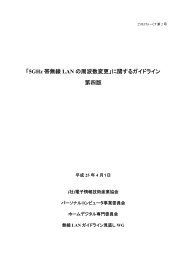
3.3.3 Method III (Bending <strong>test</strong>)<br />
a) Procedure for devices with lead wire terminals<br />
1) If its section modulus (in the least rigid direction) is less than or equal to that of a rectangular lead<br />
with a cross section of 0.15 mm x 0.5 mm or round leads < 0.5 mm in diameter, its leads shall be<br />
bent through an arc of at least 45° (Refer to (1) of Figure 2), measured at a distance 3 mm ± 0.5 mm<br />
along the lead from the component body unless otherwise specified.<br />
2) If its section modulus (in the least rigid direction) greater than that of a rectangular lead with a cross<br />
section of 0.15 mm x 0.5 mm or round leads greater than 0.5 mm in diameter, its leads shall be bent<br />
through an arc of a least 30° (Refer to (2) of Figure 2), measured at the lead extremities, unless<br />
otherwise specified.<br />
45°<br />
(1) Leads with small section modulus (2) Leads with large section modulus<br />
Figure 2 Bending <strong>test</strong> method for the lead wire terminal<br />
Remark: For rectangular strip terminations, the section modulus is given by the following formula:<br />
where<br />
Z x<br />
b × a<br />
=<br />
6<br />
2<br />
a is the thickness of the rectangular strip perpendicular to the bending axis.<br />
b is the other dimension of the rectangular strip.<br />
Zx is the section modulus.<br />
b) Procedure for devices with plate terminal I<br />
Leads shall be bent inward through an angle sufficient to cause the lead to retain a permanent bend<br />
(i.e. after stress removal) of at least 15°, measured at the lead extremities about the first bend (Refer to<br />
(1) of Figure 3). For packages that have the shoulder restrained (Refer to (2) of Figure 3), the angle of<br />
the bend shall be measured from the seating plane to the lead extremities. At the completion of the<br />
30°<br />
initial bend, the leads shall be returned to their approximate original position.
(1) (2)<br />
Figure 3 Bending <strong>test</strong> method for plate terminal I<br />
c) Procedure for devices with plate terminal II<br />
- 8 -<br />
<strong>EIAJ</strong> <strong>ED</strong>-<strong>4701</strong>/<strong>400</strong>-1<br />
Bend leads outward at 15°, then inward 30°, then returned to the original position (Refer to Figure 4).<br />
Figure 4 Bending <strong>test</strong> method for plate terminal II<br />
d) Procedure for devices with plate terminal III<br />
Carefully straighten the “J” bend portion using suitable jigs (fixture, tweezers etc.) (Refer to Figure 5).<br />
Then perform the following <strong>test</strong>s.<br />
Remark: Inspect each lead after straightening. Do not <strong>test</strong> any leads damaged by straightening<br />
Device<br />
15°<br />
operation.<br />
Lock fixture<br />
15°<br />
15°<br />
Lock nut<br />
30°<br />
Seating plane<br />
Test leads<br />
15°
) Procedure for devices with plate terminal I<br />
- 10 -<br />
<strong>EIAJ</strong> <strong>ED</strong>-<strong>4701</strong>/<strong>400</strong>-1<br />
Devices with plate terminal I shall be subjected to three cycles in accordance with 3.3.3 b).<br />
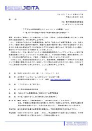
3.3.6 Method VI (Shear <strong>test</strong>)<br />
The width of the shear probe shall be about the width of the solder ball so it does not interfere with adjacent<br />
solder balls during the shear <strong>test</strong>. Align the probe so that it is 90°± 5° to the solder ball <strong>and</strong> moves parallel to<br />
the surface of the BGA module. The edge of the probe nearest the module surface sets between 1/4 the<br />
solder ball height <strong>and</strong> 0.05 mm on a substrate. Put the probe onto the side of solder ball in parallel, <strong>and</strong> load<br />
the ball at the rate of 300 μm/s ± 50 μm/s. Record the load <strong>and</strong> continue loading until the load reaches a<br />
maximum. Allow the loading to continue until the load falls to at least 3/4 of the maximum load before<br />
stopping. (Refer to Figure 8).<br />
3.4 Post treatment<br />
Figure 8 Shear <strong>test</strong> method of ball terminal<br />
Specified in the relevant specifications, when necessary.<br />
3.5 End-point measurement<br />
a) Method I, II, III, IV <strong>and</strong> V<br />
After finishing the <strong>test</strong>s, inspect the external visual with magnification of 10 to 20 times, <strong>and</strong> make sure<br />
that there is no cut, breakage <strong>and</strong> looseness. When there are specified items in the relevant<br />
specifications, carry out the measurements in conformity with the specified items <strong>and</strong> conditions.<br />
b) Method VI<br />
Solder ball<br />
L<strong>and</strong><br />
After finishing the <strong>test</strong>s, inspect the external visual with magnification of 10 to 20 times, <strong>and</strong> check the<br />
fracture mode of a solder ball junction part. Acceptable failure modes are: Mode A, Solder ball shear,<br />
<strong>and</strong> Mode B, Pad lifts. Unacceptable failure mode is Mode C, resulting from lack of solder wetting to<br />
the pad. Intermetallic failure, Mode D, can be allowed if the shear force meets with acceptable shear<br />
force in the relevant specifications. Priority is given to the result when satisfying junction intensity.<br />
When there are specified items in the relevant specifications, carry out the measurements in conformity<br />
with the specified items <strong>and</strong> conditions. Classifications of fracture mode in solder ball are as follows.<br />
(Refer to Table 2 <strong>and</strong> Figure 9).<br />
Shear probe<br />
0.05mm<br />
Solder resist<br />
1/4 the ball height<br />
Package surface
- 11 -<br />
<strong>EIAJ</strong> <strong>ED</strong>-<strong>4701</strong>/<strong>400</strong>-1
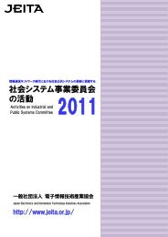
Table 2 Classifications of fracture mode<br />
Mode Note<br />
A Ball shear (concentrated fracture in the solder ball)<br />
B Pad lift (stripping between the l<strong>and</strong> <strong>and</strong> the board)<br />
C Ball lift (lack of solder wetting)<br />
D Intermetallic break<br />
Mode A Mode B Mode C Mode D<br />
Figure 9 Classifications of fracture mode<br />
4. Information to be given in the relevant specification<br />
- 12 -<br />
<strong>EIAJ</strong> <strong>ED</strong>-<strong>4701</strong>/<strong>400</strong>-1<br />
(1) Preliminary treatment (when required) [Refer to 3.1]<br />
(2) Items <strong>and</strong> conditions of the initial measurements (when required) [Refer to 3.2]<br />
(3) Types of <strong>test</strong> methods [Refer to 3.3]<br />
(4) Number of terminals to be <strong>test</strong>ed (cases other than the specified ones) [Refer to 3.3]<br />
(5) Pull force of the pull <strong>test</strong> (cases other than the specified ones) [Refer to 3.3.1]<br />
(6) Duration applied the pull force in the pull <strong>test</strong><br />
(cases other than the specified ones) [Refer to 3.3.1]<br />
(7) Torque, rotational position <strong>and</strong> rotational direction of the torsion <strong>test</strong><br />
(cases other than the specified ones) [Refer to 3.3.2]<br />
(8) Bending direction, bending angle <strong>and</strong> load of the bending <strong>test</strong><br />
(cases other than the specified ones) [Refer to 3.3.3]<br />
(9) Torque <strong>and</strong> torque duration of the screw terminal<br />
(cases other than the specified ones) [Refer to 3.3.4]<br />
(10) Number of cycles <strong>and</strong> load of the fatigue <strong>test</strong><br />
(cases other than the specified ones) [Refer to 3.3.5]<br />
(11) Fracture classification of the shear <strong>test</strong> (when required) [Refer to 3.3.6]<br />
(12) Post treatment (when required) [Refer to 3.4]<br />
(13) Items <strong>and</strong> conditions of the end-point measurement (when required) [Refer to 3.5]<br />
(14) Minimum shear fracture force [Refer to 3.5 b)]<br />
(15) Combination of judgment st<strong>and</strong>ards <strong>and</strong> fracture classification<br />
(when required) [Refer to 3.5 b)]
1. Remark<br />
- 13 -<br />
<strong>EIAJ</strong> <strong>ED</strong>-<strong>4701</strong>/<strong>400</strong>-1<br />
REFERENCE 1. SUPPLEMENTARY INFORMATION ON THE TEST METHOD<br />
Application to TCP (Tape carrier package): It is difficult to apply this st<strong>and</strong>ard to the lead terminals of TCP<br />
with extremely small cross-sectional areas comparing with conventional packages.<br />
2. For difference with another st<strong>and</strong>ard<br />
There is the following st<strong>and</strong>ard as another st<strong>and</strong>ard.<br />
a) For difference with IEC 60749-14<br />
IEC 60749-14 st<strong>and</strong>ard is almost same with this st<strong>and</strong>ard with all the <strong>test</strong> items <strong>and</strong> conditions except<br />
for the ball shear <strong>test</strong>.<br />
b) For difference with JIS C 0051 (IEC 60068-2-21)<br />
JIS st<strong>and</strong>ard (or IEC 60068-2-21) have the same <strong>test</strong> items as this st<strong>and</strong>ard. But, the <strong>test</strong> conditions<br />
are very different. Also, JIS st<strong>and</strong>ard have the terminal strength pushing <strong>test</strong> method that is not<br />
specified in this st<strong>and</strong>ard. There were not a proof of data <strong>and</strong> were as a future theme regarding this <strong>test</strong><br />
method.<br />
Also, there are st<strong>and</strong>ard applied to semiconductor surface mounting devices on board. It is specified as<br />
<strong>EIAJ</strong> <strong>ED</strong>-4702A “Mechanical stress <strong>test</strong> methods for semiconductor surface mounting devices” in<br />
<strong>JEITA</strong>.<br />
c) For difference with J<strong>ED</strong>EC JESD 22 B105-C<br />
J<strong>ED</strong>EC st<strong>and</strong>ard is almost same with this st<strong>and</strong>ard with all the <strong>test</strong> items <strong>and</strong> conditions except for the<br />
ball shear <strong>test</strong>.<br />
The <strong>test</strong> conditions have almost same content <strong>and</strong>, it supposed to refer from “MIL-STD-883E”.<br />
3. Purpose <strong>and</strong> process of the revision<br />
a) Harmony with IEC<br />
IEC 60068 st<strong>and</strong>ard was already presented in IEC st<strong>and</strong>ard as a general st<strong>and</strong>ard that was intended<br />
for electronic components. It had been used for not only electronic components but also semiconductor<br />
devices.<br />
Recently, IEC 60749-14 was established as the terminal strength <strong>test</strong> st<strong>and</strong>ards of the semiconductor<br />
device. Accordingly, this st<strong>and</strong>ard was reconsidered from a viewpoint of the harmony with IEC <strong>and</strong> was<br />
revised as follow.<br />
1) Significant revision of the <strong>test</strong> conditions for the conventional <strong>test</strong> items.<br />
2) Addition of the terminal fatigue <strong>test</strong> as method V.<br />
b) Response to the ball terminals<br />
While terminal strength measuring method for plate terminal, including QFP, has been provided, that<br />
for ball terminal (BGA, etc.) has yet to be done. Due to increasing general BGA packages, it is pressing<br />
need to provide a <strong>test</strong> method for those.<br />
Method VI (shear <strong>test</strong>) is provided after examination of terminal strength measuring method for ball<br />
terminal packages, such as BGA. This measuring method is applied also to bump terminal, such as FC.<br />
About the failure criteria after shear <strong>test</strong> in Method VI, there was also an opinion that it judges by<br />
fracture intensity. However, since it was difficult to decide a judgment value of fracture intensity, the<br />
judgment by fracture mode was adopted this time. In addition, in the case of the fracture mode A, the
guideline for the judgment value of fracture intensity is 15.0 N/mm 2 .<br />
- 14 -<br />
<strong>EIAJ</strong> <strong>ED</strong>-<strong>4701</strong>/<strong>400</strong>-1