Specification for Lifting Magnets (Third Revision)
Specification for Lifting Magnets (Third Revision)
Specification for Lifting Magnets (Third Revision)

You also want an ePaper? Increase the reach of your titles
YUMPU automatically turns print PDFs into web optimized ePapers that Google loves.
IPSS<br />
0. FOREWORD<br />
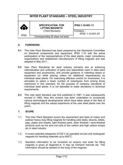
INTER PLANT STANDARD – STEEL INDUSTRY<br />
SPECIFICATION FOR<br />
LIFTING MAGNETS<br />
(<strong>Third</strong> <strong>Revision</strong>)<br />
Corresponding IS does not exist<br />
Page 1/10<br />
IPSS:1-10-001-11<br />
Formerly :<br />
IPSS: 1-10-001-07<br />
0.1 This Inter Plant Standard has been prepared by the Standards Committee<br />
on Electrical components and equipment, IPSS 1:10 with the active<br />
participation of the representatives of the steel plants, major consultancy<br />
organizations and established manufacturers of lifting magnets and was<br />
adopted in May 2011..<br />
0.2 Inter Plant Standards <strong>for</strong> steel industry primarily aim at achieving<br />
rationalization and unification of parts and assemblies used in steel plant<br />
equipment and accessories, and provide guidance in indenting stores or<br />
equipment (or while placing orders <strong>for</strong> additional requirements) by<br />
individual steel plants. For exercising effective control on inventories, it is<br />
advisable to select a fewer number of sizes/types from among those<br />
mentioned in this standard, <strong>for</strong> the purpose of company standards of<br />
individual steel plants. It is not desirable to make deviations in technical<br />
requirements.<br />
0.3 This inter plant standard was first published in 1981. It was subsequently<br />
revised in 1993. Now this revision has been undertaken to incorporate<br />
various technological developments which have taken place in the field of<br />
lifting magnets and the valued experience of the user steel plants over the<br />
years.<br />
1. SCOPE<br />
1.1 This Inter Plant Standard covers the requirement and tests of indoor and<br />
outdoor heavy duty lifting magnets <strong>for</strong> handling solid slabs, blooms, billets,<br />
pigs, plates and sheets, light finished parts, other finished / semi-finished<br />
products such as hot wire rod coils of low carbon and high carbon scraps<br />
etc in steel industry.<br />
1.2 It covers selected categories of 220 V dc operated circular and rectangular<br />
magnets <strong>for</strong> handling materials up to 600 o C.<br />
1.3 Standard in<strong>for</strong>mation to be furnished on enquiry and order <strong>for</strong> lifting<br />
magnets is given at Appendix-A. It may be hot/semi hot/cold etc. This<br />
in<strong>for</strong>mation should be welded on the body of the magnets.
IPSS:1-10-001-11<br />
1.4 Control panel <strong>for</strong> lifting magnet and the battery back-up unit & dc power<br />
pack <strong>for</strong> lifting magnets is separately envisaged in IPSS :1-04-037-99<br />
‘Magnet panel <strong>for</strong> cranes.’<br />
2. TERMINOLOGY<br />
2.1 For the purpose of this standard, the definitions contained in IS 1885<br />
(Part-1):1961 “Electrotechnical vocabulary: Part 1 Fundamental<br />
definitions” and IS 1885 (Part-31) :1971 “Electrotechnical vocabulary: Part<br />
31 Magnetism” shall apply.<br />
3. SITE CONDITIONS<br />
3.1 The following shall constitute the normal site conditions <strong>for</strong> the purpose of<br />
this standard:<br />
3.1.1 Location – The per<strong>for</strong>mance of magnets shall not be adversely influenced<br />
by the location having water, fumes, oil, steam etc, wherever mentioned.<br />
3.1.2 Ambient temperature - The normal ambient temperature shall be 50 o C or<br />
45 o C unless specified by the purchaser.<br />
3.1.3 Altitude - The altitude shall not exceed 1000m above sea level.<br />
3.1.4 Relative humidity - The maximum relative humidity shall be 100%.<br />
However, maximum temperature and maximum relative humidity may not<br />
occur simultaneously.<br />
3.1.5 Ambient air - The ambient air may contain a fair amount of conductive and<br />
corrosive metallic laden dust. The equipment to withstand saline<br />
atmospheric conditions.<br />
3.1.6 For special applications where steam and corrosive fumes are present,<br />
details shall be as agreed to between the manufacturer and the purchaser.<br />
4. SEALING<br />
4.1 The magnets shall be Hermetically sealed.<br />
5. RATING<br />
5.1 Working voltage – Rated lifting capacity of magnet shall be with the<br />
working voltage of 220 V dc subject to variation of +10%.<br />
5.2 <strong>Lifting</strong> capacity – The rated lifting capacity of the circular and rectangular<br />
magnets shall be as given in Tables 1 and 2. All magnets shall be suitable<br />
<strong>for</strong> a cyclic duration factor of 50% or 75% on 10 minutes rating class as<br />
per purchaser’s requirement.<br />
Page 2/10
6. DIMENSIONS<br />
IPSS:1-10-001-11<br />
6.1 The preferred outside dimensions of the circular and rectangular magnets<br />
shall be as given in Table 1 and 2.<br />
NOTE:The capacities and dimensions of the magnets specified in this standard are<br />
based on the assumption that copper conductors have been used <strong>for</strong> the coil windings.<br />
7. DISCHARGING THE MAGNET<br />
7.1 All magnets shall be provided with non-linear type discharge device of<br />
rating adequate to suppress all transient voltages. The discharge device<br />
shall be so located inside the terminal box that it could be replaced easily.<br />
8. DESIGN AND CONSTRUCTION<br />
8.1 Coils<br />
8.1.1 The conductor material shall be of copper strips, con<strong>for</strong>ming to IS<br />
1897:1983 `Copper strip <strong>for</strong> electrical purposes (second revision)<br />
(superseding IS 3285)’ and shall be free from burrs and will not have more<br />
than two joints in any single coil/cake. The joints shall be lap jointed and<br />
brazed all round. There shall be no joint in the portion of the coil<br />
immediately connecting to the leads <strong>for</strong> at least five turns. The last lap of<br />
the coil shall be rein<strong>for</strong>ced with a phospher-bronze strip.<br />
The coils shall be in the <strong>for</strong>m of cakes. The insulation provided between<br />
the coil cakes shall be of class H. Provision of RTDs may be considered<br />
NOTE: Rectangular copper conductor shall be covered with double layer varnish bonded<br />
glass-fibre, lapped firmly, evenly, closely and continuously around the conductor.These<br />
should con<strong>for</strong>m to IS 13730 (Part 0/sec 5) : 2003 The construction and other test<br />
parameters shall generally be in line with IS 4685:1968(Part-1) `Varnish bonded glassfibre<br />
covered copper conductors :(Part-1) Round wires’.<br />
8.1.2 The coils shall be suitably insulated with ceramic tape as turn to turn. For<br />
layer insulation between the cakes, mica insulation shall be used. Flexible<br />
micanite shall be used <strong>for</strong> body insulation.<br />
8.1.3 All magnets shall have minimum class H insulation. The manufacturer<br />
shall use class C insulation <strong>for</strong> handling materials at temperatures higher<br />
than 300 o C.<br />
8.1.4 The annular space between the coil and the magnet body shall be filled<br />
with silicon based compound. The filling compound shall be nonhygroscopic<br />
and shall have low co-efficient of thermal expansion and high<br />
thermal conductivity. It shall be able to withstand the rise in temperature<br />
corresponding to the class of insulation and shall be easily removable<br />
during the repair of the magnets.<br />
Page 3/10
IPSS:1-10-001-11<br />
8.1.5 The leads shall be firmly secured on to terminals inside the coil assembly<br />
and shall be protected from moisture and dust. The leads shall be brought<br />
out on the outer part of the coil so that it is safe from fracture caused by<br />
expansion/contraction of coil. Leads should be distinctly marked indicating<br />
the starting and ending winding.<br />
8.1.6 Ceramic sheets of adequate thickness to be provided in between the coil<br />
and bumping plate <strong>for</strong> hot application magnets (<strong>for</strong> above 300 degree C)..<br />
8.2 Magnet Body – Magnet body shall be cast from high permeability steel<br />
con<strong>for</strong>ming to Grade 2 of IS 4491:1994 `Steel casting <strong>for</strong> high magnetic<br />
permeability (third revision)’. The suspension lugs which are attached shall<br />
be cast integral with the magnet body.or any equivalent material mutually<br />
agreed between the purchaser and the supplier. In case of rectangular<br />
magnets, fabricated design may be adopted, using steel of grade Fe<br />
410WC according to IS 2062:2006 `Steel <strong>for</strong> general structural purposes –<br />
<strong>Specification</strong> (fifth revision) (superseding IS 226)’.<br />
8.2.1 The periphery of the shell shall be heavily ribbed to give added<br />
mechanical strength and increased radiation surface.<br />
8.2.2 The lifting magnet shall be supplied along with suitable chain sling<br />
con<strong>for</strong>ming to IPSS:1-07-038-96 `<strong>Specification</strong> <strong>for</strong> alloy steel chain sling<br />
(first revision)’.<br />
8.3 <strong>Magnets</strong> Poles – Outer poles must be integral part of the magnet. Inner<br />
poles shall preferably be integral part <strong>for</strong> circular magnet. However in case<br />
of bolted design, inner pole shall be fixed on to the magnet body with<br />
adequate number of bolts of minimum 19 mm dia. The heads of the bolts<br />
should be countersunk into the bodies of the poles and suitably locked.<br />
8.4 Bumping plate – For hot magnets double bumping plate of high<br />
mangenese non magnetic alloy con<strong>for</strong>ming to Grade ¼ of IS 276:2000<br />
`Austenitic – Manganese steel castings – specification (fifth revision)’<br />
shall be provided at the bottom <strong>for</strong> circular magnets to protect the coil from<br />
shock. For rectangular magnets, non-magnetic stainless steel or nonmagnetic<br />
mangenese steel bumping plate of adequate strength shall be<br />
provided at the bottom to protect the coil from shock.<br />
8.5 Bolts – High tensile steel bolts shall be used wherever necessary in the<br />
magnet construction.<br />
8.6 Terminals and Terminal Box – Each magnet shall have two terminals<br />
securely placed in the terminal box, which shall be capable of<br />
accommodating continuous duty copper cables. The terminal box shall be<br />
so located to prevent damages while loading hitting and shall be of three<br />
compartment type. The coil leads shall terminate in first compartment<br />
through insulated bushings. The terminal studs in the second<br />
Page 4/10
IPSS:1-10-001-11<br />
compartment shall be connected permanently to the termination points of<br />
the first compartment. The third compartment shall house the non-linear<br />
discharge resistor. The external feeding cables shall be connected to the<br />
terminal studs of the second compartment by the user. The terminal box<br />
shall be suitably enclosed to make it either water, steam, fume and oil<br />
proof or water tight or water resistant. Suitable provision <strong>for</strong> earthing shall<br />
be made. An additional identical terminal box with separate set of leads<br />
from the winding shall be provided as per mutual agreement between the<br />
purchaser and the supplier. One terminal box may be allowed in case of<br />
smaller and rectangular magnets. The enclosure protection class of the<br />
Terminal Box should be defined like IP-55<br />
8.7 External leads - A one meter long 3 core flexible EPR/CSP copper cable<br />
of suitable cross-section shall be connected through a water tight gland. A<br />
suitable plug-socket shall be provided.<br />
8.8 Clamping – Suitable clamping arrangement shall be made near the<br />
terminal box of the magnet to hold the feeding cable firmly against jerks or<br />
vibration and also to prevent any pull of the leads.<br />
9. TESTS<br />
9.1 Stage inspection – After the coil is placed and be<strong>for</strong>e filling of compound,<br />
the party should call <strong>for</strong> stage inspection.<br />
9.2 Each magnet shall be subjected to the following tests at the factory<br />
premises and shall be despatched with a test certificate :<br />
9.2.1 Type Test<br />
a) The manufacturer shall per<strong>for</strong>m load test on a representative<br />
sample of each lot or batch of each type/size/model of the lifting<br />
magnet <strong>for</strong> the 125% rated lifting capacity of the magnet in<br />
accordance with clause 5.2.<br />
b) User shall do selection of the magnet capacity considering service<br />
factor.<br />
9.2.2 Routine Test – The manufacturer shall per<strong>for</strong>m the following tests on<br />
each lifting magnet be<strong>for</strong>e despatch :<br />
a) Operating Current (cold) – The operating current under cold<br />
condition at rated voltage, shall not exceed the maximum values<br />
given in Table-1.<br />
Power Consumption : The ratio<br />
Power consumption (hot) in steady state condition<br />
Power consumption (cold) at the rated voltage<br />
should be > 0.7.<br />
Page 5/10
IPSS:1-10-001-11<br />
Note: Steady state condition – until 2 consecutive winding conditions are<br />
attained at half an hour interval.<br />
b) Temperature Rise Test – The magnet shall be subjected to repeated<br />
operations in cyclic duration factor (see clause 5.2) at rated voltage<br />
until steady state temperature condition of the winding is attained.<br />
c) High voltage test – The magnet shall withstand without breakdown<br />
in insulation when a high voltage of 2000 V ac at 50 Hz is applied<br />
between the coil and the body <strong>for</strong> one minute.<br />
d) Surge voltage test (with discharge device) – The surge voltage<br />
shall be tested with the help of an oscilloscope by breaking dc<br />
circuit. The maximum allowable surge voltage shall be 1600 V.<br />
e) Insulation Resistance Test<br />
i) The insulation resistance of the magnet coil shall be not less<br />
than 50 M-ohm when tested with a 1000 V direct reading<br />
portable insulation resistance tester in cold condition after<br />
the high voltage test, and<br />
ii) The insulation resistance shall be not less than 0.5 M-ohm<br />
after the steady state condition is attained.<br />
f) Flux density test – To be measured by Gauss Meter to substantiate<br />
the lifting capacity.<br />
10. MARKING<br />
10.1 Each magnet shall be provided with metallic name-plate giving the<br />
following in<strong>for</strong>mation :<br />
a) Type<br />
b) Manufacturer’s name, trade mark & serial No.<br />
c) Size of magnet<br />
d) <strong>Lifting</strong> capacity in kg (hot)<br />
e) Rated voltage<br />
f) Current (cold and hot)<br />
g) Weight of the magnet in kg<br />
h) Duty cycle<br />
i) Year of manufacture<br />
j) Class of insulation; and<br />
k) Reference to this standard i.e. IPSS:1-10-001-11<br />
10.2 Manufacturer’s trade mark, Sl No. and class of insulation shall be welded<br />
on the magnet body.<br />
Page 6/10
IPSS:1-10-001-11<br />
11. INFORMATION TO BE FURNISHED BY THE MANUFACTURER<br />
11.1 The manufacturer shall supply the following additional in<strong>for</strong>mation along<br />
with each lifting magnet:<br />
a) Coil winding data :<br />
i) Conductor material<br />
iii) Size of conductor<br />
iv) Number of turns<br />
v) Material of inter-turn insulation<br />
vi) Material of body insulation<br />
vii) Number of paths-series in parallel, and<br />
viii) Material of filling compound.<br />
b) Coil resistance – Cold & hot<br />
c) Power consumption – cold & hot<br />
d) Cross section drawing of magnet<br />
e) Detailed instruction <strong>for</strong> repair of magnet; and<br />
f) Test certificates (see clause 9)<br />
___________________<br />
Page 7/10
Size (dia) of<br />
Magnet in mm<br />
(+ 25 mm)<br />
IPSS:1-10-001-11<br />
TABLE – 1<br />
TECHNICAL PARAMETERS OF LIFTING MAGNETS<br />
(Clauses 5.2, 6, 9.1.2-a and 9.1.2-d)<br />
(A) Circular Magnet<br />
900 1150 1350 1600<br />
Cold current<br />
at 220 V dc<br />
and 40 o C,<br />
Max, A<br />
32.0 45.0 64.6 87.5<br />
Duty cycle, % 50 50 50 50<br />
Rated <strong>Lifting</strong> capacities in<br />
hot condition of magnet in (kg)<br />
Solid slabs 8000 16000 21500 31000<br />
Skull cracker<br />
balls (with<br />
normal pole<br />
shoes)<br />
4500 7000 8000 10000<br />
Sheet pressed<br />
and packed<br />
- - - 3000<br />
Heavy steel<br />
scraps<br />
300 700 1000 1800<br />
Pig iron<br />
castings<br />
300 700 1200 1800<br />
Light steel<br />
scraps<br />
250 400 550 800<br />
Size of<br />
Magnet in mm<br />
(+ 25 mm)<br />
Cold current<br />
at 220 V dc<br />
and 40 o C,<br />
Max, A<br />
900 mm x 600<br />
mm<br />
(B) Rectangular <strong>Magnets</strong><br />
1400 mm x<br />
600 mm<br />
14.5 22.0 27.4<br />
Page 8/10<br />
1700 mm x<br />
700 mm<br />
Duty cycle, % 50 50 50<br />
Rated <strong>Lifting</strong> capacities in<br />
hot condition of magnet in (kg)<br />
Solid slabs 8000 11000 14000<br />
Sheet pressed<br />
and packed<br />
2000 3200 5650<br />
Blooms - 7200 12800
IPSS:1-10-001-11<br />
TABLE – 2<br />
ADDITIONAL INFORMATION ON LIFTING CAPACITY OF<br />
ELECTROMAGNET (Clause 5.2 and 6)<br />
Type of material<br />
handling<br />
Size of material<br />
handling (mm)<br />
Page 9/10<br />
Number of<br />
magnets in<br />
operation<br />
Total lifting<br />
(kg)<br />
(A) Circular Magnet 1150 mm dia (+ 25 mm)<br />
a) Steel billet 60 x 60 x 8800 2 3400<br />
b) Steel billet 64 x 180 x 8800 2 3800<br />
c) Steel billet 50 x 50 x 8800 2 2500<br />
d) Steel sheet 60 x 2000 x 6000 1 5700<br />
e) Steel sheet 26 x 1250 x 7400 2 5800<br />
f) Steel sheet 8 x 1600 x 12000 4 6000<br />
g) Steel sheet 12 x 2500 x 12000 4 8500<br />
(B) Circular Magnet 1600 mm dia (+ 25 mm)<br />
a Bloom at 120 o C 90 x 110 x 230 1 2000<br />
b Pressed steel<br />
sheet packs<br />
- 1 2000<br />
c Rolls of steel at<br />
- 1 10000<br />
300 o C<br />
(C) Rectangular Magnet 900 mm x 600 mm (+ 25 mm)<br />
a Solid slab 20 x 1000 x 5000 1 8000<br />
b Solid slab 200 x 1065 x 4575 1 7745<br />
(D) Rectangular Magnet 1400 mm x 600 mm (+ 25 mm)<br />
a Steel sheet 14 x 1000 x 6000 1 1320<br />
b Steel sheet 200 x 1000 x 4000 1 3200<br />
c Blooms 450 x 450 x 4500 1 7200<br />
d Solid slab 300 x 1000 x 4500 1 11000<br />
(E) Rectangular Magnet 1700 mm x 700 mm (+ 25 mm)<br />
a) Solid slab 108 x 1010 x 4200 1 10800<br />
b) Solid slab 400 x 915 x 4500 1 14000<br />
c) Solid slab 112 x 760 x 4200 1 14000<br />
d) Blooms at 200 o C 300 x 300 x 4500 1 12800<br />
e) Blooms at 200 o C 270 x 270 x 4500 1 13500<br />
f) Rails P-50 at<br />
500 o C<br />
Length 2500 4 12500<br />
g) Rails P-65 at<br />
500 o C<br />
Length 2500 4 14600<br />
h) Rails P-75 at Length 2500 4 13000<br />
500 o C<br />
i) Sheets 7 x 1800 x 7000 2 7000<br />
j) Squares 65 x 65 x 6000 2 4200<br />
k) Steel billet 60 x 60 x 8800 2 3400<br />
l) Steel billet 64 x 180 x 8800 2 3800<br />
m) Steel billet 50 x 50 x 8800 2 2500
IPSS:1-10-001-11<br />
APPENDIX – A<br />
(clause 1.3)<br />
STANDARD INFORMATION FOR ENQUIRY AND ORDER<br />
FOR LIFTING MAGNETS<br />
1. a) Type of magnet : Circular / Rectangular<br />
b) Dimensions :<br />
2. Ambient temperature of working place :<br />
3. Working voltage<br />
4. Type of material to be handled<br />
5. a) Temperature of handling material (in o C)<br />
b) lifting weight of the material (in kg)<br />
6. Class of insulation of the magnet : H/C<br />
7. Duty cycle : 50% on 10 minutes<br />
or<br />
75% on 10 minutes<br />
8. Special conditions (if any).<br />
____________<br />
Page 10/10