Specification for Lifting Magnets (Third Revision)
Specification for Lifting Magnets (Third Revision)
Specification for Lifting Magnets (Third Revision)

Create successful ePaper yourself
Turn your PDF publications into a flip-book with our unique Google optimized e-Paper software.
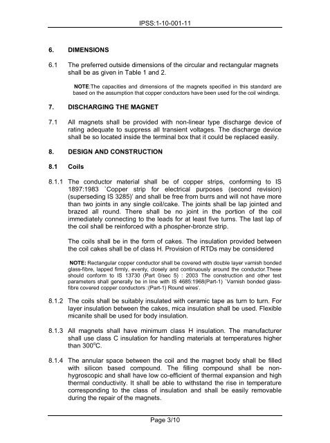
6. DIMENSIONS<br />
IPSS:1-10-001-11<br />
6.1 The preferred outside dimensions of the circular and rectangular magnets<br />
shall be as given in Table 1 and 2.<br />
NOTE:The capacities and dimensions of the magnets specified in this standard are<br />
based on the assumption that copper conductors have been used <strong>for</strong> the coil windings.<br />
7. DISCHARGING THE MAGNET<br />
7.1 All magnets shall be provided with non-linear type discharge device of<br />
rating adequate to suppress all transient voltages. The discharge device<br />
shall be so located inside the terminal box that it could be replaced easily.<br />
8. DESIGN AND CONSTRUCTION<br />
8.1 Coils<br />
8.1.1 The conductor material shall be of copper strips, con<strong>for</strong>ming to IS<br />
1897:1983 `Copper strip <strong>for</strong> electrical purposes (second revision)<br />
(superseding IS 3285)’ and shall be free from burrs and will not have more<br />
than two joints in any single coil/cake. The joints shall be lap jointed and<br />
brazed all round. There shall be no joint in the portion of the coil<br />
immediately connecting to the leads <strong>for</strong> at least five turns. The last lap of<br />
the coil shall be rein<strong>for</strong>ced with a phospher-bronze strip.<br />
The coils shall be in the <strong>for</strong>m of cakes. The insulation provided between<br />
the coil cakes shall be of class H. Provision of RTDs may be considered<br />
NOTE: Rectangular copper conductor shall be covered with double layer varnish bonded<br />
glass-fibre, lapped firmly, evenly, closely and continuously around the conductor.These<br />
should con<strong>for</strong>m to IS 13730 (Part 0/sec 5) : 2003 The construction and other test<br />
parameters shall generally be in line with IS 4685:1968(Part-1) `Varnish bonded glassfibre<br />
covered copper conductors :(Part-1) Round wires’.<br />
8.1.2 The coils shall be suitably insulated with ceramic tape as turn to turn. For<br />
layer insulation between the cakes, mica insulation shall be used. Flexible<br />
micanite shall be used <strong>for</strong> body insulation.<br />
8.1.3 All magnets shall have minimum class H insulation. The manufacturer<br />
shall use class C insulation <strong>for</strong> handling materials at temperatures higher<br />
than 300 o C.<br />
8.1.4 The annular space between the coil and the magnet body shall be filled<br />
with silicon based compound. The filling compound shall be nonhygroscopic<br />
and shall have low co-efficient of thermal expansion and high<br />
thermal conductivity. It shall be able to withstand the rise in temperature<br />
corresponding to the class of insulation and shall be easily removable<br />
during the repair of the magnets.<br />
Page 3/10