SPES 2020 Deliverable D1.2.A-1 Abstraction Layers
SPES 2020 Deliverable D1.2.A-1 Abstraction Layers
SPES 2020 Deliverable D1.2.A-1 Abstraction Layers

You also want an ePaper? Increase the reach of your titles
YUMPU automatically turns print PDFs into web optimized ePapers that Google loves.
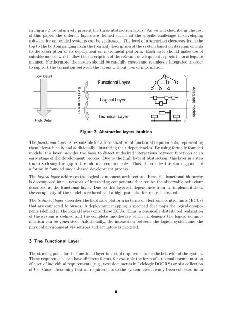
In Figure 2 we intuitively present the three abstraction layers. As we will describe in the rest<br />
of this paper, the different layers are defined such that the specific challenges in developing<br />
software for embedded systems can be addressed. The level of abstraction decreases from the<br />
top to the bottom ranging from the (partial) description of the system based on its requirements<br />
to the description of its deployment on a technical platform. Each layer should make use of<br />
suitable models which allow the description of the relevant development aspects in an adequate<br />
manner. Furthermore, the models should be carefully chosen and seamlessly integrated in order<br />
to support the transition between the layers without loss of information.<br />
Low Detail<br />
High Detail<br />
R e f i n e m e n t<br />
Functional Layer<br />
Logical Layer<br />
Technical Layer<br />
Figure 2: <strong>Abstraction</strong> layers intuition<br />
The functional layer is responsible for a formalization of functional requirements, representing<br />
them hierarchically and additionally illustrating their dependencies. By using formally founded<br />
models, this layer provides the basis to detect undesired interactions between functions at an<br />
early stage of the development process. Due to the high level of abstraction, this layer is a step<br />
towards closing the gap to the informal requirements. Thus, it provides the starting point of<br />
a formally founded model-based development process.<br />
The logical layer addresses the logical component architecture. Here, the functional hierarchy<br />
is decomposed into a network of interacting components that realize the observable behaviour<br />
described at the functional layer. Due to this layer’s independence from an implementation,<br />
the complexity of the model is reduced and a high potential for reuse is created.<br />
The technical layer describes the hardware platform in terms of electronic control units (ECUs)<br />
that are connected to busses. A deployment mapping is specified that maps the logical components<br />
(defined in the logical layer) onto these ECUs. Thus, a physically distributed realization<br />
of the system is defined and the complete middleware which implements the logical communication<br />
can be generated. Additionally, the interaction between the logical system and the<br />
physical environment via sensors and actuators is modeled.<br />
3 The Functional Layer<br />
The starting point for the functional layer is a set of requirements for the behavior of the system.<br />
These requirements can have different forms, for example the form of a textual documentation<br />
of a set of individual requirements (e. g., text documents in Telelogic DOORS) or of a collection<br />
of Use Cases. Assuming that all requirements to the system have already been collected in an<br />
6<br />
Adequate models