Tabor Electronics Ltd. - OED
Tabor Electronics Ltd. - OED
Tabor Electronics Ltd. - OED
You also want an ePaper? Increase the reach of your titles
YUMPU automatically turns print PDFs into web optimized ePapers that Google loves.
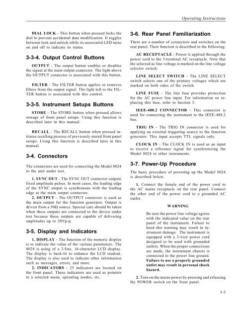
DIAL LOCK - This button when pressed locks the<br />
dial to prevent accidental data modification. It toggles<br />
between lock and unlock while its associated LED turns<br />
on and off to indicate its status.<br />
3-3-4. Output Control Buttons<br />
OUTPUT - The output button enables or disables<br />
the signal at the main output connector. The light above<br />
the OUTPUT connector is associated with this button.<br />
FILTER - The FILTER button applies or removes<br />
filters from the output signal. The light left to the FIL-<br />
TER button is associated with this control.<br />
3-3-5. Instrument Setups Buttons<br />
STORE - The STORE button when pressed allows<br />
storage of front panel setups. Using this function is<br />
described later in this manual.<br />
RECALL - The RECALL button when pressed initiates<br />
recalling process of previously stored front panel<br />
setups. Using this function is described later in this<br />
manual.<br />
3-4. Connectors<br />
The connectors are used for connecting the Model 8024<br />
to the unit under test.<br />
1. SYNC OUT - The SYNC OUT connector outputs<br />
fixed amplitude pulses. In most cases, the leading edge<br />
of the SYNC output is synchronous with the leading<br />
edge at the main output connector.<br />
2. OUTPUT - The OUTPUT connector is used as<br />
the main output for the function generator. Output is<br />
driven from a 50Ω source. Special care should be taken<br />
when these outputs are connected to the device under<br />
test because these outputs are capable of delivering<br />
amplitudes up to 20Vp-p.<br />
3-5. Display and Indicators<br />
1. DISPLAY - The function of the numeric display<br />
is to indicate the value of the various parameters. The<br />
8024 is using of a 2-line, 16-character LCD display.<br />
The display is back-lit to enhance the LCD readout.<br />
The display is also used to indicate other information<br />
such as messages, errors, and more.<br />
2. INDICATORS - 25 indicators are located on<br />
the front panel. These indicators are used as pointers<br />
to a selected menu, operating modes, etc.<br />
3-6. Rear Panel Familiarization<br />
There are a number of connectors and switches on the<br />
rear panel. Their function is described in the following.<br />
AC RECEPTACLE - Power is applied through the<br />
power cord to the 3-terminal AC receptacle. Note that<br />
the selected ac line voltage is marked on the line voltage<br />
selector switch.<br />
LINE SELECT SWITCH - The LINE SELECT<br />
switch selects one of the primary voltages which are<br />
marked on both sides of the switch.<br />
LINE FUSE - The line fuse provides protection<br />
for the AC power line input. For information on replacing<br />
this fuse, refer to Section 5.<br />
IEEE-488.2 CONNECTOR - This connector is<br />
used for connecting the instrument to the IEEE-488.2<br />
bus.<br />
TRIG IN - The TRIG IN connector is used for<br />
applying an external triggering source to the function<br />
generator. This input accepts TTL signals only.<br />
CLOCK IN - The CLOCK IN is used as an input<br />
to receive a reference signal for synchronizing the<br />
Model 8024 to other instruments.<br />
3-7. Power-Up Procedure<br />
The basic procedure of powering up the Model 8024<br />
is described below.<br />
1. Connect the female end of the power cord to<br />
the AC mains receptacle on the rear panel. Connect<br />
the other end of the power cord to a grounded AC<br />
outlet.<br />
WARNING<br />
Operating Instructions<br />
Be sure the power line voltage agrees<br />
with the indicated value on the rear<br />
panel of the instrument. Failure to<br />
heed this warning may result in instrument<br />
damage. The instrument is<br />
equipped with a 3-wire power cord<br />
designed to be used with grounded<br />
outlets. When the proper connections<br />
are made, the instrument chassis is<br />
connected to the power line ground.<br />
Failure to use a properly grounded<br />
outlet may result in personal shock<br />
hazard.<br />
2. Turn on the mains power by pressing and releasing<br />
the POWER switch on the front panel.<br />
3-3


