EET 270 Quiz 3 Chapters 7-10 Study Guide Semi-Automatic Motor ...
EET 270 Quiz 3 Chapters 7-10 Study Guide Semi-Automatic Motor ...
EET 270 Quiz 3 Chapters 7-10 Study Guide Semi-Automatic Motor ...

You also want an ePaper? Increase the reach of your titles
YUMPU automatically turns print PDFs into web optimized ePapers that Google loves.
<strong>EET</strong> <strong>270</strong> <strong>Quiz</strong> 3 <strong>Chapters</strong> 7-<strong>10</strong> <strong>Study</strong> <strong>Guide</strong><br />
<strong>Semi</strong>-<strong>Automatic</strong> <strong>Motor</strong> Starters, Multi-PB Stations, Wiring Diagrams, F/R Control, Inch and Jog<br />
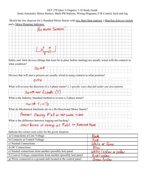
Sketch the line diagram for a Standard <strong>Motor</strong> Starter with two Start-Stop stations, a Run/Jog Selector switch<br />
and a <strong>Motor</strong> Running Indicator.<br />
Safety and limit devices (things that must be in place before starting) are usually wired with the contacts in<br />
what condition?<br />
Devices that will start a process are usually wired in using contacts in what position?<br />
What will reverse the direction of a 3-phase motor? ( 3 specific ways that fall under one description)<br />
What is the Industry Standard method to reverse a 3-phase motor?<br />
What do Mechanical Interlocks do on a Bi-Directional <strong>Motor</strong> Starter?<br />
What is the difference between Jogging and Inching?<br />
Indicate the correct wire color for the given situation.<br />
a) Connections at Line Voltage<br />
b) Connects at Control Voltage<br />
c) Neutral Connections<br />
d) DC Connections<br />
e) Neutral connections from another (possibly hot) panel<br />
f) Control-Voltage connections from another (possibly hot) panel<br />
g) Wires connected to a ground-stab located at the control panel
<strong>EET</strong> <strong>270</strong> <strong>Quiz</strong> 3 <strong>Chapters</strong> 7-<strong>10</strong> <strong>Study</strong> <strong>Guide</strong><br />
<strong>Semi</strong>-<strong>Automatic</strong> <strong>Motor</strong> Starters, Multi-PB Stations, Wiring Diagrams, F/R Control, Inch and Jog<br />
You have a control circuit that will operate 15 coils and 3 Solenoids. Each coil is rated to draw ½ amp when<br />
pulling in, the solenoids are rated to draw 1 Amp when pulling in. If the Control Voltage is 120V, what is the<br />
minimum KVA Transformer you can use?<br />
a) Why would it be a good idea to size-up the transformer a bit?<br />
Show how the transformers below would be connected for 120V on the secondary.<br />
What does it mean to “plug” a motor?
<strong>EET</strong> <strong>270</strong> <strong>Quiz</strong> 3 <strong>Chapters</strong> 7-<strong>10</strong> <strong>Study</strong> <strong>Guide</strong><br />
<strong>Semi</strong>-<strong>Automatic</strong> <strong>Motor</strong> Starters, Multi-PB Stations, Wiring Diagrams, F/R Control, Inch and Jog<br />
Lab) Sketch and build a Forward/Reverse <strong>Motor</strong> Starter with forward and reverse indictors; switch, contact and<br />
mechanical interlocks; and a three-phase motor. Include the following:<br />
____Power section with Circuit Breaker, 3-Phase Disconnect, F and R contacts, OL Heaters and <strong>Motor</strong><br />
____Control Transformer<br />
____Red Control-Power-on Light (R1)<br />
____E-Stop Relay Circuit (E-Stop, Main Start (Sealed-in), Control Relay and Green-Relay Coil Energized<br />
Indicator (G1))<br />
____F/R <strong>Motor</strong> Starter with Green-Forward Light (G2) and Red-Reverse Light (R2). Recall that a Forward/<br />
Reverse circuit has a NC Stop Switch, then, the forward direction will have A NC Reverse PB contact followed<br />
by the NO Forward PB Contact (sealed in by the F Coil), a set of NC R-Coil Contacts followed by the F Coil<br />
and the OL contact to Neutral.<br />
<strong>Motor</strong>-over-line Diagram