Three-Phase Transformers One 3-phase or 3 single-phase?
Three-Phase Transformers One 3-phase or 3 single-phase?
Three-Phase Transformers One 3-phase or 3 single-phase?

You also want an ePaper? Increase the reach of your titles
YUMPU automatically turns print PDFs into web optimized ePapers that Google loves.
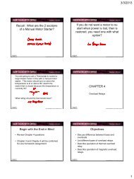
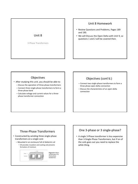
Unit 8<br />
3-<strong>Phase</strong> <strong>Transf<strong>or</strong>mers</strong><br />
Objectives<br />
• After studying this unit, you should be able to:<br />
– Discuss the operation of three-<strong>phase</strong> transf<strong>or</strong>mers<br />
– Connect three <strong>single</strong>-<strong>phase</strong> transf<strong>or</strong>mers to f<strong>or</strong>m a<br />
three-<strong>phase</strong> bank<br />
– Calculate voltage and current values f<strong>or</strong> a three<strong>phase</strong><br />
transf<strong>or</strong>mer connection<br />
<strong>Three</strong>-<strong>Phase</strong> <strong>Transf<strong>or</strong>mers</strong><br />
• Constructed by winding three <strong>single</strong>-<strong>phase</strong><br />
transf<strong>or</strong>mers on a <strong>single</strong> c<strong>or</strong>e<br />
– Mounted in an enclosure full of dielectric oil<br />
• Oil provides insulation and cooling and prevents<br />
f<strong>or</strong>mation of moisture<br />
Figure 8-1 Basic<br />
construction of a<br />
three-<strong>phase</strong><br />
transf<strong>or</strong>mer.<br />
Unit 8 Homew<strong>or</strong>k<br />
• Review Questions and Problems, Pages 189<br />
and 190.<br />
• We will Discuss the Open Delta with Unit 9, so<br />
questions 1 and 2 will be covered then.<br />
Objectives (cont'd.)<br />
– Connect two <strong>single</strong>-<strong>phase</strong> transf<strong>or</strong>mers to f<strong>or</strong>m a<br />
three-<strong>phase</strong> open-delta connection<br />
– Discuss the characteristics of an open-delta<br />
connection<br />
<strong>One</strong> 3-<strong>phase</strong> <strong>or</strong> 3 <strong>single</strong>-<strong>phase</strong>?<br />
• A <strong>single</strong> 3-<strong>Phase</strong> transf<strong>or</strong>mer is less expensive<br />
than 3-Single-<strong>Phase</strong> <strong>Transf<strong>or</strong>mers</strong>, but if on of<br />
the coils goes out you need to replace the<br />
while thing.<br />
2/22/2013<br />
1
Connecting Single-<strong>Phase</strong> <strong>Transf<strong>or</strong>mers</strong> in<br />
<strong>Three</strong>-<strong>Phase</strong> Bank<br />
• Using three <strong>single</strong>-<strong>phase</strong> transf<strong>or</strong>mers to make a<br />
three-<strong>phase</strong> bank:<br />
– Connect primary and secondary windings in wye <strong>or</strong><br />
delta<br />
– Label ends of each primary winding H 1 and H 2<br />
– Label ends of each secondary winding X 1 and X 2<br />
Figure 8-5 Identifying<br />
the windings.<br />
Figure 8-7 Connecting<br />
three <strong>single</strong>-<strong>phase</strong><br />
transf<strong>or</strong>mers to f<strong>or</strong>m a<br />
wye-delta three-<strong>phase</strong><br />
bank.<br />
<strong>Three</strong>-<strong>Phase</strong> Transf<strong>or</strong>mer Calculations<br />
• Follow f<strong>or</strong>mulas f<strong>or</strong> transf<strong>or</strong>mer and three<strong>phase</strong><br />
calculations when computing voltage and<br />
current f<strong>or</strong> three-<strong>phase</strong> transf<strong>or</strong>mers<br />
– Focus on the voltages and currents on the coils,<br />
which will be the “<strong>phase</strong> values,” then look at the<br />
voltages on the rest of the circuit.<br />
<strong>Three</strong>-<strong>Phase</strong> Transf<strong>or</strong>mer Connections<br />
• Wye-delta transf<strong>or</strong>mer has its primary winding<br />
connected in a wye and secondary connected in<br />
a delta<br />
• Delta-wye transf<strong>or</strong>mer has its primary winding<br />
connected in a delta and secondary connected<br />
in a wye<br />
<strong>One</strong>-line diagrams (Sh<strong>or</strong>thand)<br />
• <strong>One</strong>-line diagram: alternative method f<strong>or</strong><br />
illustrating three-<strong>phase</strong> transf<strong>or</strong>mer connections<br />
– Used to show main power distribution system of a<br />
large industrial plant<br />
Figure 8-8 <strong>One</strong>-line diagram symbol used to represent a deltawye<br />
three-<strong>phase</strong> transf<strong>or</strong>mer connection.<br />
Simple 3- <strong>Phase</strong> Connections<br />
Δ→Y (Delta Primary, Wye Secondary)<br />
2/22/2013<br />
2
Δ→Y Phas<strong>or</strong> Diagram Y→Y Connection<br />
Y→Y Phas<strong>or</strong> Diagram Special Note on Y-Y connections<br />
Stable Y→Y<br />
Y→Y stabilized by tying neutral together to the source-neutral<br />
• This is not a popular connection because if the<br />
currents in a Y-Y system are not balanced the<br />
<strong>phase</strong> voltages will not be stable. (We will see<br />
this in lab).<br />
• The only way to totally fix this is to tie the<br />
center of the Primary to the source Neutral<br />
and tie the secondary Neutral to the same<br />
point. This eliminates “Isolation.”<br />
Y→Δ Connections<br />
2/22/2013<br />
3
Y→Δ Phas<strong>or</strong> Diagram Special note about Power <strong>Transf<strong>or</strong>mers</strong><br />
• Power <strong>Transf<strong>or</strong>mers</strong> frequently have dualsecondaries.<br />
– This allows m<strong>or</strong>e options when connecting them.<br />
EET150 Chapter 4- Transf<strong>or</strong>mer Connection 20<br />
Pop Example: Connect a Δ→Y Δ →Δ Connection<br />
Δ →Δ <strong>Phase</strong> Diagrams Winding Markings<br />
After Manufacturing, the High Voltage Leads are<br />
labeled with “H” and the low Voltage with “X”<br />
2/22/2013<br />
4
Delta Connection, maintaining<br />
polarity<br />
Closing a Delta<br />
• Always check f<strong>or</strong> proper polarity bef<strong>or</strong>e making<br />
final connection and applying power<br />
– Test f<strong>or</strong> proper phasing with a voltmeter<br />
• If one <strong>phase</strong> winding is reversed, voltmeter will read<br />
double the applied voltage rather than 0 volts when<br />
applying power bef<strong>or</strong>e connection is closed<br />
• Test does not reveal whether reversed winding is in<br />
primary <strong>or</strong> secondary<br />
• Voltmeter may indicate voltage even if connection is<br />
c<strong>or</strong>rect (usually close to n<strong>or</strong>mal output voltage)<br />
T-Connected <strong>Transf<strong>or</strong>mers</strong><br />
• T-connection uses two transf<strong>or</strong>mers: main and<br />
teaser<br />
– Main transf<strong>or</strong>mer contains center <strong>or</strong> 50% tap f<strong>or</strong><br />
both primary and secondary windings<br />
– Teaser contains 86.6% voltage tap (preferred) f<strong>or</strong><br />
both primary and secondary<br />
• Connection can also be made with teaser with same<br />
voltage rating as main transf<strong>or</strong>mer, but teaser operates at<br />
reduced flux<br />
Delta Polarity notes<br />
• If you accidentally reverse the polarity of one<br />
of the windings in a Delta configuration you<br />
will severely unbalance the Secondary<br />
Voltages so always check the polarity bef<strong>or</strong>e<br />
closing the delta.<br />
(Always Check the fine print bef<strong>or</strong>e you seal the<br />
deal!)<br />
Closing the Delta<br />
When Closing the Delta a Δ primary to Δ secondary<br />
will usually give you 0 Volts out. A Y to Δ will read<br />
close to the output voltage, but if a coil is reversed it<br />
will read double the input voltage.<br />
T-Connected <strong>Transf<strong>or</strong>mers</strong> (cont'd.)<br />
– Main transf<strong>or</strong>mer connects directly across power<br />
line<br />
• <strong>One</strong> primary lead of teaser connects to center tap of<br />
main, 86.6% tap connects to power line, and same basic<br />
connection f<strong>or</strong> secondary leads<br />
– Advantage: T-connection maintains better <strong>phase</strong><br />
balance than open-delta<br />
– Disadvantage: one transf<strong>or</strong>mer must have a centertap<br />
on both the primary and secondary windings<br />
2/22/2013<br />
5
T Connection<br />
Figure 8-16 T-connected transf<strong>or</strong>mers.<br />
Scott Connection<br />
• Scott connection<br />
– Converts three-<strong>phase</strong> power into two-<strong>phase</strong> using<br />
two <strong>single</strong>-<strong>phase</strong> transf<strong>or</strong>mers<br />
• Main has 50% tap and teaser has 86.6% tap on primary,<br />
like T-connection, but secondary of each transf<strong>or</strong>mer<br />
provide <strong>phase</strong>s of two-<strong>phase</strong> system<br />
Scott Connection Application of Scott Connection<br />
Figure 8-19 Scott connection.<br />
M<strong>or</strong>al of the St<strong>or</strong>y:<br />
• You can use a Scott T to power larger 2-<strong>Phase</strong><br />
Loads without pulling your 3-<strong>Phase</strong> out of<br />
Balance<br />
Single-<strong>Phase</strong> Zone<br />
Heating/Blower<br />
units in a 3Φ<br />
system can be<br />
supplied using a<br />
Scott T.<br />
If the 2 units were<br />
run on 2 of the 3<br />
<strong>phase</strong>s, the 3Φ<br />
system would be<br />
unbalanced.<br />
Zig-Zag Connection<br />
• Zig-zag <strong>or</strong> interconnected-wye connection:<br />
– <strong>Three</strong>-<strong>phase</strong> autotransf<strong>or</strong>mer with windings<br />
divided into six equal parts<br />
2/22/2013<br />
6
Figure 8-21<br />
Schematic diagram of<br />
a zig-zag connection.<br />
Figure 8-20 Zig-zag<br />
connection.<br />
<strong>Three</strong>-<strong>Phase</strong> to Six-<strong>Phase</strong> Connections<br />
• Power system with m<strong>or</strong>e than three <strong>phase</strong>s:<br />
desirable f<strong>or</strong> converting AC to DC with minimal<br />
ripple.<br />
– Common example: diametrical connection<br />
• Requires only one low-voltage winding on each<br />
transf<strong>or</strong>mer<br />
• If center tapped, a neutral conduct<strong>or</strong> f<strong>or</strong> the six-<strong>phase</strong><br />
output permits half-wave rectification<br />
• High-voltage windings can be connected in wye <strong>or</strong> delta<br />
(preferred)<br />
Double-Delta Connection and Double-<br />
Wye Connection<br />
• Double-delta connection:<br />
– <strong>Transf<strong>or</strong>mers</strong> have two secondary windings that<br />
provide equal voltage, f<strong>or</strong>m two delta connections<br />
• Delta windings are reverse connected 180° out of<br />
<strong>phase</strong>; primary may be wye <strong>or</strong> delta<br />
Using a Zig-Zag Connection to get 3Φ<br />
with Neutral From a Grounded-Delta<br />
In this case I have a 480V<br />
Grounded-Delta system<br />
(one <strong>phase</strong> is grounded) and<br />
I want 277/480 f<strong>or</strong> lighting<br />
with a separate Neutral that<br />
is grounded. A 480/277V<br />
transf<strong>or</strong>mer could be used,<br />
but that would be a special<br />
size. This solution uses a<br />
common 480/240V<br />
Transf<strong>or</strong>mer connected Z-Z.<br />
A Zig-Zag Configuration can<br />
do that, while adding in<br />
Harmonic Suppression as a<br />
bonus.<br />
Figure 8-24 <strong>Three</strong> <strong>single</strong>-<strong>phase</strong><br />
center-tapped transf<strong>or</strong>mers are<br />
used to convert three-<strong>phase</strong> into<br />
six-<strong>phase</strong>.<br />
Figure 8-22<br />
Diametrical<br />
connection.<br />
Double-Delta Connection and Double-<br />
Wye Connection<br />
• Double-wye connection:<br />
– Like double-delta but secondary windings f<strong>or</strong>m<br />
two wyes<br />
• Windings are reverse connected 180°<br />
• Resembles diametrical connection with no center tap<br />
2/22/2013<br />
7
Figure 8-26 Schematic diagram<br />
of a double-delta connection with<br />
a wye-connected primary.<br />
Figure 8-25<br />
Double-delta<br />
connection.<br />
Problems 1 and 2<br />
Calculate the Primary Current (and a bunch of other<br />
stuff along the way)<br />
Solution sequence<br />
1) Use the Turns Ratio to figure out the secondary<br />
voltage (VP →N → VS)<br />
2) Use the Secondary Voltage to figure out the load<br />
current (VS →Z →ILoad)<br />
3) Use the Load Current to figure out the Secondary<br />
Current (ILoad →Configuration →ISecondary)<br />
4) Use the Secondary Current to figure out the Primary<br />
Current (ISecondary →N →IPrimary)<br />
Figure 8-28 Schematic<br />
diagram of a double-wye<br />
connection.<br />
Figure 8-27 Doublewye<br />
connection.<br />
Primary Current<br />
Bear in mind that with a transf<strong>or</strong>mer, the primary<br />
current is determined by the current drawn by the load.<br />
Example<br />
Let’s say that the Primary Voltage is 1380 V and the<br />
transf<strong>or</strong>mer N=6.63:1. What is the Primary Current and<br />
Transf<strong>or</strong>mer Power rating?<br />
2/22/2013<br />
8
V<br />
I<br />
I<br />
<strong>Phase</strong><br />
<strong>Phase</strong><br />
Example Detail 1<br />
First Detail: If the Transf<strong>or</strong>mer Primary winding is rated<br />
f<strong>or</strong> 1380V, and is connected in a Wye configuration,<br />
what are the <strong>Phase</strong> and Line Voltages?<br />
•Recall that the <strong>Phase</strong> voltage is the voltage across an element (like a<br />
Primary Coil) and the Line Voltage is the Voltage from “Line to Line.”<br />
E<br />
E<br />
E<br />
<strong>Phase</strong><br />
Line<br />
Line<br />
1380 V<br />
E<br />
<strong>Phase</strong><br />
2390 V<br />
3<br />
1380 V<br />
Example Solution Step 2<br />
Determine Load Current<br />
<strong>Phase</strong><br />
I<br />
I<br />
V<br />
208V<br />
3 3<br />
V<strong>Phase</strong><br />
120V<br />
Z 2.<br />
77<br />
I 43.<br />
3A<br />
Line<br />
Line<br />
120V<br />
43.<br />
3A<br />
Example Solution Step 4<br />
Determine Primary Currents<br />
Pr i <strong>Phase</strong><br />
Line<br />
I<br />
<strong>Phase</strong><br />
I<br />
Sec <strong>Phase</strong><br />
N<br />
3.<br />
77 A<br />
25A<br />
6.<br />
63<br />
3.<br />
77 A<br />
3<br />
2390 V<br />
Example Solution Step 1<br />
Determine Secondary Voltage<br />
V<br />
In a<br />
V<br />
Sec<br />
<strong>Phase</strong><br />
VPr<br />
i<br />
N<br />
1380V<br />
6.<br />
63<br />
208V<br />
configuration,<br />
V<br />
V<br />
Line<br />
208V<br />
<strong>Phase</strong><br />
V<br />
Line<br />
Example Solution Step 3<br />
Determine Secondary Current<br />
I<br />
<strong>Phase</strong><br />
I<br />
Line<br />
3<br />
43.<br />
3A<br />
3<br />
25AV<br />
Example Solution Step 5<br />
Determine Transf<strong>or</strong>mer Power<br />
Power ( VA)<br />
V<strong>Phase</strong>I<strong>Phase</strong><br />
1380<br />
V 3.<br />
77 A 5.<br />
2kVA<br />
Each<br />
2/22/2013<br />
9
Example Problem Summary<br />
• Given this circuit, the loads will receive 120V<br />
each IF EACH OF the transf<strong>or</strong>mers have a<br />
power rating of AT LEAST 5.2 kVA each.<br />
Summary (cont'd.)<br />
• Use <strong>phase</strong> values f<strong>or</strong> voltage and current<br />
when computing transf<strong>or</strong>mer values<br />
• Open-delta connects only two transf<strong>or</strong>mers<br />
• Two T-connected transf<strong>or</strong>mers can supply<br />
three-<strong>phase</strong> power<br />
• T-connection: main contains center tap,<br />
teaser ideally contains 86.6% voltage tap<br />
Summary<br />
• <strong>Three</strong>-<strong>phase</strong> transf<strong>or</strong>mers are constructed<br />
by winding three separate transf<strong>or</strong>mers on<br />
same c<strong>or</strong>e material<br />
• Single-<strong>phase</strong> transf<strong>or</strong>mers can be used as<br />
three-<strong>phase</strong> bank by connecting primary and<br />
secondary windings wye <strong>or</strong> delta<br />
• Follow three-<strong>phase</strong> circuit/transf<strong>or</strong>mer rules<br />
to compute three-<strong>phase</strong> transf<strong>or</strong>mer values<br />
Summary (cont'd.)<br />
• Scott connection converts three- to two<strong>phase</strong><br />
power<br />
• <strong>Three</strong>-<strong>phase</strong> transf<strong>or</strong>mers can connect to<br />
produce six-<strong>phase</strong> power<br />
• Double-delta and -wye require two<br />
secondary windings on each transf<strong>or</strong>mer<br />
without a center-tapped winding<br />
2/22/2013<br />
10