Experiments and Large Eddy Simulation of Underventilated Pool Fires
Experiments and Large Eddy Simulation of Underventilated Pool Fires
Experiments and Large Eddy Simulation of Underventilated Pool Fires

Create successful ePaper yourself
Turn your PDF publications into a flip-book with our unique Google optimized e-Paper software.
<strong>Experiments</strong> <strong>and</strong> <strong>Large</strong> <strong>Eddy</strong> <strong>Simulation</strong> <strong>of</strong> <strong>Underventilated</strong> <strong>Pool</strong> <strong>Fires</strong><br />
S. E. Yakush *1 , G. M. Makhviladze 2 , A.V. Chamchine 2 , P. Oleszczak 2<br />
1 A.Yu. Ishlinskii Institute for Problems in Mechanics, Moscow, Russia.<br />
2 University <strong>of</strong> Central Lancashire, Preston, UK<br />
Abstract<br />
Results <strong>of</strong> experimental <strong>and</strong> computational studies on the transient flame behavior in a compartment fire in the conditions<br />
<strong>of</strong> limited ventilation are presented. Hydrocarbon pool fires in a small-scale fire box with a single rectangular<br />
ventilation opening are considered. In the conditions where the oxygen supply into the compartment is insufficient<br />
to maintain steady combustion (underventilated fires), the flame becomes essentially transient <strong>and</strong> can be thrown out<br />
<strong>of</strong> the ventilation opening into the atmosphere. In the experiments, temperature-time curves as well as video recordings<br />
demonstrating the flame exhaust are obtained for four opening geometries. <strong>Large</strong> <strong>Eddy</strong> <strong>Simulation</strong>s (LES) <strong>of</strong><br />
underventilated fires are carried out <strong>and</strong> compared with the experiments.<br />
Introduction<br />
Flame behaviour in compartment fires has been a<br />
focus <strong>of</strong> numerous experimental <strong>and</strong> theoretical works.<br />
It is recognized that in the underventilated conditions,<br />
which are encountered when the oxygen supply is insufficient<br />
to maintain the required fuel burning rate, the<br />
flame becomes essentially transient. In some cases,<br />
flame extinction occurs, while a more dangerous scenario<br />
is when the flame reaches the ventilation opening<br />
<strong>and</strong> is thrown out into the atmosphere [1-3]. This leads<br />
to external flaming <strong>and</strong> can promote rapid fire spread<br />
over a multi-compartment building, or pose the danger<br />
<strong>of</strong> igniting nearby structures. To assess the fire spread<br />
hazards, it is important to know the relationship between<br />
the time from ignition to the flame exhaust, <strong>and</strong><br />
the fire source parameters, geometry <strong>of</strong> the compartment<br />
<strong>and</strong> openings, position <strong>of</strong> fire source etc.<br />
Flame exhaust in underventilated fires has mostly<br />
been studied experimentally <strong>and</strong> theoretically using the<br />
burner fire approach, when a gaseous fuel is supplied at<br />
a prescribed mass flowrate [4-6]. In real fires, however,<br />
the burning rate is not constant, but is controlled by the<br />
positive energy feedback from the flame to the fire bed.<br />
Thus, an important problem is to study the flame behavior<br />
in underventilated conditions for realistic fire<br />
sources.<br />
In this paper, recent experiments on transient pool fire<br />
development carried out in a small-scale fire box with a<br />
single rectangular opening are presented. Metal pans <strong>of</strong><br />
different size filled with liquid hydrocarbon fuels (petroleum<br />
ether) served as a fire source. Temperature<br />
measurements were carried out by several thermocouples<br />
to provide data on hot layer development <strong>and</strong><br />
flame emergence out <strong>of</strong> the ventilation opening. The<br />
main purpose <strong>of</strong> the work was to obtain the critical<br />
conditions for flame exhaust <strong>and</strong> to evaluate the induction<br />
time in different conditions. Also, numerical simulations<br />
<strong>of</strong> pool fire development in the conditions <strong>of</strong><br />
insufficient ventilations are carried out <strong>and</strong> compared<br />
with the experimental observations. *<br />
* Corresponding author: yakush@ipmnet.ru<br />
Proceedings <strong>of</strong> the European Combustion Meeting 2009<br />
Experimental Setup<br />
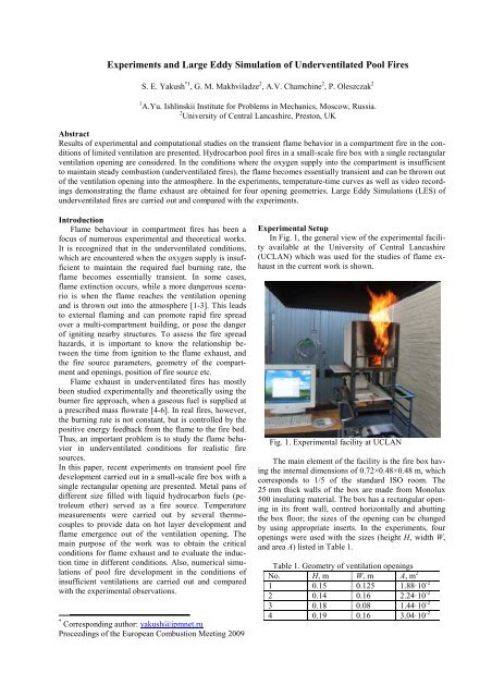
In Fig. 1, the general view <strong>of</strong> the experimental facility<br />
available at the University <strong>of</strong> Central Lancashire<br />
(UCLAN) which was used for the studies <strong>of</strong> flame exhaust<br />
in the current work is shown.<br />
Fig. 1. Experimental facility at UCLAN<br />
The main element <strong>of</strong> the facility is the fire box having<br />
the internal dimensions <strong>of</strong> 0.72×0.48×0.48 m, which<br />
corresponds to 1/5 <strong>of</strong> the st<strong>and</strong>ard ISO room. The<br />
25 mm thick walls <strong>of</strong> the box are made from Monolux<br />
500 insulating material. The box has a rectangular opening<br />
in its front wall, centred horizontally <strong>and</strong> abutting<br />
the box floor; the sizes <strong>of</strong> the opening can be changed<br />
by using appropriate inserts. In the experiments, four<br />
openings were used with the sizes (height H, width W,<br />
<strong>and</strong> area A) listed in Table 1.<br />
Table 1. Geometry <strong>of</strong> ventilation openings<br />
No. H, m W, m A, m 2<br />
1 0.15 0.125 1.88·10 -2<br />
2 0.14 0.16 2.24·10 -2<br />
3 0.18 0.08 1.44·10 -2<br />
4 0.19 0.16 3.04·10 -2
The box is equipped with a system <strong>of</strong> thermocouples<br />
located on side walls (14 thermocouples), ceiling (4<br />
thermocouples) <strong>and</strong> in the opening (4 thermocouples).<br />
Positions <strong>of</strong> the thermocouples are shown in Fig. 2. The<br />
thermocouple signals are collected in Thempscan-1100<br />
data logger <strong>and</strong> forwarded to an acquisition system<br />
installed on PC computer.<br />
Fig. 2. Positions <strong>of</strong> thermocouples in the firebox<br />
A square metal container was used as a fire source.<br />
Five sizes <strong>of</strong> the container were used in the tests, with<br />
the length <strong>of</strong> the container side equal to 60, 100, 120,<br />
150 <strong>and</strong> 200 mm. The height <strong>of</strong> the container walls was<br />
equal to 25 <strong>and</strong> 50 mm.<br />
Different kinds <strong>of</strong> liquid fuels were used in the studies:<br />
methanol, acetone, petrol, <strong>and</strong> petroleum ether.<br />
After some initial tests, petroleum ether was chosen for<br />
further research, since it gave more repeatable results.<br />
Some <strong>of</strong> the experiments with pool fires were repeated<br />
in the fire box with a glass side wall in order to visualize<br />
the fire development <strong>and</strong> flame exhaust process.<br />
Experimental Results<br />
In all the experiments on pool fires, the pan was<br />
filled with an initial volume <strong>of</strong> fuel equal to 100 ml. The<br />
fuel container was located at the centre <strong>of</strong> the fire box<br />
floor. Temperature records from all thermocouples were<br />
recorded, <strong>and</strong> the induction time (i.e., the time between<br />
the ignition <strong>and</strong> appearance <strong>of</strong> visible flame in the opening)<br />
was obtained from the temperature curves as well<br />
as from visual observations. Typically, it took between<br />
1.5 <strong>and</strong> 5 minutes for the flame exhaust to occur.<br />
In Fig. 3a the time histories <strong>of</strong> the ceiling temperatures<br />
obtained for opening 1 (see Table 1) are plotted for<br />
different pool sizes. In Fig. 3b, the temperature histories<br />
recorded by the top <strong>of</strong> the four thermocouples located in<br />
the opening are presented. The time to flame exhaust<br />
(induction period) is indicated by the peak on the opening<br />
temperature graph (the corresponding times for<br />
different pool sizes are denoted in Fig. 3 by vertical<br />
dashed lines). The dependence <strong>of</strong> the flame exhaust<br />
time on the pool size is shown in Fig. 4 for the two pan<br />
height, 25 <strong>and</strong> 50 mm.<br />
2<br />
T, [C]<br />
T, [C]<br />
500<br />
400<br />
300<br />
200<br />
100<br />
0<br />
0<br />
500<br />
50 100 150 200 250 300 350<br />
120 mm<br />
(b)<br />
400<br />
300<br />
200<br />
100<br />
120 mm<br />
150 mm<br />
150 mm<br />
100 mm<br />
(a)<br />
100 mm<br />
0<br />
0 50 100 150 200 250 300 350<br />
Time, [s]<br />
Fig. 3. Temperature histories for opening 1: (a) ceiling,<br />
(b) opening<br />
Flame exhaust time, [s]<br />
300<br />
250<br />
200<br />
150<br />
100<br />
Pan height<br />
25 mm<br />
50 mm<br />
100 120 140 160 180 200<br />
<strong>Pool</strong> Size, [mm]<br />
Fig. 4. Dependence <strong>of</strong> flame exhaust time on pool size<br />
for opening 1
For each experiment, the average mass loss rate was<br />
estimated; also, the specific mass loss rate (per unit area<br />
<strong>of</strong> the pool) was also determined. In Fig. 5a,b, these are<br />
plotted against the pool size. It can be seen that, with the<br />
increase in the pool size, the absolute mass loss rate<br />
grows, but not proportionately to the pool area: the<br />
specific mass loss rate decreases with the pool size,<br />
probably due to the decrease in the radiative feedback.<br />
Different depths <strong>of</strong> the pool could also result in different<br />
times necessary to heat the pan contents to boiling temperature,<br />
which could also contribute to the differences<br />
in the average specific evaporation rates.<br />
The experiments have shown that the smallest size<br />
<strong>of</strong> fuel pan required to obtain flame exhaust is equal to<br />
100 mm. It was observed that for a pan with side length<br />
<strong>of</strong> 200 mm <strong>and</strong> height <strong>of</strong> 50 mm there were strong oscillations<br />
<strong>of</strong> the flame <strong>and</strong> its extinction. However, for a<br />
container with height <strong>of</strong> 25 mm the flame exhaust was<br />
observed.<br />
The data in Figs. 4 <strong>and</strong> 5 demonstrate the typical degree<br />
<strong>of</strong> data scatter observed in the experiments performed<br />
for the same initial conditions. This is due to the<br />
intrinsic r<strong>and</strong>omness <strong>of</strong> the flame exhaust phenomenon.<br />
Similar results were obtained for other openings (see<br />
Table 1). In Figs. 6-8, the temperature curves under the<br />
ceiling <strong>and</strong> in the opening, as well as the flame exhaust<br />
times <strong>and</strong> mass loss rates (absolute <strong>and</strong> specific) obtained<br />
in the experiment with the largest opening 4 are<br />
presented.<br />
Mass loss rate, [g/s]<br />
Specific mass loss rate, [g/m 2 s]<br />
0.40<br />
0.35<br />
0.30<br />
0.25<br />
0.20<br />
0.15<br />
20<br />
18<br />
16<br />
14<br />
12<br />
10<br />
8<br />
6<br />
(a)<br />
100 120 140 160 180 200<br />
(b)<br />
Pan size<br />
25 mm<br />
50 mm<br />
100 120 140 160 180 200<br />
<strong>Pool</strong> size, [mm]<br />
Fig. 5. Dependence <strong>of</strong> absolute (a) <strong>and</strong> specific (b) mass<br />
loss rate for opening 1<br />
An interesting feature <strong>of</strong> the mass loss rate data is<br />
that for the smaller opening (Fig. 5), as well as for openings<br />
2 <strong>and</strong> 3, the absolute mass loss rate for the largest<br />
pan size (200 mm) turns out to be lower than for pan<br />
size <strong>of</strong> 150 mm. This was not observed in the experiments<br />
with opening 4 (Fig. 8), where the mass loss rate<br />
increased monotonically with the pan size. Also, for<br />
opening 4, no flame exhaust occurred for the fuel pan <strong>of</strong><br />
25 mm height, so only results for 50 mm high pan are<br />
plotted.<br />
3<br />
T, [C]<br />
T, [C]<br />
500<br />
400<br />
300<br />
200<br />
100<br />
0<br />
0<br />
600<br />
50 100 150 200 250 300 350<br />
500<br />
150 mm 120 mm (b)<br />
400<br />
300<br />
200<br />
100<br />
150 mm<br />
200 mm<br />
200 mm<br />
120 mm<br />
(a)<br />
100 mm<br />
100 mm<br />
0<br />
0 50 100 150 200 250 300 350<br />
Time, [s]<br />
Fig. 6. Temperature histories for opening 1: (a) ceiling,<br />
(b) opening<br />
Flame exhaust time, [s]<br />
250<br />
200<br />
150<br />
100<br />
Pan height<br />
50 mm<br />
100 120 140 160 180 200<br />
<strong>Pool</strong> size, [mm]<br />
Fig. 7. Dependence <strong>of</strong> flame exhaust time on pool size<br />
for opening 4
Mass loss rate, [g/s]<br />
Specific mass loss rate, [g/m 2 s]<br />
0.50<br />
0.45<br />
0.40<br />
0.35<br />
0.30<br />
0.25<br />
0.20<br />
30<br />
25<br />
20<br />
15<br />
10<br />
(a)<br />
100 120 140 160 180 200<br />
(b)<br />
Pan size<br />
50 mm<br />
100 120 140 160 180 200<br />
<strong>Pool</strong> size, [mm]<br />
Fig. 8. Dependence <strong>of</strong> absolute (a) <strong>and</strong> specific (b) mass<br />
loss rate for opening 4<br />
Thus, it can be seen that the flame exhaust time depends<br />
on ventilation opening geometry. The difference<br />
between the pool fires <strong>and</strong> burner fires is that in the<br />
latter case the fuel supply rate is a controlled parameter,<br />
whereas in the former case it depends on the feedback<br />
between the flame <strong>and</strong> fuel pool. It is interesting to see<br />
how the time to flame exhaust behaves as a function <strong>of</strong><br />
mass loss rate. Such a dependence, summarizing the<br />
results <strong>of</strong> all experiments performed, is presented in<br />
Fig. 9.<br />
Flame exhaust time, [s]<br />
350<br />
300<br />
250<br />
200<br />
150<br />
100<br />
50<br />
Opening Pan height<br />
1 50 mm<br />
2 50 mm<br />
3 50 mm<br />
4 50 mm<br />
1 25 mm<br />
2 25 mm<br />
3 25 mm<br />
0.2 0.3 0.4 0.5<br />
Mass loss rate, [g/s]<br />
Fig. 9. Summary <strong>of</strong> flame exhaust time dependence on<br />
mass loss rate in experiments with different openings<br />
<strong>and</strong> fuel pans<br />
Visualization <strong>of</strong> Flame Exhaust<br />
To reveal the features <strong>of</strong> transient flame development<br />
in undeventilated conditions, several experiments<br />
were carried out with one side wall <strong>of</strong> the fire box replaced<br />
by a glass wall (the remaining walls were made<br />
from Monolux 500, as in the previously described experiments).<br />
Also, the internal dimensions <strong>of</strong> the fire box<br />
<strong>and</strong> other experimental conditions (opening geometry,<br />
fuel source etc) remained the same.<br />
Due to its transparency, the glass wall increased the<br />
heat losses from the fire box, which affected the time to<br />
flame exhaust. For some combinations <strong>of</strong> the opening<br />
<strong>and</strong> pool sizes, it was even impossible to observe flaming<br />
in the opening. Nevertheless, there were found configurations<br />
where the results obtained in the glass box<br />
were very similar to those obtained in the Monolux box<br />
in terms <strong>of</strong> the flame exhaust times. For these configurations,<br />
video recording was carried out.<br />
In Fig. 10, six frames <strong>of</strong> such a video recording are<br />
presented. The configuration corresponds to the fuel pan<br />
size <strong>of</strong> 150 mm <strong>and</strong> ventilation opening 3 (see Table 1).<br />
Note that this opening is rather narrow <strong>and</strong> tall (width is<br />
8 cm <strong>and</strong> height is 18 cm) <strong>and</strong> has the smallest vent are<br />
<strong>of</strong> all openings studied. At the same time, the fuel pan is<br />
rather large. Therefore, oxygen starvation inside the box<br />
is reached early, <strong>and</strong> flame exhaust was reliably obtained<br />
in all experiments carried out for this configuration.<br />
Stronger oscillations <strong>of</strong> the flame were observed<br />
with fast ejection <strong>of</strong> the flame out <strong>of</strong> the box to distances<br />
up to 0.5 m from the box.<br />
Fig. 10. Snapshots <strong>of</strong> flame exhaust video recording for<br />
fuel pan size 150 mm <strong>and</strong> opening 3<br />
4
<strong>Large</strong> <strong>Eddy</strong> <strong>Simulation</strong>s<br />
Numerical modeling <strong>of</strong> underventilated pool fires<br />
was performed using Fire Dynamics Simulator (FDS),<br />
Version 5, developed at NIST, with the accompanying<br />
Smokeview viewer for visualization <strong>of</strong> results [7-9].<br />
Earlier, FDS was successfully applied to modelling <strong>of</strong><br />
underventilated burner fires [6]. In this work, the fire<br />
source was provided by evaporating liquid fuel, <strong>and</strong> the<br />
fuel supply rate is determined by the heat flux on the<br />
pool surface due to conduction <strong>and</strong> radiation. Thus, the<br />
evaporation rate cannot be set ad hoc, rather, it is determined<br />
in the course <strong>of</strong> the solution.<br />
The combustion model used in all LES simulations<br />
is that available in FDS by default <strong>and</strong> based on the<br />
mixture fraction approach in which a transport equation<br />
for the mixture fraction (defined to be 1 in the fuel <strong>and</strong> 0<br />
in the oxidizer) is solved [7, 8]. The state relations for<br />
the fuel (heptane was used to simulate the petroleum<br />
ether which is a mixture <strong>of</strong> several hydrocarbons) are<br />
applied to restore the species concentrations <strong>and</strong> assess<br />
the volumetric heat release rate. The reaction is assumed<br />
to proceed at an infinite rate, so that the fuel <strong>and</strong> oxidized<br />
cannot co-exist on both side <strong>of</strong> the surface where<br />
the mixture fraction corresponds to the stoichiometric<br />
conditions. It should be noted that, according to this<br />
model, the fuel ignites immediately upon entering the<br />
atmosphere, rather that after reaching the ignition<br />
source.<br />
The calculations have shown that simulations by<br />
FDS give adequate qualitative picture <strong>of</strong> the process, as<br />
was the case when burner fires were modeled previously<br />
[6]. However, quantitative characteristics <strong>of</strong> the process,<br />
most importantly, time to flame exhaust, are very sensitive<br />
to such parameters as absorption coefficient <strong>and</strong><br />
thermal properties <strong>of</strong> pool liquid, which are somewhat<br />
uncertain because petroleum ether is a mixture <strong>of</strong> several<br />
hydrocarbons. Also, convection in the burning pool is<br />
known to affect the burning rate, but is not taken into<br />
account in the FDS model. More detailed studies are<br />
required to assess the sensitivity <strong>of</strong> flame exhaust time<br />
to each parameter. In this paper, we present the results<br />
<strong>of</strong> preliminary calculations which demonstrate the predictive<br />
capabilities <strong>of</strong> LES model.<br />
In Figs. 11 <strong>and</strong> 12, the results obtained for the geometry<br />
<strong>of</strong> fire box used in the experiments described in<br />
the previous sections are presented. The opening was<br />
chosen to be 0.18 m high <strong>and</strong> 0.1 m wide, the fuel<br />
source was a square pan with the side <strong>of</strong> 150 mm.<br />
In Fig. 11, the distributions <strong>of</strong> volumetric heat release<br />
rate are presented (visualized by Smokeview<br />
viewer [9]) at four time instants, representing the main<br />
stages <strong>of</strong> the process: initial fuel-controlled combustion<br />
at t = 7 s, oxygen starvation <strong>and</strong> slumping <strong>of</strong> flame to<br />
the floor where oxygen is still available at t = 70 s,<br />
flame propagation towards the ventilation opening <strong>and</strong><br />
its emergence outside the fire box at t = 150 s, <strong>and</strong>,<br />
finally, developed external flaming at t = 240 s. The<br />
temperature fields in the plane <strong>of</strong> symmetry are shown<br />
at the same instants in Fig. 12. The time to flame exhaust<br />
obtained in the calculations (about 140 s) is <strong>of</strong> the<br />
same order as observed experimentally with the same<br />
pool size for openings 2 <strong>and</strong> 3, but more detailed comparison<br />
<strong>and</strong> analysis have yet to be done.<br />
Conclusions<br />
<strong>Experiments</strong> with underventilated pool fires have<br />
shown that the time to flame exhaust strongly depends<br />
on the size <strong>of</strong> the fuel source, compartment geometry<br />
<strong>and</strong> ventilation factor. The temperatures measured inside<br />
the box during the experiments were relatively low<br />
(in the range <strong>of</strong> 220÷310°C). The height <strong>of</strong> the fuel pan<br />
walls also affects the time to flame exhaust.<br />
In the pool fire experiments it was found that flame<br />
exhaust process is much more repeatable than in the<br />
burner fire experiments. It seems that pool fires are<br />
“self-organizing”: the fuel supply rate is controlled by<br />
the radiative feed from the flame. For the same fire box<br />
configuration, it results in more stable <strong>and</strong> repeatable<br />
flame development, at least in terms <strong>of</strong> flame exhaust.<br />
CFD modeling is capable <strong>of</strong> capturing the main features<br />
<strong>of</strong> underventilated pool fires, although detailed<br />
parametric study <strong>of</strong> coupled physical phenomena has<br />
yet to be done.<br />
Acknowledgments<br />
The research was supported by EPSRG (Grant No.<br />
GR/S69122/01) <strong>and</strong> Russian Science Support Foundation.<br />
References<br />
1. Bullen, M. L., <strong>and</strong> Thomas, P. H., Proc. Comb.<br />
Inst., 17: 1139-1148 (1978).<br />
2. Drysdale, D., An Introduction to Fire Dynamics<br />
(2 nd edition). Wiley, Chichester, UK, 1999.<br />
3. Chamberlain, G. A., Trans. IchemE, B, 72(B2):211-<br />
219 (1994).<br />
4. Sniegirev, A. Yu., Makhviladze, G. M., Talalov,<br />
V. A., <strong>and</strong> Chamchine, A. V., Combustion, Explosion<br />
<strong>and</strong> Shock Waves, 3(1):1-10 (2003).<br />
5. Sniegirev, A. Yu., Makhviladze, G. M., Talalov,<br />
V. A., Isaev, S. A., <strong>and</strong> Chamchine, A. V., Proc. 3 rd<br />
Conf. On Heat Transfer RNKT-3, Moscow, Russia,<br />
3: 227-230 (2002).<br />
6. Makhviladze, G. M., Shamshin, A. V., Yakush,<br />
S. E., <strong>and</strong> Zykov, A. P., Combustion, Explosion,<br />
<strong>and</strong> Shock Waves, 42(6):723-730 (2006).<br />
7. McGrattan, K., Hostikka, S., Floyd, J., Baum, H.,<br />
Rehm, R., Mell, W., McDermott, R., Fire Dynamics<br />
Simulator (Version 5): Technical Reference<br />
Guide. NIST Special Publication 1018-5 (2008 Edition);<br />
92 p. July 2008.<br />
8. McGrattan, K., Klein, B., Hostikka, S., <strong>and</strong><br />
Floyd, J., Fire Dynamics Simulator (Version 5):<br />
Users Guide. NIST Special Publication 1019-5<br />
(2008 Edition); 188 p. July 2008.<br />
9. Forney, G., User's Guide for Smokeview Version 5:<br />
A Tool for Visualizing Fire Dynamics <strong>Simulation</strong><br />
Data. NIST Special Publication 1017-5 (2008 Edition),<br />
142 p. July 2008.<br />
5
Fig. 11. <strong>Large</strong> eddy simulation <strong>of</strong> flame exhaust in underventilated<br />
pool fire: distributions <strong>of</strong> volumetric heat<br />
release rate are shown at t = 7,<br />
70, 150 <strong>and</strong> 240 s after<br />
ignition (top to bottom)<br />
Fig. 12. <strong>Large</strong> eddy simulation <strong>of</strong> flame exhaust in underventilated<br />
pool fire: temperature distributions in the<br />
central plane at t = 7,<br />
70, 150 <strong>and</strong> 240 s after ignition<br />
(top to bottom)<br />
6