AP2001 / AX2002
AP2001 / AX2002
AP2001 / AX2002

You also want an ePaper? Increase the reach of your titles
YUMPU automatically turns print PDFs into web optimized ePapers that Google loves.
<strong>AP2001</strong> / <strong>AX2002</strong><br />
Smart Power Supply / AEbus extender<br />
GENERAL<br />
Processor controlled power supply and AEbus extender base unit. Input 230 VAC or 24VDC, output<br />
27VDC/ 1.3A short circuit protected to supply several AEpacks. Optional fully monitored UPS<br />
functionality. Communication watcher and reset capabilities for abnormal situations.<br />
<strong>AX2002</strong> can be added in <strong>AP2001</strong> for extending AEbus to AEpacks at distance more than 5 meter (up<br />
to total bus length of 300 meters)<br />
CONNECTIONS<br />
AEbus extender<br />
(optional)<br />
AEbus<br />
Peripherals<br />
Supply IN<br />
AEpacks are hot-swappable, so changing AEpacks or connections can<br />
be done without interrupting the other AEpacks connected on the AEpu.<br />
All connections are underneath the covers of the AEpack. Topcover<br />
must be left in place, bottomcover can be lift off straight up.<br />
On top: Connections for AEbus<br />
On bottom: Connections to peripherials<br />
Remark: The <strong>AX2002</strong> is not hot-swappable, always disconnect power!<br />
AEbus CONNECTIONS<br />
AEbus connections: point to point to identical connector point of<br />
each AEpack. The AEbus connector has two rows, which enables<br />
easy coupling of more AEpacks.<br />
Going outside AEpacks housing: shielded cable must be used; CH<br />
and CL must be one twisted pair. From other pair one cable is<br />
used for GND. Shield must be connected to metal housing, to<br />
which also the metal mounting rail of the AEpacks is connected.<br />
AEpacks at larger distance use the AEbus extender (<strong>AX2002</strong>) on<br />
the power supply.<br />
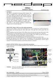
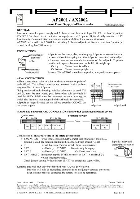
MAINS and PERIPHERAL CONNECTIONS and FUSES (underneath bottom cover)<br />
ALT mode button Schematic top view<br />
F2 1,6A SB F3 1,6A SB F1 3,15A SB<br />
IN1 GND<br />
BAT 1 BAT 1 BAT BAT 2 BAT 2<br />
230VAC 230VAC<br />
+ - + -<br />
L L N N<br />
Connections: (Take always care of the safety precautions)<br />
• 230VAC L/N Power input, connect GND to metal case of housing. If no metal<br />
housing is used, the mounting rail must be connected with ground (GND)<br />
• IN1: Default function: Tamper switch. Input is supervised<br />
• BAT 1 Lead battery 1: 12 VDC Batteries only for supply<br />
• BAT 2 Lead battery 2: 12 VDC of <strong>AP2001</strong>, max 1,3 A<br />
• BAT 1+BAT 2: Emergency supply 24VDC (connect to BAT 1+ and BAT 2-)<br />
Not for loading batteries.<br />
Check jumper setting for lead battery (BATT) or emergency supply (EM)<br />
Remark: Batteries may only be connected with <strong>AP2001</strong> power down.<br />
Batteries will only be recognized after power up and jumper settings are correct.<br />
Even with no batteries connected the battery test will be performed.<br />
Installation sheet<br />
Date 13 June 2006 Version 2<br />
Part.no.: 5260930<br />
This information is furnished for guidance, and with no guarantee as to its accuracy or completeness; its publication conveys no licence under any patent or<br />
other right, nor does the publisher assume liability for any consequence of its use; specifications and availability of goods mentioned in it are subject to change<br />
without notice; it is not to be reproduced in any way, in whole or in part, without the written consent of the publisher.<br />
Fuses<br />
VIN<br />
GND<br />
CH<br />
CL<br />
GND<br />
AEbus connectors<br />
rear view<br />
AEpack n AEpack n+1<br />
© Nedap N.V., IDEAS P.O. Box 103 NL-7140 AC GROENLO The Netherlands Page 1 of 4<br />
IN1<br />
GND<br />
R=4K7<br />
R= 4K7<br />
Contact<br />
®<br />
Input is supervised<br />
(software selectable)
<strong>AP2001</strong> / <strong>AX2002</strong><br />
SAFETY PRECAUTIONS GENERAL<br />
This equipment should be installed, operated, serviced, and repaired by qualified personnel only. The installation and<br />
interconnection of this equipment to facility wiring and other equipment must be done by a competent, qualified<br />
craftsperson who is familiar with applicable standards and codes governing the installation.<br />
Installation methods, practices, or procedures that are unauthorised or done improperly are dangerous and could result in<br />
serious personal injury or damage to property and equipment<br />
WARNING<br />
Power Supply: Ensure the source voltage matches the voltage of power supply before turning ON the power.<br />
Power Cord and Plug: To prevent an electric shock or fire, be sure to use the power cord as described below:<br />
Maximum 4.5 m (14.76 ft.) long. UL/CSA approved, rated minimum 250 V, 10 A, having a 3 x 18 AWG, Type SJT flexible<br />
cord. One end terminates with a parallel blade (120V units) or tandem blade (240V units) grounding, molded-on, attachment<br />
plug with a 10 A, 110/240 V NEMA 5-15P/NEMA 1-15P configuration.<br />
The socket-outlet shall be installed near the equipment and shall be easy accessible.<br />
Fixed Power Connection: In the case of a fixed connection to the mains a disconnect from mains must be available near the<br />
equipment.<br />
Protective Grounding: The protective grounding terminal must be connected to ground to prevent an electric shock before<br />
turning ON the power.<br />
Fuse: For continued protection against risk of fire replace fuses only with the same type and rating of fuse.<br />
Before replacing the fuses, turn off the power and disconnect the power source. Do not use a different fuse or short-circuit<br />
the fuse holder.<br />
Do Not Operate Near Flammable Materials: Do not operate the equipment in the presence of flammable liquids or<br />
vapours. Operation of any electrical equipment in such environment constitutes a safety hazard.<br />
Opening the covers: Do not open the top cover when active since lethal voltages do exist inside. Always first disconnect<br />
from mains supply and make sure maintenance is safe.<br />
Do Not Modify: To be sure of safety, do not modify or add anything to the equipment other than mentioned in this<br />
installation guide or indicated by NEDAP NV.<br />
Batteries: Under certain conditions storage batteries will expel explosive hydrogen gas. Do not allow smoking, welding or<br />
sparks in the vicinity of any storage battery. Adequate ventilation must be provided around batteries. Battery racks must also<br />
be grounded to minimise static charges.<br />
LED INDICATORS<br />
ADDR ERR(red)<br />
ON No AEpu connection (AEpack passive)<br />
Flashing 5 Hz No valid AEpack address (or already in use)<br />
Flashing 20 Hz AEpack address being modified<br />
BUS ERR (red)<br />
ON Bus error<br />
ADDRESS SWITCHES<br />
Turn for correct address<br />
JUMPERS<br />
EM Nothing or emergency supply connected<br />
BATT Lead battery connected<br />
POWER (green)<br />
ON Power present<br />
BATTERY STATUS<br />
BFL Battery empty or not present<br />
BOK Battery available and correct<br />
BAC Battery/Emergency active (in use)<br />
BLD Battery loading<br />
STATUS (blue)<br />
Slow blinking AEpack assigned to AEpu (operating)<br />
Very fast blinking ALT mode active<br />
Fast blinking Downloading or error during loading<br />
1 short flash AEpack not coupled<br />
2 short flashes Firmware present but not active<br />
3 short flashes No firmware present<br />
POWER OUTPUT STATUS<br />
OVL Power output overload<br />
POK Power output correct<br />
ADDRESS SETTING<br />
The Address switch gives address of AEpack. Left: units of 10, right: units of 1.<br />
BUS ERR and ADDR ERR LED’s indicates address status. At valid address both LED’s must be off.<br />
New installation: select free address, replacing AEpack: use the same address.<br />
The address is used for configuring the AEpack (software settings) so write it down.<br />
Address 00 is used to set the AEpack off-line.<br />
© Nedap N.V. <strong>AP2001</strong> / <strong>AX2002</strong> Installation sheet Page 2 of 4
<strong>AP2001</strong> / <strong>AX2002</strong><br />
JUMPER SETTINGS: Set both jumpers according to type emergency supply / battery connected.<br />
Only after power up the <strong>AP2001</strong> will recognize the jumper settings, and for BATT will only after<br />
power up load the connected batteries<br />
AEPACK LOCAL TEST (ALT MODE): 1: Battery active OFF, Battery load OFF; 2: Battery<br />
active ON, Battery load OFF; 3: Battery active OFF, Battery load OFF; 4: Battery active OFF, Battery<br />
load ON; 5: Battery active OFF, Battery load OFF; 6: Test Battery. (Tests will loop around)<br />
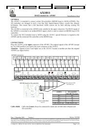
TYPICAL CONFIGURATION<br />
AEpacks can be connected to the <strong>AP2001</strong> (or AP2003) for supply of power and communication bus<br />
(extended AEbus). Also an AP8001 (AEpu) is needed for data handling and connection to AEserver.<br />
All AEpacks are connected to each other using the AEbus with the interlinking connector at the upper<br />
side of each AEpack.<br />
Ethernet<br />
to AEserver<br />
AEbus<br />
230 VAC<br />
5 meter<br />
Door and<br />
antenna<br />
Door and<br />
antenna<br />
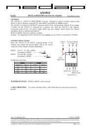
CALCULATION MODEL MAXIMUM POWERLOAD (see also www.nedap.net)<br />
More than one AEpack can be connected to the power AEpack. For the calculation of the total power<br />
consumption add the internal power<br />
consumption of each individual AEpack<br />
and the load it’s load from external devices<br />
(e.g. lock).<br />
With the diagram beside the total load for<br />
an <strong>AP2001</strong> can be calculated. If the total<br />
load exceeds the 1.3A (1.1A * ) an extra<br />
<strong>AP2001</strong> must be added.<br />
The used AEpacks are in italic. For the<br />
12VDC output a correction factor of 0,65<br />
is used to get the correct load for 27VDC<br />
(AEbus power).<br />
In this example total load is 2220mA, so<br />
two <strong>AP2001</strong>’s (AP2003’s) are needed.<br />
(* : for AP2003: at 110VAC max 1.1A)<br />
Extended AEbus<br />
300 meter<br />
230 VAC<br />
Door and<br />
antenna<br />
5 meter<br />
USING MORE THAN ONE POWER SUPPLY<br />
If more than one power AEpack is needed (and AEbus is not longer than 5 meters, otherwise <strong>AX2002</strong><br />
must be used), connect only CH, CL and GND signals to AEbus connector between the group of<br />
AEpacks belonging to a power AEpack. (don’t connect VIN and GND). CH and CL must be one<br />
twisted pair. From other pair one cable is used for GND.<br />
EXTENDED AEBUS: <strong>AX2002</strong> (optional)<br />
If the AEbus exceeds 5 meters, the <strong>AX2002</strong> board must be installed in the <strong>AP2001</strong> on both sides (see<br />
also above figure). The total length of the AEbus if <strong>AX2002</strong>’s are used is 300 meters. Installation of<br />
the <strong>AX2002</strong> will be at factory. In those case where the <strong>AX2002</strong> must be installed in the <strong>AP2001</strong><br />
always take care of the safety precautions.<br />
© Nedap N.V. <strong>AP2001</strong> / <strong>AX2002</strong> Installation sheet Page 3 of 4<br />
AEbus<br />
Example:<br />
Total 3 readers on one<br />
AEpu and 2 power<br />
supplies<br />
AEpack Internal Load on output (mA) Total load<br />
load (mA) 24VDC 12VDC (0.65x) (mA)<br />
AP1001 150 200 x 0,65 = 130 280<br />
AP1002 250<br />
AP1003 120 500 x 0,65 = 325 445<br />
AP1003 120 300 420<br />
AP1005 250<br />
AP1007 200<br />
AP1009 150<br />
AP3002 50 100 150<br />
AP3002<br />
AP3003<br />
50 250 300<br />
AP3004 125 200 325<br />
AP8001 300 300<br />
Total load on 27VDC (AEbus power) 2220
<strong>AP2001</strong> / <strong>AX2002</strong><br />
Attention: set switch at backside of the <strong>AX2002</strong> to the correct position: Switch selects terminating<br />
resistor needed for correct communication:<br />
First and last <strong>AX2002</strong> of the extended AEbus: switch to IN-side (towards connector)<br />
All other <strong>AX2002</strong>’s: switch to OUT-side<br />
Remark: <strong>AX2002</strong>’s must always be connected to other <strong>AX2002</strong>’s, so never to the AEbus connector.<br />
EXTENDED AEBUS CONNECTIONS (<strong>AX2002</strong>)<br />
The connector for the extended AEbus is<br />
located above the AEbus connector. Only the<br />
communication is extended, not the power<br />
supply (this is achieved from the Power AEpack<br />
on which the <strong>AX2002</strong> is installed).<br />
Using 2 x 2 x 0,50 mm² shielded cable means<br />
that CH and CL must be one twisted pair.<br />
From the other pair only one cable is connected<br />
to GND. The cable shield must be connected to<br />
the housing of the AEbox.<br />
SPECIFICATIONS <strong>AP2001</strong> (Product nr. 9835830)<br />
Dimensions: 230 x 126 x 70 mm (excluding mounting rail) Weight: ± 600 gr<br />
AEbus: AEbus communication and Power, Non isolated, Bitrate: high<br />
Output: AEbus power: 27 VDC, max 1,3 A at 230 VAC<br />
Environment: Temperature: Operating: 0 – 55 °C, Storage: -30 – 65 °C Relative humidity: 10 – 93% non condensing<br />
Power: 230 – 240 VAC (-10%+6%) 50/60 Hz, (max 0,42 Amp at 230 VAC)<br />
Safety: Class I<br />
Emergency supply: 22 – 30 VDC, max 1,5A (at 24 VDC) (SELV)<br />
Lead battery backup: Always 2 x 12 VDC / max 7Ah<br />
Max charge time: 24 hours (from 0% to 100% charge)<br />
Max load discharge time: 5 hours (from 100% to 0% charge)( max load 1,3 A)<br />
Inputs: 1: Intended for dry contact or open collector, optional supervised (software selectable)<br />
CABLE SPECIFICATIONS<br />
230 VAC Power: 3 x 0,75mm², due to local restrictions, must have earth connection<br />
AEbus: 5 x 0,5mm² shielded, max cable length: 5 meter in case power supplied (no additional power AEpack)<br />
2 x 2 x 0,5mm² shielded, max cable length: 5 meter in case no power supplied (additional power AEpack)<br />
Inputs: 2 x 0,25mm², max cable length: 100 meter, cable capacity