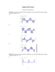
1 Short help on Parks-McClellan design of FIR Low Pass Filters ...
1 Short help on Parks-McClellan design of FIR Low Pass Filters ...
1 Short help on Parks-McClellan design of FIR Low Pass Filters ...

You also want an ePaper? Increase the reach of your titles
YUMPU automatically turns print PDFs into web optimized ePapers that Google loves.
Purdue University: ECE438 - Digital Signal Processing with Applicati<strong>on</strong>s 1<br />
1 <str<strong>on</strong>g>Short</str<strong>on</strong>g> <str<strong>on</strong>g>help</str<strong>on</strong>g> <strong>on</strong> <strong>Parks</strong>-<strong>McClellan</strong> <strong>design</strong> <strong>of</strong> <strong>FIR</strong> <strong>Low</strong><br />
<strong>Pass</strong> <strong>Filters</strong> using Matlab<br />
The <strong>design</strong> <strong>of</strong> an <strong>FIR</strong> filter using <strong>Parks</strong>-<strong>McClellan</strong> algorithm is a two-step process. First,<br />
you need to use the firpmord command to estimate the order <strong>of</strong> the optimal <strong>Parks</strong>-<strong>McClellan</strong><br />
<strong>FIR</strong> filter to meet your <strong>design</strong> specificati<strong>on</strong>s. The syntax <strong>of</strong> the command is as follows:<br />
[n,fo,mo,w]=firpmord(f,m,dev)<br />
f is the vector <strong>of</strong> band frequencies. For a low pass filter, f=[wp ws] where wp is the upper<br />
edge <strong>of</strong> the passband and ws is the lower edge <strong>of</strong> the stopband. The vector m c<strong>on</strong>tains the<br />
desired magnitude resp<strong>on</strong>se values at the passbands and the stopbands <strong>of</strong> the filter. Since<br />
a lowpass filter c<strong>on</strong>sists <strong>of</strong> a passband followed by a stopband, m has two entires. Namely,<br />
m=[1 0] because you would like the magnitude resp<strong>on</strong>se to be equal to 1 in the passband<br />
and equal to 0 in the stopband. The vector dev has the maximum allowable deviati<strong>on</strong>s <strong>of</strong><br />
the magnitude resp<strong>on</strong>se <strong>of</strong> the filter from the desired magnitude resp<strong>on</strong>se. It has the same<br />
number <strong>of</strong> entries as there are m. Thus, for a low-pass filter it has two entries and is equal<br />
to [passband ripple, stopband ripple]. After you specify the vectors f, m and dev, you<br />
can run the firpmord command in the syntax given above to compute the order <strong>of</strong> the filtern.<br />
The firpmord command also outputs the resulting fo and mo vectors. In actually <strong>design</strong>ing<br />
your filter using firpm , you should use these two vectors instead <strong>of</strong> f and m. The sec<strong>on</strong>d<br />
stage is the actual <strong>design</strong> <strong>of</strong> the filter, using the firpm command. After running firpmord<br />
and finding the n, fo and mo, type<br />
b=firpm(n,fo,mo)<br />
to find the impulse resp<strong>on</strong>se b <strong>of</strong> the <strong>Parks</strong>-<strong>McClellan</strong> <strong>FIR</strong> filter you need to <strong>design</strong>. The<br />
vector b c<strong>on</strong>tains the coefficients for the Z−transform <strong>of</strong> your filter H(z). That is,<br />
H(z) = b(1) + b(2)z −1 + b(3)z −2 + · · · + b(n + 1)z −n<br />
This c<strong>on</strong>ludes the <strong>design</strong> <strong>of</strong> your filter. The firpmord and firpm can be used to <strong>design</strong> also<br />
highpass, bandpassand multiband filters. See the Matlab <str<strong>on</strong>g>help</str<strong>on</strong>g> for details.<br />
2 Matlab Help <strong>on</strong> firpmord<br />
<strong>FIR</strong>PMORD <strong>Parks</strong>-<strong>McClellan</strong> optimal equiripple <strong>FIR</strong> order estimator.<br />
[N,Fo,Ao,W] = <strong>FIR</strong>PMORD(F,A,DEV,Fs) finds the approximate order N,<br />
normalized frequency band edges Fo, frequency band magnitudes Ao and<br />
weights W to be used by the <strong>FIR</strong>PM functi<strong>on</strong> as follows:<br />
B = <strong>FIR</strong>PM(N,Fo,Ao,W)<br />
The resulting filter will approximately meet the specificati<strong>on</strong>s given<br />
Questi<strong>on</strong>s or comments c<strong>on</strong>cerning this laboratory should be directed to Pr<strong>of</strong>. Charles A. Bouman,<br />
School <strong>of</strong> Electrical and Computer Engineering, Purdue University, West Lafayette IN 47907; (765) 494-<br />
0340; bouman@ecn.purdue.edu
Purdue University: ECE438 - Digital Signal Processing with Applicati<strong>on</strong>s 2<br />
by the input parameters F, A, and DEV. F is a vector <strong>of</strong> cut<strong>of</strong>f<br />
frequencies in Hz, in ascending order between 0 and half the sampling<br />
frequency Fs. If you do not specify Fs, it defaults to 2. A is a<br />
vector specifying the desired functi<strong>on</strong>’s amplitude <strong>on</strong> the bands defined<br />
by F. The length <strong>of</strong> F is twice the length <strong>of</strong> A, minus 2 (it must<br />
therefore be even). The first frequency band always starts at zero,<br />
and the last always ends at Fs/2. It is not necessary to add these<br />
elements to the F vector. DEV is a vector <strong>of</strong> maximum deviati<strong>on</strong>s or<br />
ripples (in linear units) allowable for each band. DEV must have the<br />
same length as A.<br />
C = <strong>FIR</strong>PMORD(F,A,DEV,FS,’cell’) is a cell-array whose elements are the<br />
parameters to <strong>FIR</strong>PM.<br />
EXAMPLE<br />
Design a lowpass filter with a passband-edge frequency <strong>of</strong> 1500Hz, a<br />
stopband-edge <strong>of</strong> 2000Hz, passband ripple <strong>of</strong> 0.01, stopband ripple<br />
<strong>of</strong> 0.1, and a sampling frequency <strong>of</strong> 8000Hz:<br />
[n,fo,mo,w] = firpmord( [1500 2000], [1 0], [0.01 0.1], 8000 );<br />
b = firpm(n,fo,mo,w);<br />
This is equivalent to<br />
c = firpmord( [1500 2000], [1 0], [0.01 0.1], 8000, ’cell’);<br />
b = firpm(c{:});<br />
CAUTION 1: The order N is <strong>of</strong>ten underestimated. If the filter does not<br />
meet the original specificati<strong>on</strong>s, a higher order such as N+1 or N+2 will.<br />
CAUTION 2: Results are inaccurate if cut<strong>of</strong>f frequencies are near zero<br />
frequency or the Nyquist frequency.<br />
See also <strong>FIR</strong>PM, KAISERORD.<br />
3 Matlab Help <strong>on</strong> firpm<br />
<strong>FIR</strong>PM <strong>Parks</strong>-<strong>McClellan</strong> optimal equiripple <strong>FIR</strong> filter <strong>design</strong>.<br />
B=<strong>FIR</strong>PM(N,F,A) returns a length N+1 linear phase (real, symmetric<br />
coefficients) <strong>FIR</strong> filter which has the best approximati<strong>on</strong> to the<br />
desired frequency resp<strong>on</strong>se described by F and A in the minimax sense.<br />
F is a vector <strong>of</strong> frequency band edges in pairs, in ascending order<br />
between 0 and 1. 1 corresp<strong>on</strong>ds to the Nyquist frequency or half the<br />
sampling frequency. At least <strong>on</strong>e frequency band must have a n<strong>on</strong>-zero<br />
width. A is a real vector the same size as F which specifies the<br />
desired amplitude <strong>of</strong> the frequency resp<strong>on</strong>se <strong>of</strong> the resultant filter B.
Purdue University: ECE438 - Digital Signal Processing with Applicati<strong>on</strong>s 3<br />
The desired resp<strong>on</strong>se is the line c<strong>on</strong>necting the points (F(k),A(k)) and<br />
(F(k+1),A(k+1)) for odd k; <strong>FIR</strong>PM treats the bands between F(k+1) and<br />
F(k+2) for odd k as "transiti<strong>on</strong> bands" or "d<strong>on</strong>’t care" regi<strong>on</strong>s. Thus<br />
the desired amplitude is piecewise linear with transiti<strong>on</strong> bands. The<br />
maximum error is minimized.<br />
For filters with a gain other than zero at Fs/2, e.g., highpass<br />
and bandstop filters, N must be even. Otherwise, N will be<br />
incremented by <strong>on</strong>e. Alternatively, you can use a trailing ’h’ flag to<br />
<strong>design</strong> a type 4 linear phase filter and avoid incrementing N.<br />
B=<strong>FIR</strong>PM(N,F,A,W) uses the weights in W to weight the error. W has <strong>on</strong>e<br />
entry per band (so it is half the length <strong>of</strong> F and A) which tells<br />
<strong>FIR</strong>PM how much emphasis to put <strong>on</strong> minimizing the error in each band<br />
relative to the other bands.<br />
B=<strong>FIR</strong>PM(N,F,A,’Hilbert’) and B=<strong>FIR</strong>PM(N,F,A,W,’Hilbert’) <strong>design</strong> filters<br />
that have odd symmetry, that is, B(k) = -B(N+2-k) for k = 1, ..., N+1.<br />
A special case is a Hilbert transformer which has an approx. amplitude<br />
<strong>of</strong> 1 across the entire band, e.g. B=<strong>FIR</strong>PM(30,[.1 .9],[1 1],’Hilbert’).<br />
B=<strong>FIR</strong>PM(N,F,A,’differentiator’) and B=<strong>FIR</strong>PM(N,F,A,W,’differentiator’)<br />
also <strong>design</strong> filters with odd symmetry, but with a special weighting<br />
scheme for n<strong>on</strong>-zero amplitude bands. The weight is assumed to be equal<br />
to the inverse <strong>of</strong> frequency times the weight W. Thus the filter has a<br />
much better fit at low frequency than at high frequency. This <strong>design</strong>s<br />
<strong>FIR</strong> differentiators.<br />
B=<strong>FIR</strong>PM(...,{LGRID}), where {LGRID} is a <strong>on</strong>e-by-<strong>on</strong>e cell array<br />
c<strong>on</strong>taining an integer, c<strong>on</strong>trols the density <strong>of</strong> the frequency grid. The<br />
frequency grid size is roughly LGRID*N/2*BW, where BW is the fracti<strong>on</strong><br />
<strong>of</strong> the total band interval [0,1] covered by F. LGRID should be no less<br />
than its default <strong>of</strong> 16. Increasing LGRID <strong>of</strong>ten results in filters which<br />
are more exactly equiripple, at the expense <strong>of</strong> taking l<strong>on</strong>ger to<br />
compute.<br />
[B,ERR]=<strong>FIR</strong>PM(...) returns the maximum ripple height ERR.<br />
[B,ERR,RES]=<strong>FIR</strong>PM(...) returns a structure RES <strong>of</strong> opti<strong>on</strong>al results<br />
computed by <strong>FIR</strong>PM, and c<strong>on</strong>tains the following fields:<br />
RES.fgrid: vector c<strong>on</strong>taining the frequency grid used in<br />
the filter <strong>design</strong> optimizati<strong>on</strong><br />
RES.des: desired resp<strong>on</strong>se <strong>on</strong> fgrid
Purdue University: ECE438 - Digital Signal Processing with Applicati<strong>on</strong>s 4<br />
RES.wt: weights <strong>on</strong> fgrid<br />
RES.H: actual frequency resp<strong>on</strong>se <strong>on</strong> the grid<br />
RES.error: error at each point <strong>on</strong> the frequency grid (desired - actual)<br />
RES.iextr: vector <strong>of</strong> indices into fgrid <strong>of</strong> extremal frequencies<br />
RES.fextr: vector <strong>of</strong> extremal frequencies<br />
<strong>FIR</strong>PM is now a "functi<strong>on</strong> functi<strong>on</strong>", similar to C<strong>FIR</strong>PM, allowing you<br />
to write a functi<strong>on</strong> which defines the desired frequency resp<strong>on</strong>se.<br />
B=<strong>FIR</strong>PM(N,F,@fresp,W) returns a length N+1 <strong>FIR</strong> filter which has the<br />
best approximati<strong>on</strong> to the desired frequency resp<strong>on</strong>se as returned by the<br />
functi<strong>on</strong> handle @fresp. The functi<strong>on</strong> is called from within <strong>FIR</strong>PM using<br />
the syntax:<br />
[DH,DW] = fresp(N,F,GF,W);<br />
where:<br />
N is the filter order.<br />
F is the vector <strong>of</strong> frequency band edges which must appear m<strong>on</strong>ot<strong>on</strong>ically<br />
between 0 and +1, where 1 is the Nyquist frequency. The frequency<br />
bands span F(k) to F(k+1) for k odd; the intervals F(k+1) to F(k+2)<br />
for k odd are "transiti<strong>on</strong> bands" or "d<strong>on</strong>’t care" regi<strong>on</strong>s during<br />
optimizati<strong>on</strong>.<br />
GF is a vector <strong>of</strong> grid points which have been linearly interpolated<br />
over each specified frequency band by <strong>FIR</strong>PM, and determines the<br />
frequency grid at which the resp<strong>on</strong>se functi<strong>on</strong> will be evaluated.<br />
W is a vector <strong>of</strong> real, positive weights, <strong>on</strong>e per band, for use<br />
during optimizati<strong>on</strong>. W is opti<strong>on</strong>al; if not specified, it is set<br />
to unity weighting before being passed to ’fresp’.<br />
DH and DW are the desired complex frequency resp<strong>on</strong>se and<br />
optimizati<strong>on</strong> weight vectors, respectively, evaluated at each<br />
frequency in grid GF.<br />
The predefined frequency resp<strong>on</strong>se functi<strong>on</strong> handle for <strong>FIR</strong>PM is<br />
@firpmfrf, but you can write your own. See the <str<strong>on</strong>g>help</str<strong>on</strong>g> for<br />
PRIVATE/<strong>FIR</strong>PMFRF for more informati<strong>on</strong>.<br />
B=<strong>FIR</strong>PM(N,F,{@fresp,P1,P2,...},W) specifies opti<strong>on</strong>al arguments<br />
P1, P2, etc., to be passed to the resp<strong>on</strong>se functi<strong>on</strong> handle @fresp.<br />
B=<strong>FIR</strong>PM(N,F,A,W) is a syn<strong>on</strong>ym for B=<strong>FIR</strong>PM(N,F,{@firpmfrf,A},W),<br />
where A is a vector <strong>of</strong> resp<strong>on</strong>se amplitudes at each band edge in F.<br />
<strong>FIR</strong>PM normally <strong>design</strong>s symmetric (even) <strong>FIR</strong> filters. B=<strong>FIR</strong>PM(...,’h’)<br />
and B=<strong>FIR</strong>PM(...,’d’) <strong>design</strong> antisymmetric (odd) filters. Each frequency<br />
resp<strong>on</strong>se functi<strong>on</strong> handle @fresp can tell <strong>FIR</strong>PM to <strong>design</strong> either an even<br />
or odd filter in the absence <strong>of</strong> the ’h’ or ’d’ flags. This is d<strong>on</strong>e
Purdue University: ECE438 - Digital Signal Processing with Applicati<strong>on</strong>s 5<br />
with:<br />
SYM = fresp(’defaults’,{N,F,[],W,P1,P2,...})<br />
<strong>FIR</strong>PM expects @fresp to return SYM = ’even’ or SYM = ’odd’. If @fresp<br />
does not support this call, <strong>FIR</strong>PM assumes ’even’ symmetry.<br />
% Example <strong>of</strong> a length 31 lowpass filter:<br />
h=firpm(30,[0 .1 .2 .5]*2,[1 1 0 0]);<br />
% Example <strong>of</strong> a low-pass differentiator:<br />
h=firpm(44,[0 .3 .4 1],[0 .2 0 0],’differentiator’);<br />
% Example <strong>of</strong> a type 4 highpass filter:<br />
h=firpm(25,[0 .4 .5 1],[0 0 1 1],’h’);<br />
See also <strong>FIR</strong>PMORD, C<strong>FIR</strong>PM, <strong>FIR</strong>LS, <strong>FIR</strong>1, <strong>FIR</strong>2, BUTTER, CHEBY1, CHEBY2,<br />
ELLIP, FREQZ, FILTER, and, in the Filter Design Toolbox, <strong>FIR</strong>GR.