SUbMITTAL DATA: PLA-A42bA & PUZ-A42NHA - Mitsubishi
SUbMITTAL DATA: PLA-A42bA & PUZ-A42NHA - Mitsubishi
SUbMITTAL DATA: PLA-A42bA & PUZ-A42NHA - Mitsubishi

Create successful ePaper yourself
Turn your PDF publications into a flip-book with our unique Google optimized e-Paper software.
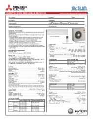
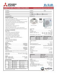
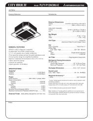
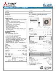
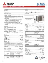
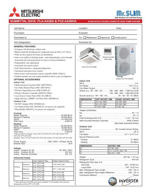
<strong>SUbMITTAL</strong> <strong>DATA</strong>: <strong>PLA</strong>-<strong>A42bA</strong> & <strong>PUZ</strong>-<strong>A42NHA</strong> 42,000 bTU/H CEILINg CASSETTE HEAT PUMP SYSTEM<br />
Job Name: Location: Date:<br />
Purchaser: Engineer:<br />
Submitted to: For Reference<br />
Unit Designation: Schedule No.:<br />
gENErAL FEATUrES<br />
• Compact side-discharge outdoor unit<br />
• Built-in drain lift mechanism for condensate removal; lifts to 33-7/16 in.<br />
• Wide air flow pattern for better air distribution<br />
• Auto wave airflow in heating mode—unit independently cycles through<br />
horizontal and vertical positions for more even heat distribution<br />
• Independent vane adjustment<br />
• Automatic fan speed control<br />
• Self-check function—integrated diagnostics<br />
• Advanced microprocessor control<br />
• Hard-wired, wall-mounted, remote controller (PAR-21MAA)<br />
• Limited warranty: one year on parts and defects and six years on compressor<br />
OPTIONAL ACCESSOrIES<br />
Indoor Unit<br />
• Multi-function Casement (PAC-SH53TM-E)<br />
• Air Outlet Shutter Plates (PAC-SH51SP-E)<br />
• Wireless Signal Receiver (PAR-SA9FA-E)<br />
• Wireless Remote Controller (PAR-FL32MA)<br />
• i-see Sensor Corner Panel (PAC-SA1ME-E)<br />
• High-efficiency (MERV 10) Filter (PAC-SH59KF-E)<br />
Outdoor Unit<br />
• M-NET Adapter (PAC-SF80MA-E)<br />
• Air Outlet Guide (PAC-SG59SG-E; two pieces are required)<br />
• Wind Baffle (WB-PA2; two pieces are required)<br />
Cooling*<br />
Rated Capacity. . . . . . . . . . . . . . . . . . . . . . . . . . . . . . .42,000 Btu/h<br />
Minimum Capacity . . . . . . . . . . . . . . . . . . . . . . . . . . . .18,000 Btu/h<br />
SEER . . . . . . . . . . . . . . . . . . . . . . . . . . . . . . . . . . . . . .14.4 Btu/h/W<br />
Total Input. . . . . . . . . . . . . . . . . . . . . . . . . . . . . . . . . . . . . ..4,600 W<br />
Heating*<br />
Rated Capacity. . . . . . . . . . . . . . . . . . . . . . . . . . . . . . .45,000 Btu/h<br />
Minimum Capacity . . . . . . . . . . . . . . . . . . . . . . . . . . . .18,000 Btu/h<br />
HSPF . . . . . . . . . . . . . . . . . . . . . . . . . . . . . . . . . . . . . . .9.3 Btu/h/W<br />
Total Input. . . . . . . . . . . . . . . . . . . . . . . . . . . . . . . . . . . . . ..4,450 W<br />
* Rating Conditions (Cooling) - Indoor: 80ºF (27ºC) DB, 67ºF (19ºC) WB. Outdoor: 95ºF<br />
(35ºC) DB, 75ºF (24ºC) WB.<br />
(Heating) - Indoor: 70ºF (21ºC) DB, 60ºF (16ºC) WB. Outdoor: 47ºF (8ºC) DB, 43ºF (6ºC) WB.<br />
Power Supply . . . . . . . . . . . . . . . . . . . . 208 / 230V, 1-Phase, 60 Hz<br />
Breaker Size. . . . . . . . . . . . . . . . . . . . . . . . . . . . . . . . . . . . . . . .30 A<br />
Voltage<br />
Indoor - Outdoor S1-S2 . . . . . . . . . . . . . . . . . . . . . . AC 208 / 230V<br />
Indoor - Outdoor S2-S3 . . . . . . . . . . . . . . . . . . . . . . . . . . . .DC 24V<br />
Indoor - Remote Controller. . . . . . . . . . . . . . . . . . . . . . . . . .DC 12V<br />
OPErATINg rANgE<br />
Cooling<br />
Heating<br />
Maximum<br />
Minimum<br />
Maximum<br />
Minimum<br />
Indoor Intake Air Temp. Outdoor Intake Air Temp.<br />
95ºF (35ºC) DB,<br />
71ºF (22ºC) WB<br />
115ºF (46ºC) DB<br />
67ºF (19ºC) DB,<br />
57ºF (14ºC) WB<br />
0ºF** (-18ºC) DB<br />
80ºF (27ºC) DB,<br />
67ºF (19ºC) WB<br />
70ºF (21ºC) DB,<br />
60ºF (16ºC) WB<br />
70ºF (21ºC) DB,<br />
59ºF (15ºC) WB<br />
12ºF (-11ºC) DB,<br />
10ºF (-12ºC) WB<br />
** With optional wind baffle accessory installed. If not installed, the minimum<br />
temperature will be 23ºF (-5ºC) DB.<br />
Indoor Unit: <strong>PLA</strong>-A42BA<br />
Approval Construction<br />
Remote Controller:<br />
PAR-21MAA<br />
Outdoor Unit: PUY-<strong>A42NHA</strong><br />
Indoor Unit<br />
MCA . . . . . . . . . . . . . . . . . . . . . . . . . . . . . . . . . . . . . . . . . . . . . . 2 A<br />
Fan Motor . . . . . . . . . . . . . . . . . . . . . . . . . . . . . . . . . . . 1.00 F.L.A.<br />
Fan Motor Output . . . . . . . . . . . . . . . . . . . . . . . . . . . . . . . . . .120 W<br />
Airflow (Lo - M1 - M2 - Hi) . . . . . . 780 - 880 - 990 - 1,090 Dry CFM<br />
740 - 850 - 950 - 1,060 Wet CFM<br />
Sound Level (Lo - M1 - M2 - Hi) . . . . . . . . . . 34 - 36 - 39 - 41 dB(A)<br />
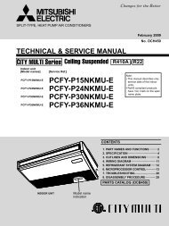
DIMENSIONS UNIT INCHES / MM PANEL INCHES / MM<br />
W 33-1/16 / 840 37-3/8 / 950<br />
D 33-1/16 / 840 37-3/8 / 950<br />
H 11-3/4 / 298 1-3/8 / 35<br />
Weight (Unit/Grille)<br />
lbs. . . . . . . . . . . . . . . . . . . . . . . . . . . . . . . . . . . . . . . . . . . . . 55 / 13<br />
kg . . . . . . . . . . . . . . . . . . . . . . . . . . . . . . . . . . . . . . . . . . . . . . 25 / 6<br />
Field Drainpipe Size O.D.. . . . . . . . . . . . . . . . . . . . . 1-1/4" / 32 mm<br />
Wall-mounted Remote Controller . . . . . . . . . . . . . . . . . PAR-21MAA<br />
(See Data Submittal Sheet)<br />
Outdoor Unit<br />
Compressor . . . . . . . . . . . . . . . . . . . . . . DC Inverter-driven Rotary<br />
MCA . . . . . . . . . . . . . . . . . . . . . . . . . . . . . . . . . . . . . . . . . . . .…26 A<br />
Fan Motor . . . . . . . . . . . . . . . . . . . . . . . . . . . . . . . . .0.4 + 0.4 F.L.A.<br />
Sound Pressure Level<br />
Cooling . . . . . . . . . . . . . . . . . . . . . . . . . . . . . . . . . . . . . . . 51 dB(A)<br />
Heating . . . . . . . . . . . . . . . . . . . . . . . . . . . . . . . . . . . . . . . 55 dB(A)<br />
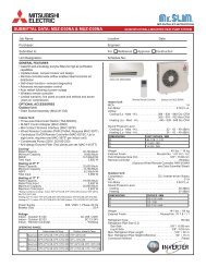
DIMENSIONS INCHES / MM<br />
W 37-3/8 / 950<br />
D 13 + 1-3/16 / 330 + 30<br />
H 53-1/8 / 1,350<br />
Weight . . . . . . . . . . . . . . . . . . . . . . . . . . . . . . . . . .267 lbs. / 121 kg<br />
Refrigerant Type . . . . . . . . . . . . . . . . . . . . . . . . . . . . . . . . . . R410A<br />
Refrigerant Pipe Size O.D.<br />
Gas Side . . . . . . . . . . . . . . . . . . . . . . . . . . . . . . . .5/8" / 15.88 mm<br />
Liquid Side. . . . . . . . . . . . . . . . . . . . . . . . . . . . . . . .3/8" / 9.52 mm<br />
Max. Refrigerant Pipe Length. . . . . . . . . . . . . . . . . . . . . 165' / 50 m<br />
Max. Refrigerant Pipe Height Difference . . . . . . . . . . . . 100' / 30 m<br />
Connection Method . . . . . . . . . . . . . . . . . . . . . . . . . . . . . . . . Flared
25/32 to 1-25/32(20~45)<br />
Ceiling hole<br />
33-27/32 to 35-13/16(860~910)<br />
31-7/8(810)<br />
Ventilation air<br />
intake hole<br />
6-5/16<br />
(160)<br />
Suspension bolt pitch<br />
33-1/16(840)<br />
6-5/16<br />
(160)<br />
5-29/32(150)<br />
3-17/32(90)<br />
* 6-1/16<br />
(170)<br />
* 5-1/2<br />
(140)<br />
Suspension bolt<br />
lower edge<br />
37-3/8 (950)<br />
Air intake grille<br />
Branch duct hole<br />
C<br />
D<br />
Suspension bolt<br />
M10 or 3/8<br />
1<br />
2<br />
19-11/16 (500)<br />
Air outlet hole<br />
3-17/64<br />
(83)<br />
1-27/64<br />
(36)<br />
(50~70)<br />
1-15/16~2-3/4<br />
Ceiling<br />
Grille<br />
Entire<br />
periphery<br />
For MA-Remote controller<br />
terminal block<br />
Corner pocket<br />
23-1/2 (597)<br />
Air intake hole<br />
19-11/16 (500)<br />
Air outlet hole<br />
37-3/8 (950)<br />
Indoor unit<br />
Min.19-11/16(500)<br />
For wiring replacement kit<br />
terminal block<br />
Min.94-1/2(2400)<br />
from floor<br />
Floor<br />
Dimensions: <strong>PLA</strong>-A42BA<br />
15/16 (24)<br />
6-5/16 (160)<br />
Suspension bolt pitch<br />
-3/16 +35<br />
23-13/16 +1-3/8 (605 -5 ) (5/16)<br />
24-13/32 (620)<br />
(7.5)<br />
33-27/32 to 35-13/16 (860~910)<br />
Ceiling hole<br />
(156)<br />
(105)<br />
Ceiling<br />
Grille<br />
23-1/2 (597)<br />
Air intake hole<br />
1-27/64<br />
3-17/64 (36)<br />
(83)<br />
(5/16)<br />
(7.5)<br />
7-3/8<br />
6-5/16<br />
(187.5)<br />
(60)<br />
2-3/8<br />
33-1/16 (840)<br />
(284)<br />
(377)<br />
11-3/16 14-27/32<br />
(160)<br />
Drainpipe connected to<br />
1-1/4 in. O.D. PVC tube<br />
M<br />
M<br />
Indoor unit/Outdoor unit<br />
connecting terminal block<br />
M<br />
M<br />
25/32 to 1-25/32(20~45)<br />
* 4-1/8<br />
* 6-9/64<br />
* 7-15/32<br />
(190)<br />
A<br />
25/32 to<br />
1-25/32<br />
(20~45)<br />
25/32<br />
to 1-25/32<br />
(20~45)<br />
+3/16<br />
11/16 0<br />
(17 +5<br />
0 )<br />
1-3/8<br />
(35)<br />
Drain lift mechanism clean<br />
hole and Drain emergency<br />
drainage hole<br />
Auto vane<br />
(Air outlet)<br />
Vane motor<br />
* B<br />
<strong>PLA</strong>-A24BA<br />
<strong>PLA</strong>-A30BA<br />
<strong>PLA</strong>-A36BA<br />
<strong>PLA</strong>-A42BA<br />
Branch duct<br />
hole<br />
( Connected the attached<br />
flexible pipe or socket.<br />
Keep 25/64(10)to 19/32(15)<br />
between unit ceiling<br />
and ceiling slab.<br />
Detail connecting of branch duct (nominal 6"<br />
round or nominal 4 x 14" rectangular)<br />
3-15/16 (100) 3-15/16 (100)<br />
3-17/32 (90)<br />
3-17/32 (90)<br />
Cut out hole<br />
(ø 175)<br />
Burring hole pitch<br />
( 158)<br />
6-7/32<br />
In case of standard grille<br />
13-25/32<br />
(350)<br />
Burring hole<br />
3-ø 1/8(3-ø 2.8)<br />
Models<br />
1<br />
2 A B C D<br />
<strong>PLA</strong>-A12BA<br />
<strong>PLA</strong>-A18BA<br />
Refrigerant pipe<br />
····ø6.35mm<br />
Flared connection<br />
····1/4<br />
Refrigerant pipe<br />
····ø12.7mm<br />
Flared connection 9-1/2 10-3/16 3-5/32 2-29/32<br />
····1/2<br />
(241) (258) (80) (74)<br />
)<br />
ø 6-7/8<br />
Refrigerant pipe Refrigerant pipe<br />
····ø9.52mm ····ø15.88mm<br />
Flared connection Flared connection<br />
····5/8<br />
11-1/16 11-3/4 3-11/32 3-1/32<br />
····3/8<br />
(281) (298) (85) (77)<br />
ø 5-29/32<br />
(100)<br />
(130)<br />
(ø 150)<br />
Cut out hole<br />
Ceiling<br />
3-15/16<br />
5-1/8<br />
14-ø 1/8<br />
* 6-3/32 (155)<br />
* 6-9/16(167)<br />
(14-ø 2.8)<br />
Burring hole<br />
Detail drawing of ventilation air intake connection<br />
* *<br />
120˚<br />
120˚<br />
Burring hole pitch<br />
ø 4-29/32(ø 125)<br />
Cut out hole<br />
ø 3-15/16(ø 100)<br />
In case of wireless remote controller<br />
Emergency operation switch<br />
Emergency operation<br />
switch<br />
Receiver<br />
DEFROST/STAND BY lamp<br />
Operation lamp<br />
Note1. Use 1-1/4 in. O.D. (32) PVC TUBE.<br />
Drain lift mechanism is included.<br />
2. Suspension bolt, use M10 or W3/8.<br />
(Field supplied)<br />
3. Electrical box may be removed for service purposes.<br />
Make sure to slack the electrical wire little bit for<br />
control/power wires connection.<br />
4. The height of the indoor unit is adjustable with the grille<br />
attached.<br />
5. For the installation of the optional high efficiency filter,<br />
the optional multi-functional casement is required.<br />
1) Add 5-5/16 (135mm) to the dimensions marked with an * in the figures<br />
2) The optional high efficiency filter required optional<br />
multi-functional casement.<br />
6. When installing the branch ducts, be sure to insulate adequately.<br />
Otherwise condensation may occur.<br />
7. As for necessary installation/service space, please refer to the<br />
bottom left figure.
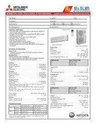
1 FREE SPACE (Around the unit) 2 SERVICE SPACE 3 FOUNDATION BOLTS 4 PIPING-WIRING DIRECTIONS<br />
2-U Shaped notched hole<br />
(Foundation Bolt M10)<br />
Rear Air Intake<br />
Piping and wiring connections<br />
can be made from 4 directions:<br />
front, right, rear and below.<br />
Please secure the unit firmly<br />
with 4 foundation (M10)<br />
bolts. (Bolts and washers must<br />
be purchased locally.)<br />
Dimensions of space needed<br />
for service access are<br />
shown in the below diagram.<br />
The diagram below shows a<br />
basic example.<br />
Explantion of particular details are<br />
given in the installation manuals etc.<br />
175<br />
<br />
600<br />
175<br />
<br />
19<br />
150mm<br />
<br />
FREE<br />
<br />
53 56<br />
28 370<br />
417<br />
45<br />
Side Air Intake<br />
330<br />
FOUNDATION<br />
Max.<br />
30mm<br />
500mm<br />
<br />
Min. 10mm<br />
<br />
Min. 10mm<br />
<br />
Min.<br />
10mm<br />
Min.<br />
Service space 500mm<br />
<br />
Min.Min.<br />
42<br />
66<br />
Air Discharge<br />
30<br />
2-12*36 Oval hole<br />
(Foundation Bolt M10)<br />
Min. 150mm<br />
<br />
Min. 1000mm<br />
<br />
950<br />
Earth terminal<br />
322<br />
Handle<br />
Rear Air Intake<br />
Side Air Intake<br />
Dimensions: <strong>PUZ</strong>-A42nHA<br />
Terminal Block<br />
Left···Power supply wiring<br />
Right····Indoor/Outdoor wiring<br />
Example of Notes<br />
1 ····Refrigerant GAS pipe connction (FLARE)[ 15.88<br />
2 ····Refrigerant LIQUID pipe connection (FLARE)[ 9.52<br />
*1 ····Indication of STOP VALVE connection location.<br />
Service panel<br />
Handle<br />
Handle<br />
1350<br />
1076<br />
1<br />
* 1 447<br />
* 1 443<br />
2<br />
371 635<br />
23<br />
Handle<br />
Handle<br />
Air intake<br />
Piping Knockout Hole Details<br />
Front piping cover<br />
Rear piping cover<br />
71<br />
71<br />
When installing the conduit.<br />
Set the attachment to the<br />
inner side of each panel.<br />
1/2 Conduit attachment<br />
2-ø22.2<br />
Conduit hole<br />
(2-ø27Knockout)<br />
Conduit hole<br />
(2-ø27Knockout)<br />
(Knockout) Right trunking hole<br />
(Knockout)<br />
75<br />
45 40<br />
40<br />
Rear trunking hole<br />
(Knockout)<br />
40<br />
31<br />
74<br />
<br />
ø92<br />
Rear piping hole<br />
(Knockout)<br />
65<br />
92<br />
27 55<br />
23 73<br />
63<br />
<br />
ø92<br />
19 55<br />
92<br />
23 27<br />
92<br />
73 63<br />
Right piping hole<br />
Conduit hole<br />
(2-ø27Knockout)<br />
45<br />
40<br />
Front trunking hole<br />
(Knockout)<br />
Bottom piping hole<br />
(Knockout)<br />
27 55<br />
63<br />
<br />
23 73<br />
ø92<br />
<br />
Front piping hole<br />
(Knockout)<br />
Drain hole<br />
5-ø 33<br />
145 145 145<br />
<br />
220<br />
<br />
81 219<br />
30<br />
92<br />
65
C SD - <strong>PLA</strong>-A42BA / <strong>PUZ</strong>-<strong>A42NHA</strong> - 200710 © MITSUBISHI ELECTRIC / HVAC 2007<br />
noTes<br />
3400 Lawrenceville Suwanee Rd<br />
Suwanee, GA 30024<br />
Tele: 678-376-2900 • Fax: 800-889-9904<br />
Toll Free: 800-433-4822 (#3)<br />
www.mehvac.com<br />
Specifications are subject to change without notice.