FDM 19-10-30 - Wisconsin.gov
FDM 19-10-30 - Wisconsin.gov
FDM 19-10-30 - Wisconsin.gov

Create successful ePaper yourself
Turn your PDF publications into a flip-book with our unique Google optimized e-Paper software.
Facilities Development Manual <strong>Wisconsin</strong> Department of Transportation<br />
Chapter <strong>19</strong> Plans, Specifications and Estimates<br />
Section <strong>10</strong> PS&E Transmittal and Composition<br />
<strong>FDM</strong> <strong>19</strong>-<strong>10</strong>-1 Transmittal of Let Project PS&Es October 22, 2012<br />
This procedure describes the requirements for transmitting a let project PS&E to central office. Guidance for<br />
LFA agreement PS&Es is located in <strong>FDM</strong> <strong>19</strong>-25-5. Direct questions to the Plans & Estimates Specialist at (608)<br />
266-<strong>10</strong>20.<br />
A LET project PS&E transmittal consists of an electronic plan submittal. All exhibits must be sent electronically<br />
to the BPD using eSubmit.<br />
1.1 Accessing eSubmit<br />
To access the WisDOT eSubmit Application you must have both of the following: 1) A valid <strong>Wisconsin</strong> User ID<br />
and password; and 2) Authorization from WisDOT.<br />
1.1.1 Creating a <strong>Wisconsin</strong> User ID<br />
To create a <strong>Wisconsin</strong> User ID, go to https://on.wisconsin.<strong>gov</strong>/WAMS/SelfRegController and follow the<br />
instructions. Individuals, not companies, are associated with WI User IDs.<br />
1.1.2 Requesting Authorization from WisDOT<br />
After creating your WI User ID, send an email requesting eSubmit access to david.domabyl@dot.wi.<strong>gov</strong> and<br />
eric.arneson@dot.wi.<strong>gov</strong>. Include your full name and phone number in your request. Consultants requesting<br />
eSubmit access must also include a 2-sheet ePlan PDF with their request. Sheet 1 must be a title sheet created<br />
from scanned hardcopy. Sheet 2 must be a plan & profile sheet created from your CAD system. Both sheets<br />
must comply with <strong>FDM</strong> 15-5-<strong>10</strong>. If you have a valid WI User ID, and (consultants only) the 2-sheet ePlan<br />
complies with <strong>FDM</strong>s, you will be granted eSubmit access and a confirmation will be emailed to you.<br />
IMPORTANT: All electronic exhibits must be free of viruses. If an infected exhibit is submitted, the submitter will<br />
receive a confirmation that it was sent. However, it will be immediately and automatically deleted and will not be<br />
accessible by WisDOT staff.<br />
1.2 Submitting Roadway Plans with eSubmit<br />
After you have been granted eSubmit access, you may browse to the eSubmit application at:<br />
https://trust.dot.state.wi.us/ESubmit/.<br />
From the main “Electronic Submittal System” page, select "Roadway Plans and Exhibits". In the top section of<br />
the “Submit Roadway Plans and Exhibits” page, provide required information about the submittal.<br />
Comments: Enter up to 80 characters of special information including any appropriate message for the<br />
recipients, i.e., Original, Revision, Insert, Advanceable Plan, Resubmittal per comments, etc. Otherwise enter<br />
“NA.”<br />
Let Date: Select the year and month in which the project is scheduled for letting or check ExLET.<br />
Submittal Status: Select the Submittal Status. The choices are: <strong>30</strong>%, 60%, 90%(which are for Pre-PS&E) and<br />
Final PS&E (which is for a Final Submittal)Submittals generally include the following exhibits: ePlan, SDD<br />
Spreadsheet, Plan Letter, Environmental Commitments, Special Provisions, Time for Completion, Governor<br />
Bond, Proposal Cover, Right of Way Certification, Utility Status Report and Trns•port Estimate. Final PS&E and<br />
ExLET submittals include all exhibits.<br />
WisDOT Office: Select the WisDOT Region Office. The choices are: Eau Claire, Green Bay, La Crosse,<br />
Madison, Rhinelander, Superior, Waukesha, <strong>Wisconsin</strong> Rapids and Operations. (For Work Share projects,<br />
select the “giving” Region).<br />
Construction Project ID: Enter the 8-digit Construction ID using the format: 00000000. Do not enter dashes. Do<br />
not enter a Design ID. If there are multiple ID numbers shown on the title sheet of the plan, enter the lowest ID<br />
number.<br />
Additional Project IDs: If there are multiple Construction IDs shown on the title sheet and or with the plan, enter<br />
the lowest ID on the previous line. Enter the rest of the IDs here. Enter the IDs using the format: 00000000. Do<br />
not enter dashes. Do not enter Design IDs. Separate multiple IDs using commas. If there are no additional IDs,<br />
enter “NA.”<br />
Page 1
<strong>FDM</strong> <strong>19</strong>-<strong>10</strong> PS&E Transmittal and Composition<br />
Structures: If there are structures on the project, enter the structure numbers using the format B-00-000 for<br />
Bridges, C-00-000 for Culverts, R-00-000 for Retaining walls, S-00-000 for Sign bridges, N-00-000 for Noise<br />
barriers M-00-000 for Miscellaneous Structures and P-00-000 for Bridges with no record plans on file. Separate<br />
multiple numbers with commas. If there are no structures, enter “NA.”<br />
Route Name: Enter the route name (e.g. USH 45).<br />
Project Name: Enter the project name (e.g. CTH Y – <strong>10</strong>TH Avenue).<br />
WisDOT Design Contact/Phone: Enter the WisDOT Region Office Design Contact’s full name and phone<br />
number (e.g. Jane Doe / 608-334-4556).<br />
Consultant Design Contact/Phone: If applicable, enter the Consultant Contact’s firm name, full name and phone<br />
number (e.g. ABC Consulting Engineers Inc., John Buck / 608-334-4556). Otherwise, enter “NA.”<br />
In the middle section of the “Submit Roadway Plans and Exhibits” page, specify the exhibits to submit. At least<br />
one exhibit is required. See also <strong>FDM</strong> <strong>19</strong>-<strong>10</strong>-<strong>10</strong>.<br />
1.2.1 Naming Exhibits<br />
Each electronic exhibit must be named using the Construction ID number, with no dashes, plus the 3-letter code<br />
shown below indicating the type of exhibit. An underbar “_” must be used between the Construction ID and the<br />
3-letter code. See Table.1.1.<br />
When multiple Construction IDs are shown on a single title sheet, submit all the exhibits under the lowest ID.<br />
When multiple plans with multiple title sheets are tied together, submit each plan and SDD spreadsheet<br />
individually using the appropriate ID for each.<br />
Exhibit<br />
Electronic Plan<br />
Standard Detail Drawing List<br />
Plan Letter<br />
Environmental Commitments<br />
Special Provisions<br />
Special Provision Insert<br />
Contract Time for Completion<br />
Governor’s Approval Form<br />
Proposal Cover<br />
Right-of-Way Certification<br />
Table 1.1 Exhibits and Requirements<br />
Required Exhibit File Type and File Name<br />
where 00000000 is the associated Construction ID<br />
Adobe PDF named 00000000_pln.pdf<br />
Excel spreadsheet named 00000000_sdd.xlsm<br />
Word document named 00000000_ltr.doc or .docx<br />
Adobe PDF named 00000000_env.pdf<br />
Word document named 00000000_xyz.doc or .docx, where xyz is the<br />
region office (eau, gre, lax mad, rhi, sup, wke, wis, or ops).<br />
Word document named 00000000_ins.doc or .docx<br />
Excel spreadsheet or Adobe PDF named 00000000_tim.xls, .xlsx or .pdf<br />
Word document named 00000000_<strong>gov</strong>.doc or .docx<br />
Word document named 00000000_pro.doc or .docx<br />
Adobe PDF named 00000000_row.pdf<br />
Please (remove instructions before submitting)<br />
More<br />
Information<br />
<strong>FDM</strong> 15-5-<strong>10</strong><br />
<strong>FDM</strong> 15-5-15<br />
<strong>FDM</strong> <strong>19</strong>-<strong>10</strong>-15<br />
<strong>FDM</strong> 15-5-15<br />
<strong>FDM</strong> <strong>19</strong>-15-1<br />
<strong>FDM</strong> <strong>19</strong>-15-1<br />
<strong>FDM</strong> <strong>19</strong>-<strong>10</strong>-<strong>30</strong><br />
<strong>FDM</strong> <strong>19</strong>-<strong>10</strong>-20<br />
<strong>FDM</strong> <strong>19</strong>-<strong>10</strong>-25<br />
<strong>FDM</strong> <strong>19</strong>-<strong>10</strong>-35<br />
Page 2
Utilities Status Report<br />
Project Data<br />
(in-house design)<br />
Project Data<br />
(consultant design)<br />
Estimate<br />
Proposal Level Preliminary<br />
Detail Estimate<br />
<strong>FDM</strong> <strong>19</strong>-<strong>10</strong> PS&E Transmittal and Composition<br />
Adobe PDF named 00000000_usr.pdf<br />
(remove instructions before submitting)<br />
In File Cabinet System<br />
Compressed file named 00000000_dat.zip<br />
Loaded in Trns•port (PES) System<br />
Adobe PDF named 00000000_est.pdf<br />
<strong>FDM</strong> <strong>19</strong>-<strong>10</strong>-40<br />
<strong>FDM</strong> <strong>19</strong>-<strong>10</strong>-43<br />
<strong>FDM</strong> <strong>19</strong>-<strong>10</strong>-43<br />
<strong>FDM</strong> <strong>19</strong>-5-1<br />
<strong>FDM</strong> <strong>19</strong>-5<br />
Exhibit <strong>10</strong>.7<br />
Click the Browse button in eSubmit to the right of each exhibit you wish to submit. When the “Choose file” dialog<br />
appears, browse to the exhibit on your computer or network. Repeat until you have specified all the exhibits you<br />
wish to submit.<br />
1.2.2 Naming Special Provisions<br />
Note that the Special Provisions are named with a 3-letter code corresponding to the applicable WisDOT Region<br />
Office as shown below.<br />
Region<br />
Office City<br />
Three-Letter<br />
Code<br />
Green<br />
Bay<br />
Table 1.2 Region Office Cities and 3-Letter Codes<br />
Eau<br />
Claire<br />
La<br />
Crosse<br />
Madison Rhinelander Superior Waukesha <strong>Wisconsin</strong><br />
Rapids<br />
gre eau lax mad rhi sup wke wis<br />
1.2.3 Modifying Exhibits<br />
The eSubmit system appends the Submittal Status, Date and Time to each exhibit as it is copied to the WisDOT<br />
network. This suffix serves as the exhibit revision number. The format is SSS_YYMMDD_TIME. SSS is<br />
Submittal Status (0<strong>30</strong>, 060, 090 or PSE). YY is Year, MM is Month and DD is Date. Time is in 24-hour format.<br />
For example: a PSE ePlan for project 11<strong>30</strong>2072 submitted at 4:03 PM on September 16, 2005 would be named:<br />
11<strong>30</strong>2072_pln_pse_050916_1603.pdf.<br />
When modifying exhibits, the entire exhibit must be re-submitted (except for special provisions). When modifying<br />
exhibits, include the words “revised exhibits” on the comments line.<br />
1.2.4 Modifying Special Provisions<br />
There are two ways to modify special provisions, inserts and revisions.<br />
Inserts are used when there are a relatively small number of changes to the special provisions. Only the portion<br />
that is actually being changed needs to be re-submitted. Modifications should be made to special provisions<br />
using inserts whenever possible. Inserts must be named 00000000_ins.doc or docx, where 00000000 is the<br />
associated Construction ID. When submitting special provision inserts, include the words “special provision<br />
insert” on the comments line, and send an email to the special provisions editor informing her/him that an insert<br />
has been submitted.<br />
When submitting an insert, use the document Special Provisions Insert and follow the directions in Insert<br />
Guidelines located at http://on.dot.wi.<strong>gov</strong>/consultants/stsp/index.shtm. Preface the changes with detailed directions on<br />
where the revised language should be inserted, and, if necessary, which language in the special provisions<br />
should be deleted. For example, the directions may state “Delete paragraph three, which begins with the words<br />
“beginning words of paragraph three,” of the existing Utilities article and replace with the following paragraph<br />
“text of new paragraph.” Follow these guidelines for preparing inserts for special provisions:<br />
1. If changes are needed to existing articles, provide detailed directions on where the revised language<br />
should be inserted, and which language in the special provisions should be deleted. An example is: “In<br />
bid item SPV.0060.01, Cleaning and Painting Pole, delete paragraph three in section C Construction.<br />
Page 3
<strong>FDM</strong> <strong>19</strong>-<strong>10</strong> PS&E Transmittal and Composition<br />
The third paragraph begins with the words “Blast-clean the pole with...”<br />
2. If adding an STSP, simply provide the number of the STSP. (Do not send the entire STSP.)<br />
3. If deleting articles, provide the title of the article, NOT the article number, because articles are<br />
frequently rearranged during the review process. For example, delete the article for bid item<br />
SPV.0<strong>10</strong>5.01, Remove Traffic Signals at Intersection (STH 33 and USH 12).<br />
It is preferred that, if at all possible, changes to special provisions are submitted as an insert. However, it may<br />
be necessary when there are so many changes that the entire special provision must be re-submitted as a<br />
revision. Never submit a revision without first checking with the special provisions editor or the special<br />
provisions coordinator.<br />
If an insert is being submitted late in the plan-review process (later than 4 weeks before the Ad Meeting date for<br />
that proposal’s letting), send an email to the special provisions editor, angela.clary@dot.wi.<strong>gov</strong>, in addition to<br />
eSubmitting the insert.<br />
1.2.5 Submittal<br />
In the bottom section of the “Roadway Plans and Exhibits” page, specify who will receive notification that the<br />
submittal was sent. An email notification is sent automatically to WisDOT staff when roadway exhibits are<br />
submitted. Recipients are determined based on the Submittal Status selected by the submitter. The email<br />
contains the same information that is included on the confirmation page. The submitter also receives a copy of<br />
the email notification. It is sent to the email address specified by the submitter at the time he/she created their<br />
<strong>Wisconsin</strong> eSubmit User ID (their extranet ID).<br />
Under “Notify additional affected parties,” check the boxes that are applicable for the project. Email notifications<br />
will also be sent to appropriate WisDOT staff in those areas.<br />
For workshare projects only, select the “receiving” Region.<br />
Additional email addresses may be entered manually on the “Additional Emails” line. Separate multiple email<br />
addresses with commas.<br />
The submitter is required to include their phone number as it may be different than the Contact Phone number.<br />
Before clicking the Submit button, review the information you have entered. You will not be prompted to confirm<br />
when you press Submit. The submittal will begin immediately.<br />
Click the Submit button once and wait. Exhibits may take several minutes to upload depending on your Internet<br />
connection speed.<br />
When processing is complete, you will see a confirmation page like Figure 1.1. If you do not see the<br />
confirmation page, the submittal was not successful. Please attempt submittal a second time before contacting<br />
608-266-<strong>10</strong>20 or the DOT help desk at 608-266-9434.<br />
1.2.6 Submitting Structure Plans<br />
http://on.dot.wi.<strong>gov</strong>/dtid_bos/extranet/structures/structure_esubmithelp.pdf<br />
Page 4
<strong>FDM</strong> <strong>19</strong>-<strong>10</strong> PS&E Transmittal and Composition<br />
Figure 1.1. Sample eSubmit Confirmation Page<br />
1.2.7 Error Messages<br />
Review the confirmation page. Verify that it contains no error messages. Two common errors are shown below.<br />
The error “resource not found” or “destination folder does not exist” indicates that the required destination folder<br />
at WisDOT does not exist. See Figure 1.2. Contact the individual responsible for receiving the exhibits. Verify<br />
that they are expecting your submittal and have created the appropriate folder on the WisDOT network.<br />
Page 5
<strong>FDM</strong> <strong>19</strong>-<strong>10</strong> PS&E Transmittal and Composition<br />
Figure 1.2. Sample eSubmit Error Report<br />
The error “File not found” indicates that the file specified cannot be found on your computer or network. See<br />
Figure 1.3. Verify that the path and filename are correct and try again. This error will also occur when an empty<br />
file (zero bytes) is specified.<br />
Figure 1.3. Sample eSubmit Error Report<br />
<strong>FDM</strong> <strong>19</strong>-<strong>10</strong>-5 Final Review October 22, 2012<br />
This procedure reviews steps that should be completed prior to PS&E submittal.<br />
5.1 Approval of Plans and Grades<br />
Approval of plans and grades shall be completed prior to the submittal of the PS&E. These approvals are<br />
covered in <strong>FDM</strong> 3-20-45. A local unit of <strong>gov</strong>ernment is required to approve plans and grades even if they are not<br />
participating in the funding.<br />
5.2 Cost Effectiveness Finding<br />
When a local unit of <strong>gov</strong>ernment is to construct a highway project with its own forces and equipment under a<br />
LFA agreement, a CEF shall be approved prior to submittal of the PS&E. The CEF is covered under <strong>FDM</strong> 3-20-<br />
12.<br />
5.3 Hazardous Materials<br />
The remediation of hazardous materials should be completed and project location certified as either within<br />
acceptable limits or free of contamination prior to letting the contract to bids where practicable. If remediation<br />
during construction would be advantageous, every effort should be made to plan for efficient coordination with<br />
construction operations. See <strong>FDM</strong> 21-35-20.<br />
5.4 Right of Way and Encroachments<br />
The acquisition of all right of way, including PLE, TLE construction permits and right of entry, should be<br />
completed prior to submittal of the PS&E.<br />
The disposition of all encroachments should also be determined prior to submittal.<br />
Page 6
<strong>FDM</strong> <strong>19</strong>-<strong>10</strong> PS&E Transmittal and Composition<br />
See Chapter 12 of this manual or the Real Estate Program Manual for detailed information.<br />
5.5 Permits and Environmental Documents<br />
All permits and environmental documents necessary to construct the contract should be completed prior to<br />
submittal of the PS&E. See Chapter 21 for detailed information.<br />
5.6 Utilities and Railroads<br />
Utility and railroad agreements, utility and railroad land interests and arrangements for moving utilities should be<br />
complete prior to submittal of the PS&E. See Chapters 17 and 18 for detailed information.<br />
5.7 Justifications<br />
Justifications for cattle passes or other exceptional items should be cleared prior to submittal of the PS&E. Nonstandard<br />
items or requirements that do not require formal approval are to be addressed in the Plan Letter.<br />
5.8 Proprietary Products<br />
The use of proprietary products in a contract should be approved prior to the submittal of the PS&E. See <strong>FDM</strong><br />
<strong>19</strong>-1-5.<br />
<strong>FDM</strong> <strong>19</strong>-<strong>10</strong>-<strong>10</strong> Required Exhibits October 22, 2012<br />
<strong>10</strong>.1 List of Exhibits<br />
The following products, referred to as exhibits, comprise a final PS&E. transmittal. The exhibits submitted to the<br />
BPD vary with the type of project.<br />
1. ePlan: Required for all transmittals. (See <strong>FDM</strong> 15)<br />
2. SDD Spreadsheet: Required for all transmittals. (See <strong>FDM</strong> 15-5-15).<br />
3. Plan Letter: Required for all transmittals. (See <strong>FDM</strong> <strong>19</strong>-<strong>10</strong>-15).<br />
4. Environmental Commitments: Required for all transmittals.<br />
5. Special Provisions: Required for all transmittals. (See <strong>FDM</strong> <strong>19</strong>-15-1).<br />
6. Time For Completion (Form DT<strong>19</strong>23): Required for all contracts, including agreements where the<br />
county or local units of <strong>gov</strong>ernment are doing the work with their own forces (e.g., LFA) (see <strong>FDM</strong> <strong>19</strong>-<br />
<strong>10</strong>-<strong>30</strong>).<br />
7. Governor Bond (Form DT25): Required for all projects over $5,000. (See <strong>FDM</strong> <strong>19</strong>-<strong>10</strong>-20).<br />
8. Proposal Cover: Required for all LET contracts. This exhibit consists of Form DT1502 prepared as a<br />
cover, together with the Special Provisions and a list of Additional Special Provisions pertinent to the<br />
contract (See <strong>FDM</strong> <strong>19</strong>-<strong>10</strong>-25). Information concerning LFA agreements is contained in Section 25 of<br />
this chapter. Form DT1502 is available is available at the same location as the STSPs:<br />
http://on.dot.wi.<strong>gov</strong>/consultants/stsp/index.shtm (See <strong>FDM</strong> <strong>19</strong>-15-85). The Sample Proposal shall be<br />
submitted in electronic format via the e-Submit to the BPD.<br />
9. Right of Way Cert (Form DT1899): Required for all transmittals. (See <strong>FDM</strong> <strong>19</strong>-<strong>10</strong>-35.)<br />
<strong>10</strong>. Utility Status Report (Form DT<strong>10</strong>80): Required for all transmittals. (See <strong>FDM</strong> <strong>19</strong>-<strong>10</strong>-40).<br />
11. Project Data: Required for in-house design.<br />
12. Project Data: Required for consultant design.<br />
13. Estimate: Required for all transmittals.<br />
14. Trns•port Estimate: Required for all transmittals (See <strong>FDM</strong> <strong>19</strong>-5, Exhibit <strong>10</strong>.6). LFA agreements<br />
require electronic estimates for all projects over $25,000.<br />
<strong>FDM</strong> <strong>19</strong>-<strong>10</strong>-15 Plan Letter March 4, 2013<br />
A plan letter is to accompany all PS&E transmittals - including both bid contracts and force account agreements.<br />
Its objective is to provide BPD the information required to authorize the plan and process the PS&E without<br />
delays. It also informs others within the department of the transmittal and its general concepts.<br />
The plan letter template is available at http://on.dot.wi.<strong>gov</strong>/consultants/stsp/index.shtm. The most current version of<br />
the plan letter must be submitted at P.S. & E. stage, or the designer will be required to resubmit the letter. The<br />
Page 7
<strong>FDM</strong> <strong>19</strong>-<strong>10</strong> PS&E Transmittal and Composition<br />
plan letter contains fields for entering required information. The tab key or the up and down arrows on your<br />
keyboard allow the user to move from one field to the next field. Text can be copied from other sources and<br />
pasted into the form fields. Images and tables should not be copied into a field.<br />
15.1 Plan Letter Contents<br />
Attachment 15.1 shows the outline of a sample plan letter.<br />
15.1.1 Header<br />
The plan letter is addressed to the Chief Proposal Management Engineer, BPD, Room 601 Hill Farms. The plan<br />
letter includes in its headings, the name and title of the person who approved the PS&E submittal. For STH<br />
system projects, this person is the PDS Supervisor; for local system projects, this person is the region’s<br />
Management Consultant. Also include the subject project titles as shown on the title sheet. The first project title<br />
listed must be the controlling project ID, followed by all other project titles. Also include the bid letting date and<br />
the associated design project ID.<br />
15.1.2 Introduction<br />
Include the following information in the introduction:<br />
1. Project description i.e. general location and type of work. If the project involves structure work then<br />
specify what obstacle the structure is spanning (e.g. Rock River, STH 21, or C&NW Railroad)<br />
2. Contract type (LET or, LFA agreement).<br />
3. PS&E due date. One of the quarterly dates each year (February 1, May 1, August 1 and November 1)<br />
which the PS&E is intended to meet.<br />
4. Anticipated construction start date. Obtain this from Form DT<strong>19</strong>23, Contract Time for Completion. See<br />
<strong>FDM</strong> <strong>19</strong>-<strong>10</strong>-<strong>30</strong> Attachment <strong>30</strong>.1.<br />
5. Name, phone number, and e-mail address of the region design contact person. For consultant design<br />
projects, also include the name, phone number and e-mail address of the consultant designer.<br />
6. Name, phone number and e-mail address of the region person to contact for project information after<br />
the project is advertised for bids.<br />
7. National highway system. See <strong>FDM</strong> 4-1-20.2 for definition and map.<br />
8. Prequalification should only be waived for unique projects that may have nontraditional contractors<br />
bidding on the project.<br />
15.1.3 Pre-Bid Meeting<br />
During project development it may become apparent that extraordinary circumstances connected to the project<br />
may be difficult to communicate to the bidders in the usual project documents. When such is the case, a pre-bid<br />
meeting may be appropriate. Indicate if the pre-bid meeting is mandatory or optional. If the pre-bid meeting is<br />
mandatory it must be identified in the advertisement for bids.<br />
A pre-bid meeting is usually of value only on projects of a unique or innovative nature, and would probably be<br />
non-productive on the more routine projects. The date, time, and location of the pre-bid meeting and the topics<br />
to be discussed should be indicated. This information will then be included in the advertisement for bids.<br />
The pre-bid meeting shall be held at least three weeks prior to the letting.<br />
The types of information which could be effectively furnished in this manner are: alternative contracting methods<br />
being used, new construction methods required; complex traffic handling requirements; special coordination<br />
between contractors or with others; stage construction requirements; site access restrictions during<br />
construction; etc. as project aspects may require.<br />
15.1.4 Environmental Documents<br />
The type of environmental document for each project under this contract shall be identified using the FHWA’s<br />
designation as follows:<br />
Page 8
1 - FEIS Year & EIS No. - Draft and Final EIS<br />
<strong>FDM</strong> <strong>19</strong>-<strong>10</strong> PS&E Transmittal and Composition<br />
4- FONSI - Environmental Assessment/Finding of NO Significant Impact<br />
2C- ER - Environmental Report<br />
2B- pER - Programmatic Environmental Report<br />
2A- CE - No Documentation Required<br />
Include the date of approval of the environmental document.<br />
Note any specific commitments made to outside agencies for the purpose of mitigating environmental impacts,<br />
and state how the plans and specifications make provisions for them. Also include the status of required<br />
permits.<br />
If there are any commitments for which provisions have not been made, and explanation should be given.<br />
E-submit the Environmental Commitments Sheet of the Basic Environmental Screening worksheets with your<br />
P.S. & E. submittal. Submit in the following format: 12345678_env.pdf. This information is forwarded to FHWA<br />
for oversight projects.<br />
15.1.5 Permits<br />
On projects of a type where a 404 permit could be required, a statement should be included to the effect that<br />
either a 404 permit is not required or that a 404 permit is required. If required, state what it is for, the type of<br />
permit (including Nationwide No.) and its effective and expiration dates.<br />
If it is anticipated that project completion will extend beyond the 404 permit expiration date, it should be noted. A<br />
copy of the special conditions from the 404 permit (including those specified in the U.S. Army Corps of<br />
Engineers transmittal letter) should be attached to the plan letter.<br />
15.1.6 Right-of-Way and Utilities<br />
Provide brief status of right-of-way acquisition and relocations (i.e., is acquisition complete? If not, when will it be<br />
completed?) or indicate their absence. Indicate if the ROW is clear of encroachments and utilities or, if not, the<br />
expected date of clearance. Identify any utility or other outside force work which will be in progress during the<br />
construction operations and may affect the contract time.<br />
15.1.7 Sanitary Sewer and Water Main<br />
Provide the status of DNR approval of the sanitary sewer and water main, the status of any grants or loans for<br />
these facilities, the status of rights of entry for service connections and the status of any hazardous materials<br />
issues.<br />
15.1.8 Railroads<br />
Identify all railroad grade separations, railroad at grade crossings and encroachments on railroad right of way<br />
that are located within the contract limits. Indicate if railroad work will be in progress during construction<br />
operations. Give the status of all railroad coordination necessary to let the proposal.<br />
15.1.9 Hazardous Materials<br />
Indicate if there are hazardous materials located within the ROW and what steps have been taken to remediate<br />
or clean up the contaminated site(s).<br />
15.1.<strong>10</strong> Design Data<br />
Deviations from design criteria not previously approved are to be explained here. (Materials, specifications, or<br />
special items should be covered in the special provisions portion of the plan letter.)<br />
15.1.11 Structures<br />
List the structure numbers of all structures to be constructed under the contract (e.g., B-40-139). Also include<br />
structure numbers for sign bridges, retaining walls, noise barriers, and high mast lighting foundations.<br />
15.1.12 Landscape Architecture<br />
Remember to route PS&Es with landscaping to the Roadside Management Section in the BHO prior to submittal<br />
of the PS&E to the BPD. Include the date of review completion in the SoRD at the end of the plan letter.<br />
Page 9
<strong>FDM</strong> <strong>19</strong>-<strong>10</strong> PS&E Transmittal and Composition<br />
Note all the requirements for landscape architecture. This includes:<br />
- Aesthetic design elements for structures that have been identified under “Structures.”<br />
- Roadside vegetation management elements:<br />
- Note landscape plantings to be installed under this contract or a subsequent contract.<br />
- Note efforts to save existing vegetation.<br />
- Note roadside clearing to be performed outside of the grading limits.<br />
- Identify who will maintain the plantings after the contract has expired.<br />
15.1.13 Traffic Signals<br />
List all intersections where traffic signals will be constructed under the contract.<br />
15.1.14 Traffic<br />
State how traffic will be accommodated during construction (construction under traffic, detour, etc.). If a detour<br />
will be used explain the location and how the signing will be accomplished.<br />
Indicate the approval date for the TMP.<br />
Indicate the date when the Finished Traffic Control Plan & Review Meeting was held, if applicable.<br />
15.1.15 Alternative Contracting<br />
If the project is using alternative contracting methods (“enhanced” liquidated damages, interim liquidated<br />
damages, incentives/disincentives, cost plus time bidding, or lane rentals), they should be discussed here.<br />
15.2.16 Special Provisions<br />
List only unusual standard specification modifications and unusual special items so that central office staff can<br />
identify their application to the contract. This will be needed for only those changes that are not self-explanatory<br />
or have not become a region standard modification to fit specific regional characteristics. Do not list STSP if the<br />
only modifications made were to complete the blank fields within the STSP.<br />
15.2.17 Standardized Special Provisions<br />
Include any changes that were made to the STSPs. There is no need to list the STSP, if the only modifications<br />
made were to complete the blank fields within the STSP.<br />
15.2.18 Plans and Proposals<br />
Indicate the number of 11” x 17” plans and the number of sample proposals that are needed by the region or<br />
local program manager for contract administration.<br />
15.2.<strong>19</strong> Sign Details<br />
A. Local Program PS&E Submittals<br />
1. Insert ALL sign plates (standard & special) into the plan before E-submitting.<br />
B. ALL Other PS&E Submittals (prior to E-Submittal)<br />
1. Special Sign Plates. If not done prior to the 90% PS&E Review Process, request a pdf file of all special<br />
sign plates from Central Office’s Bureau of Highway Operations/Traffic at 266-0150 a minimum of<br />
three weeks prior to PS&E Submittal.<br />
2. Standard Sign Plates. Prior to the 90% PS&E review, request that Central Office’s Bureau of Highway<br />
Operations/Traffic, at 266-0150, reviews the project and creates a pdf file of the required standard sign<br />
plates. In the plan letter, list all standard sign plates required for the project.<br />
15.2.20 Additional Special Provisions<br />
Include a list of the ASPs (refer to <strong>FDM</strong> <strong>19</strong>-15-90) that are to be inserted by the BPD when assembling the<br />
proposal. ASP4, 6, 7 and 9 are included with every proposal. If ASP 1 is requested, include the number of<br />
graduates and apprentices and the total number of hours requested for each category.<br />
15.2.21 Functional Classification of Road<br />
Specify if the road being improved is/or is not a local road or rural minor collector.<br />
15.2.22 Force Account Agreements<br />
Letters for force account agreement projects must state that the submitted agreement is within the policy limits<br />
(see <strong>FDM</strong> 3-20-12). If the agreement exceeds policy limits the letter must include the date of approval of<br />
Page <strong>10</strong>
exceptions to the stated policy.<br />
<strong>FDM</strong> <strong>19</strong>-<strong>10</strong> PS&E Transmittal and Composition<br />
15.2.23 Conclusion<br />
Use this section to explain any unique features of this PS&E that are not addressed in any other section of the<br />
plan letter. Indicate when special DWD wage rates are attached to the plan letter and should be inserted in the<br />
Highway Work Proposal. If a proposal involves significant non-standard highway work such as building<br />
construction or other work effort involving non-standard highway/structure trades, the region or their consultant<br />
shall apply to DWD for the special wage rates and include these wage rates as part of the PS.&E submittal. The<br />
wage rates should also be scanned and converted to PDF files and sent electronically with the other electronic<br />
documents.<br />
15.2.24 PS&E Review Summary<br />
This document is a summary certification of all the reviews the PS&E has undergone from central office staff.<br />
This must be filled in for each project to be LET.<br />
LIST OF ATTACHMENTS<br />
Attachment 15.1 Plan Letter<br />
<strong>FDM</strong> <strong>19</strong>-<strong>10</strong>-20 Governors Approval Form (DT25) October 22, 2012<br />
The official name for this document is the Recommendation to Governor for Contract and Bond Approval. The<br />
purpose of this form is to obtain the Governor's approval of a contract while the BPD is processing the contract<br />
itself. The BHO will create and process this form for LFA (state) contracts.<br />
Click here to access a working copy of Form DT25 on the internet. Look under “Doing Business.”<br />
Regions shall complete this form to the extent indicated in Attachment 20.1. Regions shall submit this form as a<br />
PS&E exhibit. In addition, the following procedures will be followed when completing this form.<br />
1. Include any applicable federal project numbers, if known, along with state project I.D. numbers in the<br />
upper left box.<br />
2. Do not show any values for "Contract Amount" or "WisDOT Confidential Estimate."<br />
3. Do not fill in the "Date Let" line if there is a significant chance a project will be moved from one letting<br />
to another.<br />
4. Bonds are required for all contracts with private contractors. Bonds are not required for contracts with<br />
other <strong>gov</strong>ernmental agencies.<br />
5. Fill in only the "State I.D." column of the area entitled "Project Funding Percentages." The other<br />
columns should be left blank. The BPD will complete them.<br />
6. For the following parts of the form:<br />
Project(s) requested by or purpose: Please focus on the purpose of the project. Explain briefly, but<br />
with adequate detail, why this project is being constructed.<br />
Work consists of: A brief description of the work required for the project. Please refrain from using<br />
technical terms. Write in such a way that the common person could understand what is being stated.<br />
Use enough detail so that the reader can readily understand the relative size and scope of the project.<br />
Consequences if not approved: Explain briefly what would occur if the project is not constructed. For<br />
LFA agreements, the cost savings identified by the CEF must be shown. When a programmatic<br />
finding applies (see <strong>FDM</strong> 3-20-12) this must be noted also.<br />
The following are examples of “Consequences if not approved” for LFA agreements:<br />
1. For Agreements > $25,000<br />
Deficiency will continue and the roadbed will further deteriorate. A cost effectiveness study<br />
conducted with the (County of; City of; Town of; Village of) revealed a cost savings of<br />
$22,649.46 (12.3%) by having this work performed by the local unit of <strong>gov</strong>ernment versus<br />
private contractor.<br />
2. For Agreements < $25,000<br />
WisDOT with FHWA concurrence has determined through a programmatic cost effectiveness<br />
finding dated 8/13/98 that it is in the public interest to have the work be performed by the local<br />
Page 11
LIST OF ATTACHMENTS<br />
<strong>FDM</strong> <strong>19</strong>-<strong>10</strong> PS&E Transmittal and Composition<br />
<strong>gov</strong>erning municipality versus private contractors for projects under $25,000.<br />
Attachment 20.1 Sample of Form DT 25, Governor’s Approval Form<br />
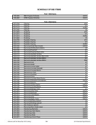
<strong>FDM</strong> <strong>19</strong>-<strong>10</strong>-25 Sample Proposal October 22, 2012<br />
The sample proposal for a bid contract includes the following:<br />
- Highway Work Proposal (Form DT1502) See example Attachment 25.1,<br />
- Special Provisions (see Section 15 of this chapter),<br />
- Additional Special Provisions (see <strong>FDM</strong> <strong>19</strong>-15-90) that are pertinent to the contract,<br />
- Contract language; including language that is appropriate to the funding source for the proposal.<br />
- Appropriate wage rates.<br />
- The Schedule of Items included in the contract.<br />
After PS&E submittal, if funding changes are necessary, contact the Proposal Management Engineer at<br />
(608) 266-3611. After the proposal is assembled (day of the Ad Meeting, see <strong>FDM</strong> <strong>19</strong>-1 Attachment 1.2), no<br />
funding changes will be allowed as contract language added to the proposal directly correlates to the proposal’s<br />
funding source(s).<br />
Form DT1502 is available in MS Word format at http://dotnet/consultants/stsp/index.shtm.<br />
25.1 Completing Form DT1502<br />
- To complete the Highway Work Proposal Form, DT1502, fill in the following fields:<br />
- County, State Project ID, Project Description, and Highway. Enter the project’s description exactly as it<br />
appears in FIIPS and on the plan’s title sheet. If there is more than one project in the proposal, use<br />
horizontal spaces to clearly delineate the different projects.<br />
- Proposal Guaranty Required. Obtain the amount from the table below:<br />
Proposal Guarantee<br />
Construction Cost Estimate* Proposal Guarantee<br />
0 - 75,000 $ 2,000<br />
75,000 - 150,000 $ 6,000<br />
150,000 - 500,000 $ 20,000<br />
500,000 - 1,000,000 $ 40,000<br />
1,000,000 - 5,000,000 $ 75,000<br />
> 5, 000,000 $<strong>10</strong>0,000<br />
* This amount does not include engineering and contingencies.<br />
- Bid Submittal Due, the letting date. Do not abbreviate the month; spell out the month’s complete<br />
name.<br />
- Contract Completion Time, the number of calendar days, working days, or the completion date of the<br />
contract (see <strong>FDM</strong> <strong>19</strong>-<strong>10</strong>-<strong>30</strong>); for example, Thirty (<strong>30</strong>) Working Days, Ninety (90) Calendar Days, or<br />
November <strong>10</strong>, 20<strong>10</strong>.<br />
- Type of Work. Indicate the major work classification(s) of the contract, e.g., grading, base aggregate<br />
dense, Structure (Number), concrete pavement, HMA pavement, pavement marking, permanent<br />
signing, traffic signals, lighting, ITS, and storm sewer.<br />
The BPD will complete the federal project ID field, and will mark whether there is federal oversight on the<br />
project.<br />
The sample proposals (contract) for LFA agreements are covered in Section 25 of this Chapter.<br />
LIST OF ATTACHMENTS<br />
Attachment 25.1 Sample of Completed DT1502 Form Highway Work Proposal<br />
Page 12
<strong>FDM</strong> <strong>19</strong>-<strong>10</strong> PS&E Transmittal and Composition<br />
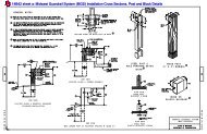
<strong>FDM</strong> <strong>19</strong>-<strong>10</strong>-<strong>30</strong> Contract Time for Completion (DT<strong>19</strong>23) October 22, 2012<br />
<strong>30</strong>.1 General<br />
A completed Contract Time for Completion (Form DT<strong>19</strong>23) is required for all bid contracts and negotiated<br />
agreements.<br />
An example is included as Attachment <strong>30</strong>.1.<br />
<strong>30</strong>.2 Contract Time<br />
The contract should be analyzed in sufficient detail to determine a reasonable contract time. Contract time can<br />
be set up on the basis of working days, calendar days, or by specifying a completion date. In any case, a<br />
minimum of four to six weeks is estimated between the letting date and contract execution.<br />
Calendar day. Every day shown on the calendar, Sundays and holidays included. This is one of the preferred<br />
methods of establishing contract time when an Interim Liquidated Damages provision is included in the contract.<br />
To determine contract time expressed in calendar days, first estimate the number of workdays needed to<br />
prosecute the contract work. To this add Saturdays, Sundays, Holidays, and the influence of anticipated weather<br />
conditions as expressed in terms of probable working days. (See Attachment <strong>30</strong>.2 to determine probable<br />
working days.)<br />
Contract time shall be rounded to the nearest five days. Contract time suspensions ordered by the engineer<br />
and/or the days required for certain excluded work operations are not included within this total.<br />
Working day. This is a calendar day, except for Saturdays, Sundays and specified legal holidays, on which<br />
weather and conditions not under the control of the contractor will permit construction operations to proceed for<br />
at least eight hours with the normal working force engaged in performing the controlling item of work which<br />
would be in progress at this time. The controlling item is that item which must be partially or wholly completed to<br />
permit progress essential to complete the contract within the number of working days allowed. See Standard<br />
Specification <strong>10</strong>8.12 for construction details related to working day contracts.<br />
The working days method is preferred for establishing contract time for a normal construction project. Working<br />
day contracts equitably provide for those projects where relatively minor weather changes greatly influence work<br />
progress, or where there are frequent delays occasioned by other contracts, material delivery, or operations<br />
beyond the contractor's effective control.<br />
Contract time shall be rounded to the nearest five days.<br />
Completion date. The calendar date shown in the proposal on or before which the work contemplated in the<br />
contract shall be completed. No time extension allowances are made for normal delays or lack of progress.<br />
A completion date is preferred when an Incentive/Disincentive provision is used in the contract.<br />
A completion date contract should be considered in any of the following situations:<br />
1. When stage construction contracts must closely follow one another to meet a desired open-to-traffic<br />
date.<br />
2. When the timing of a special event is the critical factor in determining the desired completion date.<br />
3. When the contract work is expected to extend over multiple construction seasons.<br />
4. When the Interim Liquidated Damages provision is included in the contract.<br />
Designers should avoid requiring unjustifiably high rates of operation progress through improper selection of an<br />
early completion date. The normal procedure is to select the completion date from a working day type time<br />
analysis, taking into consideration the desired reasons for specifying the use of a completion date.<br />
<strong>30</strong>.3 Factors Influencing Contract Time<br />
Holidays shall be New Years Day, Martin Luther King Jr. Day, Memorial Day, Independence Day, Labor Day,<br />
Thanksgiving Day, Christmas Eve Day, Christmas Day and New Year's Eve Day.<br />
Probable working days in a month are the possible weekdays available for work multiplied by a percentage<br />
factor based on past experience for the major construction operation being performed. A percentage factor chart<br />
is included as Attachment <strong>30</strong>.2 of this procedure. It may be used directly or with minor modification to reflect<br />
regional weather conditions. The possible working days in a month are the total number of calendar days minus<br />
any Saturdays, Sundays and holidays that occur during that month.<br />
Production Rates. The production rates should be tailored to meet the conditions of each individual contract.<br />
Page 13
<strong>FDM</strong> <strong>19</strong>-<strong>10</strong> PS&E Transmittal and Composition<br />
Consideration should be given to the size of work areas, time of year constructed, congestion due to traffic, etc.<br />
See Attachment <strong>30</strong>.3 for estimated average production rates.<br />
Utility and railroad adjustments are usually planned to occur prior to construction operations to avoid interfering<br />
with the contractor's construction schedule. Occasionally, utility or railroad facility adjustments must be<br />
performed during construction operations. If there is good reason to believe that these adjustments may delay<br />
the contractor, time should be added to the contract time for completion. The district utility or railroad coordinator<br />
should be consulted as necessary.<br />
Temporary structures. When a temporary structure is required to keep the highway open to traffic, a sufficient<br />
amount of time should be included in the contract time for the construction of the temporary structure. This time<br />
should be shown on the contract time chart.<br />
Curing and protection of concrete. Include the contract time required to ensure concrete is sufficiently cured and<br />
has developed adequate strength to support subsequent construction operations without damage to in-place<br />
work. Also include time required before bridge decks can be sealed.<br />
Exclusion From Contract Time Charge<br />
Operations excluded from the contract time charges are those occurring prior to and following the major<br />
operations of the contract, a brief list of these is as follows:<br />
1. Construction Staking, initial layout before grading work begins.<br />
2. Move-in of equipment by the contractor.<br />
3. Clearing, grubbing, stripping and subsequent final clean-up of aggregate pits or quarries, borrow or<br />
subbase pits.<br />
4. Delivery, installation and removal of temporary traffic control devices.<br />
5. Exploratory digging of test holes.<br />
6. Construction, maintenance and subsequent obliteration of access roads to pits or quarries.<br />
7. Setting up and dismantling of crushing, asphaltic or concrete batching or mixing plants.<br />
8. Preliminary blasting or crushing for test samples.<br />
9. Watering sod, when performed after completion of all sod replacement and all other construction work<br />
is completed. The <strong>10</strong>-day watering requirement remains in effect, however.<br />
<strong>10</strong>. The production of aggregate stockpiles when no other work is in progress nor has been ordered to<br />
start.<br />
11. Repairs to equipment performed at the work site prior to the start of work during official suspension or<br />
after contract work is completed.<br />
LIST OF ATTACHMENTS<br />
Attachment <strong>30</strong>.1 Sample of Form DT<strong>19</strong>23, Contract Time for Completion<br />
Attachment <strong>30</strong>.2 Percentage Factors for Probable Working Days<br />
Attachment <strong>30</strong>.3 Estimated Production Rates for Computing contract Time<br />
<strong>FDM</strong> <strong>19</strong>-<strong>10</strong>-35 Certificate of Right of Way (DT1899) July 28, 2011<br />
The FHWA has established rules and regulations that must be followed by state and local agencies when<br />
acquiring highway right of way where federal aid funds are used. A Certificate of Right of Way (form DT1899)<br />
shall always accompany the PS&E transmittal. Note: At the time of this writing, an additional step is being<br />
implemented on a trial basis where an exception report is being required at the time of the PS&E to try and<br />
address any issues that may prevent a project from meeting all requirements for advertisement and letting. See<br />
<strong>FDM</strong> <strong>19</strong>-1-3 for more about the project letting process.<br />
** When finished filling in the DT1899. Please convert to a PDF per instructions on the bottom of the form.<br />
35.1 Right-of-Way Clearance<br />
The status of ROW is reported using the Certificate of Right of Way (form DT1899). Attachment 35.1 shows a<br />
copy of this form with detailed instructions for completing. An electronic copy of this form is available from the<br />
DOTNET Real Estate Program Manual (REPM). WisDOT staff can reach the REPM/Forms page through the<br />
Page 14
<strong>FDM</strong> <strong>19</strong>-<strong>10</strong> PS&E Transmittal and Composition<br />
DOTNET at: http://dotnet/dtid_real_estate/repm/repm.htm. Consultants can reach the REPM/Forms page by<br />
first logging on to the extranet and then going to:<br />
https://trust.dot.state.wi.us/extntgtwy/dtid_real_estate/repm/repm.htm.<br />
The top half of this form (see items marked #1 – 17 on Attachment 35.1) is always completed by the<br />
organization that is designing the project (either the region or the consultant); however, only WisDOT is<br />
authorized to verify and approve the information given. Further processing of this form depends upon the project<br />
circumstances.<br />
35.1.1 No New ROW Required<br />
If there is no new land interest being acquired (either permanent or temporary), then the regional project<br />
development unit representative should check the appropriate box and type their name in Section 15. Only<br />
WisDOT is authorized to verify and approve the information given on the certification. The form should then be<br />
added to the PS&E package.<br />
35.1.2 New ROW Is Required<br />
If the project does require the acquisition of new land interests (either permanent or temporary) then the regional<br />
project development unit representative should check the appropriate box and type their name in Section 15.<br />
Only WisDOT is authorized to verify and approve the information given on the certification. The form should then<br />
be sent to the regional technical services real estate unit for completion of Sections 16 - 21. The responsible<br />
regional real estate representative will fill in their name in Section 21. Only WisDOT is authorized to verify and<br />
approve the information given on the certification. When all sections have been completed the form should be<br />
added to the PS&E on-line transmittals in accordance with <strong>FDM</strong> <strong>19</strong>-<strong>10</strong>-1.<br />
LIST OF ATTACHMENTS<br />
Attachment 35.1 Certificate of Right of Way<br />
<strong>FDM</strong> <strong>19</strong>-<strong>10</strong>-40 Utilities Status Report (DT<strong>10</strong>80) July 28, 2011<br />
The information contained in the USR (Form DT<strong>10</strong>80) provides data relative to utility facilities within the project<br />
and the status of utility parcels and agreements. See <strong>FDM</strong> 18-<strong>10</strong>-40 for guidance on creating a USR and a<br />
sample of one.<br />
** When finished filling in the DT<strong>10</strong>80. Please convert to a PDF per instructions on the bottom of the form.<br />
40.1 Utility Clearance<br />
The utilities status is reported by the region. The status of non-parcel utility facilities should also be included.<br />
Where utility adjustments or relocations have been performed prior to the PS&E. transmittal date, the special<br />
provisions should contain current information.<br />
<strong>FDM</strong> <strong>19</strong>-<strong>10</strong>-43 Digital Data Exchange and Project Data Awareness June <strong>19</strong>, 2013<br />
43.1 General<br />
This procedure describes the requirements for submitting digital highway project data, the procedure for<br />
archiving the project data and for creating the contractor staking packet (detailed in CMM 7-<strong>10</strong>.3) and archiving<br />
the project. All questions about the content of this procedure should be directed to one of the Methods<br />
Development Engineers at dotcaesupport@dot.wi.<strong>gov</strong> .<br />
43.1.1 Application<br />
The requirements of this procedure apply only to projects on the state trunk highway system. For consultantdesigned<br />
projects, these requirements apply to two-party contracts only.<br />
43.1.2 AutoCAD Civil 3D Mandate Notification<br />
The use of AutoCAD Civil 3D software and file formats native to it will be required on most highway projects.<br />
Further information is included in Attachment 43.7.<br />
43.2 Introduction<br />
Digital Data Exchange provides a way to transfer highway project data, using standard formats, which allows the<br />
reuse of information in engineering software, versus the recreation of information.<br />
Page 15
<strong>FDM</strong> <strong>19</strong>-<strong>10</strong> PS&E Transmittal and Composition<br />
43.3 Digital Data Submittal<br />
Regions can comply with the requirements of this procedure (i.e., creating the contractor staking packet and<br />
project archive) by placing the appropriate electronic data files in the CADDS electronic filing cabinet at the time<br />
of PS&E submittal. No physical document need be sent to central office as part of the P. S. & E. submittal.<br />
Consultants shall submit a preliminary list of electronic data files to the region when they submit their PS&E.<br />
This list will identify the files they intend to submit after the PS&E is checked and corrected. This file list should<br />
use the same format as the meta-data document that must accompany the actual file submittal.<br />
The region must provide feedback to the consultant on any additional files that are needed but were not shown<br />
on the preliminary list. After the PS&E has been reviewed and corrected, consultants shall submit the electronic<br />
project data files on a read-only compact disc (CD) directly to the regions.<br />
All data types required by this procedure shall be on a single CD or DVD. The consultant must maintain a copy<br />
of the data that is submitted. The consultant must check the data for accuracy and certify it to be correct before<br />
delivery to the region. The disc shall also contain a meta-data document that lists all files contained on the disc.<br />
An electronic copy of the meta-data document template can be downloaded from the Department’s ftp site at<br />
ftp://ftp.dot.wi.<strong>gov</strong>/dtsd/bpd/methods/caice. A copy of this template is shown in Attachment 43.1.<br />
Regions shall not forward the consultant project data disc to central office. Instead, the region shall perform the<br />
file check-in process by verifying that the necessary data is on the CD and entering the project data files into the<br />
CADDS electronic filing cabinet.<br />
43.4 File Formats<br />
43.4.1 MicroStation DGN Specifications and Parameters<br />
All files submitted as DGN format shall be fully compatible with MicroStation v8 2004 or earlier. All design files<br />
must be 2D unless explicitly requested otherwise. The graphical data provided by the DOT may be in<br />
MicroStation version J7.1 or version 8 DGN format.<br />
The compilation of photogrammetric mapping and DTM data shall be in MicroStation 3D files. These files shall<br />
be converted to 2D and the DTM data shall be stripped from the files to deliver the mapping data for design.<br />
Design file working units shall be 1:<strong>10</strong>00:1. For English-based plans the master unit is the survey foot and the<br />
sub unit is 0.001 ft.<br />
The global origin (0,0) of design files shall be at x = 0, y = 0, z = 2147483.648 for MicroStation files. The<br />
graphical data must be coordinate correct in the applicable coordinate system drawn at a 1 to 1 scale. This does<br />
not apply to non-geographical drawings such as typical sections, standard details and cross section sheets.<br />
Project design files, as noted elsewhere in this manual, shall be prepared using ground level dimensions.<br />
The use of reference files is preferred unless explicitly requested otherwise. All files used as reference files shall<br />
be provided and documented. Each MicroStation V8 design file shall contain one model per design file. Design<br />
history shall not be enabled.<br />
43.4.2 AutoCAD Civil 3D DWG Specifications and Parameters<br />
All files submitted as Civil 3D DWG shall be fully compatible with AutoCAD Civil 3D 2012 or earlier.<br />
43.5 Categories of Digital Data Exchange<br />
There are eleven categories of information for which digital data standards have been set. The eleven<br />
categories and a description of the data contained in each category are described below.<br />
Page 16
1.<br />
2.<br />
3.<br />
Field Control<br />
Data<br />
Reference Line<br />
Data<br />
Right-of-Way<br />
Monumentation<br />
Data<br />
4. Design Profile<br />
Data<br />
5. Existing and<br />
Proposed Cross<br />
Section Data<br />
<strong>FDM</strong> <strong>19</strong>-<strong>10</strong> PS&E Transmittal and Composition<br />
Data in this category are used to establish survey control in the field. Field control points are<br />
physical points collected in the field, not points created by a designer. Data must be<br />
provided in the coordinate system specified for the project. Points to include are those with<br />
feature codes 1 of:<br />
SEC Section corner monument<br />
CP Control point<br />
MON Monument<br />
QTR Quarter corner monument<br />
SECC Section quarter corner graphic<br />
SECH Half section corner graphic<br />
SIXT Sixteenth corner<br />
GPS GPS monument<br />
USGS USGS monument<br />
HTGT Horizontal target (X,Y)<br />
TGT Total target (X,Y,Z)<br />
NGS NGS station/monument<br />
RW Existing right-of-way break point<br />
MEAN Meander corner monument<br />
BM Bench Mark<br />
This category includes all mainline and side road reference line data, and the project<br />
control necessary to establish such reference lines. This category also includes<br />
pavement chains and other miscellaneous chain information, as specified for the<br />
project.<br />
This category includes all existing and proposed right-of-way chains and points to be staked<br />
including those considered to be Fees, PLE or TLE locations. Data to include are those with<br />
feature codes of:<br />
PLE Permanent limited easement<br />
TLE Temporary limited easement<br />
RW Existing right-of-way break point<br />
PRW Proposed right-of-way break point<br />
EASE Easement<br />
RDE Restricted development easement<br />
SE Scenic easement<br />
This category includes profiles of any reference lines, driveways and ditches, as specified for<br />
the project.<br />
This category includes cross section data of the existing ground and proposed finished<br />
ground surfaces. Surface feature names in the cross section files must follow department<br />
standards. All cross section data submitted must have corresponding reference line<br />
information submitted as well.<br />
6. DTM Data This category includes existing surface data to be used with engineering tools.<br />
7. Superelevation<br />
Data<br />
8. Existing<br />
Topographic<br />
Data - Utilities<br />
9. Existing<br />
Topographic<br />
Data - Other<br />
<strong>10</strong>. Other Survey<br />
Data<br />
11. Graphical<br />
Information<br />
This category includes information on locations of the superelevation transition points along<br />
an alignment. The minimum number of transition points, which must be included, are the<br />
beginning and ending of normal crown, reverse crown, and the beginning and ending of full<br />
superelevation.<br />
This category includes point and chain information pertaining to utilities such as gas,<br />
telephone, and storm sewer. WisDOT standard feature codes must be used for the data in<br />
this category. Attributes of Ground or Feature will be appropriately assigned if valid WisDOT<br />
feature codes, as found in the <strong>Wisconsin</strong> Standard Feature Table, are used.<br />
This category includes point and chain information pertaining to topographic information,<br />
other than utilities. This includes but is not limited to, fences, tree lines, and waterways.<br />
This category of data is for those survey items not included in any of the other categories<br />
Information in this category is contained in MicroStation DGN files or AutoCAD Civil 3D<br />
DWG files. It contains both DGN/DWG files used to create plan sheets, and DGN/DWG files<br />
which contain the plan sheets themselves.<br />
43.6 Digital Data Formats<br />
For each of the eleven data categories, standard digital formats have been established. The acceptable formats<br />
for each category are described below. Note that any standard format in the various categories must be<br />
accepted. Unless a mutual agreement has been made between the consulting firm performing the project work<br />
and the appropriate region office, a preferred format cannot be mandated.<br />
1 A list of feature codes can be downloaded from the following web site:<br />
www.dot.state.wi.us/dtid/bhd/rds_standards.html#CAiCE<br />
Page 17
<strong>FDM</strong> <strong>19</strong>-<strong>10</strong> PS&E Transmittal and Composition<br />
Field Control Data - SDMS Control (CTL) file format with a hard copy tie sheet noting locations (unless<br />
noted on plan).<br />
- CAiCE Project File (KCP) format with a hard copy noting location of ties.<br />
- AutoCAD Civil 3D DWG file using Civil 3D points.<br />
Reference Line Data - SDMS Alignment File (ALI) format, version 3.4 - SDMS Alignment File formats<br />
previous to version 3.4 will not be accepted.<br />
- CAiCE Project File (KCP) format<br />
- CAiCE KCM File format<br />
- CAiCE Horizontal Alignment (HA#) format<br />
- CAiCE Describe Chains Report (to be included in contractor staking packet, in<br />
addition to above items)<br />
- AutoCAD Civil 3D DWG file using centerline alignments<br />
- SDMS Control File (CTL) format submitted along with a full size (22” x 34”) plat<br />
Right-of-Way<br />
noting point locations - this format must be provided when transferring data to be<br />
Monumentation Data<br />
used in survey<br />
- CAiCE KCM file format<br />
- AutoCAD Civil 3D DWG file using Civil 3D points<br />
- CAiCE Project File (KCP) format<br />
Design Profile Data<br />
- SDMS Profile File (PRO) format<br />
- AutoCAD Civil 3D DWG file using profiles. These shall be in the same file as the<br />
associated alignment.<br />
- CAiCE Cross Section (EAR) file along with an SDMS ALI file<br />
Existing and<br />
Proposed Cross<br />
Section Data<br />
- SDMS Calculated File (CAL) format with XSE task, along with an SDMS<br />
Alignment File (ALI) format (SDMS version 3.4 or higher)<br />
- Generic Station-Offset-Elevation file (example format provided in this chapter)<br />
along with an SDMS Alignment File (ALI) format (SDMS version 3.4 or higher)<br />
- AutoCAD Civil 3D DWG file using alignments, surfaces and section view groups.<br />
- Full set of CAiCE surface files<br />
DTM Data<br />
- CAiCE SRV file format<br />
- SDMS Calculated File (CAL) format with RTO or COM task. XX, YY, and ZZ<br />
values for points, and point connectivity for all discontinuities must be provided in<br />
the file. Point connectivity for all discontinuity lines provided using FG number or<br />
OD number ONLY.<br />
- AutoCAD Civil 3D DWG file using Surfaces<br />
Superelevation Data - SDMS Superelevation File (SUP) format<br />
- AutoCAD Civil 3D DWG file using alignments with superelevation.<br />
Existing Topographic<br />
- SDMS CAL file format using WisDOT standard feature codes with point<br />
Data - Utilities<br />
connectivity for all discontinuity lines provided using FG number or OD number<br />
ONLY.<br />
- MicroStation DGN file<br />
- AutoCAD Civil 3D DWG file<br />
Existing Topographic<br />
- SDMS CAL file format using WisDOT standard feature codes with point<br />
Data - Other<br />
connectivity for all discontinuity lines provided using FG number or OD number<br />
ONLY.<br />
- MicroStation DGN file<br />
- AutoCAD Civil 3D DWG file<br />
Other Survey Data CAiCE Project (KCP) File Format<br />
- CAiCE KCM file format<br />
- CAiCE SRV file format<br />
- MicroStation DGN file<br />
- AutoCAD Civil 3D DWG file using Civil 3D points and 3D polylines<br />
- AutoCAD Civil 3D DWG file using points and figures<br />
- SDMS Calculated File (CAL) format with RTO or COM task. XX, YY, and ZZ<br />
values for points, and point connectivity for all discontinuities must be provided in<br />
the file. Point connectivity for all discontinuity lines provided using FG number or<br />
OD number ONLY.<br />
Page 18
<strong>FDM</strong> <strong>19</strong>-<strong>10</strong> PS&E Transmittal and Composition<br />
Graphical Information Acceptable format is the MicroStation DGN file, where the files submitted must follow all<br />
CADD standards outlined in Chapter 15 of the <strong>FDM</strong> including:<br />
- File must be a 2-D file<br />
- Usage of WisDOT user defined line styles and font libraries<br />
- Data must be located in applicable coordinates and be coordinate correct.<br />
- Usage of shared cells is not allowed.<br />
- The use of reference files is allowed, unless explicitly requested otherwise. All<br />
reference files attached must be provided and documented.<br />
Another acceptable format is the AutoCAD Civil 3D DWG file, where the files submitted must<br />
follow CADD standards outlined in Chapter 15 of the <strong>FDM</strong> including:<br />
- Usage of WisDOT line types, fonts, layers and other display characteristics.<br />
- Data must be located in applicable coordinates and be coordinate correct.<br />
- The use of x-references is allowed, unless explicitly requested otherwise. All xreference<br />
files attached must be provided and documented.<br />
43.6 Standard Formats Which Are ASCII Formats<br />
Each digital format that is ASCII is described here. In addition, for all SDMS format file types listed, further<br />
information on the specific formats can be found in the AASHTOWare SDMS Technical Data Guide prepared by<br />
AASHTO. A copy of this guide is available online at ftp://ftp.aashtoware.org/products/sdms from AASHTO.<br />
43.6.1 CAiCE SRV File Format<br />
The general format for point information in a CAiCE SRV file is:<br />
<br />
Example, 140542.690 42415.412 201.653 XYZ PT25477<br />
Survey chain or discontinuity line information stored in a CAiCE SRV file begins with the line:<br />
BEGIN <br />
Example, BEGIN CH1345 DL<br />
For each point that comprises the survey chain/discontinuity line, an entry is made in the CAiCE SRV file of the<br />
format<br />
-1 <br />
To indicate the end of the survey chain/discontinuity line the word END must appear.<br />
An example of a complete survey chain/discontinuity line entry is shown below:<br />
BEGIN CH1345 DL<br />
140851.738 42345.465 201.7<strong>30</strong> -1 PT264<strong>19</strong><br />
140847.835 42347.467 201.759 -1 PT26420<br />
140844.927 42350.116 201.744 -1 PT26421<br />
END<br />
A CAiCE SRV file with both point and survey chain/discontinuity line information example is shown here.<br />
140566.672 42414.609 201.376 XYZ PT25480<br />
140574.670 42414.336 201.376 XYZ PT25481<br />
140582.666 42414.065 201.361 XYZ PT25482<br />
BEGIN CH1345 DL<br />
140851.738 42345.465 201.7<strong>30</strong> -1 PT264<strong>19</strong><br />
140847.835 42347.467 201.759 -1 PT26420<br />
140844.927 42350.116 201.744 -1 PT26421<br />
END<br />
140590.662 42413.796 201.237 XYZ PT25483<br />
140598.653 42413.528 201.339 XYZ PT25484<br />
Include metadata at the top of a CAiCE SRV file to define information related to the coordinates in the file. Any<br />
format can be used for the metadata as long as each line is preceded by the “#” symbol. The example shown<br />
below is used at WisDOT.<br />
#AC:PR<br />
#ID:0000-00-00<br />
#CL:PROJECT<br />
#PR:ANY TOWN - ANY TOWN<br />
#HY:USH00<br />
Page <strong>19</strong>
<strong>FDM</strong> <strong>19</strong>-<strong>10</strong> PS&E Transmittal and Composition<br />
#CO:COUNTY<br />
#HD:NAD 83 (<strong>19</strong>91)<br />
#CS:WCCS<br />
#ZN:4803<br />
#VD:NGVD 29<br />
#HT:ORTHO<br />
#UL:M<br />
#VR:CONMET/MANUAL DATA ENTRY<br />
#RE:SURVEYOR - DISTRICT 0 TOWN<br />
#DT:<strong>10</strong>/21/94<br />
43.6.2 CAiCE Project File (KCP)<br />
The CAiCE Project File format has many components to it. Any given CAiCE Project File may contain one or<br />
more of these components. The attributes of each component are given in Attachment 43.2, as well as an<br />
example CAiCE Project File below.<br />
A CAiCE Project File (KCP) that contains one survey point and one survey chain is shown here.<br />
*** SURVEY POINT ***<br />
PN: A1<br />
XC: 2474935.11<strong>30</strong>84<br />
YC: 359280.650779<br />
ZC: -99999.900000<br />
ZN: 1<br />
JN: -1<br />
AT: G<br />
GM: P<br />
FC: DTRE<br />
AN: 0<br />
*** SURVEY CHAIN ***<br />
CN: EB1<br />
ST: 0.000000<br />
ZN: 1<br />
JN: 4<br />
AT: G<br />
FC: EB<br />
AN: 0<br />
CP: EB<strong>10</strong>08-<strong>10</strong>25<br />
43.6.3 Generic Station-Offset-Elevation File<br />
Station-Offset-Elevation files can be created in many ways, but the generic format that will be accepted as part<br />
of this data standard lists the for each point on a cross section. An example<br />
SOE file is given here.<br />
<strong>10</strong>+00.000 -2.742 663.874<br />
<strong>10</strong>+00.000 1.178 663.872<br />
<strong>10</strong>+00.000 12.266 664.240<br />
<strong>10</strong>+00.000 16.493 664.268<br />
<strong>10</strong>+00.000 63.048 662.855<br />
<strong>10</strong>+00.000 65.550 662.745<br />
<strong>10</strong>+00.000 72.809 661.907<br />
11+00.000 -37.280 660.425<br />
11+00.000 -25.218 660.502<br />
SDMS control file information defines horizontal control points, vertical benchmark points and calculated points<br />
to be staked. The basic structure of this SDMS format is given below.<br />
Data Item Description<br />
AC:xx Any activity data item marking the beginning of a control point.<br />
PN:xx Unique Point Number – no alpha characters allowed<br />
YC:xxxxxxx.xxx Northing (Y coordinate)<br />
XC:xxxxxxx.xxx Easting (X coordinate)<br />
ZC:xxxxxxx.xxx Elevation (Z coordinate)<br />
PD:control point Point Description<br />
… Other data items<br />
The first data item of a control point must be the activity data item. Other data items can be in any order.<br />
43.6.4 SDMS Alignment File (ALI) Format<br />
SDMS alignment files contain highway alignment information. Two different ALI definitions exist; however, only<br />
the PI definition of the ALI format will be accepted. This definition precludes alignments with station equations,<br />
compound curves, and PC/PTspirals that cannot be handled by the SDMS PC/PT defined alignments. The basic<br />
structure of the SDMS ALI format is given below.<br />
Page 20
<strong>FDM</strong> <strong>19</strong>-<strong>10</strong> PS&E Transmittal and Composition<br />
Data Item Description<br />
TY:PI Indicates that the PI definition is used to define the alignment and is required. If this data<br />
item is omitted, the PC/PT definition is assumed.<br />
AC:PR Project header activity in which valid SDMS tags are used to detail metadata such as<br />
horizontal and vertical datums, coordinate systems, zones, units of length, etc.<br />
AC:EQ Station equations are optional, but if provided define the location of a station equation<br />
point. All equations must be listed in the order they appear in the alignment and cannot<br />
be located on a curve or spiral element.<br />
PN:# Identifies the point used for the equation point (Optional).<br />
SB:###+## Defines the station back of the equation point (Optional).<br />
ST:###+## Defines the station ahead of the equation point (Optional).<br />
PD:, CM:, FE: Point description, comment, feature code. All other tags in the shot are ignored, but can<br />
be included for documentation purposes.<br />
AC:xx Alignment description begins here.<br />
PN:nnn Point number (Optional)<br />
ST:nn+nn,n Station value at the beginning of the alignment.<br />
XC:xxxxx.xxx<br />
YC:xxxxx.xxx<br />
The origin point of the alignment (required)<br />
ZC: The elevation (Optional).<br />
SI:xx SI:PI is the point where two tangent lines meet. It defines the circle arc<br />
segment. A shot ID should be entered for each segment.<br />
AC:xx Activity for the next segment in the alignment.<br />
PN:nnn Point number (Optional)<br />
ST:nn+nn,n The stationing of each intermediate PI for the horizontal alignment being<br />
defined (Optional).<br />
XC:xxxxx.xxx<br />
Defines the X and Y coordinates of the starting point of the alignment and is<br />
YC:xxxxx.xxx<br />
required.<br />
ZC:xxxxx.xxx The elevation (Optional).<br />
RA:nnn Defines the radius of a curve.<br />
PD:, CM: Point description, comment. All other tags in the shot are ignored, but can be<br />
included for documentation purposes.<br />
Subsequent segments repeat as necessary, beginning with AC:xx<br />
43.6.5 SDMS Vertical Alignment File (PRO) format<br />
SDMS Vertical Alignment files define VPI points by station and elevation. The information in this file is used in<br />
conjunction with highway alignment data. Symmetrical and assymetrical vertical curves at a VPI are specified by<br />
defining the length of the parabolic curve along the station axis. The first and last VPI cannot have vertical<br />
curves. The basic structure of the SDMS PRO format is given below.<br />
AC:PR Project header activity in which valid SDMS tags are used to detail metadata such as<br />
horizontal and vertical datums, coordinate systems, zones, units of length, etc.<br />
AC:EQ Station equations are optional, but if provided define the location of a station equation point.<br />
PN:# Identifies the point used for the equation point (optional).<br />
SB:###+## Defines the station back of the equation.<br />
ST:###+## Defines the station ahead of the equation.<br />
PD:, CM:, FE: Point Description, Comment and Feature Code.<br />
AC:xx Alignment description.<br />
PN:nnn Point number, which is optional.<br />
ST:nn+nn Stationing value at the beginning of the alignment.<br />
XC:xxxxxx.xxx X coordinate of beginning point of the profile.<br />
YC:xxxxxx.xxx Y coordinate for the beginning point of the profile.<br />
ZC:xxxxxx.xxx The elevation of the beginning point of the profile.<br />
SI:VPI VPI for the point at the beginning and end of the profile and where two vertical slope lines<br />
meet.<br />
L1:xxxx Defines the length of the vertical curve from the VPC to the VPI along the station axis.<br />
L2:xxxx Defines the length of the vertical curve from the VPI to the VPT along the station axis. Value<br />
will equal L1 with symmetric curves.<br />
AC:xx The description of the next segment begins here. Use any activity data item except AC:PR<br />
or EQ. REQUIRED.<br />
PN:nnn Point number (optional)<br />
ST:nn+nn,n Stationing of second VPI of the profile.<br />
XC:xxxxxx.xxx X coordinate of the second VPI on the profile.<br />
YC:xxxxxx.xxx Y coordinate of the second VPI on the profile.<br />
Page 21
<strong>FDM</strong> <strong>19</strong>-<strong>10</strong> PS&E Transmittal and Composition<br />
ZC:xxxxxx.xxx The elevation of the second VPI on the profile.<br />
SI:VPI Same as above.<br />
L1:xxxx Same as above.<br />
L2:xxxx Same as above.<br />
AC: Repeat as above to define each VPI in the profile.<br />
43.6.6 SDMS Superelevation File (SUP) format<br />
An SDMS Superelevation file defines the slopes to be used at a station and elevation to determine the left and<br />
right side slopes of the design section at any station along the alignment. The basic structure of this SDMS<br />
format is given below.<br />
Data Item Description<br />
AC:PR Project header activity in which valid SDMS tags are used to detail metadata such as<br />
horizontal and vertical datums, coordinate systems, zones, units of length, etc.<br />
AC:EQ Station equations are optional, but if provided define the location of a station equation point.<br />
PN:nnn Point number used for the equation point.<br />
SB:###+## Station back of the equation.<br />
ST:###+## Station ahead of the equation<br />
PD:; CM:; FE: Point description, comments and feature codes.<br />
AC:xx Alignment description begins here.<br />
ST:nn+nn Beginning stationing value at the beginning or within the stationing defined by the alignment.<br />
E1:xxxx Superelevation slope rate on the left side (0.02).<br />
E2:xxxx Superelevation slope rate on the right side (0.02).<br />
PD:, CM: Can be used to say what the transition is as in CM:End Normal Crown.<br />
AC:xx New activity is used for each change in superelevation transition being defined.<br />
ST:nn+nn,n Stationing value for the transition being defined.<br />
E1:xxxx Superelevation slope rate on the left side (0.02).<br />
E2:xxxx Superelevation slope rate on the right side (0.02).<br />
PD:, CM: Can be used to say what the transition is as in CM:Begin Full Super.<br />
AC: Repeat activities as required to define superelevation transitions.<br />
43.7 SDMS Calculated File Formats and General Rules of Standard Tasks<br />
Many of the standard file formats listed in this document are SDMS Calculated (CAL) file formats using various<br />
SDMS tasks and activities. The guidance given here can be supplemented by referring to the more complete<br />
descriptions outlined in the AASHTOWare SDMS Data Structure Overview document.<br />
Only the XSE (Cross Section Task), RTO (Radial Topography Task) and the COM (Combined Task) tasks are<br />
considered standard for purposes of digital data transfer from consultant to WisDOT. Not all options available for<br />
each task will be accepted as part of the standard. The exceptions and general rules for the format allowable for<br />
each task are outlined below.<br />
1. Only certain activities are allowed to be used under a given task. Refer to the TASK.TGS file and the<br />
AASHTOWare SDMS Data Structure Overview document for the definitions of what restrictions exist<br />
for each task.<br />
2. Only two SDMS tags are allowable in WisDOT standard SDMS Calculated files to define connectivity.<br />
The first is OD, which stands for Origin/Destination and it defines the PN to which the PN of the<br />
current activity is to be connected. The second is FG, which is the Figure Number. Using this method,<br />
each chain is assigned a unique figure number and every measured point that is part of a chain is<br />
tagged with the figure number of that chain. Rules for using the OD or FG method can be found in the<br />
AASHTOWare SDMS Data Structure Overview document. Currently, the Chain and Taping Activities<br />
are not part of the data standards defined here, but may be implemented at a later date.<br />
3. The RTO task allows one or more radial sideshots to be taken from one or more occupied stations.<br />
The required and optional activities and example CAL files using RTO task can be found in the<br />
AASHTOWare SDMS Data Structure Overview document.<br />
4. The TRA task allows for control traversing and trigonometric leveling. The required and optional<br />
activities and an example CAL file using the TRA task can be found in the AASHTOWare SDMS Data<br />
Structure Overview document.<br />
5. The COM task allows for control traversing, trigonometric leveling and simultaneous collection of<br />
sideshots. The required and optional activities and an example CAL file using the COM task can be<br />
found in the AASHTOWare SDMS Data Structure Overview document.<br />
6. The XSE task is used to define station, offset and elevation values for points located along an<br />
alignment. The required and optional activities and an example CAL file using the XSE task can be<br />
Page 22
<strong>FDM</strong> <strong>19</strong>-<strong>10</strong> PS&E Transmittal and Composition<br />
found in the AASHTOWare SDMS Data Structure Overview document.<br />
7. For survey data, the CAL file must contain measurement data. If data was not collected using SDMS<br />
software, the raw survey data file must also be included.<br />
Required Header Information for All SDMS File Formats<br />
All SDMS files submitted, regardless of the task, must contain the following header information:<br />
AC:PR<br />
ID:(8 character project ID 0000-00-00)<br />
PR:(from-to)<br />
HY:(highway designation)<br />
CO:(county name)<br />
DT:(mm/dd/yy)<br />
CM:(Select one) METRIC or ENGLISH<br />
UL:(Unit of Length- Select one) F or M<br />
CM:--HORIZONTAL INFORMATION-<br />
CM:(Select one)GRID or GROUND<br />
CF:1.00<br />
HD:(Hz datum- Select one) NAD 83(91) or NAD 27 or NAD 83(97)<br />
CS:(Value for Coordinate System such as WSPCS, WCCS, ASSUMED)<br />
ZN:(Zone- State 48## or County 92##)<br />
CM:--VERTICAL INFORMATION---<br />
VD:(Vert Datum- Select one) NGVD 29 or NAVD88<br />
HT:(ORTHOmetric vs. ELLIPsoid)<br />
For SDMS Cross Section files, the following additional header line must also be included:<br />
CM:Cross section limits ### TO ###<br />
43.8 Guidelines on Data Requirements by Project Type<br />
The following guidelines have been established so that region personnel writing consultant contracts can<br />
determine what type of digital data is needed for each specific consultant project.<br />
Each highway improvement project is unique, but most can be defined by one of the eight general categories<br />
listed below.<br />
1. Bridge Rehabilitation<br />
2. Bridge Replacement<br />
3. SHRM<br />
4. Resurface<br />
5. Pavement Replacement<br />
6. Reconditioning<br />
7. Reconstruction<br />
8. Expansions and Majors<br />
Each project has its own unique digital data needs. Therefore, digital data requirements should ultimately be<br />
determined on a project-by-project basis during project scoping. Only that data which is anticipated to be<br />
needed later should be requested so as not to detract from the intent of the requirement.<br />
The table below lists recommendations for data to be requested for each project type.<br />
Table 43.1 Recommended Electronic Project Data by Project Type<br />
Bridge<br />
Rehab.<br />
New /<br />
Repl.<br />
Bridge<br />
Field Control<br />
Data<br />
Reference Line<br />
X X<br />
Information X X<br />
Right of Way X<br />
SHRM Resurf. Pav’t<br />
Repl.<br />
X<br />
X<br />
X<br />
X<br />
Recond. Reconst. Expansion<br />
&<br />
Majors<br />
X<br />
X<br />
X<br />
X<br />
X<br />
X<br />
Page 23
Monumentation<br />
Design Profile<br />
New<br />
Only<br />
Information<br />
Existing &<br />
X X<br />
Proposed Cross<br />
Sections<br />
Existing Surface<br />
X X<br />
Data<br />
X X<br />
Superelevation<br />
X<br />
Information<br />
Existing<br />
Topographics<br />
Other Survey<br />
Data<br />
New<br />
Only<br />
Graphic Files X<br />
New<br />
Only<br />
<strong>FDM</strong> <strong>19</strong>-<strong>10</strong> PS&E Transmittal and Composition<br />
X<br />
X<br />
X<br />
X X X<br />
In the category of Other Survey Data, no recommendation on when to request this data is given in the table.<br />
This data category is used only when required survey information does not fall into any of the other categories,<br />
which is not generally predictable.<br />
It should be assumed that all graphical files needed to recreate the entire plan set are required on projects<br />
where graphical files are requested. Individual contracts may specify less Graphical Information when<br />
warranted.<br />
On projects where earthwork is paid lump sum, or if a job has less than <strong>10</strong> cross sections, a graphical<br />
representation of the proposed cross section may be sufficient. However, it is recommended that all Pavement<br />
Replacement and Reconditioning projects require one of the electronic cross section data formats given.<br />
43.9 Cost of Producing Electronic Data<br />
The cost of producing the Electronic Data will depend on the number of categories of data that are required. The<br />
required data depends on the type of project. A summary of time to produce files based on project type is shown<br />
in the table below. The times given include the time necessary to fill in the meta-data document pertaining to<br />
that data<br />
Project Type Est. Time (hours)<br />
Bridge Rehabilitation 1.0<br />
New/Replacement Bridge 1.5<br />
SHRM 0.5<br />
Resurface 0.5<br />
Pavement Replacement 2.0<br />
Reconditioning 3.0<br />
Reconstruction 7.5<br />
Expansion and Majors 8.0<br />
When requesting data, it is not acceptable to require one specific formatted file for a data type requested. All<br />
acceptable formats given for that data type as given in this chapter must be allowed to provide for reasonable<br />
adherence to the standards by the consultant community.<br />
43.<strong>10</strong> Electronic Project Data Confirmation<br />
After receiving electronic project data from a consultant, this data must be confirmed by personnel at the<br />
appropriate region. This confirmation involves verification that the formats of the files sent follow the standard<br />
formats outlined in this procedure. The confirmation does not imply that the electronic data received matches<br />
the information shown on the plan submitted as part of the PS&E, nor does it verify that the design is valid and<br />
follows design standards set by the Department. The confirmation does not release the consultant from<br />
responsibilities related to the constructability and validity of the design. The confirmation of electronic project<br />
data must take place within a month of receipt of the data from the consultant.<br />
After the data has been received and verified, a letter confirming the receipt and acceptance of this data will be<br />
sent to the consultant by the appropriate region. A copy of the confirmation checklist is shown in Attachment<br />
43.3.<br />
X<br />
X<br />
X<br />
X<br />
X<br />
X<br />
X<br />
X<br />
X<br />
X<br />
X<br />
X<br />
X<br />
X<br />
X<br />
X<br />
X<br />
X<br />
X<br />
X<br />
X<br />
Page 24
<strong>FDM</strong> <strong>19</strong>-<strong>10</strong> PS&E Transmittal and Composition<br />
43.11 Contractor Staking Packet<br />
The region assigned personnel or consultant designer should create a Contractor Staking Packet with the files<br />
received from a consultant or project data developed by the department. To create this packet a CD should be<br />
created with the electronic files/paper copies for the staking contractor’s use when the project is being built. For<br />
specific files and forms needed for packet see CMM 7-<strong>10</strong>.3 in the department’s Construction and Materials<br />
Manual.<br />
43.12 Project Archive<br />
Once electronic project data has been submitted, it is then the responsibility of the Department to store the data<br />
in a project directory in the CADDS Filing Cabinet where it can later be checked out for use by Department<br />
personnel working on that project.<br />
Upon receipt of electronic project data from consultants, the following procedure should be followed to validate<br />
and archive the data. The procedures outlined in Attachment 43.6 are performed by assigned personnel in the<br />
appropriate region.<br />
LIST OF ATTACHMENTS<br />
Attachment 43.1 Metadata Sheet for Project ID<br />
Attachment 43.2 CAICE Project File Component Attributes<br />
Attachment 43.3 Consultant Data Check-In Form<br />
Attachment 43.4 Format-Report on Alignment/Reference Line Details<br />
Attachment 43.5 Slope Stake Report Example<br />
Attachment 43.6 Project Archive<br />
Attachment 43.7 Civil 3D Specific Design Deliverable Requirements<br />
<strong>FDM</strong> <strong>19</strong>-<strong>10</strong>-45 Changes to Consultant Plans February 25, 2011<br />
45.1 Purpose<br />
To establish procedural guidelines to be followed when changes are required to plans developed by consultants.<br />
The guidelines are intended to assure that all inputs are recognized and considered and that all parties are<br />
appropriately involved and have necessary documentation available to them.<br />
45.2 Statement of Problem<br />
Consultants who have designed plans for WisDOT administered projects are concerned that, on occasion, the<br />
plans have been changed without their knowledge or input. The consultant’s concern is primarily directed to<br />
significant design concepts or detail changes. When plans are changed without the consultant’s knowledge the<br />
design may be compromised or local input may be circumvented.<br />
Other less significant, but important changes have on occasion, been necessary and made without<br />
communication with the consultant. The consultants want to be informed of these type of changes also because<br />
they are liable for the complete design.<br />
The consultant community has also expressed a need to be informed of all secondary or “housekeeping<br />
changes.” In these cases, important knowledge and opportunity for education will be missed unless the<br />
consultant is informed.<br />
The consultant community is concerned about liability, reputation and the opportunity to gain experience and<br />
knowledge. In the spirit of the consultant community being a supplement to the WisDOT staff, these guidelines<br />
are being established to enhance two-way communications between the consultant designer and WisDOT<br />
design and construction staff relative to plans and contract documents.<br />
45.3 Project Development<br />
Regular meetings between the consultant and WisDOT staff during project development appear to reduce the<br />
need for changes to the final plan. Improved communications should be the goal.<br />
45.3.1 Pre-Final Plan<br />
To permit time for an orderly review process without creating a crisis situation, the consultant should submit a<br />
pre-final roadway plan to the respective region a minimum of two months before the PS&E is due at the region<br />
office. The plan should include quantities, traffic control and the majority of construction details.<br />
Page 25
<strong>FDM</strong> <strong>19</strong>-<strong>10</strong> PS&E Transmittal and Composition<br />
There should be frequent communications between the designer in the consultant’s office and the project<br />
reviewer/coordinator in the region office during the final plan work by the consultant.<br />
45.4 Region Activities<br />
The complete PS&E is due at the region office a minimum of 4 weeks prior to the scheduled CO PS&E due<br />
date. If the PS&E documents, including final plans, arrive at the region office by the scheduled date they will be<br />
given priority attention. If the PS&E documents arrive late the region reviewer/coordinator will be involved with<br />
other scheduled work and the PS&E review will wait until time can be scheduled, perhaps resulting in a missed<br />
letting date.<br />
During the final plan/PS&E review, communications should be directly between the region reviewer/coordinator<br />
and the project designer. The consultant’s staff should make all corrections and/or changes that are required. If<br />
possible, the corrections/changes should be made and submitted by the consultant electronically to avoid<br />
delaying the project. If the region staff feel they must correct or change a consultant plan, they review the<br />
proposed changes with the consultant’s staff The region shall then send copies of the revised plan sheets to the<br />
consultant, along with a brief summary of the changes/corrections.<br />
If possible, the consultant should make the corrections/changes in the region office, to avoid rescheduling the<br />
project. If changes or corrections are suggested by CO, the region should contact the consultant to discuss the<br />
concept of the requested changes. The region will then respond to the CO. The consultant should make any<br />
corrections or changes at this time as described above.<br />
Appropriate consultant staff should be invited to the region office to review the marked print and draft sample<br />
proposal after it is received from the CO.<br />
The region should review the preliminary electronic data file list, provided by the consultant, to determine if the<br />
consultant has identified all necessary files. If any additional files are needed the region should document them<br />
and provide and updated list to the constant. The consultant then submits electronic copies of all data files on<br />
the updated list to the region after final review of the plan by CO.<br />
Copies of bridge plans from central office bridge should be forwarded to the consultant after review by region<br />
staff. A copy of the final plan and a copy of the final sample proposal should be forwarded to the consultant by<br />
the region when they are received from the central office. A copy of any addendum issued during the advertising<br />
period should be forwarded to the consultant by the region when they are received from the CO.<br />
45.5 Bureau of Structures Activities<br />
Completed structure plans should be submitted to the Structures Design Section a minimum of two months<br />
before the PS&E date. The reviewer may contact the consultant during review process to get additional<br />
information to justify non-standard or unusual details.<br />
After checking the final structure plans, the consultant plan reviewer in central office will contact the consultant<br />
as necessary to resolve discrepancies.<br />
All plans receive an additional cursory review by the Chief Structural Design Engineer before being submitted to<br />
the Proposal Management Section. This review is primarily to determine the need and adequacy of special<br />
provisions and the consistency of bid items. Changes in bid items are normally editorial in nature and the<br />
consultant is not contacted.<br />
Substantive changes, involving structural elements and details, are discussed with the consultant.<br />
45.6 Bureau of Project Development<br />
PS&Es should not be submitted to BPD unless they are complete and checked by the consultant and region.<br />
Region/consultants should not anticipate making additions or corrections after submittal nor expect that BPD<br />
staff will catch errors/oversights during the review.<br />
Substantive changes should be discussed between CO project development engineers and region design<br />
personnel. Editorial changes for clarity and correction of errors can be discussed between the CO plan<br />
examiners and region reviewer/ coordinator. Two factors need to be considered:<br />
1. Time is critical at this stage of review.<br />
2. Judgment must be used in determining if detailed type changes of small significance need to be<br />
discussed.<br />
Drafting work to repair plans will, in general, be done by the consultant/region. The designer will be in charge of<br />
the work not the CO plan examiner. Arrangements for consultants to do the work will be coordinated through the<br />
respective region.<br />
Page 26
<strong>FDM</strong> <strong>19</strong>-<strong>10</strong> PS&E Transmittal and Composition<br />
45.7 Post Letting Activities<br />
Minor changes to better fit field conditions will be made by construction staff without contacting the consultant.<br />
The consultant should be contacted along with department staff when considering contractor initiated Cost<br />
Reduction Incentive proposals. If a proposed change is significant, or if the solution to a problem is not obvious,<br />
the consultant should be contacted as well as various department personnel.<br />
Construction staff should forward a copy of the post construction critique of the plan and proposal to the design<br />
consultant after the region design staff has added their comments.<br />
When available, the consultant may review the as-built plans and contract change order file in the region office.<br />
<strong>FDM</strong> <strong>19</strong>-<strong>10</strong>-50 Rejected Bids and Revisions of PS&E February 25, 2011<br />
50.1 Revisions of PS&E<br />
50.1.1 Plan Review<br />
Plans will be reviewed in BPD using the checklist found in <strong>FDM</strong> <strong>19</strong>-40-1. BPD plan examiners will coordinate<br />
changes with region staff who will submit revised plans or individual sheets.<br />
50.1.2 Addenda<br />
The region will make any plan changes on CADDS and send the revised plans to BPD as PDF files formatted to<br />
be 8 ½ X 11 inches (see <strong>FDM</strong> 15-5-<strong>10</strong> and <strong>FDM</strong> <strong>19</strong>-22-1).<br />
50.2 Rejected Bids<br />
When a PS&E is submitted for reletting after bids are rejected from an earlier letting, the plan letter should<br />
include only the information that is different from the original transmittal. Explain the kind of work in the contract<br />
(e.g., grading, base, structure, etc.) and what has been changed, such as plan details, special provisions and/or<br />
specification requirements, prosecution and progress, and makeup of the contract(s).<br />
Page 27