Sym Jet Euro X servicemanual - Scootergrisen
Sym Jet Euro X servicemanual - Scootergrisen
Sym Jet Euro X servicemanual - Scootergrisen

You also want an ePaper? Increase the reach of your titles
YUMPU automatically turns print PDFs into web optimized ePapers that Google loves.
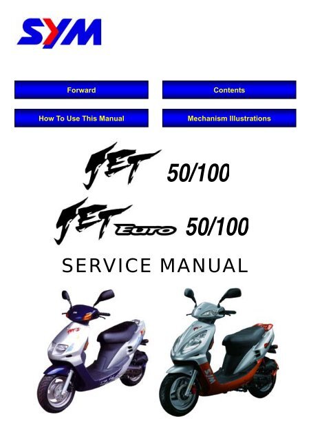
Forward Contents<br />
How To Use This Manual Mechanism Illustrations<br />
50/100<br />
50/100<br />
SERVICE MANUAL
Home page Contents<br />
FORWARD<br />
This service manual contains the technical data of each component inspection<br />
and repair for the SANYANG JET 50/100 and JET <strong>Euro</strong> 50/100 series<br />
motorcycle. The manual is shown with illustrations and focused on “Service<br />
Procedures”, “Operation Key Points”, and “Inspection Adjustment” so that<br />
provides technician with service guidelines.<br />
If the style and construction of the motorcycle, JET 50/100 and JET <strong>Euro</strong><br />
50/100 series, are different from that of the photos, pictures shown in this<br />
manual, the actual vehicle shall prevail. Specifications are subject to change<br />
without notice.<br />
Service Department<br />
Sanyang Industry Co., LTD.
How to Use This Manual<br />
This service manual describes basic information of different system parts and<br />
system inspection & service for Sanyang JET 50/100 and JET <strong>Euro</strong> 50/100<br />
series motorcycles. In addition, please refer to the manual contents in detailed<br />
for the model you serviced in inspection and adjustment.<br />
The first chapter covers general information and trouble diagnosis.<br />
The second chapter covers service maintenance information.<br />
Th third to the tenth nine chapters covers engine and driving systems.<br />
The tenth to the fourteenth is contained the parts set of assembly body.<br />
The fifteenth chapter is electrical equipment.<br />
The sixteenth chapter is wiring diagram<br />
Please see index of content for quick<br />
having the special parts and system<br />
information.<br />
Home page Contents<br />
All information, illustration, directions and specifications included in this manual<br />
are current as at the time of publication. Sanyang reserves the rights to make<br />
changes at any time without prior notice and without incurring any obligation<br />
whatever. Without written consent by SANYANG can not copy any part of this<br />
manual.<br />
There are 4 buttons, “Forward,” “How to use this manual,” “Mechanism<br />
Illustrations,” and “Contents” on the CD-R version, and can be access to<br />
these items by click the mouse.<br />
If user wants to look for the content of each chapter, selecting the words of<br />
each chapter on the main contents can reach to each chapter. There are<br />
two buttons, Back to homepage and Main contents, onto the top line of first<br />
page of the each chapter. Thus, if the user needs to check other chapters, he<br />
can click the top buttons to back the homepage or main contents. The<br />
content of each chapter can be selected too. Therefore, when needs to<br />
checking the content inside of the chapter, click the content words of the<br />
chapter so that can back to the initial section of the content. In addition,<br />
there is a “This chapter contents” button at the top line of each page so that<br />
clicking the button can back to the contents of this chapter.
CONTENTS<br />
Page Content Index<br />
1-1 ~ 1-18 GENERAL INFORMATION<br />
2-1 ~ 2-14 SERVICE MAINTENANCE INFORMATION<br />
3-1 ~ 3-6 LUBRICATION SYSTEM 3<br />
4-1 ~ 4-4 ENGINE REMOVAL 4<br />
5-1 ~ 5-8 CYLINDER HEAD/CYLINDER/PISTON 5<br />
6-1 ~ 6-4 ALTERNATOR 6<br />
7-1 ~ 7-14 “V” TYPE BELT DRIVING SYSTEM/KICK-STARTER 7<br />
8-1 ~ 8-6 FINAL DRIVING MECHANISM 8<br />
9-1 ~ 9-6 CRANKCASE/CRANKSHAFT 9<br />
10-1 ~ 10-10 FUEL SYSTEM<br />
11-1 ~ 11-12 BRAKE SYSTEM<br />
12-1 ~ 12-12 BODY COVER<br />
Home page<br />
13-1 ~ 13-10 STEERING/FRONT WHEEL/SUSPENSION<br />
14-1 ~ 14-4 REAR WHEEL/SUSPENSION<br />
15-1 ~ 15-22 ELECTRICAL EQUIPMENT<br />
1<br />
2<br />
10<br />
11<br />
12<br />
13<br />
14<br />
15<br />
16-1 ~ 16-4 ELECTRICAL DIAGRAM 16
MODEL ILLUSTRATION<br />
JET 50 / 100 Series<br />
Front turn signal<br />
Head light<br />
Front brake lever Rear brake lever<br />
Home page Contents<br />
Frame number<br />
Light / Starter switch<br />
Fuel tank cap<br />
Helmet hook<br />
Rear turn signal<br />
Seat lock<br />
Rear turn signal<br />
High & Low beam /<br />
Turn signal / Horn switch<br />
Battery / Fuses / C.D.I. /<br />
Eng. Oil tank cap<br />
Tail light<br />
Storage box<br />
Air cleaner<br />
Ignition switch<br />
Engine number<br />
Muffler
JET <strong>Euro</strong> Series<br />
Front turn signal<br />
Head light<br />
Home page Contents<br />
Front brake lever Rear brake lever<br />
Frame number<br />
MODEL ILLUSTRATION<br />
Light / Starter switch<br />
Fuel tank cap<br />
Helmet hook<br />
Rear turn signal<br />
Seat lock<br />
Rear turn signal<br />
High & Low beam /<br />
Turn signal / Horn switch<br />
Battery / Fuses / C.D.I. /<br />
Eng. Oil tank cap<br />
Tail light<br />
Storage box<br />
Air cleaner<br />
Ignition switch<br />
Engine number<br />
Muffler
1. GENERAL INFORMATION<br />
General Safety<br />
Carbon monoxide<br />
If you must run your engine, ensure the place is<br />
well ventilated. Never run your engine in a<br />
closed area. Run your engine in an open area, if<br />
you have to run your engine in a closed area, be<br />
sure to use an extractor.<br />
Caution<br />
Exhaust contains toxic gas which may cause<br />
one to lose consciousness and even result in<br />
death.<br />
Gasoline<br />
Gasoline is a low ignition point and explosive<br />
material. Work in a well-ventilated place, no<br />
flame or spark should be allowed in the work<br />
place or where gasoline is being stored.<br />
Caution<br />
Gasoline is highly flammable, and may<br />
explode under some conditions, keep it away<br />
from children.<br />
Used engine oil<br />
Caution<br />
Prolonged contact with used engine oil (or<br />
transmission oil) may cause skin cancer<br />
although it might not be verified.<br />
We recommend that you wash your hands<br />
with soap and water right after contacting.<br />
Keep the used oil beyond reach of children.<br />
Hot components<br />
Caution<br />
Components of the engine and exhaust<br />
system can become extremely hot after<br />
engine running. They remain very hot even<br />
after the engine has been stopped for some<br />
time. When performing service work on these<br />
parts, wear insulated gloves and wait until<br />
cooling off.<br />
1-2<br />
This chapter Contents<br />
Battery<br />
Caution<br />
Battery emits explosive gases; flame is<br />
strictly prohibited. Keep the place well<br />
ventilated when charging the battery.<br />
Battery contains sulfuric acid (electrolyte)<br />
which can cause serious burns so be<br />
careful do not be spray on your eyes or<br />
skin. If you get battery acid on your skin,<br />
flush it off immediately with water. If you get<br />
battery acid in your eyes, flush it off<br />
immediately with water and then go to<br />
hospital to see an ophthalmologist.<br />
If you swallow it by mistake, drink a lot of<br />
water or milk, and take some laxative such<br />
as castor oil or vegetable oil and then go to<br />
see a doctor.<br />
Keep electrolyte beyond reach of children.<br />
Brake shoe<br />
Do not use an air hose or a dry brush to clean<br />
components of the brake system, use a vacuum<br />
cleaner or the equivalent to avoid dust flying.<br />
Caution<br />
Inhaling dust may cause disorders and cancer<br />
of the breathing system.<br />
Brake fluid<br />
Caution<br />
Spilling brake fluid on painted, plastic, or<br />
rubber parts may cause damage to the parts.<br />
Place a clean towel on the above-mentioned<br />
parts for protection when servicing the brake<br />
system. Keep the brake fluid beyond reach of<br />
children.
1. GENERAL INFORMATION<br />
The length of bolts and screws for assemblies,<br />
cover plates or boxes is different from one<br />
another, be sure they are correctly installed. In<br />
case of confusion, Insert the bolt into the hole<br />
to compare its length with other bolts, if its<br />
length out side the hole is the same with other<br />
bolts, it is a correct bolt. Bolts for the same<br />
assembly should have the same length.<br />
Tighten assemblies with different dimension<br />
fasteners as follows: Tighten all the fasteners<br />
with fingers, then tighten the big ones with<br />
special tool first diagonally from inside toward<br />
outside, important components should be<br />
tightened 2 to 3 times with appropriate<br />
increments to avoid warp unless otherwise<br />
indicated. Bolts and fasteners should be kept<br />
clean and dry. Do not apply oil to the threads.<br />
When oil seal is installed, fill the groove with<br />
grease, install the oil seal with the name of the<br />
manufacturer facing outside, check the shaft on<br />
which the oil seal is to be installed for<br />
smoothness and for burrs that may damage the<br />
oil seal.<br />
Remove residues of the old gasket or sealant<br />
before reinstallation, grind with a grindstone if<br />
the contact surface has any damage.<br />
1-4<br />
Manufacturer's name<br />
This chapter Contents<br />
The ends of rubber hoses (for fuel, vacuum, or<br />
coolant) should be pushed as far as they can<br />
go to their connections so that there is enough<br />
room below the enlarged ends for tightening<br />
the clamps.<br />
Rubber and plastic boots should be properly<br />
reinstalled to the original correct positions as<br />
designed.<br />
Boots<br />
The tool should be pressed against two (inner<br />
and outer) bearing races when removing a ball<br />
bearing. Damage may result if the tool is<br />
pressed against only one race (either inner<br />
race or outer race). In this case, the bearing<br />
should be replaced. To avoid damaging the<br />
bearing, use equal force on both races.<br />
Both of these examples can result in bearing damage.<br />
Lubricate the rotation face as assembling.<br />
Check if positions and operation for installed<br />
parts is in correct and properly.
Torque values<br />
1. GENERAL INFORMATION<br />
Standard Torque Values for Reference<br />
Type Torque value Type Torque value<br />
5 mm Bolt, nut 0.45 - 0.6 kg-m 5 mm Bolt 0.35 - 0.5 kg-m<br />
6 mm Bolt, nut 0.8 - 1.2 kg-m 6 mm Bolt, SH nut 0.7 - 1.1 kg-m<br />
8 mm Bolt, nut 1.8 - 2.5 kg-m 6 mm Flange bolt, nut 1.0 - 1.4 kg-m<br />
10 mm Bolt, nut 3.0 - 4.0 kg-m 8 mm Flange bolt, nut 2.4 - 3.0 kg-m<br />
12 mm Bolt, nut 5.0 - 6.0 kg-m 10 mm Flange bolt, nut 3.5 - 4.5 kg-m<br />
The torque values listed in below table are for more important tighten torque values. Please see<br />
above standard values for not listed in the table.<br />
Engine<br />
Cylinder head bolt<br />
Item Q’ty<br />
This chapter Contents<br />
Thread Dia.<br />
(mm)<br />
Torque Value<br />
(Kg-m)<br />
4 6 1.0<br />
Spark plug 1 14 1.4<br />
Flywheel nut 1 10 3.8<br />
Sliding driving disc nut 1 10 3.8<br />
Sliding driving disc nut 1 28 5.5<br />
Clutch outer cover nut 1 10 3.8<br />
Drain bolts 1 8 1.3<br />
Crankcase bolts 6 6 1.0<br />
Remarks<br />
When engine<br />
cooled<br />
1-7
1. GENERAL INFORMATION<br />
Frame<br />
Bolt for engine suspension<br />
1-8<br />
Item Q’ty<br />
Bolt for engine suspension bracket<br />
Upper bolt for rear shock absorber<br />
Lower bolt for rear shock absorber<br />
Mounting screws for exhaust pipe<br />
connection<br />
Nut for exhaust<br />
Brake hose bolts<br />
Brake caliper mounting bolts<br />
Brake cushion guide bolts<br />
Brake cushion guide bolts cap<br />
Brake drain valve<br />
Rear brake arm bolts<br />
Tightening nut for steering rod<br />
Front shaft nut<br />
Mounting bolt for handle<br />
Mounting nut for front hub<br />
Mounting bolt for front brake disc<br />
Rear shaft nut<br />
Nut for rear hub<br />
This chapter Contents<br />
Thread Dia.<br />
(mm)<br />
Torque Value<br />
(Kgf-m)<br />
1 10 5.0<br />
1 12 6.0<br />
1 10 4.0<br />
1 8 2.7<br />
2 6 1.2<br />
2 8 3.3<br />
2 10 3.5<br />
2 8 3.1<br />
2 6 1.8<br />
2 6 1.0<br />
1 6 0.6<br />
1 5 0.55<br />
1 25.4 7.0<br />
1 12 6.0<br />
1 10 5.0<br />
4 8 2.5<br />
3 8 4.5<br />
1 14 11.0<br />
4 8 2.5<br />
Remarks
1. GENERAL INFORMATION<br />
1-10<br />
Starter switch<br />
Front brake<br />
lamp switch<br />
Headlight switch<br />
Headlight<br />
Throttle cable<br />
Speedometer<br />
This chapter Contents<br />
Winker switch<br />
Throttle cable<br />
Main switch<br />
Regulator<br />
Horn<br />
Speedometer cable<br />
High/low beam switch<br />
Horn switch<br />
Rear brake lamp switch<br />
Front brake cable<br />
Speedometer cable<br />
Rear brake cable<br />
Winker relay<br />
Resistor<br />
Front brake hose
Front brake hose<br />
Throttle cable<br />
Speedometer cable<br />
This chapter Contents<br />
Winker relay<br />
Front brake hose<br />
Rear brake cable<br />
Fuel unit<br />
Throttle cable<br />
Rear brake cable<br />
Rear brake cable<br />
Speedometer cable<br />
1. GENERAL INFORMATION<br />
Fuel filter<br />
Throttle cable<br />
Fuel unit cord<br />
Front brake hose Fuel pump<br />
1-11
1. GENERAL INFORMATION<br />
1-12<br />
Fuel pump<br />
Fuel filter<br />
Purge control valve<br />
Oil control cable<br />
Fuel hose<br />
Vacuum hose<br />
This chapter Contents<br />
Fuse<br />
Oil hose<br />
Battery<br />
Rear brake cable<br />
Oil lever switch<br />
C.D.I. UNIT<br />
Carburetor
Troubleshooting<br />
A. Engine hard to start or can not be started<br />
1. GENERAL INFORMATION<br />
Check and adjustment Fault condition Probable causes<br />
Loosen carburetor drain bolt<br />
to check if there is gasoline<br />
inside the carburetor<br />
Fuel supplied tom<br />
carburetor sufficient<br />
Remove spark plug, install<br />
it into spark plug cap, and<br />
perform a spark test<br />
against engine ground.<br />
Check if sparks<br />
Perform cylinder<br />
compression pressure test.<br />
No fuel is supplied to<br />
carburetor<br />
Week sparks or no spark<br />
at all<br />
cylinder compression pressure normal Low compression<br />
pressure or no pressure<br />
Re-start by following the<br />
starting procedures<br />
Remove the spark plug<br />
again and check it.<br />
No ignition<br />
Remove carburetor after 30<br />
minutes and connect a hose<br />
onto fuel supplement circuit.<br />
Then blow the hose with air<br />
This chapter Contents<br />
There are some signs of<br />
ignition, but engine can<br />
not be started<br />
Dry spark plug Wet spark plug<br />
Blowing in normal Blowing clogged<br />
1. No fuel in fuel tank<br />
2. Check if the pipes, fuel tank to<br />
carburetor and intake vacuum, are<br />
clogged.<br />
3. Float valve clogged<br />
4. Lines in fuel tank evaporation system<br />
clogged<br />
5. Malfunction of fuel pump<br />
6. Loosen or damaged fuel pump vacuum<br />
hose<br />
7. Fuel filter clogged<br />
1. Malfunction of spark plug<br />
2. Spark plug foul<br />
3. Malfunction of CDI set<br />
4. Malfunction of AC generator<br />
5. Ignition coil is in open or short circuit<br />
6. Ignition coil leads open or short circuit<br />
7. Malfunction of main switch<br />
1. Piston ring seized<br />
2. Malfunction of cylinder valves<br />
3. Worn cylinder and piston ring<br />
4. Cylinder gasket leak<br />
5. Sand hole in compression parts<br />
6. Crankcase leakage for pre-compression<br />
1. Malfunction of throttle valve operation<br />
2. Air sucked into intake manifold<br />
3. Incorrect ignition timing<br />
1. Fuel level in carburetor too high<br />
2. Malfunction of throttle valve operation<br />
3. Throttle valve opening too wide<br />
1. Malfunction of auto-starter<br />
1-13
1. GENERAL INFORMATION<br />
B. Engine run sluggish (Speed does not pick up, lack of power)<br />
1-14<br />
Check and adjustment Fault condition Probable causes<br />
Try gradual acceleration<br />
and check engine speed<br />
Engine speed can be<br />
increased.<br />
Check ignition timing<br />
(Using ignition lamp)<br />
Check cylinder compression<br />
pressure (using compression<br />
pressure gauge)<br />
Engine speed can not be<br />
increased.<br />
Ignition timing correct Incorrect ignition timing<br />
Compression pressure correct No compression pressure<br />
Check if carburetor is<br />
clogged<br />
Remove spark plug<br />
Check if engine over heat<br />
Normal Clogged<br />
No foul or discoloration Fouled and discoloration<br />
Continually drive in<br />
acceleration or high speed<br />
No knock Knock<br />
This chapter Contents<br />
Normal Engine overheat<br />
1. Air cleaner clogged<br />
2. Poor fuel supply<br />
3. Lines in fuel tank evaporation system<br />
clogged<br />
4. Exhaust pipe clogged<br />
1. Malfunction of CDI<br />
2. Malfunction of AC generator<br />
1. Cylinder & piston ring worn out<br />
2. Cylinder gasket leaked<br />
3. Sand hole in compression parts<br />
4. Valve deterioration<br />
5. Crankcase leakage for<br />
pre-compression<br />
1. Remove dirt<br />
1. Remove dirt<br />
2. Incorrect spark plug heat range<br />
1. Piston and cylinder worn out<br />
2. Lean mixture<br />
3. Poor fuel quality<br />
4. Too much carbon deposited in<br />
combustion chamber<br />
5. Ignition timing too advanced<br />
1. Too much carbon deposited in<br />
combustion chamber<br />
2. Lean mixture<br />
3. Poor fuel quality<br />
4. Lean mixture
C. Engine runs sluggish (especially in low speed and idling)<br />
D. Engine runs sluggish (High speed)<br />
1. GENERAL INFORMATION<br />
Check and adjustment Fault condition Probable causes<br />
Check ignition timing<br />
(using ignition lamp)<br />
Adjust the air screw of<br />
carburetor<br />
Air sucked through<br />
carburetor gasket<br />
Remove spark plug, install<br />
spark plug into spark plug<br />
cap and perform spark test<br />
against engine ground<br />
Check for fuel supplying<br />
system in automatic fuel cup<br />
Check if carburetor clogged<br />
Normal Abnormal<br />
Good Poor<br />
No air sucked Air sucked<br />
Good spark Poor<br />
Good Poor<br />
1. Incorrect ignition timing (malfunction<br />
of CDI or AC generator)<br />
1. Rich mixture (loosen the screw)<br />
2. Lean mixture (tighten the screw)<br />
1. Poor heat insulation gasket<br />
2. Carburetor lock loose<br />
3. Poor intake gasket<br />
4. Poor carburetor O-ring<br />
CHECK AND ADJUSTMENT FAULT CONDITION PROBABLE CAUSES<br />
Check ignition timing<br />
This chapter Contents<br />
Normal Abnormal<br />
1. Spark plug fouled<br />
2. Malfunction of CDI<br />
3. Malfunction of AC generator<br />
4. Malfunction of ignition coil<br />
5. Open or short circuit in spark plug<br />
leads<br />
6. Malfunction of main switch<br />
1. Malfunction of CDI<br />
Normal Clogged 1. Cleaning<br />
2. Malfunction of AC generator<br />
1. Insufficient fuel in fuel tank<br />
2. Fuel filter clogged<br />
3. Restricted fuel tank vent<br />
1-15
1. GENERAL INFORMATION<br />
E. CLUTCH, DRIVING AND DRIVING PULLEY<br />
1-16<br />
FAULT CONDITION PROBABLE CAUSES<br />
Engine can be started but<br />
motorcycle can not be driving<br />
Engine running and misfire as<br />
motorcycle initial forward moving<br />
or jumping sudden (rear wheel<br />
rotating as engine in running)<br />
Poor initial driving (Poor climbing<br />
performance)<br />
This chapter Contents<br />
1. Driving belt worn out or deformation<br />
2. Driving disk damaged<br />
3. Driving pulley spring broken<br />
4. Clutch ling broken<br />
5. Driving slide-shaft gear groove broken<br />
6. Transmission gear damage<br />
7. Transmission gear worn out or burned<br />
1. Clutch ling spring broken<br />
2. Clutch outer cover stuck with clutch balance weights<br />
3. Connection parts in clutch and shaft worn out or<br />
burned<br />
1. Driving belt worn out or deformation<br />
2. Balance weight roller worn out<br />
3. Driving sliding gear shaft worn out<br />
4. Driving disk spring deformation<br />
5. Driving sliding gear shaft worn out<br />
6. Greased in driving belt and sliding gear.
Lubrication Points<br />
Steering shaft bearing<br />
Speedometer gear/ front<br />
wheel bearing<br />
Throttle cable/<br />
Front & rear brake lever pivot<br />
This chapter Contents<br />
Side stand shaft<br />
1. GENERAL INFORMATION<br />
Engine suspension bushing<br />
Main stand shaft<br />
Seat lock<br />
Rear wheel bearing<br />
1-17
1. GENERAL INFORMATION<br />
Note:<br />
1-18<br />
This chapter Contents
2. SERVICE MAINTENANCE INFORMATION<br />
Fuel Filter<br />
Remove the luggage box.<br />
Remove the fuel line from the fuel filter.<br />
Replace the fuel filter with new one.<br />
Install the fuel filter. The arrow indicates the fuel<br />
flowing direction.<br />
Check the fuel line for leaking.<br />
Engine Oil Line<br />
Remove the body cover.<br />
Check the engine oil line and replace damaged<br />
parts.<br />
Remove the filling pipe from the oil pump, and<br />
drain oil into a cleaning container.<br />
Loosen the clamp under the engine oil tank, and<br />
then remove the oil pipe.<br />
Bleed the air inside the oil pump and oil pipe if<br />
air found.<br />
Install the body cover.<br />
2-4<br />
This chapter Contents<br />
Oil pump<br />
Fuel filter<br />
Oil filling pipe<br />
Engine oil pipe
Oil Pump Control Cable<br />
Caution<br />
To adjust the oil pump control cable after<br />
adjusted the throttle grip play.<br />
Remove the body cover.<br />
Wide open the throttle valve, and check if the<br />
calibration point aligns on the oil pump lever with<br />
the mark of pump body.<br />
Loosen the adjustment nut of the oil pump<br />
control cable.<br />
Turn the adjustment nut and align with the point,<br />
then tighten the nut.<br />
This chapter Contents<br />
2. SERVICE MAINTENANCE INFORMATION<br />
Mounting nut<br />
Adjustment nut<br />
2-5
Remove the pin bolt cap.<br />
Loosen the bolt.<br />
Remove the front wheel shaft bolt.<br />
Take out the front wheel.<br />
Remove brake caliper mounting bolt and then<br />
remove the brake caliper.<br />
Caution<br />
Do not operate the brake lever after the<br />
clipper removed to avoid clipping the brake<br />
lining.<br />
Pry out the brake lining with a flat driver if lining<br />
is clipped.<br />
Remove brake lining bolt.<br />
Take out the lining.<br />
Tighten Torque:<br />
Mounting bolt: 2.9-3.5 kgf-m<br />
Pin bolt: 1.5-2.0 kgf-m<br />
Pin bolt cap: 0.8-1.2 kgf-m<br />
The brake LIGHT switch is to light up brake<br />
LIGHT as brake applied. Replace the switch if<br />
the light does not light up in properly.<br />
Caution<br />
The brake light switch is un-adjustable.<br />
This chapter Contents<br />
2. SERVICE MAINTENANCE INFORMATION<br />
Mounting bolt<br />
Pin bolt cap<br />
Brake lining<br />
Pin bolt<br />
Pin bolt<br />
2-9
2. SERVICE MAINTENANCE INFORMATION<br />
Steering System<br />
2-10<br />
Caution<br />
The control cables can not interfere with the<br />
rotation of steering handle.<br />
Lift the front wheel out of ground, and check if<br />
the steering handle turning is smoothly.<br />
If handle turning is uneven and bending, stuck,<br />
or the handle can be operated in vertical<br />
direction, then adjust the handle top bearing by<br />
adjusting the steering nut.<br />
Suspension<br />
Warning<br />
Do not ride the scooter with poor suspension.<br />
Looseness, wear or damage suspension<br />
system will make poor stability and<br />
drive-ability.<br />
Front Shock Absorber<br />
Press down the front shock absorber for several<br />
times to check it operation.<br />
Check if the shock absorber assembly is<br />
damage. Replace it if damage found and can<br />
not be repaired.<br />
Tighten all nuts and bolts.<br />
Rear Shock Absorber<br />
Park the scooter with its main stand.<br />
Shake the rear wheel side to side to check<br />
engine suspension bushing for wear.<br />
Replace the bushing if looseness found.<br />
Check the shock absorber for damage.<br />
Tighten all nuts and bolts.<br />
Nuts, Bolts Tightness<br />
Check if all bolts and nuts on the frame are<br />
tightened to specified torque in accord with the<br />
interval of Periodical Maintenance Schedule.<br />
Check all split pins, snap rings, hose clamps,<br />
and wire holders for security.<br />
This chapter Contents
Transmission Oil<br />
Leak<br />
Check if the transmission is leak.<br />
Check<br />
Caution<br />
Park the scooter on flat ground with its main<br />
stand.<br />
Remove the oil level check bolt, and check if the<br />
oil level is placed on the hole of check bolt.<br />
Replacement<br />
Remove the oil level check bolt.<br />
Remove the oil draining bolt, and then drain oil<br />
out.<br />
Install the oil draining bolt.<br />
Tighten torque: 1.3 kg-m<br />
Caution<br />
Check if oil seal and washer is in good<br />
condition.<br />
Replacement Quantity: 0.09 L (90 cc)<br />
Recommended oil: King Bramax HYPOID<br />
GEAR OIL #140<br />
Spark Plug<br />
Recommended plug: NGK BR8HSA<br />
Remove the luggage box.<br />
Remove the spark plug cap.<br />
Clean any dirt on the spark plug seat.<br />
Remove the spark plug.<br />
Visually inspect the spark plug electrodes<br />
for wear.<br />
The center electrode should have square<br />
edges and side electrode should have a<br />
constant thickness. Replace the spark plug<br />
if there is apparent wear or if the insulator is<br />
cracked and/or chipped. If the spark plug<br />
deposits can be removed by sandpaper, the<br />
spark plug can be reused.<br />
Measure the spark plug gap with feeler<br />
gauge.<br />
Spark plug gap: 0.6-0.7mm<br />
(0.024-0.028in)<br />
Adjust the gap by careful bending the side<br />
electrode.<br />
Install the spark plug by screwing it with<br />
hands after installed the spark plug washer<br />
so that can prevent the plug from out of<br />
thread. Then, tighten the spark plug with a<br />
spark plug wrench.<br />
Install the spark plug cap.<br />
This chapter Contents<br />
2. SERVICE MAINTENANCE INFORMATION<br />
Draining bolt<br />
0.6~0.7mm<br />
Side electrode<br />
Center electrode<br />
Oil level check bolt<br />
Oil level check bolt hole<br />
2-11
2. SERVICE MAINTENANCE INFORMATION<br />
Headlight Adjustment<br />
Loosen headlight mounting bolt.<br />
Move the headlight for adjustment its light beam.<br />
Tighten the headlight mounting bolt after<br />
adjusted.<br />
Caution<br />
Improper headlight beam adjustment will<br />
make in coming driver dazzled or insufficient<br />
lighting for safety distance.<br />
2-14<br />
This chapter Contents<br />
Headlight mounting bolt<br />
Headlight mounting bolt
Lubrication System Diagram············ 3-1<br />
Precautions In Operation·················· 3-2<br />
Lubricant············································ 3-2<br />
Trouble Shooting······························· 3-2<br />
Lubrication System Diagram<br />
Oil output tube<br />
Oil pump<br />
Oil tank<br />
Home page Contents<br />
Oil tube<br />
3. LUBRICATION SYSTEM<br />
Oil Pump Removal ···························· 3-3<br />
Oil Pump Installation ························ 3-3<br />
Oil Pump/Oil Tube Air Bleeding······· 3-4<br />
Oil Tank ············································· 3-5<br />
Oil lever switch<br />
3-1<br />
3
3. LUBRICATION SYSTEM<br />
Precautions In Operation<br />
Be careful not let dirt enter into engine or oil hoses when removing or installing the oil pump.<br />
If air is found in the oil tube (from oil tank to oil pump) or oil tube is removed, the oil pump should<br />
be conducted air-bleeding operation.<br />
It should bleed the oil output tube (from oil pump to carburetor) as hose removed.<br />
The adjustment of oil pump control cable.<br />
Lubricant<br />
Appointed to apply SAE 20 JASO FC class oil. Otherwise, warranty shall not cover the damage.<br />
Recommended Oil: MAX-2 oil.<br />
Oil tank capacity: 1.2 lit.<br />
Trouble Shooting<br />
Too much smoke, carbon in spark plug.<br />
1. Improperly oil pump adjustment (too much oil).<br />
2. Poor quality oil.<br />
3. Applying with poor quality oil.<br />
Over heat<br />
1. Improperly oil pump adjustment (insufficient oil).<br />
2. Poor quality oil.<br />
3. Applying with poor quality oil.<br />
Piston seized<br />
1. No oil in oil tank or clogged hose.<br />
2. Improperly oil pump adjustment (insufficient oil).<br />
3. Air in oil hose.<br />
4. Malfunction of oil pump.<br />
Oil did not flow out the oil tank<br />
1. Clogged breath hole on the oil tank cover.<br />
3-2<br />
This chapter Contents
Oil Pump Removal<br />
Caution<br />
Before removing the oil pump, clean the oil<br />
pump and crankcase.<br />
Remove the luggage box and seat.<br />
Loosen the mounting nut of the oil pump control<br />
cable, and remove the control cable.<br />
Remove the oil tube, and clip its end side to<br />
prevent oil from flowing out.<br />
Remove the oil output tube form intake manifold.<br />
Remove the oil pump mounting bolt, and then<br />
take out the oil pump.<br />
Inspection<br />
Inspect the following items on the removed oil<br />
pump.<br />
Check if O-ring is damaged or softening.<br />
Check if crankcase interface is damaged.<br />
Check if pump body is damaged.<br />
Check if pump gear is damaged.<br />
Check for oil leaking.<br />
Caution<br />
The oil pump can not be disassembled.<br />
Oil Pump Installation<br />
Install the oil pump onto the crankcase.<br />
Caution<br />
Apply with some grease onto oil pump<br />
O-ring.<br />
The connection between both oil pump and<br />
crankcase has to be installed in position<br />
security.<br />
Tighten the oil pump mounting bolt security.<br />
Install the oil tube.<br />
Installation in the reverse order of removal.<br />
Caution<br />
Inspection and adjustment following items as<br />
installed.<br />
The adjustment operation of control cable.<br />
Air bleeding operation of oil pump.<br />
Air bleeding operation of oil tube.<br />
Check each section for leaking.<br />
This chapter Contents<br />
Oil output tube<br />
Control cable<br />
3. LUBRICATION SYSTEM<br />
Mounting nut<br />
Oil tube<br />
Adjustment nut<br />
Oil output tube<br />
3-3
3. LUBRICATION SYSTEM<br />
Oil Pump/Oil Tube Air Bleeding<br />
3-4<br />
Caution<br />
The oil tube system has to be conducted air<br />
bleeding operation because air will clog or<br />
restraint oil flowing so that cause serious<br />
engine damage.<br />
Caution<br />
After disconnect the oil tube, air enters oil<br />
tube due to oil leak out without added oil.<br />
There is why the oil tube and oil pump have to<br />
conduct air bleeding operation.<br />
Oil Tube/Oil Pump<br />
It has to add some oil into the oil tank.<br />
Place a piece of dry cloth around the oil<br />
pump.<br />
Disconnect the oil tube.<br />
Fill out oil to oil pump connection section by<br />
means of the oil pot so that the oil pump body<br />
is full with oil.<br />
Fill out oil to oil tube connection section so<br />
that the oil tube is full with oil. Then, install<br />
the tube onto oil pump.<br />
Make sure whether air is in the oil tube or not<br />
after installation.<br />
Caution<br />
After bleeding the oil tube and oil pump, the<br />
oil tube has to be conducted air bleeding<br />
operation too.<br />
Oil Tube Air Bleeding<br />
Remove the oil output tube and plug its input<br />
connector. Bend the oil tube into “U “shape,<br />
and fill out new oil into the output tube.<br />
Connect the oil output tube to the oil pump<br />
connection part.<br />
Start engine, and run it in idling as the oil control<br />
lever in wide open position. Make sure oil flows<br />
out from the oil output tube.<br />
Caution<br />
Motorcycle’s exhaust gas includes with CO<br />
which causes human to coma or death so<br />
perform this operation in well-ventilation<br />
place.<br />
Run the engine in extreme low speed to<br />
avoid to damaging the engine caused from<br />
clogged oil tube.<br />
This chapter Contents<br />
Oil output tube<br />
Oil output tube<br />
Oil tube<br />
Oil tube<br />
Control cable<br />
Recommended oil
Oil Tank<br />
Removal/Installation<br />
Remove the luggage box and seat.<br />
Remove the battery and battery box.<br />
Remove the R/L. side cover, rear center cover,<br />
rear carrier and body cover.<br />
Remove the rear fender.<br />
Remove the oil input tube from oil pump, and<br />
then drain oil to a clean container.<br />
Remove the oil switch wire of the oil indicator.<br />
Remove the mounting bolt on the oil tank upper<br />
side, and then remove the oil tank.<br />
Installation in the reverse order of removal.<br />
Air bleeding the oil tubes after installation.<br />
This chapter Contents<br />
Mounting bolt<br />
Blot ×1<br />
Blot ×2<br />
3. LUBRICATION SYSTEM<br />
Screw ×2<br />
3-5
3. LUBRICATION SYSTEM<br />
NOTES:<br />
3-6<br />
This chapter Contents
Maintenance Information ················ 4-1<br />
Engine removal ································ 4-2<br />
Home page Contents<br />
Maintenance Information<br />
There are parts that require removal of engine for maintenance.<br />
Crankcase<br />
Crankshaft<br />
Related bolts tightening torque for removal of engine:<br />
Engine hanger bolt 5.0kgf-m<br />
Engine bracket bolt 6.0kgf-m<br />
Rear shock absorber upper mounting bolts 4.0kgf-m<br />
Rear shock absorber lower mounting bolts 2.7kgf-m<br />
Exhaust pipe connection nut 1.2kgf-m<br />
Muffle mounting bolt 3.3kgf-m<br />
4. ENGINE REMOVAL<br />
Engine installation····························4-4<br />
4-1<br />
4
4. ENGINE REMOVAL<br />
Engine removal<br />
Remove body cover.<br />
Remove the spark plug cap from the spark plug<br />
section.<br />
Remove the fuel output and the vacuum tubes<br />
from fuel pump.<br />
Remove the oil control cable from oil pump.<br />
Remove the oil tube from oil pump and then clip<br />
the tube.<br />
Remove the wire connectors of auto by starter<br />
and ACG.<br />
Remove the upper part of the carburetor from its<br />
upper side.<br />
Remove the vapor emission vacuum tube from<br />
carburetor intake manifold.<br />
4-2<br />
This chapter Contents<br />
Vacuum tube<br />
Fuel output tube<br />
Fuel pump<br />
Spark plug<br />
Oil tube<br />
Oil control cable<br />
Wire connector
Remove rear brake cable from engine rear-lower<br />
side.<br />
Remove air cleaner mounting bolts. (2 bolts)<br />
Support the engine and then remove shock<br />
absorber lower mounting bolt.<br />
Remove two exhaust pipe connection nuts.<br />
Remove two bolts beside fan cover and exhaust<br />
pipe.<br />
This chapter Contents<br />
4. ENGINE REMOVAL<br />
Mounting bolt<br />
Exhaust pipe Bolt<br />
Brake cable<br />
Shock absorber lower<br />
mounting bolt<br />
Connection nut<br />
4-3
4. ENGINE REMOVAL<br />
Remove engine mounting nut and bolt.<br />
Engine installation<br />
Install in the reverse order of removal<br />
procedures.<br />
Tighten the engine mounting and rear shock<br />
absorber upper/lower bolts.<br />
Torque value:<br />
Engine hanger bolt:<br />
Rear shock absorber upper<br />
mounting bolts:<br />
Rear shock absorber lower<br />
mounting bolts:<br />
Exhaust pipe connection nut:<br />
Muffle mounting bolt:<br />
4-4<br />
5.0kgf-m<br />
4.0kgf-m<br />
2.7kgf-m<br />
1.2kgf-m<br />
3.3kgf-m<br />
Perform the following inspection and adjustment<br />
after installation.<br />
Check if control cable is correct.<br />
Check if throttle valve cable is correct.<br />
Check if oil pump control cable is correct.<br />
Oil input and output of the oil pump.<br />
Adjust rear brake.<br />
This chapter Contents<br />
Engine mounting bolt
Maintenance Information·················· 5-2<br />
Troubleshooting································ 5-2<br />
Home page Contents<br />
5. CYLINDER HEAD/CYLINDER/PISTON<br />
Cylinder Head ·····································5-3<br />
Cylinder/Piston···································5-5<br />
5-1<br />
5
5. CYLINDER HEAD/CYLINDER/PISTON<br />
Maintenance Information<br />
Precautions In Operation<br />
The inspection and maintenance of the cylinder head, cylinder and piston can be carried as<br />
engine mounted on the body.<br />
It should clean the engine to prevent dirt from entering into cylinder and crankcase before<br />
removal.<br />
Remove all washes from the interfaces of cylinder head, cylinder and crankcase.<br />
Be careful do not damage cylinder head, cylinder and piston when removing.<br />
Inspect the removed & cleaned parts thoroughly, and apply with oil onto the rotation surfaces<br />
before installation.<br />
Specification<br />
Cylinder<br />
head<br />
5-2<br />
Item Standard value<br />
(mm)<br />
JET 50 series JET 100 series<br />
Limit (mm)<br />
Standard value<br />
(mm)<br />
Limit (mm)<br />
Deformation - 0.100 - 0.100<br />
Piston OD 39.030~39.045 38.935 51.030~39.045 50.935<br />
Clearance between<br />
cylinder and piston<br />
0.040~0.050 0.100 0.040~0.050 0.100<br />
Piston pin hole 12.002~12.008 12.030 14.002~14.008 14.030<br />
Piston pin OD<br />
Piston<br />
Clearance between<br />
piston and piston pin<br />
11.994~12.000<br />
0.002~0.014<br />
11.970<br />
0.030<br />
13.994~14.000<br />
0.002~0.014<br />
13.970<br />
0.030<br />
Piston ring end gap 0.100~0.250 0.400 0.100~0.250 0.400<br />
ID of connecting rod<br />
small end<br />
17.05~17.015 17.025 17.05~17.015 17.025<br />
ID<br />
Cylinder<br />
Deformation<br />
39.000~39.015<br />
-<br />
39.050<br />
0.100<br />
51.000~51.015<br />
-<br />
51.050<br />
0.100<br />
ID: inner diameter<br />
OD: outer diameter<br />
Tighten torque value<br />
Cylinder head 1.0 kgf-m Exhaust pipe connection nut 1.2 kgf-m<br />
Spark plug 1.4 kgf-m Exhaust muffler mounting bolt 3.3 kgf-m<br />
Troubleshooting<br />
Compression Pressure Too Low/Difficult<br />
To Start/Rough Idling<br />
1. Cylinder head gasket leaking<br />
2. Spark plug not tighten enough<br />
3. Worn, seized or crack piston ring<br />
4. Damaged, worn cylinder or piston<br />
5. Poor reed<br />
Compression Pressure Too<br />
High/Overheat/Knock<br />
1. Too much carbon deposit built up in<br />
combustion chamber<br />
This chapter Contents<br />
Piston Noise<br />
1. cylinder and piston worn out<br />
2. piston pin or piston pin hole worn out<br />
3. connecting rod small end bearing worn out<br />
Piston Ring Noise<br />
1. Worn, seized or crack piston ring<br />
2. Cylinder worn out or damaged
Cylinder Head<br />
Cylinder Removal<br />
Removal body covers.<br />
Remove spark plug cap.<br />
Remove fan cover.<br />
Remove engine shield.<br />
Remove two connection nuts of the exhaust<br />
pipe.<br />
Remove exhaust muffle mounting bolt, and then<br />
remove the exhaust pipe.<br />
Cylinder Head Removal<br />
Remove the 4 cylinder head bolts and then<br />
remove the cylinder head.<br />
Caution<br />
Loosen the cylinder head bolts with diagonal<br />
direction to avoid to damaging it.<br />
Cleaning Carbon In Combustion<br />
Chamber<br />
Clean carbon deposit in which built up in<br />
combustion chamber with shown chisel.<br />
Caution<br />
Do not scratch to the interfaces of combustion<br />
chamber and cylinder.<br />
This chapter Contents<br />
5. CYLINDER HEAD/CYLINDER/PISTON<br />
Tightening bolt<br />
Muffle<br />
Tightening bolts<br />
Chisel<br />
Bolt x 2<br />
Tightening bolt<br />
Engine shield<br />
Tightening bolt x 2<br />
5-3
5. CYLINDER HEAD/CYLINDER/PISTON<br />
Cylinder Head Inspection<br />
Use a straight edge and a feeler gauge to<br />
measure the cylinder head for warp.<br />
Service limit: 0.10 mm<br />
Cylinder Head Installation<br />
Replace the cylinder head gasket with new one,<br />
and place the cylinder head onto cylinder.<br />
Tighten the 4 bolts with diagonal direction and<br />
by 2-3 sequences.<br />
Tighten torque: 1.0 kgf-m<br />
Install spark plug<br />
Tighten torque: 1.4 kgf-m<br />
Replace the exhaust pipe washer with new one<br />
and then install exhaust pipe.<br />
Tighten exhaust pipe connection nut.<br />
Tighten torque: 1.2 kgf-m<br />
Tighten exhaust pipe mounting bolt.<br />
Tighten torque: 3.3 kgf-m<br />
Install the removed parts in the reverse order of<br />
removal procedures.<br />
Inspect following item after installation.<br />
Compression pressure test.<br />
Check for engine noise.<br />
5-4<br />
This chapter Contents<br />
Tightening bolts<br />
Muffle<br />
Bolt x 2<br />
Tightening bolt x 2
Cylinder/Piston<br />
Cylinder Removal<br />
Be careful to pull the cylinder up and prevent<br />
piston from damage.<br />
Caution<br />
Do not have pry out operation between<br />
cylinder and crankcase. Or let radiation fan<br />
be knocked seriously.<br />
Piston Removal<br />
Place a clean rag onto crankshaft to cover the<br />
piston.<br />
Remove piston pin clip (one piece) and then<br />
push piston pin out the piston.<br />
Caution<br />
Do not damage or scratch the piston.<br />
Do not apply with lateral force to<br />
connecting rod.<br />
Do not let piston pin snap ring falling into<br />
crankcase.<br />
Piston Ring Removal<br />
Caution<br />
Pry out the opening end of each piston ring<br />
and then remove the ring from piston.<br />
Check if cylinder and piston are worn or<br />
damaged, and then clean carbon deposit on<br />
exhaust opening area as the diagram shown.<br />
Caution<br />
Do not scratch both the cylinder and the<br />
piston.<br />
This chapter Contents<br />
5. CYLINDER HEAD/CYLINDER/PISTON<br />
Piston pin clip Piston pin<br />
Piston<br />
5-5
5. CYLINDER HEAD/CYLINDER/PISTON<br />
Use a straight edge and a feeler gauge to<br />
measure the cylinder head for warp.<br />
Service limit: 0.10 mm<br />
In “X” and “Y” direction, measure the cylinder for<br />
worn out as the three levels shown in the figure.<br />
With the max. value to decide cylinder wear out<br />
condition.<br />
Service limit<br />
JET 50 : 39.050mm<br />
JET 100 : 51.050mm<br />
Measure the OD of piston at the 7 mm from the<br />
bottom of the piston.<br />
Service limit<br />
JET 50 : 38.935 mm<br />
JET 100 : 50.935 mm<br />
Calculate the clearance between piston and<br />
cylinder.<br />
Service limit: 0.100 mm<br />
Measure the ID of piston pin hole.<br />
Service limit<br />
JET 50 : 12.030mm<br />
JET 100 : 14.030 mm<br />
Measure the OD of piston pin.<br />
Service limit<br />
JET 50 : 11.970 mm<br />
JET 100 : 13.970 mm<br />
5-6<br />
This chapter Contents<br />
The ID of piston pin hole<br />
7mm<br />
The OD of piston pin
Piston Ring Inspection<br />
Measure the end gap of each piston ring.<br />
Service limit: 0.40 mm<br />
Caution<br />
With the piston, push each piston ring into<br />
cylinder correctly.<br />
Connecting Rod Inspection<br />
Install bearing and piston pin onto connecting<br />
rod small end, and then check its clearance.<br />
Measure the ID of connecting rod small end.<br />
Service limit: 17.025mm<br />
Piston/Cylinder Installation<br />
Install the expanding ring into the groove of 2 nd<br />
ring.<br />
Align the ring end with the lock pin in the ring<br />
groove.<br />
Install the top ring and the 2 nd ring onto the ring<br />
groove respective.<br />
Caution<br />
The top ring and the 2 nd ring can not be<br />
changeable each other.<br />
Push the rings into ring groove and then check<br />
rings’ mating condition.<br />
If ring could not be push in the ring groove, it<br />
means that ring groove is dirty or wrong ring<br />
groove installation.<br />
Caution<br />
All rings should be installed with the marks<br />
facing up.<br />
All ring should be replaced at same time,<br />
and it can not be replaced one ring only.<br />
It should use same brand name piston ring<br />
in an engine and can not mix with other<br />
one.<br />
This chapter Contents<br />
5. CYLINDER HEAD/CYLINDER/PISTON<br />
1T: top ring<br />
2T: 2 nd ring<br />
Clearance<br />
Top ring<br />
2 nd ring<br />
Piston ring mark<br />
Expanding ring<br />
5-7
Maintenance Information ················ 6-2<br />
Alternator Removal·························· 6-3<br />
Home page Contents<br />
3.8 kgf-m<br />
6. ALTERNATOR<br />
Alternator Installation······················· 6-4<br />
6-1<br />
6
Alternator Removal<br />
Remove the body cover.<br />
Remove two bolts and then take out cooling fan<br />
cover.<br />
Remove four bolts, and then take out the cooling<br />
fan.<br />
Hold flywheel with universal holder.<br />
Support the flywheel and the remove the 10 mm<br />
nut on the flywheel.<br />
Remove the flywheel with rotor puller.<br />
This chapter Contents<br />
Cooling fan cover<br />
Bolt<br />
6. ALTERNATOR<br />
Rotor puller<br />
Cooling fan<br />
10mm flanged nut<br />
Universal holder<br />
6-3
6. ALTERNATOR<br />
Disconnect alternator wire connector and pulse<br />
generator connector.<br />
Remove the pulse generator and alternator four<br />
(4) bolts, and then take out the alternator<br />
assembly.<br />
Caution<br />
Care to be taken for not damaging the<br />
alternator coil.<br />
Alternator Installation<br />
Install the alternator assembly.<br />
Connect the alternator connector.<br />
Caution<br />
Connect the alternator wire harness properly<br />
and then clip the harness with clipper.<br />
Install the woodruff key onto the crankshaft<br />
groove.<br />
Caution<br />
Clean dirt and metal pieces inside the<br />
flywheel.<br />
Make sure that there is no foreign material<br />
inside the flywheel.<br />
Install the flywheel<br />
Tighten the flywheel 10 mm nut.<br />
Torque value: 3.8 kgf-m<br />
Install the removed parts in reverse order of<br />
removal procedures.<br />
Start engine and check its ignition timing.<br />
6-4<br />
This chapter Contents<br />
Wire harness connector<br />
10mm flanged nut<br />
Universal holder
Maintenance Information ················ 7-2<br />
Trouble Shooting ····························· 7-2<br />
Left Crankcase Cover ······················ 7-3<br />
Reassembly Of Kick Starter············ 7-4<br />
Installation Of The Left Crankcase<br />
Cover················································· 7-4<br />
Home page Contents<br />
7. “V” TYPE BELT DRIVE SYSTEM/KICK-STARTER<br />
Drive Belt···········································7-5<br />
Movable Driven Pulley ·····················7-6<br />
Clutch/Driven Pulley·························7-10<br />
5.5 kgf-m<br />
3.8 kgf-m<br />
3.8 kgf-m<br />
7-1<br />
7
7. “V” TYPE BELT DRIVE SYSTEM/KICK-STARTER<br />
Maintenance Information<br />
Precautions In Operation<br />
The surfaces of drive belt and driven pulley must be free of grease.<br />
Specification<br />
Item Standard value(mm) Limit(mm)<br />
Drive belt width 18.0 16.5<br />
ID of movable drive face 20.035~20.085 20.120<br />
OD of movable drive face boss 23.964~23.985 23.918<br />
OD of weight roller 15.92~16.08 15.40<br />
ID of clutch outer 107.0~107.2 107.5<br />
Thickness of clutch weight 4.0~4.1 2.0<br />
Free length of driven pulley spring 87.9 82.5<br />
OD of driven pulley 33.965~33.985 33.940<br />
ID of movable driven face 33.000 34.060<br />
ID: Inner Diameter<br />
OD: Outer diameter<br />
Torque Values:<br />
Movable drive face: 3.8 kgf-m<br />
Driven pulley: 5.5 kgf-m<br />
Clutch outer: 3.8 kgf-m<br />
Trouble Shooting<br />
Engine can be started but motorcycle<br />
can not be moved<br />
1. Worn drive Belt<br />
2. Worn ramp plate<br />
3. Worn or damaged clutch weight<br />
4. Broken driven pulley spring<br />
Shudder or misfire when drive<br />
1. Broken clutch weight<br />
2. Worn clutch weight<br />
7-2<br />
This chapter Contents<br />
Special Service Tools<br />
Clutch spring compressor<br />
Bearing driver<br />
Clutch nut wrench 39x41 mm<br />
Bearing driver accessory 39x41 mm<br />
Universal holder<br />
Driver<br />
Insufficient horsepower or poor high<br />
speed performance<br />
1. Worn drive belt<br />
2. Insufficient spring capacity of driven pulley<br />
3. Worn weight roller<br />
4. Driven pulley operation un-smoothly
Left Crankcase Cover<br />
Left crankcase cover removal<br />
Remove left body side cover.<br />
Remove air cleaner.<br />
Remove kick start arm.<br />
Remove left crankcase cover.<br />
Disassembly of Kick Starter<br />
Remove snap clip and thrust washer from left<br />
crankcase cover.<br />
Install kick start arm, rotate the lever slightly and<br />
then remove driven gear and washer.<br />
Remove the kick starter arm, kick starter spindle,<br />
and return spring as well as socket.<br />
Inspection of kick Starter<br />
Check if starter spindle, driven gear for wear or damage.<br />
Starter spindle<br />
Return spring<br />
This chapter Contents<br />
7. “V” TYPE BELT DRIVE SYSTEM/KICK-STARTER<br />
Bush<br />
Left crankcase cover<br />
Kick start arm<br />
Return spring<br />
Starter spindle<br />
Thrust washer<br />
Driven gear<br />
Friction spring<br />
Bolt<br />
Snap ring<br />
Thrust washer<br />
Kick start arm<br />
Driven gear<br />
7-3
7. “V” TYPE BELT DRIVE SYSTEM/KICK-STARTER<br />
Reassembly Of Kick Starter<br />
Install bush, return spring and starter spindle as<br />
diagram shown.<br />
Install thrust washer and snap clip onto starter<br />
spindle.<br />
Install Kick starter lever temporary.<br />
Slightly rotate the lever and then align driven<br />
gear with width-tooth on the starter spindle.<br />
Install the friction spring of drive gear onto<br />
convex part of the cover.<br />
Installation Of The Left Crankcase<br />
Cover<br />
Install the dowel pin and gasket.<br />
Install the left crankcase cover.<br />
Install kick start arm.<br />
7-4<br />
This chapter Contents<br />
Return spring<br />
Dowel pin<br />
Width-tooth<br />
Convex part<br />
Kick starter spindle<br />
Driven gear<br />
Friction spring
Drive Belt<br />
Removal<br />
Remove left crankcase cover.<br />
Hold clutch outer with universal holder, and<br />
remove nut and clutch outer.<br />
Caution<br />
Using special tools for tightening or<br />
loosening the nut.<br />
Fixed rear wheel or rear brake will damage<br />
reduction gear system.<br />
Push the drive belt into belt groove as diagram<br />
shown so that the belt can be loosened, and<br />
then remove the driven pulley.<br />
Remove driven pulley/clutch. Do not remove<br />
drive belt.<br />
Remove the drive belt from the groove of driven<br />
pulley.<br />
Inspection<br />
Check the drive belt for crack or wear. Replace<br />
it if necessary.<br />
Measure the width of drive belt as diagram<br />
shown.<br />
Service Limit: 16.5 mm<br />
Replace the belt if exceeds the service limit.<br />
Caution<br />
Using the genuine parts for replacement<br />
The surfaces of drive belt or pulley must be<br />
free of grease.<br />
Clean up all grease or dirt before<br />
installation.<br />
Installation<br />
Caution<br />
Pull out driven pulley to avoid it closing.<br />
Install drive belt onto driven pulley.<br />
This chapter Contents<br />
7. “V” TYPE BELT DRIVE SYSTEM/KICK-STARTER<br />
Belt tooth<br />
Clutch/drive belt<br />
Nut<br />
Universal holder<br />
Movable driven<br />
pulley<br />
7-5
7. “V” TYPE BELT DRIVE SYSTEM/KICK-STARTER<br />
Install the driven pulley that has installed the belt<br />
onto drive shaft.<br />
Install the clutch with universal holder, and then<br />
tighten nut to specified torque value.<br />
Torque value: 3.8 kgf-m<br />
Movable Drive Face<br />
Removal<br />
Remove left crankcase cover.<br />
Hold generator flywheel with universal holder,<br />
and then remove drive face nut.<br />
Remove drive face.<br />
7-6<br />
This chapter Contents<br />
Drive face<br />
Clutch/driven pulley<br />
Nut<br />
Drive face<br />
Drive belt<br />
Universal holder<br />
Drive shaft<br />
Clutch outer<br />
Universal holder<br />
Flywheel<br />
Nut
Removal<br />
Remove movable drive face set and drive belt<br />
from crankshaft.<br />
Remove ramp plate.<br />
Remove weight rollers from movable face.<br />
Inspection<br />
The weight roller is to press movable driven face<br />
by means of centrifuge force. Thus, if weight<br />
rollers are worn out or damage, the centrifuge<br />
force will be affected.<br />
Check if rollers are wear out or damage.<br />
Replace it if necessary.<br />
Measure each roller’s outer diameter. Replace it<br />
if exceed the service limit.<br />
Service limit: 15.40 mm<br />
This chapter Contents<br />
7. “V” TYPE BELT DRIVE SYSTEM/KICK-STARTER<br />
Drive face boss<br />
Crankshaft<br />
Movable drive face<br />
Weight roller<br />
Movable drive face<br />
Ramp plate<br />
Weight roller<br />
7-7
7. “V” TYPE BELT DRIVE SYSTEM/KICK-STARTER<br />
Check if movable drive face boss is worn or<br />
damage and replace it if necessary.<br />
Measure the outer diameter of drive face boss,<br />
and replace it if it exceed service limit.<br />
Service limit: 19.98 mm<br />
Measure the inner diameter of drive face, and<br />
replace it if it exceed service limit.<br />
Service limit: 20.120 mm<br />
Reassembly / Installation<br />
Install weight rollers.<br />
Install ramp plate.<br />
Apply with grease 4~5g to inside of movable<br />
drive face, and install drive face boss.<br />
7-8<br />
Caution<br />
The drive face has to be free of grease.<br />
Clean it with cleaning solvent.<br />
This chapter Contents<br />
Drive face<br />
Ramp plate<br />
Movable drive face<br />
Drive face boss<br />
Weight roller
Install movable drive face assembly onto<br />
crankshaft.<br />
Drive Face Installation<br />
Press drive belt into pulley groove, and then pull<br />
the belt on to crank shaft.<br />
Install drive face, washer and nut.<br />
Caution<br />
Make sure that two sides of drive face have<br />
to be free of grease. Clean it with cleaning<br />
solvent.<br />
Hold flywheel with universal holder.<br />
Tighten nut to specified torque.<br />
Torque value: 3.5-4.0 kgf-m<br />
Install left crankcase cover.<br />
This chapter Contents<br />
7. “V” TYPE BELT DRIVE SYSTEM/KICK-STARTER<br />
Drive face boss<br />
Crankshaft<br />
Flywheel<br />
Drive face<br />
Press down<br />
Drive belt<br />
Movable drive face<br />
Universal holder<br />
Nut<br />
7-9
7. “V” TYPE BELT DRIVE SYSTEM/KICK-STARTER<br />
Clutch/Driven Pulley<br />
Disassembly<br />
Remove drive belt and clutch/driven pulley.<br />
Install clutch spring compressor onto the pulley<br />
assembly, and operate the compressor to let nut<br />
be installed more easily.<br />
7-10<br />
Caution<br />
Do not press the compressor too much.<br />
Hold the clutch spring compressor onto bench<br />
vise, and then remove mounting nut with clutch<br />
nut wrench.<br />
Release the clutch spring compressor and<br />
remove clutch and spring from driven pulley.<br />
Remove socket from sliding pulley.<br />
Remove guide pin, guide pin roller, and driven<br />
pulley, and then remove O-ring & oil seal seat<br />
from sliding pulley.<br />
Inspection<br />
Clutch outer<br />
Measure the inner diameter of clutch outer<br />
friction face. Replace clutch outer if exceed<br />
service limit.<br />
Service limit: 107.5 mm<br />
This chapter Contents<br />
Sliding pulley<br />
O-ring<br />
Inner<br />
diameter<br />
Oil seal<br />
Clutch nut<br />
wrench<br />
Clutch spring<br />
compressor<br />
Guide pin<br />
or<br />
Clutch outer<br />
Socket<br />
Guide pin roller
Clutch weight<br />
Measure each clutch weight thickness.<br />
Replace it if exceeds service limit.<br />
Service limit: 2.0 mm<br />
Driven pulley spring<br />
Measure the length of driven pulley spring.<br />
Replace it if exceeds service limit.<br />
Service limit: 82.5 mm<br />
Driven pulley<br />
Check following items:<br />
If both surfaces are damage or wear.<br />
If guide pin groove is damage or wear.<br />
Replace damaged or worn components.<br />
Measure the outer diameter of driven pulley and<br />
the inner diameter of sliding pulley. Replace it<br />
if exceeds service limit.<br />
Service limit: Outer diameter 33.94 mm<br />
Inner diameter 34.06 mm<br />
Driven Pulley Bearing Inspection<br />
Check if the inner bearing oil seal is damage.<br />
Replace it if necessary.<br />
Check if needle bearing is damage or too big<br />
clearance. Replace it if necessary.<br />
Rotate the inside of inner bearing with fingers to<br />
check if the bearing rotation is in smooth and<br />
silent. Check if the bearing outer parts are<br />
closed and fixed. Replace it if necessary.<br />
Caution<br />
Some of models are equipped with two ball<br />
bearings.<br />
This chapter Contents<br />
7. “V” TYPE BELT DRIVE SYSTEM/KICK-STARTER<br />
Outer ball bearing<br />
Clutch weight<br />
Free length<br />
Driven pulley<br />
Sliding pulley<br />
Guide pin groove<br />
Needle bearing<br />
7-11
7. “V” TYPE BELT DRIVE SYSTEM/KICK-STARTER<br />
Clutch Block Replacement<br />
Remove clip and washer, and then remove<br />
clutch weight and spring from drive plate.<br />
7-12<br />
Caution<br />
Some of models are equipped with one<br />
mounting plate instead of 3 snap clips.<br />
Check if spring is damage or insufficient<br />
elasticity.<br />
Check if shock absorption rubber is damage or<br />
deformation. Replace it if necessary.<br />
Apply with grease onto lock pins.<br />
Install new clutch weight onto lock pin and then<br />
push to specific location.<br />
Apply with grease onto lock pins. But, the<br />
clutch weight should not be greased. If so,<br />
replace it.<br />
Caution<br />
Grease or lubricant will damage the clutch<br />
weight and affect the weight’s connection<br />
capacity.<br />
Install the spring into groove with pliers.<br />
This chapter Contents<br />
Spring<br />
Clutch weight<br />
Shock absorption<br />
rubber<br />
Shock absorption rubber<br />
Clutch block<br />
Spring<br />
Drive plate<br />
Snap clip
Install snap clip and mounting plate onto lock<br />
pin.<br />
Replacement of Driven Pulley Bearing<br />
Remove inner bearing.<br />
Caution<br />
If the inner bearing equipped with oil seal<br />
on side in the driven pulley, then remove<br />
the oil seal firstly.<br />
If the pulley equipped with ball bearing, it<br />
has to remove snap clip and then the<br />
bearing.<br />
Remove snap clip and then push bearing<br />
forward to other side of inner bearing.<br />
Place new bearing onto proper position and its<br />
sealing end should be forwarded to outside.<br />
Apply with specified grease.<br />
Install new inner bearing.<br />
Caution<br />
Its sealing end should be forwarded to<br />
outside as bearing installation.<br />
Install needle bearing with hydraulic<br />
presser. Install ball bearing by means of<br />
hydraulic presser or driver.<br />
Install snap clip into the groove of drive face.<br />
Align oil seal lip with bearing, and then install the<br />
new oil seal (if necessary).<br />
This chapter Contents<br />
7. “V” TYPE BELT DRIVE SYSTEM/KICK-STARTER<br />
Outer bearing<br />
Snap clip<br />
Inner bearing<br />
Specified grease<br />
Sealing end<br />
Snap clip<br />
Clip<br />
Inner ball bearing<br />
Inner needle bearing<br />
Snap ring<br />
Outer bearing<br />
Sealing end<br />
7-13
7. “V” TYPE BELT DRIVE SYSTEM/KICK-STARTER<br />
Installation of Clutch/Driven Pulley<br />
Assembly<br />
Install new oil seal and O-ring onto sliding pulley.<br />
Apply with specified grease to lubricate the<br />
inside of sliding pulley.<br />
Install sliding pulley onto driven pulley.<br />
Install guide pin and guide pin roller.<br />
Install socket.<br />
Install driven pulley, spring and clutch into clutch<br />
spring compressor, and press down the<br />
assembly by turning manual lever until mounting<br />
nut that can be installed.<br />
Hold the compressor by bench vise and tighten<br />
the mounting nut to specified torque with clutch<br />
nut wrench.<br />
Remove the clutch spring compressor.<br />
Torque value: 5.0~6.0 kgf-m<br />
Install clutch/driven pulley and drive belt onto<br />
drive shaft.<br />
7-14<br />
This chapter Contents<br />
Oil seal<br />
O-ring<br />
Sliding pulley<br />
O-ring<br />
Mounting nut<br />
Oil seal<br />
Guide pin<br />
Specified grease<br />
Guide pin<br />
or<br />
Guide pin roller<br />
Socket<br />
Clutch nut<br />
wrench<br />
Clutch spring<br />
compressor
Maintenance Information················· 8-2<br />
Troubleshooting ······························· 8-2<br />
Disassembly of Final Driving<br />
Mechanism········································ 8-3<br />
Home page Contents<br />
8. FINAL DRIVING MECHANISM<br />
Inspection of Final Driving Mechanism<br />
···························································· 8-4<br />
Bearing Replacement ······················· 8-4<br />
Re-Assembly of Final Driving<br />
Mechanism ········································ 8-4<br />
8-1<br />
8
Disassembly of Final Driving<br />
Mechanism<br />
Remove driven pulley<br />
Drain gear oil out from gearbox.<br />
Remove rear wheel.<br />
Remove gearbox cover mounting bolts from the<br />
clutch side and then remove the cover from the<br />
rear wheel side.<br />
Remove final gear, final shaft and counter gear,<br />
counter shaft.<br />
Remove the drive shaft from left crankcase.<br />
Caution<br />
The bearing must be replaced when<br />
removing the drive shaft.<br />
Remove drive shaft oil seal and bearing from left<br />
crankcase.<br />
This chapter Contents<br />
8. FINAL DRIVING MECHANISM<br />
Oil filling hole<br />
Final gear & shaft Counter gear & shaft<br />
Oil seal<br />
Oil draining hole<br />
Bearing<br />
Drive shaft<br />
8-3
8. FINAL DRIVING MECHANISM<br />
Inspection Of Final Driving<br />
Mechanism<br />
Check if the drive shaft, counter shaft and final<br />
gear shaft are worn or damage.<br />
Check if the gear box cover bearing, oil seal and<br />
the inner diameter of counter shaft are worn or<br />
damage.<br />
Check if the left crankcase cover bearing, oil<br />
seal and the inner diameter of countershaft are<br />
worn or damage.<br />
Bearing Replacement<br />
8-4<br />
Caution<br />
Never install used bearings. Once bearing<br />
removed, it has to be replaced with new<br />
one.<br />
Remove gear box bearing from left crankcase<br />
and gear box cover using following tools:<br />
Special tool:<br />
Inner type bearing puller<br />
Re-Assembly Of Final Driving<br />
Mechanism<br />
Re-assemble the gearbox cover and left<br />
crankcase with special tools:<br />
Special tool:<br />
Gear Box Cover<br />
Final shaft bearing:<br />
Bearing driver 6203/6004UZ (SYM-9620000)<br />
Bearing driver 6201 (SYM-9610001)<br />
Final shaft oil seal installer (SYM-9125500)<br />
Left Crankcase<br />
Drive shaft bearing:<br />
Bearing driver 6203/6004UZ (SYM-9620000)<br />
Bearing driver 6201 (SYM-9610001)<br />
L. crank puller (SYM-1130000-L)<br />
L. crank shaft install bush (SYM-1130010)<br />
Drive shaft oil seal installer (SYM-9120200)<br />
With the special service tools to install drive<br />
shaft by through the bearing.<br />
Install a new drive shaft oil seal.<br />
Install a new final shaft oil seal.<br />
This chapter Contents<br />
Countershaft<br />
Adapter<br />
Drive shaft<br />
Final driven gear & shaft<br />
Driver<br />
Punch guide<br />
Drive shaft
Install countershaft, final driven gear and thrust<br />
washer.<br />
Install new gasket and lock pin.<br />
Install gearbox cover.<br />
Install clutch/driven pulley assembly.<br />
Install driven pulley, drive belt, and left<br />
crankcase side cover.<br />
Install body cover.<br />
Install rear wheel.<br />
Fill out specified oil quantity into gearbox.<br />
This chapter Contents<br />
8. FINAL DRIVING MECHANISM<br />
Final driven gear & shaft<br />
Counter gear & shaft<br />
8-5
8. FINAL DRIVING MECHANISM<br />
Notes:<br />
8-6<br />
This chapter Contents
Maintenance Information····················9-2<br />
Troubleshooting··································9-2<br />
Crankcase Disassembly ·····················9-3<br />
1.0 kgf-m<br />
Home page Contents<br />
9. CRANKCASE/CRANKSHAFT<br />
Crankshaft Removal ···························· 9-3<br />
Crankshaft Inspection ························· 9-4<br />
Crankcase Installation························· 9-5<br />
Apply liquid gasket<br />
9-1<br />
9
Crankcase Disassembly<br />
Remove the crankcase bolts.<br />
Install the crankcase puller onto the right<br />
crankcase with two (2) bolts, 6mm, as the<br />
diagram shown.<br />
Disassemble the right crankcase.<br />
Crankshaft Removal<br />
As the diagram show with 3 special bolts to<br />
install the specified service tool onto the left<br />
crankcase.<br />
Remove the crankcase.<br />
Caution<br />
Do not use iron hammer to knock out the<br />
crankshaft.<br />
Remove crankshaft bearing with bearing puller.<br />
Remove the right and left side oil seals.<br />
Caution<br />
Replace the oil seal with new one as<br />
removing the crankshaft.<br />
This chapter Contents<br />
9. CRANKCASE/CRANKSHAFT<br />
Right crankcase<br />
Shaft protection collar<br />
Bolts<br />
Crankcase puller<br />
Crankcase puller<br />
Left crankcase<br />
Outer bearing puller<br />
9-3
9. CRANKCASE/CRANKSHAFT<br />
Crankshaft Inspection<br />
Measure the clearance of connecting rod big<br />
end.<br />
Service limit: 0.60 mm<br />
Measure the radial clearance of connecting rod<br />
big end at X-Y directions as diagram show.<br />
Service limit: 0.04 mm<br />
Place the crankshaft on a V-block, measure<br />
run-out points A and B of the crankshaft with dial<br />
gauge.<br />
Service limit: A: 0.10 mm<br />
B: 0.10 mm<br />
Check the crankshaft bearing by means of<br />
turning it with hand. If any noise and bigger<br />
clearance are detected, replace the bearing with<br />
new one.<br />
9-4<br />
This chapter Contents<br />
A<br />
70mm<br />
Clearance<br />
Lateral<br />
37mm<br />
Radial<br />
B<br />
Clearance
Crankcase Installation<br />
Clean the crankshaft with solvent and blow it<br />
with compressed air. Then, check for damage<br />
or other foreign materials attached.<br />
Install new bearing into right crankcase.<br />
Caution<br />
All rotation and sliding surfaces have to be<br />
applied with clean engine oil.<br />
Remove all gaskets onto the crankcase<br />
interfaces and flat it with special tool.<br />
Install new bearing into left crankcase.<br />
Install crankshaft onto the left crankcase.<br />
Install left crankshaft puller and install bush onto<br />
crankshaft.<br />
Screw the left crankshaft puller onto crankshaft.<br />
Turn the puller in C.W. direction and then<br />
completely screw the puller to bottom.<br />
Lubricate crankshaft bearing and bearing seat<br />
with 2-stroke engine oil.<br />
Apply liquid gasket and dowel pin onto the<br />
interface of left crankcase.<br />
This chapter Contents<br />
9. CRANKCASE/CRANKSHAFT<br />
Bearing driver 6204<br />
Bearing driver 6204<br />
Collar<br />
L. Crank shaft install bush<br />
Dowel pin<br />
L. Crank shaft puller<br />
Apply liquid gasket<br />
9-5
9. CRANKCASE/CRANKSHAFT<br />
Assemble the right crankcase with assembly<br />
tools.<br />
Install right crankcase onto the crankshaft.<br />
Install right crankshaft puller and install bush<br />
onto crankshaft.<br />
Screw the right crankshaft puller onto<br />
crankshaft.<br />
Turn the puller in C.W. direction and then<br />
completely screw the puller to bottom.<br />
Lubricate crankshaft bearing and bearing seat<br />
with 2-stroke engine oil.<br />
Install the bolts and tighten them.<br />
Torque value: 1.0 kgf-m<br />
With right crank shaft install bush, install new oil<br />
seal into the right crankcase. Its installation<br />
depth is 4mm as the diagram shown.<br />
With the specified tool to install a new oil seal<br />
onto the left crankcase to the depth of 1 mm as<br />
the diagram shown.<br />
9-6<br />
Caution<br />
Make sure that the crankshaft can be rotated<br />
freely after tightening the bolts.<br />
Install the following components:<br />
~ Final driving mechanism (chapter 8)<br />
~ Alternator (chapter 6)<br />
~ Piston/cylinder/cylinder head (chapter 7)<br />
~ Oil pump (chapter 3)<br />
~ Reed valve and carburetor (chapter 10)<br />
~ Engine (chapter 4)<br />
This chapter Contents<br />
Oil seal<br />
R. Crank shaft puller<br />
R. Crank shaft<br />
install bush<br />
Bolts<br />
R. Crank shaft<br />
install bush<br />
Oil seal driver
Maintenance Information ·················10-2<br />
Troubleshooting ·······························10-2<br />
Throttle Valve····································10-3<br />
Carburetor Remove ··························10-4<br />
Auto By-Starter ·································10-4<br />
Float/Float Valve/<strong>Jet</strong> ·························10-6<br />
Fuel unit<br />
Fuel cap<br />
Home page Contents<br />
Vacuum hose<br />
Fuel tank<br />
10. FUEL SYSTEM<br />
Flaot Level Inspection······················10-7<br />
Carburetor Installation ·····················10-7<br />
Reed Valve ········································10-7<br />
Fuel Pump ·········································10-8<br />
Air Cleaner ········································10-9<br />
Throttle valve cable<br />
Oil tube<br />
Fuel pump<br />
Fuel filter<br />
Carburetor<br />
Vacuum tube<br />
Air hose<br />
10-1<br />
10
Throttle Valve<br />
Removal<br />
Remove the body cover.<br />
Remove the carburetor upper part, throttle valve<br />
spring and sealed cap.<br />
Remove the throttle valve cable from the throttle<br />
valve.<br />
Remove needle clamp and fuel needle.<br />
Inspection<br />
Sealed cap<br />
Throttle valve cable<br />
Carburetor upper part<br />
Washer<br />
Installation<br />
Place the fuel needle onto the throttle valve and clip it with needle clamp.<br />
Install the sealed cap, carburetor upper part, and throttle valve spring.<br />
Connect the throttle valve cable to the throttle valve.<br />
Install the throttle valve into the carburetor body.<br />
Caution<br />
10. FUEL SYSTEM<br />
Align the groove inside the throttle valve with the throttle stopper screw of the carburetor body.<br />
Tighten the carburetor upper part.<br />
Install carburetor protector.<br />
Adjust the free play of throttle valve cable.<br />
This chapter Contents<br />
Throttle valve<br />
Carburetor<br />
upper part<br />
Oil hose<br />
Throttle valve spring<br />
Needle clamp<br />
Fuel needle clip<br />
Fuel needle<br />
10-3
10. FUEL SYSTEM<br />
Float/Float Valve/<strong>Jet</strong><br />
Removal<br />
Remove the float from carburetor body.<br />
Remove the float pin and then remove float and<br />
float valve.<br />
Check the valve seat for worn out or damage.<br />
Check float for bend and if fuel inside the float.<br />
Before removing both the throttle valve stopper<br />
and air screws, record their original turns for<br />
close to their original set up position as<br />
installation.<br />
Caution<br />
Do not tighten the screw forcedly to avoid to<br />
damaging the valve seat.<br />
Remove main jet, needle jet seat and idle jet<br />
and clean them and each component with<br />
compressed air.<br />
Installation<br />
Install the idle jet, the needle jet seat and main<br />
jet. Then install the throttle valve stopper and air<br />
screws to their original position according to the<br />
marks as removal. Adjust the screws if replace<br />
with new ones.<br />
10-6<br />
Idle jet<br />
Main jet<br />
Air screw<br />
Needle jet<br />
This chapter Contents<br />
Needle jet seat<br />
Throttle valve<br />
stopper screw<br />
Screw<br />
Float cap<br />
Float<br />
Air inlet for idle speed<br />
Float valve<br />
Float pin<br />
Draining screw<br />
Air inlet for<br />
fuel rich<br />
circuit<br />
O-ring<br />
Float cap
Flaot Level Inspection<br />
Measure float fuel level to have the upper end of<br />
float just contact with the float.<br />
Float fuel level: 8.8 mm<br />
Carefully bend the float arm for adjustment.<br />
Check the float operation and the install it.<br />
Carburetor Installation<br />
Caution<br />
Do not let foreign materials into the<br />
carburetor.<br />
Install the carburetor and insulator onto intake<br />
pipe with bolts.<br />
Install fuel and vent pipes onto carburetor.<br />
Install the carburetor upper part.<br />
Tighten the connection hose.<br />
Tighten the draining screw.<br />
Connect the automatic by-starter connector.<br />
Install air cleaner cap.<br />
Conduct following operations<br />
Adjustment of throttle valve cable.<br />
Adjustment of oil pump.<br />
Adjustment of idle speed.<br />
Reed Valve<br />
Removal<br />
Remove the body cover.<br />
Remove the carburetor.<br />
Remove carburetor insulator.<br />
Remove inlet pipe.<br />
Remove the reed valve.<br />
This chapter Contents<br />
Bolt<br />
Fuel hose<br />
Draining screw<br />
10. FUEL SYSTEM<br />
Connection hose clamp<br />
Inlet pipe<br />
Carburetor<br />
upper part<br />
Reed valve<br />
10-7
10. FUEL SYSTEM<br />
Inspection<br />
Check the reed valve for damage and its reed<br />
strength.<br />
Check the reed valve seat for crack, damage<br />
and the clearance between the seat and the<br />
valve.<br />
Replace reed valve if necessary.<br />
Caution<br />
Do not bend the reed valve stopper.<br />
Otherwise, it will cause its strength insufficient<br />
and rough engine running. If the reed valve<br />
or its seat is damaged, replace with a set.<br />
Installation<br />
Install in the reverse order of removal<br />
procedures.<br />
Check for leaking after installed.<br />
Fuel Pump<br />
Inspection<br />
Remove the body cover.<br />
Warm up the engine and adjust idle speed.<br />
Remove fuel hose from carburetor and then wait<br />
for 5 minutes.<br />
Measure the output of fuel pump. Its output<br />
time is 10 seconds.<br />
Output quantity: Min. 20 c.c.<br />
If the output quantity is lower than 20 c.c., check<br />
fuel hose, vacuum hose and fuel filter.<br />
Removal/Installation<br />
Remove floor plate.<br />
Remove fuel inlet, outlet and vacuum hoses.<br />
Remove 2 bolts and fuel pump.<br />
Install the fuel pump in the reverse order of<br />
removal procedures.<br />
10-8<br />
This chapter Contents<br />
Reed valve<br />
Reed valve seat<br />
Fuel hose<br />
Fuel inlet<br />
hose<br />
Carburetor<br />
Bolt<br />
Reed stopper<br />
Fuel hose<br />
connector<br />
Fuel outlet<br />
hose<br />
Vacuum<br />
hose
Air Cleaner<br />
Removal/Installation<br />
Loosen connection hose clamp.<br />
Remove 2 bolts and then remove the air<br />
cleaner.<br />
Install in the reverse order of removal<br />
procedures.<br />
This chapter Contents<br />
Bolts<br />
10. FUEL SYSTEM<br />
Hose clamp<br />
10-9
10. FUEL SYSTEM<br />
Notes:<br />
10-10<br />
This chapter Contents
Front Disc Brake System ···············11-1<br />
Rear Drum Brake System ··············11-2<br />
Maintenance Information···············11-3<br />
Troubleshooting ·····························11-4<br />
Hydraulic Disc Brake······················11-5<br />
Front Disc Brake System<br />
Home page Contents<br />
2.5 kgf-m<br />
11. BRAKE SYSTEM<br />
Disc Brake -Air Bleed······················· 11-6<br />
Disc Brake - Caliper ························· 11-6<br />
Brake Disc········································· 11-7<br />
Disc Brake - Master Cylinder··········· 11-7<br />
Drum Brake······································· 11-10<br />
0.55 kgf-m<br />
1.8 kgf-m<br />
3.5 kgf-m<br />
1.0 kgf-m<br />
4.5 kgf-m<br />
6.0 kgf-m<br />
11-1<br />
11
11. BRAKE SYSTEM<br />
Rear Drum Brake System<br />
11.0 kgf-m<br />
11-2<br />
2.5 kgf-m<br />
This chapter Contents<br />
0.55 kgf-m
Maintenance Information<br />
Precautions in Operation<br />
Caution<br />
11. BRAKE SYSTEM<br />
Inhaling brake lining ashes may cause disorders of respiration system, therefore, never use air<br />
hose or dry brush to clean brake parts. Use vacuum cleaner or other authorized tool instead.<br />
The brake caliper can be removed without removing the hydraulic system.<br />
After the hydraulic system is removed, or the brake system is felt to be too soft, bleed the hydraulic<br />
system.<br />
While refilling brake fluid, care should be taken not to let the foreign material entering into the<br />
brake system.<br />
Do not spill brake fluid on the painted surfaces, plastic or rubber parts to avoid damage.<br />
Check the operation of the brake system before you go.<br />
Specifications<br />
Item Standard (mm) Limit (mm)<br />
The thickness of front brake disc 3.5 2.0<br />
Front brake disc run-out < 0.10 0.3<br />
Master cylinder inner diameter 12.700 – 12.743 12.55<br />
Master cylinder piston outer<br />
diameter<br />
This chapter Contents<br />
12.657 – 12.684 12.654<br />
ID of rear brake drum 110.0 110.5<br />
Thickness of front brake lining 4.0 2.0<br />
Thickness of rear brake lining 4.0 2.0<br />
Torque values<br />
Brake hose bolt 3.5 kgf-m<br />
Bolt for brake caliper 3.3 kgf-m<br />
Bolts for the lining guide pin 1.8 kgf-m<br />
Bolts for the lining guide pin cap 1.0 kgf-m<br />
Air-bleed valve 0.55 kgf-m<br />
Bolts for the brake disc 4.5 kgf-m<br />
Nuts for the wheel rim 2.5 kgf-m<br />
Nuts for the front wheel 6.0 kgf-m<br />
Nuts for the rear wheel 11.0 kgf-m<br />
Bolt for rear brake arm 0.55 kgf-m<br />
11-3
11. BRAKE SYSTEM<br />
Troubleshooting<br />
Disc Brake<br />
Soft brake lever<br />
1. Air inside the hydraulic<br />
system<br />
2. Hydraulic system leaking<br />
3. Worn master piston<br />
4. Worn brake pad<br />
5. Poor brake caliper<br />
6. Worn brake lining/disc<br />
7. Low brake fluid<br />
8. Blocked brake pipe<br />
9. Warp/bent brake disc<br />
10. Bent brake lever<br />
Drum Brake<br />
Poor brake performance<br />
1. Improper brake adjustment<br />
2. Worn brake lining<br />
3. Worn brake drum<br />
4. Worn brake cam<br />
5. Improper brake lining<br />
installation<br />
6. Seized brake cable<br />
7. Dirty brake lining<br />
8. Dirty brake drum<br />
9. Brake pad worn in brake<br />
cam area.<br />
10. Poor contact between<br />
brake arm and camshaft<br />
indent<br />
11-4<br />
This chapter Contents<br />
Hard operation of brake<br />
lever<br />
1. Blocked brake system<br />
2. Poor brake caliper<br />
3. Blocked brake pipe<br />
4. Seized/worn master<br />
cylinder piston<br />
5. Bent brake lever<br />
Uneven brake<br />
1. Dirty brake lining/disc<br />
2. Poor wheel alignment<br />
3. Clogged brake hose<br />
4. Deformed or warped brake<br />
disc<br />
5. Restricted brake hose and<br />
fittings<br />
Tight operation or low<br />
return speed of brake<br />
lever<br />
1. Worn/broken/crack return<br />
spring<br />
2. Worn drum<br />
3. Dirty brake lining<br />
4. Brake seized caused from<br />
dirty brake drum<br />
5. Seized brake cable<br />
6. Worn brake cam<br />
7. Improper brake lining<br />
installation<br />
Tight brake<br />
1. Dirty brake lining/disc<br />
2. Poor wheel alignment<br />
3. Deformed or warped brake<br />
disc<br />
Brake noise<br />
1. Dirty lining<br />
2. Deformed brake disc<br />
3. Poor brake caliper<br />
installation<br />
4. Imbalance brake disc or<br />
wheel<br />
Brake noise<br />
1. Worn brake lining<br />
2. Worn drum<br />
3. Dirty brake lining<br />
4. Dirty brake drum
Hydraulic Disc Brake<br />
Close the drain valve of the hydraulic disc brake.<br />
Replace the brake fluid.<br />
Before the brake fluid reservoir is removed, turn<br />
the handle so that the brake fluid reservoir<br />
becomes horizontal, then remove the brake fluid<br />
reservoir.<br />
Cover the painted surfaces, plastic or rubber<br />
components with a rag when servicing brake<br />
system.<br />
Caution<br />
Spilled brake fluid on painted surfaces, plastic<br />
or rubber components may result in their<br />
damages.<br />
Remove the master cylinder cap and diaphragm.<br />
Use brake fluid to clean the dirty brake disc.<br />
Caution<br />
The dirty brake lining or disc will reduce the<br />
brake performance.<br />
Refill up same grade brake fluid into the<br />
reservoir.<br />
Caution<br />
To mixed non-compatible brake fluid will<br />
reduce brake performance. Foreign materials<br />
will block the system causing brake<br />
performance to be reduced or totally lost.<br />
Connect drain hose to drain valve.<br />
Open the drain valve on the caliper and operate<br />
the brake lever until the old brake fluid is entirely<br />
drained out. Close the drain valve and add<br />
specified brake fluid into the brake master<br />
cylinder.<br />
Recommended brake fluid: WELLRUN DOT 3<br />
brake fluid<br />
Caution<br />
To reuse the spent brake fluid will effect brake<br />
performance.<br />
This chapter Contents<br />
Air bubble<br />
Lower level<br />
11. BRAKE SYSTEM<br />
Drain valve<br />
Cap<br />
Cap plate<br />
Diaphragm<br />
Upper level<br />
Drain hose<br />
Connect one end of transparent hose to the<br />
drain valve, and put the other end into a<br />
container.<br />
Open the drain valve around 1/4 turns, and at<br />
the same time hold the brake lever until the<br />
there is no air bubble in the drain hose and also<br />
feeling resistance on the brake lever.<br />
Close the drain valve when finishing the brake<br />
system refilling fluid procedure, and operate the<br />
brake lever to check whether air bubble is in<br />
brake system or not. If brake is still soft,<br />
please bleed the system as described below.<br />
11-5
11. BRAKE SYSTEM<br />
Disc Brake -Air Bleed<br />
1. Tightly hold the brake lever and open the<br />
drain valve around 1/4 turns, and then close<br />
the valve.<br />
Caution<br />
Do not release the brake lever before the<br />
drain valve is closed.<br />
Always check the brake fluid level when<br />
carrying out the air bleeding procedure to<br />
avoid air enter into the system.<br />
2. Slowly release the brake lever, and wait for<br />
a few seconds until it reaches its top<br />
position.<br />
3. Repeat the steps 1 and 2 until there is no air<br />
bubble at the end of the hose.<br />
4. Tightly close the drain valve.<br />
5. Make sure the brake fluid is in the UPPER<br />
level of the master cylinder, and refill the<br />
fluid if necessary.<br />
6. Cover the cap.<br />
Disc Brake - Caliper<br />
Removal<br />
Place a container under the brake caliper, and<br />
loosen the brake hose bolt and finally remove<br />
the brake hoses.<br />
Caution<br />
Do not spill brake fluid on painted surfaces.<br />
Remove the bolt cap and loosen the lining guide<br />
bolts.<br />
Remove two caliper bolts and the caliper.<br />
11-6<br />
This chapter Contents<br />
Air bubble<br />
Caliper bolt<br />
Collar bolt<br />
Drain valve<br />
Drain hose<br />
Brake hose<br />
bolt<br />
Installation<br />
Install the brake caliper and tighten the attaching<br />
bolts securely.<br />
Torque: 3.3 kgf-m<br />
Caution<br />
Use M8 x 35 mm flange bolt only.<br />
Long bolt will impair the operation of brake<br />
disc.<br />
Tighten the lining guide bolt.<br />
Torque: 1.8 kgf-m<br />
Install bolt cap.<br />
Torque: 1.0 kgf-m<br />
Use two seal washers and hose bolts to lock the<br />
hose and brake caliper in place.<br />
Torque: 3.5 kgf-m<br />
Refill up the brake fluid to the reservoir and<br />
make necessary air bleeding.
Brake Disc<br />
Inspection<br />
Visually check the brake disc for wear or break.<br />
Measure the thickness of the disc at several<br />
places. Replace the disc if it has exceeded the<br />
service limit.<br />
Allowable limit: 2.0 mm<br />
Remove the brake disc from wheel.<br />
Check the disc for deformation and bend.<br />
Allowable limit: 0.30 mm<br />
Disc Brake - Master Cylinder<br />
Master Cylinder Removal<br />
Caution<br />
Do not let foreign materials enter into the<br />
cylinder.<br />
Caution<br />
The whole set of master cylinder, piston,<br />
spring, diaphragm and cir clip should be<br />
replaced as a set.<br />
Remove the front and rear handlebar guards.<br />
Remove the leads of brake lamp switch.<br />
Drain out the brake fluid.<br />
Remove the brake lever from the brake master<br />
cylinder.<br />
Remove the brake hose.<br />
Remove the master cylinder seat and the master<br />
cylinder.<br />
Remove the rubber pad.<br />
Remove the cir clip.<br />
Remove the piston and the spring.<br />
Clean the master cylinder with recommended<br />
brake fluid.<br />
This chapter Contents<br />
Brake disc<br />
Rubber pad<br />
Piston<br />
Spring<br />
11. BRAKE SYSTEM<br />
Brake hose<br />
Clip<br />
Master cylinder<br />
Micrometer<br />
Master cylinder<br />
11-7
11. BRAKE SYSTEM<br />
Master Cylinder Inspection<br />
Check the master cylinder for damage or scratch.<br />
Replace it if necessary.<br />
Measure the cylinder inner diameter at several<br />
points along both X and Y directions.<br />
Replace the cylinder if the measured values<br />
exceed allowable limit.<br />
Allowable limit: 12.550 mm<br />
Measure the outer diameter of the piston.<br />
Replace the piston if its measured value<br />
exceeds allowable limit.<br />
Allowable limit: 12.654 mm<br />
Master Cylinder Assembly<br />
11-8<br />
Caution<br />
It is necessary to replace the whole set<br />
comprising piston, spring, piston cup, and<br />
cir clip.<br />
Make sure there is no dust on all<br />
components before assembling.<br />
Apply clean brake fluid to the piston cup, and<br />
then install the cup onto the piston.<br />
Install the larger end of the spring onto the<br />
master cylinder.<br />
The master cup’s cavity should be face inside of<br />
master cylinder when installing the master cup.<br />
Install the cir clip.<br />
Caution<br />
Never install cup lip in the opposite<br />
direction.<br />
Make sure the cir clip is seated securely in<br />
the groove.<br />
Install the rubber pad into groove properly.<br />
This chapter Contents<br />
Piston<br />
Rubber<br />
bush<br />
Cir clip<br />
Piston<br />
Master cylinder<br />
Sub-cup<br />
Sub-cup<br />
Spring<br />
Master cylinder<br />
Cylinder gauge<br />
Micrometer
Install the rubber pad into the groove correctly.<br />
Place the master cylinder onto handlebar, and<br />
install the bolts.<br />
Install the brake lever, and connect leads to<br />
brake lamp switch.<br />
Connect brake hoses with 2 new washers.<br />
Tighten the brake hose bolt to the specified<br />
torque value.<br />
Make sure the hose is installed correctly.<br />
Install all wires, hoses, and components<br />
carefully so avoid to twisting them together.<br />
Caution<br />
Improper routing may damage leads, hoses or<br />
pipes.<br />
Caution<br />
Kink of brake leads, hose or pipe may reduce<br />
brake performance.<br />
Add specified brake fluid and bleed the system.<br />
This chapter Contents<br />
Master cylinder<br />
Washers<br />
Hose bolt Brake hose<br />
11. BRAKE SYSTEM<br />
Brake lamp switch<br />
11-9
11. BRAKE SYSTEM<br />
Rear Drum Brake<br />
To use vacuum cleaner or other alternatives to<br />
avoid danger caused from dusts.<br />
Caution<br />
Inhaling brake lining ashes may cause<br />
disorders of respiration system, therefore,<br />
never use compressed air or dry brush to<br />
clean brake parts.<br />
Brake performance will be reduced by<br />
grease on brake lining.<br />
Remove wheel and brake drum.<br />
Inspection<br />
Check brake drum for damage or wear out, and<br />
replace it if necessary.<br />
Measure the inner diameter of brake drum and<br />
record the max. value.<br />
Allowable limit: rear (110.5mm)<br />
Caution<br />
Clean the rust onto the brake drum with<br />
#120 sand-paper.<br />
Measure the inner diameter of brake drum<br />
with micrometer.<br />
Measure the thickness of brake lining at three<br />
points (both ends and center).<br />
If the thickness is less than specified value or if<br />
it is contaminated by oil or grease, replace as a<br />
set.<br />
Service limit: Rear: 2.0 mm<br />
Removal<br />
Caution<br />
Brake linings must be replaced as a shoes.<br />
Remove the brake linings from brake panel.<br />
11-10<br />
This chapter Contents<br />
Rear brake drum<br />
Brake shoes<br />
Brake lining<br />
Brake shoe spring
Installation<br />
Apply with a thin coat of grease to the brake<br />
cam and the anchor pin.<br />
Install brake cam.<br />
Never allow brake linings to be contaminated by<br />
oil or grease.<br />
Wipe off the excessive grease from brake cam<br />
and the anchor pin.<br />
Caution<br />
Brake efficiency will be reduced if brake<br />
linings is contaminated by oil or grease.<br />
Install the brake cam and arm after aligning it<br />
with the punched point.<br />
Tighten the bolts and nuts to specified torque:<br />
Torque value: 0.4-0.7 kgf-m<br />
Use a brake cleaner to clean brake hub and<br />
replace the two brake shoes if brake linings are<br />
contaminated.<br />
Caution<br />
Brake efficiency will be reduced if brake<br />
linings is contaminated by oil or grease.<br />
Install spring onto the brake shoes.<br />
Install the brake shoes to the brake panel one<br />
after one, and make sure the shoe springs are in<br />
correct position.<br />
Install the wheel.<br />
This chapter Contents<br />
Brake shoes<br />
Brake shoes<br />
Bolt<br />
11. BRAKE SYSTEM<br />
Wear indicator plate<br />
Brake arm<br />
Rear brake arm<br />
Brake shoe spring<br />
Bolt<br />
Brake arm big indent<br />
Brake shoe spring<br />
11-11
11. BRAKE SYSTEM<br />
Notes:<br />
11-12<br />
This chapter Contents
Body Overview ······························· 12-1<br />
Maintenance Information··············· 12-2<br />
Side Covers····································· 12-3<br />
Luggage Box··································· 12-3<br />
Body Cover ····································· 12-4<br />
Front Cover ····································· 12-6<br />
Body Overview<br />
Handle front cover<br />
Front cover<br />
Front fender<br />
Floor mat<br />
Handle rear cover<br />
Front inner<br />
cover<br />
Front under spoiler<br />
Home page Contents<br />
Fuel lid<br />
Right side cover<br />
Plug maint. cover<br />
12. BODY COVER<br />
Front Under Spoiler························ 12-7<br />
Front Inner Box······························· 12-8<br />
Floor Panel ······································ 12-9<br />
Front Fender ··································· 12-9<br />
Steering Handle Cover ··················· 12-10<br />
Under Cover ···································· 12-11<br />
Under cover<br />
Seat<br />
Center cover<br />
Floor panel<br />
Battery cover<br />
Luggage box<br />
Battery case<br />
Right body cover<br />
Rear center<br />
cover<br />
Rear fender<br />
Rear<br />
mudguard<br />
Left body cover<br />
Left side cover<br />
12-1<br />
12
12. BODY COVER<br />
Maintenance Information<br />
Body covers disassemble sequence:<br />
Be careful not to damage various covers in disassembly or re-assembly operation.<br />
Never injure hooks molded on the body covers in disassembly or re-assembly operation.<br />
Align the buckles on the guards with slot on the covers.<br />
Make sure that each hook is properly installed during the assembly.<br />
Never compact forcefully or hammer the guard and the covers during assembly.<br />
12-2<br />
Handlebar Front Cover<br />
Handlebar Rear Cover<br />
Front Fender<br />
Rear Mudguard<br />
This chapter Contents<br />
Front Cover<br />
Front Spoiler<br />
Front InnerCover<br />
Floor Panel<br />
Under Cover<br />
Luggage Box/Seat<br />
Center Cover<br />
Left/Right Side Cover<br />
Body Cover<br />
Rear Fender
Side Covers<br />
1. Removal:<br />
Remove 3 screw (front/middle) from two<br />
side covers.<br />
Slide the side cover backward so that<br />
their hooks are out of slots.<br />
Take out the side cover end part and<br />
then remove the cover.<br />
2. Installation:<br />
Install in reverse order of removal<br />
procedures.<br />
Caution<br />
The tail of each cover is held with buckles<br />
and slot, never pull them with force, or it<br />
would crack the buckles.<br />
Luggage Box<br />
1. Removal:<br />
Lift up seat cushion.<br />
Remove battery compartment screw and<br />
cover.<br />
Remove luggage box mounting screws<br />
(1 screw).<br />
Remove luggage box nut (2 nuts)<br />
Remove luggage box bolt (1 bolt)<br />
Remove oil tank cap and oil guide<br />
rubber.<br />
Hold the luggage box in both front and<br />
rear sides by two hands, and then lift up<br />
the box to remove it.<br />
2. Installation:<br />
Install in reverse order of removal<br />
procedures.<br />
This chapter Contents<br />
Screw<br />
12. BODY COVER<br />
Screws<br />
Nut<br />
Bolt<br />
12-3
12. BODY COVER<br />
Body Cover<br />
1. Removal:<br />
Remove 4 bolts from rear carrier, and<br />
then remove rear carrier.<br />
12-4<br />
Remove 1 screw and 2 nuts and 1bolt<br />
from luggage box, and then remove<br />
luggage box.<br />
Remove 3 screws from the tail cover,.and<br />
then remove the tail cover.<br />
Remove 2 screws astern of the body cover<br />
This chapter Contents<br />
Bolts<br />
Screws
Remove 2 screw form of the body cover<br />
Remove the body cover.<br />
2. Installation:<br />
Install in reverse order of removal<br />
procedures.<br />
This chapter Contents<br />
Bolts<br />
12. BODY COVER<br />
12-5
12. BODY COVER<br />
Front Cover<br />
1. Removal:<br />
Remove 2 bolts from the front side<br />
reflector, and then remove front side<br />
reflector.<br />
12-6<br />
Remove 2 screws from the front inner<br />
box and front cover.<br />
Remove 1 screw from the front cover.<br />
Remove electric cord coupler from the<br />
head light.<br />
Remove the front cover.<br />
2. Installation<br />
Install in reverse order of removal<br />
procedures.<br />
This chapter Contents<br />
Screws<br />
Screws<br />
Screws
12. BODY COVER<br />
Front Inner Box<br />
1. Removal:<br />
Remove the front cover.<br />
Remove the front under spoiler.<br />
Remove hook and 1 screw.<br />
Remove key set cover.<br />
12-8<br />
Remove 2 bolts from the floor panel.<br />
Remove the front inner box.<br />
2. Installation:<br />
Install in reverse order of removal<br />
procedures.<br />
This chapter Contents<br />
Hook & 1 screw<br />
Key set cover<br />
Bolts
Floor Panel<br />
1. Removal:<br />
Remove 6 screws and the side cover.<br />
Remove 6 screws and the body cover.<br />
Remove the floor panel. (4 bolts)<br />
2. Installation:<br />
Install in reverse order of removal<br />
procedures.<br />
Front Fender<br />
Removal:<br />
Ramoval 1 bolt and fr brake hose clamp.<br />
Ramoval 2 screws form front fender right<br />
and left side.<br />
Ramoval front fender.<br />
This chapter Contents<br />
Screws<br />
12. BODY COVER<br />
Screws<br />
Bolts<br />
Bolt<br />
12-9
12. BODY COVER<br />
Steering Handle Cover<br />
1. Removal:<br />
Remove 6 screws from the handle rear<br />
cover.<br />
Remove handle front cover.<br />
12-10<br />
Remove front winker electric cord<br />
coupler<br />
Remove 1 screw from rear side by<br />
handle rear cover.<br />
Remove 2 inner screws.<br />
Disconnect each switch connectors.<br />
Remove speedometer cable.<br />
Remove handle rear cover.<br />
2. Installation:<br />
Install in reverse order of removal<br />
procedures.<br />
Caution<br />
Push the front connection part of rear handle<br />
cover at first when removing front cover so<br />
that the buckles are out of the cover. Never<br />
push it forcefully to cause buckles broken or<br />
cover damaged.<br />
This chapter Contents<br />
Screw<br />
Electric cord coupler<br />
Speedometer cable 2 Screws<br />
Screws
Under Cover<br />
1. Removal:<br />
Remove 2 bolts from the under cover.<br />
Remove under cover.<br />
2. Installation:<br />
Install in reverse order of removal<br />
procedures.<br />
This chapter Contents<br />
12. BODY COVER<br />
2 bolts 2 nuts<br />
12-11
12. BODY COVER<br />
Note:<br />
12-12<br />
This chapter Contents
Maintenance Information················· 13-2<br />
Troubleshooting ······························· 13-2<br />
Steering Handle ································ 13-3<br />
2.7 kgf-m<br />
Home page Contents<br />
13. STEERING/FRONT WHEEL/SUSPENSION<br />
1.5 kgf-m<br />
0.25 kgf-m<br />
Front Wheel ······································· 13-4<br />
Front Shock Absorber ······················ 13-8<br />
Front Fork·········································· 13-9<br />
4.5 kgf-m<br />
3.3 kgf-m<br />
6.0 kgf-m<br />
13-1<br />
13
Steering Handle<br />
Removal<br />
Remove handle cover, front cover and inner<br />
box.<br />
Remove throttle grip after mounting screw<br />
removed.<br />
Remove master cylinder (disc brake) after 2<br />
bolts removed.<br />
Remove rear brake lever bracket after mounting<br />
bolt removed.<br />
Remove handle mounting bolt and nut, and then<br />
remove the handle.<br />
Installation<br />
Install handle and align with bolt hole.<br />
Install bolt and nut and then tighten it.<br />
Torque value: 4.5 kgf-m<br />
Apply with grease onto throttle cable and the<br />
sliding surface of handle.<br />
Align the lock pin of the handle outer tube with<br />
the hole on the handle, and then install the<br />
handle.<br />
Tighten the bolt.<br />
Caution<br />
Align the lock pin with the hole on the handle<br />
and also install brake lever seat. Then,<br />
tighten the lever with clamp and bolt.<br />
This chapter Contents<br />
13. STEERING/FRONT WHEEL/SUSPENSION<br />
Rear brake lever seat<br />
Nut<br />
Master cylinder<br />
Bolt<br />
13-3
13. STEERING/FRONT WHEEL/SUSPENSION<br />
Place master cylinder onto handle and align its<br />
connection surface with bolt hole on the handle<br />
(disc brake).<br />
Install the mounting seat.<br />
Tighten the upper part bolt, and then tighten<br />
lower bolt.<br />
Install all components in reverse order of<br />
removal procedures.<br />
Conduct following adjustment:<br />
Oil pump control cable.<br />
Throttle operation.<br />
Brake lever free play<br />
Front Wheel<br />
Removal<br />
Remove speedometer cable from speedometer<br />
gear box.<br />
Remove front wheel axle nut, and then pull out<br />
the axle and remove the wheel.<br />
13-4<br />
This chapter Contents<br />
Master cylinder<br />
Speedometer cable<br />
Axle nut<br />
Bolt
Inspection<br />
Place the axle onto a V-block to measure its<br />
run-out with a dial gauge.<br />
The dial gauge indicated 1/2 run-out.<br />
Service limit: 0.20 mm<br />
Place the wheel on to a rotation seat, and turn<br />
the wheel to check its bearing free play. If the<br />
bearing is noisy or its free play is too much,<br />
replace it.<br />
Place the wheel on to a rotation seat to check its<br />
rim wobbling. Turn the wheel with hand and<br />
measure its rim wobbling value with a dial<br />
gauge.<br />
Service limit:<br />
Radial: 2.0 mm (0.08 in)<br />
Axial: 2.0 mm (0.08 in)<br />
Remove 5 bolts and brake disc.<br />
This chapter Contents<br />
13. STEERING/FRONT WHEEL/SUSPENSION<br />
Free play<br />
Bolts<br />
Wheel axle<br />
Free play<br />
13-5
13. STEERING/FRONT WHEEL/SUSPENSION<br />
Remove dust seal, bearing and side collar.<br />
Special tools<br />
Inner bearing puller (SYM-6204020)<br />
Installation<br />
Fill out the block of bearing by grease.<br />
Drive the left bearing and install the dist. collar.<br />
Install the right bearing.<br />
Caution<br />
Carefully install the bearing in correct and<br />
evenly.<br />
Bearing outer face should be faced up as<br />
bearing installation.<br />
Install the brake disc and then tighten the bolts<br />
(disc brake).<br />
Torque value: 4.5 kgf-m<br />
13-6<br />
This chapter Contents<br />
Dust seal<br />
Bolts<br />
Dist. collar<br />
Bearing<br />
Dust seal
Lubricate the speedometer gear with grease and<br />
install the gear into the wheel hub.<br />
Align the flange part on the speedometer gear<br />
with the slot of wheel hub.<br />
Caution<br />
Contaminated brake lining will reduce brake<br />
performance so the brake lining, brake drum<br />
and disc must be free of grease.<br />
Apply with grease onto the dust seal.<br />
Install the dust seal and side collar.<br />
Place the front wheel between the front shock<br />
absorbers.<br />
Caution<br />
Align the brake disc groove with the stopper<br />
flange.<br />
Insert the wheel axle into the wheel and the<br />
install the wheel axle nut.<br />
Tighten the nut to specified torque.<br />
Torque value: 6.0 kgf-m<br />
Connect the speedometer cable to the<br />
speedometer gear.<br />
This chapter Contents<br />
13. STEERING/FRONT WHEEL/SUSPENSION<br />
Front fork groove<br />
Stopper<br />
Shaft nut Speedometer cable<br />
13-7
13. STEERING/FRONT WHEEL/SUSPENSION<br />
Front Shock Absorber<br />
Removal<br />
Front cover<br />
Front under spoiler<br />
Front fender<br />
Front wheel<br />
Disc Brake<br />
Remove the caliper mounting bolt and the<br />
caliper.<br />
Take out the hose from hose clamp.<br />
Remove the front shock absorber upper bolt and<br />
the shock absorber.<br />
Installation<br />
Align the cover flange with upper level of the<br />
shock absorber clamp, and then tighten bolts.<br />
Torque value: 2.7 kgf-m<br />
Install the removed components in reverse order<br />
of removal procedures.<br />
13-8<br />
This chapter Contents<br />
Bolts<br />
Shock absorber<br />
Bolts<br />
Hose clamp<br />
Brake caliper
Front Fork<br />
Removal<br />
Handle<br />
Front wheel<br />
Front shock absorber<br />
Remove the steering stem mounting nut.<br />
Remove top cone race and front fork.<br />
Caution<br />
Place the steel ball onto a parts container to<br />
prevent from missing.<br />
Slightly tap the top and bottom ball bearing<br />
seats with a plastic hammer to remove the<br />
seats.<br />
Remove bottom cone race body with a punch.<br />
Caution<br />
Do not damage the steering stem.<br />
Installation<br />
Install a new bottom cone race onto the steering<br />
stem.<br />
Push the cone race until to mounted position.<br />
Caution<br />
Do not tilt the ball bearing seats as<br />
installation.<br />
Apply with grease onto the ball bearing seats,<br />
and install steel balls onto the seats.<br />
(Top: 26 balls, bottom: 29 balls)<br />
Lubricate the top cone race seat with grease.<br />
Screw the cone race in to top ball bearing seat<br />
till touching, and then screw out the cane race<br />
1/4~3/8 turns.<br />
Torque value: 0.25 kgf-m<br />
Caution<br />
Check the steering stem that should be<br />
rotated freely and no clearance in vertical<br />
direction.<br />
This chapter Contents<br />
13. STEERING/FRONT WHEEL/SUSPENSION<br />
Steering stem<br />
mounting nut<br />
Steering lock nut<br />
Top cone-race<br />
Steering stem mounting nut<br />
Top cone race<br />
Top ball<br />
bearing seat<br />
Bottom ball<br />
bearing seat<br />
Top cone race<br />
Steel balls<br />
Bottom cone race<br />
Return 1/2 turns<br />
Locking to<br />
1/4~3/8 turns<br />
13-9
13. STEERING/FRONT WHEEL/SUSPENSION<br />
Install the steering stem mounting nut and<br />
tighten the nut by means of holding the top cone<br />
race body.<br />
Torque value: 1.5 kgf-m<br />
Install in reverse order of removal procedures.<br />
13-10<br />
This chapter Contents<br />
Steering stem mounting nut<br />
Top cone race
Maintenance Information·················14-2<br />
Troubleshooting ·······························14-2<br />
11.0 kgf-m<br />
3.3 kgf-m<br />
Home page Contents<br />
14. REAR WHEEL/SUSPENSION<br />
Rear Wheel ······································· 14-3<br />
Rear Shock Absorber······················ 14-4<br />
2.7 kgf-m<br />
4.0 kgf-m<br />
14-1<br />
14
14. REAR WHEEL/SUSPENSION<br />
Maintenance Information<br />
Specification<br />
Item Standard value (mm) Limit (mm)<br />
Rear wheel rim run out - 2.0 (0.08 in)<br />
Torque Value<br />
Rear shock absorber upper mounting bolt: 4.0 kgf-m<br />
Rear shock absorber lower mounting bolt: 2.7 kgf-m<br />
Rear wheel nut: 11.0 kgf-m<br />
Rear wheel hub: 2.5 kgf-m<br />
Exhaust muffler nut: 1.2kgf-m<br />
Exhaust muffler bolt: 3.3 kgf-m<br />
Troubleshooting<br />
Rear wheel wobbling<br />
1. bend wheel rim<br />
2. poor tire<br />
3. loosen wheel shaft<br />
Shock absorber too soft<br />
1. insufficient shock absorber spring force<br />
Poor brake performance<br />
1. Poor brake adjustment<br />
2. contaminated brake lining<br />
3. worn brake lining cam<br />
4. worn brake cam lever<br />
5. worn brake drum<br />
6. improper installation of brake arm gear set.<br />
14-2<br />
This chapter Contents
Rear Wheel<br />
Remove<br />
Remove exhaust pipe nut. (2 connection nuts)<br />
Remove exhaust muffler bolt (3 bolts), then<br />
remove the muffler.<br />
Remove rear wheel shaft nut and then remove<br />
the rear wheel.<br />
Inspection<br />
As the diagram shown, measure wheel rim<br />
wobbling with a dial gauge.<br />
Service limit:<br />
Radial: 2.0 mm (0.08 in)<br />
Axial: 2.0 mm (0.08 in)<br />
This chapter Contents<br />
14. REAR WHEEL/SUSPENSION<br />
Bolts<br />
Muffler<br />
Connection nuts<br />
Shaft nut<br />
14-3
14. REAR WHEEL/SUSPENSION<br />
Brake Hub Replacement<br />
Remove 4 nuts of cover and wheel rim, and then<br />
remove the wheel hub.<br />
Install the wheel hub and tighten the nuts.<br />
Tighten torque: 2.5 kgf-m<br />
Installation<br />
Install the rear wheel and tighten the nut.<br />
Tighten torque: 11.0 kgf-m<br />
Install exhaust pipe & muffler.<br />
Tighten torque (bolt): 3.3 kgf-m<br />
Tighten torque (nut): 1.2 kgf-m<br />
Install the body cover.<br />
Rear Shock Absorber<br />
Removal<br />
Remove body cover.<br />
Remove rear shock absorber upper & lower<br />
bolts.<br />
Remove rear shock absorber.<br />
Installation<br />
Install the rear shock absorber.<br />
Tighten the upper & lower mounting bolts to<br />
specified torque.<br />
Torque value:<br />
Upper mounting bolt: 4.0 kgf-m<br />
Lower mounting bolt: 2.7 kgf-m<br />
Press down the tail of the scooter for several<br />
times to check shock absorber operation.<br />
Installation all components in reverse order of<br />
removal procedures.<br />
14-4<br />
This chapter Contents<br />
Upper mounting bolt<br />
Lower mounting bolt
Maintenance Information··············· 15-2<br />
Troubleshooting ····························· 15-3<br />
Battery············································· 15-4<br />
Charging System···························· 15-5<br />
Ignition System······························· 15-10<br />
Head Light Relay<br />
(<strong>Jet</strong> <strong>Euro</strong> only)<br />
Winker Relay<br />
Head Light Control Unit<br />
(<strong>Jet</strong> <strong>Euro</strong> only)<br />
Clock<br />
Horn / Winker /<br />
Dimmer Switch<br />
Fuel Unit<br />
IG. Coil<br />
Battery<br />
Oil Level Switch<br />
Home page Contents<br />
15. ELECTRICAL EQUIPMENT<br />
Starting System ······························ 15-13<br />
Oil Level Switch······························ 15-15<br />
Fuel Unit ·········································· 15-16<br />
Switch/Horn ···································· 15-17<br />
Bulb Replacement ·························· 15-19<br />
Resistor Comp<br />
Headlight Fuse<br />
(<strong>Jet</strong> <strong>Euro</strong> only)<br />
Reg. Rec. Comp<br />
Horn<br />
Main Switch<br />
Start / Headlight Switch<br />
Spark Plug<br />
AC. Generator<br />
Fuse Box<br />
Start Relay<br />
CDI Unit<br />
15-1<br />
15
15. ELECTRICAL EQUIPMENT<br />
Maintenance Information<br />
Precautions in Operation<br />
When remove the battery, the disconnection sequence of cable terminals shall be strictly observed.<br />
(First disconnect the negative cable terminal, next, the positive cable terminal.)<br />
The model of the spark plug and the tightening torque.<br />
The ignition timing.<br />
Adjustment of headlight.<br />
Removal and installation of AC generator.<br />
The maintenance-free battery requires no inspection of electrolyte level and refilling of distilled<br />
water.<br />
To recharge the battery, remove the battery from the motorcycle without removing ventilation caps.<br />
Unless in emergency, never rapid charge the battery.<br />
The voltage must be checked with the voltmeter while charging the battery.<br />
As C.D.I assembly does not require an ignition timing check. In case ignition timing is incorrect,<br />
check C.D.I and AC generator. Verify with an ignition timing light after replacement if necessary.<br />
The starter motor can be removed after the engine is removed.<br />
Specification<br />
Charging System<br />
Battery<br />
15-2<br />
Item Specification<br />
Capacity 12V3Ah<br />
Charging rate 0.4A / 5 hours (standard), 4A / 0.5 hour (fast charging)<br />
Leak current < 1 mA<br />
Charging current 1.2 A / 5000 rpm<br />
Control voltage in charging 14.0 - 15.0 V / 5000 rpm<br />
Control voltage in headlight 12.6 - 13.6 V / 5000 rpm (JET 50/100)<br />
Ignition System<br />
Spark plug<br />
Ignition coil and resistance<br />
Item Specification<br />
Model<br />
This chapter Contents<br />
JET 50 series<br />
NGK BR8HSA<br />
(Recommended)<br />
Gap 0.6 - 0.7 mm<br />
Primary coil 0.19 – 0.23 Ω<br />
Secondary coil 2.8 – 3.4 KΩ<br />
Ignition timing “F” mark 17° BTDC / 1800 rpm<br />
JET 100 series<br />
NGK BR6HSA<br />
(Recommended)
Troubleshooting<br />
No voltage<br />
Battery discharged<br />
The cable disconnected<br />
The fuse is blown<br />
Improper operation of the main switch<br />
Low voltage<br />
The battery is not fully charged<br />
Poor contact<br />
Poor charging system<br />
Poor voltage regulator<br />
No spark produced by spark plug<br />
The spark plug is out of work<br />
The cable is poorly connected, open or<br />
short-circuited<br />
- Between AC.G. and C.D.I.<br />
Poor connection between C.D.I. and ignition<br />
coil<br />
- Poor connection between C.D.I. and the<br />
main switch<br />
Poor main switch<br />
Poor C.D.I.<br />
AC.G. is out of work<br />
Starter motor does not work<br />
The fuse is blown<br />
The battery is not fully charge<br />
Poor main switch<br />
Poor starter switch<br />
The front and rear brake switches do not<br />
operate correctly<br />
Starter relay is out of work<br />
The ignition coil is poorly connected, open or<br />
short-circuited<br />
The starter motor is out of work<br />
Intermittent power supply<br />
The connector of the charging system<br />
becomes loose<br />
Poor connection of the battery cable<br />
Poor connection or short-circuit of the<br />
discharging system<br />
Poor connection or short-circuit of the power<br />
generation system<br />
This chapter Contents<br />
15. ELECTRICAL EQUIPMENT<br />
Charging system does not operate<br />
properly<br />
Burnt fuse<br />
Poor contact, open or short circuit<br />
Poor regulator<br />
Poor ACG<br />
Engine does not crank smoothly<br />
Primary coil circuit<br />
- Poor ignition coil<br />
- Poor connection of cable and connectors<br />
- Poor main switch<br />
Secondary coil circuit<br />
- Poor ignition coil<br />
- Poor spark plug<br />
- Poor ignition coil cable<br />
- Current leakage in the spark plug cap<br />
Incorrect ignition timing<br />
- Poor AC.G.<br />
- Improper installation of the pulse sensor<br />
- Poor C.D.I.<br />
Weak starter motor<br />
Poor charging system<br />
The battery is not fully charged<br />
Poor connection in the windings<br />
The motor gear is jammed by foreign<br />
material<br />
Starter motor is working, but engine<br />
does not crank<br />
Poor starter motor pinion<br />
The starter motor run in reverse direction<br />
Poor battery<br />
15-3
Charging System<br />
JET 50 / JET 100<br />
AC. Generator<br />
JET EURO 50 / JET EURO 100<br />
Main Switch<br />
Fuse 15A<br />
Battery<br />
White<br />
Auto by- starter<br />
Yellow<br />
This chapter Contents<br />
Green/<br />
Black<br />
Resistor 10.2Ω 5W<br />
Pink<br />
Resistor 5.9Ω 30W<br />
Green<br />
Green Red<br />
Black<br />
Regulator rectifier<br />
15. ELECTRICAL EQUIPMENT<br />
Red<br />
Auto by- starter<br />
Resistor 8Ω 5W<br />
Green/<br />
Black<br />
Yellow<br />
Yellow<br />
Yellow Yellow<br />
AC. Generator<br />
15-5
15. ELECTRICAL EQUIPMENT<br />
Current Leakage Inspection<br />
Turn the main switch to OFF position, and<br />
remove the negative cable terminal (-) from the<br />
battery.<br />
Connect an ammeter between the negative<br />
cable terminal and the battery negative terminal.<br />
Caution<br />
In the current leakage test, set the current<br />
range at larger scale, then gradually<br />
decrease to the lower scale as the test<br />
process goes to avoid possible damage to<br />
the ammeter and the fuse.<br />
Do not turn the main switch to ON position<br />
during test.<br />
If the leaked current exceeds the specified value,<br />
it may indicate a short circuit.<br />
Allowable current leakage: Less than 1 mA<br />
Disconnect each cable one by one and take<br />
measurement of the current of each cable to<br />
locate the short circuit.<br />
Charging Voltage Inspection<br />
15-6<br />
Caution<br />
Before conducting the inspection, be sure<br />
that the battery is fully charged. If<br />
undercharged, the current changes<br />
dramatically.<br />
Use a fully charged battery having a<br />
voltage larger than 13.0 V<br />
While starting the engine, the starter motor<br />
draws large amount of current from the<br />
battery.<br />
After the engine is warmed up, replace original<br />
battery with a fully charged battery. Connect a<br />
digital voltmeter to the battery terminals.<br />
Connect an ammeter between both ends of the<br />
main fuse.<br />
Caution<br />
When the probe is reversibly connected, use<br />
an ammeter having an indication that shows<br />
both positive and negative direction current.<br />
The measurement would be at zero, if the<br />
ammeter is one direction only.<br />
This chapter Contents<br />
Ground circuit<br />
Caution<br />
Digital voltmeter<br />
Fuse connector<br />
Ammeter<br />
Battery (-) terminal<br />
Ammeter<br />
Do not use short-circuit cable.<br />
It is possible to measure the current by<br />
connecting an ammeter between the<br />
battery positive terminal and the + cable<br />
position terminal, however, while the starter<br />
motor is activated, the surge current of the<br />
motor draws from the battery may damage<br />
the ammeter. Use the kick starter to start<br />
the engine.<br />
The main switch shall be turned to OFF<br />
position during the process of inspection.<br />
Never tamper with the ammeter and the<br />
cable while there is current flowing through.<br />
It may damage the ammeter.<br />
Connect a tachometer.<br />
Turn on the headlight to high beam and start the<br />
engine.<br />
Accelerate the engine to the specified revolution<br />
per minute and measure the charging voltage.<br />
Specified Charging Current: 1.2 A / 5000 rpm<br />
Control Charging Voltage: 14.0~15.0 V / 5000<br />
rpm
15. ELECTRICAL EQUIPMENT<br />
Ignition System<br />
JET 50/100 series<br />
JET EURO 50/100 series<br />
15-10<br />
Blue/Yellow<br />
Blue/Yellow<br />
Green<br />
Black/Red<br />
Black/White<br />
Black/Yellow<br />
This chapter Contents<br />
Black/Blue<br />
Black/Yellow<br />
Black<br />
Red<br />
Green
15. ELECTRICAL EQUIPMENT<br />
Starter Motor Removal/Disassembly<br />
Remove body cover.<br />
Remove bolt and oil pump control cable.<br />
Disconnect starter motor harness connector.<br />
Remove 2 bolts for separation starter motor and<br />
gasket.<br />
Remove 2 bolts for disassembly the starter<br />
motor.<br />
Armature Inspection<br />
Check the armature for discoloration or other<br />
damage. It may be short-circuit if dark surface<br />
on the shifter found.<br />
Caution<br />
Do not clean the shifter surface with<br />
sandpaper.<br />
Check continuity 1) both the shifter surface and<br />
shaft, 2) among the shifter surfaces. It can be<br />
in continuity among the shifter surfaces, but both<br />
the shifter surface and the shaft can not be in<br />
continuity.<br />
Starter Motor Re-Assembly/Installation<br />
Re-assemble and install the starter motor in<br />
reverse order of removal procedures.<br />
15-14<br />
Motor housing<br />
Carbon bracket<br />
This chapter Contents<br />
Armature<br />
Starter motor<br />
Front bracket<br />
Spring<br />
O-ring<br />
Connector
Oil Level Switch<br />
Troubleshooting<br />
If the oil level in oil tank is in specified level,<br />
but the oil level indicator still goes on.<br />
1. Remove body cover.<br />
2. Disconnect oil gauge wire, and turn the<br />
main switch to ON position.<br />
Indicator light up Indicator not light up<br />
Short-circuit between<br />
indicator and oil<br />
gauge<br />
Malfunction of oil<br />
gauge<br />
If there is no oil in oil tank or low oil level, but<br />
the oil level indicator still not goes on.<br />
1. Remove body cover.<br />
2. Disconnect oil gauge wire and connect a<br />
jump wire among connector, and then turn<br />
the main switch to ON position.<br />
Indicator not light up Indicator light up<br />
Poor wire connection Malfunction of oil<br />
gauge<br />
3. Disconnect oil gauge connector, and<br />
check voltage between wire and ground.<br />
No voltage Voltage<br />
Open-circuit between<br />
oil gauge and<br />
indicator.<br />
Blown bulb<br />
Removal/Installation<br />
Remove oil tank.<br />
Remove oil level switch from the oil tank.<br />
Install the oil level switch in reverse order of<br />
removal procedures.<br />
This chapter Contents<br />
Malfunction of oil<br />
gauge<br />
Poor connection of oil<br />
gauge<br />
15. ELECTRICAL EQUIPMENT<br />
Main switch<br />
Indicator<br />
Main switch<br />
Indicator<br />
Fuse<br />
Oil level switch<br />
Fuse<br />
Oil level switch<br />
Oil level switch<br />
15-15
Switch / Horn<br />
Remove handle covers and front cover.<br />
Remove front inner box.<br />
Check continuity on each switch.<br />
The connected circles with a line are that they<br />
should be in continuity.<br />
Main Switch<br />
Wire<br />
Black<br />
color<br />
Black /<br />
White<br />
Green Red<br />
Mark BAT2 IG E BAT1<br />
LOCK ● ●<br />
OFF ● ●<br />
ON ● ●<br />
Turn signal light switch<br />
Wire color Gray Light blue Orange<br />
Mark WR R L<br />
R ● ●<br />
N<br />
L ● ●<br />
Horn Switch<br />
Wire color Light green Black<br />
Mark HO BAT2<br />
FREE<br />
PUSH ● ●<br />
High/Low Beam switch<br />
Wire color Brown White Blue<br />
Mark HL LO HI<br />
LO ● ●<br />
(N) ● ● ●<br />
HI ● ● ●<br />
This chapter Contents<br />
High / low beam<br />
switch<br />
Turn signal<br />
switch<br />
15. ELECTRICAL EQUIPMENT<br />
Horn switch<br />
High / low beam<br />
switch<br />
Turn signal<br />
switch<br />
Horn switch<br />
15-17
15. ELECTRICAL EQUIPMENT<br />
Light Switch<br />
Wire color Brown Yellow Pink<br />
Mark HL CI RE<br />
OFF ● ●<br />
ON ● ●<br />
Start Switch<br />
Wire color Yellow / Red Green<br />
Mark ST E<br />
FREE<br />
PUSH ● ●<br />
Front / Rear Brake Light Switch<br />
If the switch is in continuity as braking, it is in<br />
normal. The switch is non-adjustable.<br />
Horn<br />
If the horn give out sound as connecting to 12V<br />
battery, it means that it is in normal.<br />
15-18<br />
This chapter Contents<br />
Light switch<br />
Start switch<br />
Horn<br />
Light switch<br />
Start switch
Bulb Replacement<br />
Headlight/position light<br />
JET EURO 50/100<br />
Remove front cover.<br />
Remove bulb seat and replace the bulb.<br />
Install the all removed parts.<br />
JET 50/100<br />
Remove front cover.<br />
Loosen the headlight bulb stop plate and replace<br />
the bulb.<br />
Remove the position light bulb seat and replace<br />
the bulb.<br />
Install the all removed parts.<br />
Tail light / Brake light<br />
Remove 3 screws and then remove tail cover<br />
Remove 1 screw and then remove tail light lens.<br />
Replace tail light or winker light bulb<br />
This chapter Contents<br />
15. ELECTRICAL EQUIPMENT<br />
Headlight<br />
Screw<br />
Position light<br />
Headlight<br />
Position light<br />
Screws<br />
15-19
15. ELECTRICAL EQUIPMENT<br />
Rear winker light<br />
Remove rear winker lens.<br />
Replace winker light bulb.<br />
Front winker light<br />
Remove 6 screws and then remove handle front<br />
cover<br />
Replace winker light bulb<br />
15-20<br />
This chapter Contents<br />
1 Screw<br />
6 Screws
Clock unit – JET EURO 50/100<br />
Remove 6 screws and then remove handle front<br />
cover<br />
Remove 2 screws and then remove clock unit.<br />
Meter<br />
Remove handlebar front cover.<br />
Take out the bulb seat from the bottom of<br />
instrument panel.<br />
Install the all removed parts.<br />
This chapter Contents<br />
15. ELECTRICAL EQUIPMENT<br />
Clock Handle rear cover<br />
15-21
15. ELECTRICAL EQUIPMENT<br />
Notes:<br />
15-22<br />
This chapter Contents
JET 50 ELECTRICAL DIAGRAM<br />
Home page Contents<br />
16. ELECTRICAL DIAGRAM<br />
16-1<br />
16
16. ELECTRICAL DIAGRAM<br />
JET 50 EURO ELECTRICAL DIAGRAM<br />
16-2<br />
Home page<br />
Contents
JET 100 ELECTRICAL DIAGRAM<br />
Home page<br />
Contents<br />
16. ELECTRICAL DIAGRAM<br />
16-3
16. ELECTRICAL DIAGRAM<br />
Notes:<br />
16-4<br />
Home page<br />
Contents