EVT 168 servicemanual - Scootergrisen
EVT 168 servicemanual - Scootergrisen
EVT 168 servicemanual - Scootergrisen
You also want an ePaper? Increase the reach of your titles
YUMPU automatically turns print PDFs into web optimized ePapers that Google loves.
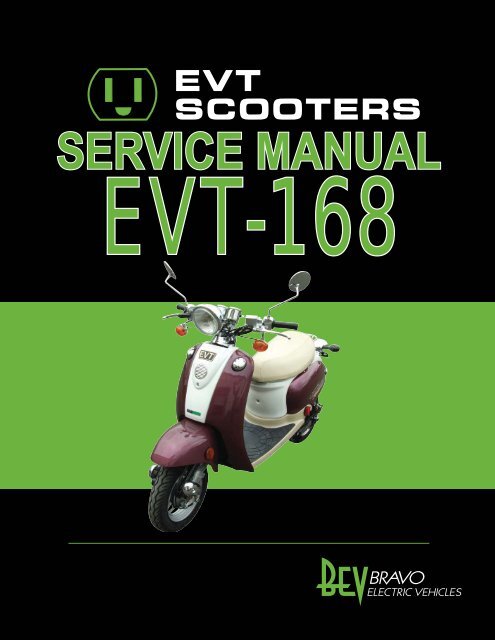
SERVICE MANUAL<br />
<strong>EVT</strong>-<strong>168</strong>
1. Front Cover<br />
2. Seat<br />
3. Center Cover<br />
4. Left Side Cover<br />
5. Right Side Cover<br />
6. Footrest Board<br />
7. Tail Bracket<br />
8. Rear Body Cover<br />
9. Lower Cover<br />
10. Fairing<br />
11. Front Fender<br />
12. Rear Fender<br />
13. Head Lamp Bulb<br />
14. Front Direction Lamp Bulb<br />
15. Tail Lamp Bulb<br />
16. Rear Direction Lamp Bulb<br />
17. Main Switch<br />
18. Seat Lock Assembly<br />
19. Horn<br />
20. Flasher Relay<br />
21. DC to DC Converter<br />
22. Controller<br />
Table of Contents<br />
23. Rear Shock Absorber<br />
24. Rear Caliper<br />
25. Brake Master Cylinder<br />
26. Brake Hose<br />
27. Brake Fluid<br />
28. Brake Pad<br />
29. Direct Driven Hub-Motor<br />
30. Brake Disk<br />
31. Rear Fork<br />
32. Front Shock Absorber<br />
33. Head Lamp<br />
34. Front Direction Lamp<br />
35. Current Meter and Speedometer<br />
36. Left Handle Switch<br />
37. Right Handle Switch<br />
38. Tail Lamp Assembly<br />
39. Front Brake Cable<br />
40. Throttle Cable<br />
41. Handle<br />
42. Steering Bracket<br />
43. Front Fork and Ball Race<br />
44. Part Summary
Tools Required: Phillips screwdriver<br />
Time: Allow 10 minutes for procedure<br />
1. Release the screw on the front cover.<br />
Front Cover<br />
2. Release four screws on the back of the front cover.<br />
3. Remove the front cover.<br />
4. Follow with the reversed steps to restore.<br />
1
2<br />
Tools Required: T-bend socket wrench, 10mm<br />
Time: Allow 10 minutes for procedure<br />
1. Release two nuts on the seat.<br />
2. Remove the seat.<br />
3. Follow with the reversed steps to restore.<br />
Seat
Tools Required: T-bend socket wrench, 8mm<br />
Time: Allow 10 minutes for procedure<br />
1. Release the screw on the center cover.<br />
2. Remove the center cover.<br />
3. Follow with the reversed steps to restore.<br />
Center Cover<br />
3
4<br />
Tools Required: Phillips screwdriver<br />
Time: Allow 10 minutes for procedure<br />
1. Remove the center cover.<br />
2. Release four screws on the left side cover.<br />
3. Remove the left side cover.<br />
4. Follow with the reversed steps to restore.<br />
Left Side Cover
Tools Required: Phillips screwdriver<br />
Time: Allow 10 minutes for procedure<br />
1. Release the screw on the cover.<br />
Right Side Cover<br />
2. Remove the cover.<br />
3. Release four screws on the right side cover.<br />
4. Remove the right side cover.<br />
5
6<br />
Tools Required: T-bend socket wrench, 10mm<br />
Time: Allow 10 minutes for procedure<br />
1. Release four screws on the footrest board.<br />
2. Remove the footrest board.<br />
3. Follow with the reversed steps to restore.<br />
Footrest Board
Tail Bracket<br />
Tools Required: Y-bend socket wrench, 10mm; hex-key wrench, 6mm<br />
Time: Allow 10 minutes for procedure<br />
1. Release the screw on the tail bracket.<br />
2. Release two nuts on the tail bracket.<br />
3. Remove the tail bracket.<br />
4. Follow with the reversed steps to restore.<br />
7
8<br />
Tools Required: Phillips screwdriver<br />
Time: Allow 10 minutes for procedure<br />
1. Release four screws on the rear cover.<br />
Rear Body Cover<br />
2. Remove the plastic cover on the seat lock.<br />
3. Release the 6-pin connector and 2-pin connectors.<br />
4. Remove the rear cover.<br />
5. Follow with the reversed steps to restore.
Tools Required: Phillips screwdriver<br />
Time: Allow 10 minutes for procedure<br />
Lower Cover<br />
1. Remove the footrest board and release the screw on the front of the lower cover.<br />
2. Remove the lower cover.<br />
3. Follow with the reversed steps to restore.<br />
9
10<br />
Tools Required: T-bend socket wrench, 8mm<br />
Time: Allow 10 minutes for procedure<br />
1. Remove the footrest board and the hanger on the back of the fairing.<br />
2. Remove the fairing.<br />
3. Follow with the reversed steps to restore.<br />
Fairing
Tools Required: Phillips screwdriver<br />
Time: Allow 10 minutes for procedure<br />
Front Fender<br />
1. Release three screws on the rear front fender.<br />
2. Release the screw on the top of the rear front fender and remove.<br />
3. Follow with the reversed steps to restore.<br />
11
12<br />
Tools Required: Phillips screwdriver<br />
Time: Allow 10 minutes for procedure<br />
Rear Fender<br />
1. Remove the right and left side covers and release two screws on the rear fender.<br />
2. Remove the rear fender.<br />
3. Follow with the reversed steps to restore.
Tools Required: Phillips screwdriver<br />
Time: Allow 10 minutes for procedure<br />
1. Release the screw on the head lamp ring.<br />
2. Release the head lamp ring.<br />
3. Release the spring on the bulb base.<br />
4. Remove the bulb base and replace the bulb.<br />
5. Follow with the reversed steps to restore.<br />
Head Lamp Bulb<br />
13
14<br />
Tools Required: Phillips screwdriver<br />
Time: Allow 10 minutes for procedure<br />
Front Direction Lamp Bulb<br />
1. Release the screw on the base of the direction lamp.<br />
2. Release ease the screw on the cover of the bulb. bul<br />
3. Replace the bulb and follow the reversed steps to restore.
Tools Required: Phillips screwdriver<br />
Time: Allow 10 minutes for procedure<br />
Tail Lamp Bulb<br />
1. Release two screws on the tail lamp cover and remove.<br />
2. Replace the light bulb.<br />
3. Follow the reversed steps to restore.<br />
15
16<br />
Tools Required: Phillips screwdriver<br />
Time: Allow 10 minutes for procedure<br />
Rear Direction Lamp Bulb<br />
1. Release the screw on the base of the direction lamp.<br />
2. Remove the cover of the direction lamp.<br />
3. Replace the bulb and follow the reversed steps to restore.
Tools Required: T-bend socket wrench, 10mm<br />
Time: Allow 10 minutes for procedure<br />
1. Remove front covers.<br />
2. Release the 4-pin connector.<br />
Main Switch<br />
3. Release two screws on the main switch and remove the key switch.<br />
4. Follow with the reversed steps to restore.<br />
17
18<br />
Tools Required: Phillips screwdriver<br />
Time: Allow 10 minutes for procedure<br />
1. Remove the rear body cover.<br />
2. Remove the seat box rim.<br />
3. Release two screws on the seat lock.<br />
4. Release two screws on the seat lock switch.<br />
5. Remove the seat lock and seat lock switch.<br />
6. Follow with the reversed steps to restore.<br />
Seat Lock Assembly
Tools Required: Open-end wrench, 10mm<br />
Time: Allow 10 minutes for procedure<br />
1. Remove the front cover.<br />
2. Release two connectors on the horn.<br />
3. Release the screw on the horn.<br />
4. Follow with the reversed steps to restore.<br />
Horn<br />
19
20<br />
Time: Allow 10 minutes for procedure<br />
Flasher Relay<br />
1. Remove the front cover.<br />
2. Release the 2-pin connector on the flasher relay.<br />
3. Follow with the reversed steps to restore.
Tools Required: Phillips screwdriver<br />
Time: Allow 10 minutes for procedure<br />
DC to DC Converter<br />
1. Remove the side covers and footrest board.<br />
2. Release the 4-pin connector for the converter.<br />
3. Release three screws on the converter.<br />
4. Follow with the reversed steps to restore.<br />
21
22<br />
Tools Required: Phillips screwdriver<br />
Time: Allow 10 minutes for procedure<br />
Controller<br />
1. Remove the right side cover.<br />
2. Release connectors of controller wire harness.<br />
3. Release the copper nut throttle cable and remove (replace with nail to prevent pillar<br />
drawing back).<br />
4. Release four screws on the controller, cut off band.<br />
5. Follow with reversed steps to restore.
Tools Required: T-bend socket wrench, 10mm<br />
Time: Allow 10 minutes for procedure<br />
Rear Shock Absorber<br />
1. Remove the rear body cover.<br />
2. Release two screws on the rear shock absorber.<br />
3. Follow with the reversed steps to restore.<br />
23
24<br />
Rear Caliper<br />
Tools Required: Box wrench; Y-bend socket wrench, 12mm<br />
Time: Allow 10 minutes for procedure<br />
1. Release the screw on the rear caliper. Avoid leaking fuel onto the pad.<br />
2. Release the screw on the pad.<br />
3. Release two mounting screws on the caliper.<br />
4. Follow with the reversed steps to restore.
Brake Master Cylinder<br />
Tools Required: Box wrench, 12mm; hex-key wrench, 5mm<br />
Time: Allow 10 minutes for procedure<br />
1. Check the fluid in reservoir for refuel or replace the brake fluid.<br />
2. Replace reservoir if leakage occurs, or if gasket fails or wears out.<br />
3. Release the screw on the brake hose.<br />
4. Release two screws on the reservoir.<br />
5. Release two connectors and remove the master cylinder.<br />
6. Follow with the reversed steps to restore.<br />
25
26<br />
Brake Hose<br />
Tools Required: Box wrench; diagonal cutting pliers<br />
Time: Allow 10 minutes for procedure<br />
1. Remove all the covers and fenders.<br />
2. Release the screw on the brake hose of the rear caliper. Avoid leaking fuel onto the pad.<br />
3. Release the screw on the brake hose of master cylinder.<br />
4. Cut off the band on the brake hose and remove.<br />
5. Follow with the reversed steps to restore.
Tools Required: Phillips screwdriver<br />
Time: Allow 10 minutes for procedure<br />
Brake Fluid<br />
1. Release two screws on the cover of the master cylinder.<br />
2. Place tube and fluid vacuum on the rear caliper’s screw.<br />
3. Pour brake fluid into the master cylinder.<br />
4. Release the screw on the rear caliper and operate the fluid vacuum.<br />
5. Pull the brake lever several times. Ensure brake is functioning normally and brake hose is<br />
free of air.<br />
6. Restore cover of master cylinder.<br />
27
28<br />
Tools Required: Y-bend socket wrench, 12mm<br />
Time: Allow 10 minutes for procedure<br />
1. Release the screw on the rear caliper.<br />
2. Remove the rear caliper.<br />
Brake Pad<br />
3. Remove the brake pad from the base of the caliper.<br />
4. Follow with the reversed steps to restore.
Direct Driven Hub-Motor<br />
Tools Required: Phillips screwdriver; open end wrench, 24mm<br />
Time: Allow 10 minutes for procedure<br />
1. Release three screws on the motor cord cover.<br />
2. Cut off the band.<br />
3. Release the black connector of the motor cord.<br />
4. Remove the rear caliper.<br />
5. Release two nutes for the motor shaft.<br />
6. Remove the orientation boards.<br />
7. Remove the motor.<br />
8. Follow with the reversed steps to restore.<br />
29
30<br />
Tools Required: Hex-key wrench, 6mm<br />
Time: Allow 10 minutes for procedure<br />
1. Remove the motor from the frame.<br />
2. Release three screws on the brake disk.<br />
3. Remove the brake disk.<br />
4. Follow with the reversed steps to restore.<br />
Brake Disk
Tools Required: Box wrench, 17mm<br />
Time: Allow 10 minutes for procedure<br />
Rear Fork<br />
1. Remove the rear caliper, rear motor, and rear shock absorber.<br />
2. Cut off the band on the brake hose and release the screw on the rear fork.<br />
3. Remove the rear fork.<br />
4. Follow with the reversed steps to restore.<br />
31
32<br />
Front Shock Absorber<br />
Tools Required: Phillips screwdriver; Y-bend socket wrench, 12mm<br />
Time: Allow 10 minutes for procedure<br />
1. Remove the front fender.<br />
2. Release the screw on the front fork cover and remove.<br />
3. Release two screws on the front shock absorber and remove.<br />
4. Follow with the reversed steps to restore.
Tools Required: Box wrench, 14mm<br />
Time: Allow 10 minutes for procedure<br />
1. Remove the front cover.<br />
2. Release the 6-pin connector.<br />
3. Release the screw on the head lamp holder.<br />
4. Follow with the reversed steps to restore.<br />
Head Lamp<br />
33
34<br />
Tools Required: Phillips screwdriver<br />
Time: Allow 10 minutes for procedure<br />
Front Direction Lamp<br />
1. Remove the front cover.<br />
2. Release the 2-pin connector on the front direction lamp (Green, left; red, right).<br />
3. Release the screw on the handle switch and remove the direction lamp.<br />
4. Follow with the reversed steps to restore.
Current Meter and Speedometer<br />
Tools Required: T-bend socket wrench, 8mm<br />
Time: Allow 10 minutes for procedure<br />
1. Remove the front cover.<br />
2. Release the 6-pin connector and the 2-pin connector on the meters.<br />
3. Release two screws on the instrument panel.<br />
4. Release the nut for the speedometer and remove the instrument panel.<br />
5. Follow with the reversed steps to restore.<br />
35
36<br />
Tools Required: Phillips screwdriver<br />
Time: Allow 10 minutes for procedure<br />
Left Handle Switch<br />
1. Remove the front cover.<br />
2. Release all connectors for the left handle switch.<br />
3. Release two screws on the left handle switch.<br />
4. Follow with the reversed steps to restore.
Tools Required: Phillips screwdriver<br />
Time: Allow 10 minutes for procedure<br />
Right Handle Switch<br />
1. Remove the front cover.<br />
2. Release all connectors for the right handle switch.<br />
3. Release two screws on the right handle switch.<br />
4. Follow with the reversed steps to restore.<br />
37
38<br />
Tools Required: Open-end wrench, 10mm<br />
Time: Allow 10 minutes for procedure<br />
Tail Lamp Assembly<br />
1. Remove the rear fender.<br />
2. Release the three screws on the base of the tail lamp assembly.<br />
3. Release all connectors for the tail lamp assembly.<br />
4. Follow with the reversed steps to restore.
Time: Allow 10 minutes for procedure<br />
Front Brake Cable<br />
1. Remove the front cover.<br />
2. Release the adjusting bolt on the brake cable and pull out the brake cable<br />
3. Remove the brake cable from the brake cable head.<br />
4. Follow with the reversed steps to restore.<br />
39
40<br />
Tools Required: Phillips screwdriver<br />
Time: Allow 10 minutes for procedure<br />
Throttle Cable<br />
1. Follow page 22 ( step 1 to step 3) to pull the throttle pillar out.<br />
2. Follow page 37 ( step 1 to step 3) to remove the handle switch.<br />
3. Remove the throttle cable head on the handle grip.<br />
4. Release the screw on the right handle switch.<br />
5. Remove the throttle cable.<br />
6. Follow with the reversed steps to restore.
Tools Required: hex-key wrench (5mm)<br />
Time: Allow 10 minutes for procedure<br />
Handle<br />
1. Remove the instrument panel, handle switches (right and left) and brake master cylinder.<br />
2. Release four screws on the handle Clamp.<br />
3. Remove the handle.<br />
4. Follow with the reversed steps to restore.<br />
41
42<br />
Steering Bracket<br />
Tools Required: Phillips screwdriver, box wrench (14mm)<br />
Time: Allow 10 minutes for procedure<br />
1. Remove handle.<br />
2. Release the screw on the steering bracket cover.<br />
3. Remove the steering bracket cover.<br />
4. Release the screw on the steering bracket.<br />
5. Remove the steering bracket.<br />
6. Follow with the reversed steps to restore.
Front Fork and Ball Race<br />
Tools Required: open-end wrench (32mm, 45mm)<br />
Time: Allow 10 minutes for procedure<br />
1. Remove front covers, instrument panel, head lamp, handle and steering bracket.<br />
2. Remove front wheel.<br />
3. Release the nut on the ball race and check the steel balls to see if they are missing.<br />
4. Properly adjust the front fork clearance and follow with the reversed steps to restore.<br />
43
44<br />
FIG.01 FRONT WHEEL<br />
Item NO. Part NO. Description Qty.<br />
1 0268-01003501 RIM, FRONT 1<br />
2 0268-01005500 FRONT WHEEL ASSEMBLY 1<br />
3 6277-100105 DRUM BRAKE COMP., FRONT 1<br />
4 0<strong>168</strong>-01001300 SHAFT, FRONT FORK 1<br />
5 6278-100205 COVER, SHAFT 1<br />
6 0268-0100550A DUST COVER (LARGE) 1<br />
7 0268-0100550B DUST COVER (SMALL) 4<br />
8 0268-01006500 COVER, METER GEAR 1<br />
9 0268-01002900 SCREW, SHAFT 1<br />
10 0268-01003700 BEARING 2<br />
11 0268-04000300 OIL SEAL 1<br />
12 0268-01003800 COVER, FRONT RIM 1<br />
13 6270-30010 BRAKE PAD, DRUM BRAKE 2<br />
14 6240-00001 TIRE, TUBELESS 1<br />
15 0241-10601 TIRE VALVE 1<br />
16 6148-100104 COLLAR, F. WHEEL 1<br />
16 0268-10514001 BOLT, HEX./FLANGE 1<br />
Part Summary
FIG.02 FORK<br />
Item NO. Part NO. Description Qty.<br />
1 0268-01003601 FRONT FORK 1<br />
2 0<strong>168</strong>-01001300 SWING ARM SET, LEFT & RIGHT 1<br />
3 0268-010046A1 SHOCK ABSORBER, FRONT 2<br />
4 6112-080358 SCREW, HEX./FLANGE 4<br />
5 6141-080758 NUT, HEX./FLANGE 2<br />
6 0268-01003400 RACE, BALL SET 1<br />
7 0268-30201 CHROME COVER, L. CUSHION 2<br />
8 6127-061511 SCREW, PAN/+ 2<br />
Part Summary (cont’d)<br />
45
46<br />
FIG.03 REAR WHEEL<br />
Item NO. Part NO. Description Qty.<br />
1 02A9-05000101 MOTOR ASSY. 1<br />
2 0241-20201 BRAKE DISC, REAR 1<br />
3 6240-00001 TIRE, TUBELESS 1<br />
4 6109-080201 SCREW, BRAKE DISC 3<br />
5 0241-10601 TIRE VALVE 1<br />
6 6248-00001 CONNECTOR, BLACK 1<br />
7 0268-01005901 REAR FORK SET 1<br />
8 6113-103001 BOLT (M10*300) 1<br />
9 6143-100801 NUT, DOME (M10 *8) 1<br />
10 6150-1030305 PLAIN WASHER 4<br />
11 0299-01001501 SHOCK ABSORBER, REAR 2<br />
12 6112-080358 BOLT, HEX. FLANGE 2<br />
13 6111-100407 BOLT, HEX. FLANGE 2<br />
14 0268-30501 CALIPER, REAR 1<br />
15 6112-080<strong>168</strong> SCREW, HEX. FLANGE 2<br />
16 0299-010016C3 COVER, MOTOR CORD 1<br />
17 6126-041001 SCREW, PAN 3<br />
18 6141-100908 NUT, HEX./FLANGE 2<br />
19 6151-0815208 SPRING WASHER 2<br />
20 6274-100110 BRACKET, REAR FENDER. (Left) 1<br />
21 6274-110110 BRACKET, REAR FENDER. (Right) 1<br />
22 0299-24000100 REAR FENDER 1<br />
Part Summary (cont’d)
FIG.04 FRAME<br />
Item NO. Part NO. Description Qty.<br />
1 0268-01001100 FRAME 1<br />
2 6266-100104 MAIN STAND 1<br />
3 6111-081255 BOLT (M8*125) 1<br />
4 6142-080855 NUT, FLANGE (M8) 1<br />
5 0268-50301 SPRING, MAIN STAND 2<br />
6 6266-200103 SIDE STAND 1<br />
7 0268-05002200 LOCK SET 1<br />
8 6112-060146 SCREW, HEX. FLANGE (M6*14) 2<br />
9 0268-01004702 TAIL BRACKET 1<br />
10 6100-080201 SCREW, SOCKET (M8*20) 1<br />
11 6144-060601 NUT, DOME (M6) 2<br />
Part Summary (cont’d)<br />
47
48<br />
FIG.05 CONTROLLER<br />
Item NO. Part NO. Description Qty.<br />
1 0268-05002802 CONTROLLER (DOT) 1<br />
2 6126-052005 SCREW, PAN HEAD (M5*20) 4<br />
3 6255-00001 HORN 1<br />
4 6112-060126 SCREW, HEX. FLANGE (M6*12) 1<br />
5 0268-05003000 FLASHER RELAY(DOT) 1<br />
6 0268-05002300 DC/DC CONVERTER (DOT) 1<br />
7 0268-05000101 MAIN CONTROL CORD (DOT) 1<br />
8 6256-00200 TIE BAND, Medium 7<br />
9 6256-00280 TIE BAND, Long 3<br />
10 6126-051031 SCREW, PAN HEAD (M5*10) 2<br />
11 0299-01001700 THROTTLE CABLE 1<br />
Part Summary (cont’d)
FIG.06 HANDLE BAR<br />
Item NO. Part NO. Description Qty.<br />
1 0268-42301 STEERING BRACKET 1<br />
2 6111-100407 SCREW, HEX./FLANGE 1<br />
3 6141-100908 NUT, HEX./FLANGE 1<br />
4 0268-42401 CHROME COVER, STRG. BRACKET 1<br />
5 0268-01001600 LOWER HANDLE CLAMP 2<br />
6 0268-40101 HANDLE 1<br />
7 0268-01001700 UPPER HANDLE CLAMP, LEFT 1<br />
8 0268-01001800 UPPER HANDLE CLAMP, RIGHT 1<br />
9 0268-05001900 HANDLE SWITCH, LEFT 1<br />
10 0268-05002001 HANDLE SWITCH, RIGHT (DOT) 1<br />
11 0268-40900 MASTER CYLINDER, LEFT 1<br />
12 6283-200141 BRAKE HOSE, REAR 1<br />
13 0241-41901 SCREW, BRAKE HOSE 2<br />
14 0241-41902 WASHER, BRAKE HOSE 4<br />
15 0268-05003201 FRONT WINKER, RIGHT (DOT) 1<br />
16 0268-05003200 FRONT WINKER, LEFT (DOT) 1<br />
17 0241-41402 BRACKET, LEFT WINKER 1<br />
18 0241-41404 BRACKET, RIGHT WINKER 1<br />
19 6126-051031 SCREW, PAN/+ 2<br />
20 6170-100110 HANDLE GRIP, LEFT 1<br />
21 6170-100210 HANDLE GRIP, RIGHT 1<br />
22 0268-01005300 REAR VIEW MIRROR SET 1<br />
23 0268-01005600 BRAKE LEVER, LEFT 1<br />
24 0268-01004801 BRAKE LEVER, RIGHT 1<br />
Part Summary (cont’d)<br />
49
50<br />
FIG.07 METER/HEAD LIGHT<br />
Item NO. Part NO. Description Qty.<br />
1 0268-42601 BRACKET, METER ASSY. 1<br />
2 0268-425011 BRACKET, HEADLIGHT 1<br />
3 6141-060608 NUT, HEX./FLANGE 2<br />
4 0268-05003100 HEADLIGHT COMP. (DOT) 1<br />
5 6113-080406 SCREW, HEX./FLANGE 1<br />
6 6141-080756 NUT, HEX./FLANGE 1<br />
7 0268-050025A1 CURRENT METER 1<br />
8 0268-05002601 SPEEDOMETER (DOT) 1<br />
9 0268-01004100 COPPER COVER 4<br />
10 0268-04000400 RUBBER COVER 4<br />
11 0268-014000211 NUT, HEX./FLANGE 4<br />
12 6112-060146 SCREW, HEX./FLANGE 2<br />
13 0268-41704 CABLE, SPEEDOMETER 1<br />
Part Summary (cont’d)
FIG.08 TAIL LAMP<br />
Item NO. Part NO. Description Qty.<br />
1 6263-210102 TAIL LAMP COVER 1<br />
2 6263-21101 TAIL LAMP 1<br />
3 6276-200161 PLATE, LICENCE PLATE 1<br />
4 0268-05003300 DIRECTIONAL LAMP, REAR (L) (DOT) 1<br />
5 0268-05003301 DIRECTIONAL LAMP, REAR (R) (DOT) 1<br />
6 0268-71104 MOUNTING PLATE, TAIL LAMP 1<br />
7 0268-71701 REAR FENDER 1<br />
8 6246-10002 REFLECTOR 1<br />
9 6112-060146 SCREW, HEX./FLANGE 2<br />
10 6141-0804758 NUT, HEX./FLANGE 2<br />
11 6113-0603561 SCREW, HEX./FLANGE 3<br />
12 6141-060606 NUT, HEX./FLANGE 3<br />
13 6141-080758 NUT, HEX./FLANGE 2<br />
14 6144-060606 NUT, HEX./FLANGE 2<br />
Part Summary (cont’d)<br />
51
52<br />
FIG.09 SEAT<br />
Item NO. Part NO. Description Qty.<br />
1 0268-70101 SEATBOX RIM 1<br />
2 0268-01004900 SEAT HINGE 1<br />
3 6112-060126 SCREW, HEX./FLANGE 2<br />
4 0268-24000200 SEAT 1<br />
5 0268-01004910 PIN, SEAT 1<br />
6 0268-72301 BRACKET, SEAT 1<br />
7 6141-060608 NUT, HEX./FLANGE 2<br />
Part Summary (cont’d)
FIG.10 FRONT COVER<br />
Item NO. Part NO. Description Qty.<br />
1 0268-13003001 FAIRING (LIGHT BLUE) 1<br />
0268-13003002 FAIRING (LIGHT ORANGE) 1<br />
0268-13003003 FAIRING (DARK GREEN) 1<br />
0268-13003004 FAIRING (PURPLE RED) 1<br />
2 0268-70891 R. PLUG, FAIRING 1<br />
3 0268-70892 L. PLUG CAP, FAIRING 1<br />
4 0268-70893 HANGER, SIDE 2<br />
5 6127-061511 SCREW, PAN/+ 1<br />
6 6269-210161 FRONT TRIM CAP, LEFT 1<br />
7 6269-210261 FRONT TRIM CAP, RIGHT 1<br />
8 6132-501511 SCREW, TAPPING/+ 8<br />
9 6112-060126 SCREW, HEX. FLANGE 1<br />
10 0268-70701 FRONT COVER 1<br />
11 0268-70702 EMBLEM CAP, <strong>EVT</strong> 1<br />
12 0268-70703 HORN COVER 1<br />
13 0268-71601 F. FENDER, FRONT (LIGHT BLUE) 1<br />
0268-71608 F. FENDER, FRONT (LIGHT ORANGE) 1<br />
0268-71605 F. FENDER, FRONT (DARK GREEN) 1<br />
0268-71604 F. FENDER, FRONT (PURPLE RED) 1<br />
14 0268-71611 F. FENDER, REAR (LIGHT BLUE) 1<br />
0268-71618 F. FENDER, REAR (LIGHT ORANGE) 1<br />
0268-71615 F. FENDER, REAR (DARK GREEN) 1<br />
0268-71614 F. FENDER, REAR (PURPLE RED) 1<br />
15 0268-24000101 REFLECTOR (AMBER) 2<br />
16 6112-060146 SCREW, HEX./FLANGE 1<br />
Part Summary (cont’d)<br />
53
54<br />
FIG.11 SIDE COVER<br />
Item NO. Part NO. Description Qty.<br />
1 0268-70501 LEFT COVER (LIGHT BLUE) 1<br />
0268-70508 LEFT COVER (LIGHT ORANGE) 1<br />
0268-70505 LEFT COVER (DARK GREEN) 1<br />
0268-70504 LEFT COVER (PURPLE RED) 1<br />
2 0268-70601 RIGHT COVER (LIGHT BLUE) 1<br />
0268-70608 RIGHT COVER (LIGHT ORANGE) 1<br />
0268-70605 RIGHT COVER (DARK GREEN) 1<br />
0268-70604 RIGHT COVER (PURPLE RED) 1<br />
3 6269-200361 OUTER TRIM CAP, L. COVER 1<br />
4 6269-200461 OUTER TRIM CAP, R. COVER 1<br />
5 6132-501511 SCREW, TAPPING/+ 13<br />
6 0268-71402 REAR BODY COVER, WHITE 1<br />
7 6258-101001 STICKER, SIDE COVER 1<br />
6258-101002 STICKER, SIDE COVER 1<br />
8 0268-72401 TRIM CAP, REAR FENDER 1<br />
Part Summary (cont’d)
FIG.12 FOOTREST BOARD<br />
Item NO. Part NO. Description Qty.<br />
1 0268-71303 FOOTREST BOARD, LIGHT BROWN 1<br />
2 6112-060126 SCREW, HEX./FLANGE 4<br />
3 0268-71401 FRONT BODY COVER, WHITE 1<br />
0268-13001309 FRONT BODY COVER, SILVER 1<br />
4 0268-70102 COVER, LOWER 1<br />
5 6127-061511 SCREW, HEX./FLANGE 2<br />
6 6113-0603561 SCREW, HEX./FLANGE 1<br />
7 6150-0613105 WASHER 1<br />
8 0268-24000101 REFLECTOR(RED) (DOT) 2<br />
9 6282-100161 FLOOR MAT 1<br />
Part Summary (cont’d)<br />
55
56<br />
FIG.13 BATTERY<br />
Item NO. Part NO. Description Qty.<br />
1 181-460-10 BATTERY, LEV 12500 4<br />
2 6261-040621 BATTERY CORD SET, LONG 1<br />
6261-050621 BATTERY CORD SET, SHORT 3<br />
3 0299-05000400 CONNECTION CABLE, BATTERY 1<br />
4 6243-100119 CHARGER 1<br />
Part Summary (cont’d)
Accessories<br />
Item NO. Part NO. Description<br />
1 0268-24000301 STORAGE CASE, LIGHT BLUE<br />
2 0268-24000302 STORAGE CASE, LIGHT ORANGE<br />
3 0268-24000303 STORAGE CASE, DARK GREEN<br />
4 0268-24000304 STORAGE CASE, PURPLE RED<br />
5 0268-24000309 STORAGE CASE, SILVER<br />
6 0268-01004702 <strong>EVT</strong>-<strong>168</strong> CARGO CASE BRACKET<br />
7 0268-13000408 FRONT FENDER, CHROME<br />
8 0241-80901 FRONT BASKET<br />
9 0241-305211 BRAKE PAD, BLUE (UNCUT)<br />
10 0268-41002 BRAKE CABLE, FRONT (1206MM)<br />
11 0242-41001 BRAKE CABLE, REAR<br />
12 745-956-20-006 EV-500 SOLAR CHARGER<br />
13 875-738-20-001 WIRE KIT W/CONNECTOR FOR EV-500<br />
14 PB-360P-48 LITHIUM BATTERY CHARGER<br />
15 0241-80821 WINDSHIELD<br />
16 0241-808022 WINDSHIELD - ASSEMBLY KIT<br />
17 02A9-05000400 MOTOR BRUSH 8PC SET (BEFORE 2006)<br />
18 02A9-05000500 MOTOR BRUSH 16PC SET (2006-2008)<br />
19 6257-101500 REFURBISHED MOTOR (BRUSH - MODELS THROUGH 2008)<br />
57


