Replacement Burner Tube Insulator and Combustion Chamber Liner
Replacement Burner Tube Insulator and Combustion Chamber Liner
Replacement Burner Tube Insulator and Combustion Chamber Liner

Create successful ePaper yourself
Turn your PDF publications into a flip-book with our unique Google optimized e-Paper software.
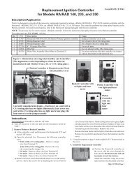
Instructions for Installing <strong>Replacement</strong> <strong>Liner</strong> (cont’d)<br />
4. Install the <strong>Chamber</strong> Sleeve (Refer to Figures 5 <strong>and</strong> 6) - Position<br />
the liner sleeve into the chamber with the front edge as close as<br />
possible to the front edge of the chamber. (NOTES: In Sizes 235<br />
<strong>and</strong> 500 a portion of the rear section of the chamber is not covered.<br />
In Sizes 350 <strong>and</strong> 500, a second liner sleeve will fill in the<br />
“gap” between the chamber opening <strong>and</strong> the door.) Starting at<br />
the bottom <strong>and</strong> working up, mold the liner to the chamber. After the<br />
entire liner is molded to the chamber, work upwards again applying<br />
more pressure.<br />
Figure 5 - Position the liner sleeve so that the front<br />
edge is as close as possible to the front edge of the<br />
chamber. Working from the bottom up, mold the liner<br />
to the combustion chamber.<br />
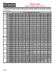
When the liner is molded properly, the shape of each boiler section<br />
will be apparent through the liner. Use the narrow b<strong>and</strong>s of steel<br />
supplied with the boiler to support the liner until it has been heated<br />
<strong>and</strong> dried. Being careful not to cut through, push the ends of the<br />
b<strong>and</strong>s into the liner to keep them in place.<br />
Figure 6 - The back plate liner <strong>and</strong> the chamber sleeve<br />
liner are installed. Use the metal b<strong>and</strong>s supplied with<br />
the boiler to hold the liner sleeve in place.<br />
If the unit is a Size 350 or 500, proceed to Step 5. If the unit is a Size<br />
140 or 235, the liner is ready to dry; skip Step 5 <strong>and</strong> go directly to Step<br />
6.<br />
Form CP-W44, Page 2<br />
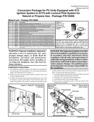
5. Install the “Opening” <strong>Liner</strong> Sleeve - Sizes 350 <strong>and</strong> 500 only<br />
(See Figures 7 <strong>and</strong> 8) - Position the liner so that it is flush with the<br />
front opening. Mold the liner starting at the bottom <strong>and</strong> working<br />
from front to back. Keep the outer edge even with the opening <strong>and</strong><br />
mold any excess liner material toward the chamber liner.<br />
Figure 7 - Position the “opening” liner sleeve with the<br />
outer edge even with the front opening.<br />
Figure 8 - Mold the liner starting at the bottom <strong>and</strong><br />
working from the front toward the back. Keep the outer<br />
edge even with the opening; mold any “excess” over the<br />
edge of the chamber liner.<br />
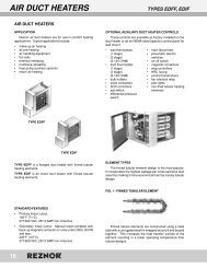
6. Install the <strong>Burner</strong> <strong>Tube</strong> <strong>Insulator</strong> (See Figure 9)<br />
a) Rotate the old burner tube insulator until the screws line up<br />
with the slots in the insulator. Slide the insulator off of the burner<br />
tube <strong>and</strong> discard.<br />
b) Clean the end cone being careful not to move or damage the<br />
burner parts. Vacuum any particles.<br />
c) Align the slots in the inside of the new insulator to the screw<br />
heads on the end cone. Slide the insulator over the end cone<br />
until it is flush with the opening. Rotate the insulator approximately<br />
1” to lock it in place.