Replacement Burner Tube Insulator and Combustion Chamber Liner
Replacement Burner Tube Insulator and Combustion Chamber Liner
Replacement Burner Tube Insulator and Combustion Chamber Liner

You also want an ePaper? Increase the reach of your titles
YUMPU automatically turns print PDFs into web optimized ePapers that Google loves.
Form RGM CP-W44<br />
<strong>Replacement</strong> <strong>Burner</strong> <strong>Tube</strong> <strong>Insulator</strong><br />
<strong>and</strong> <strong>Combustion</strong> <strong>Chamber</strong> <strong>Liner</strong> Kit for<br />
Models RAB 140, 235, 350, <strong>and</strong> 500<br />
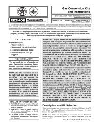
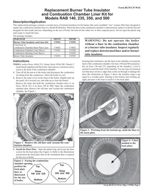
Description/Application<br />
This replacement packages contains a circular piece of formed insulation for the burner tube <strong>and</strong> a moldable “wet” ceramic fiber liner designed to<br />
replace the combustion chamber liner in a Model RAB boiler. When the liner in the combustion chamber is deteriorated, replace it with the liner kit<br />
designed for that model <strong>and</strong> size. Depending on the size of boiler, the liner kit has either two or three separate pieces. Do not open the plastic bag<br />
until ready to install the liner.<br />
The package includes:<br />
Model RAB 140/235 350/500<br />
<strong>Burner</strong> <strong>Tube</strong> <strong>Insulator</strong> <strong>and</strong> <strong>Liner</strong> Kit 175994 175995<br />
Consisting of:<br />
<strong>Combustion</strong> <strong>Chamber</strong> Back Plate <strong>Liner</strong> 174682 174682<br />
<strong>Combustion</strong> <strong>Chamber</strong> <strong>Liner</strong> Sleeve 174701 174700<br />
<strong>Combustion</strong> Opening <strong>Liner</strong> Sleeve -- 174702<br />
<strong>Burner</strong> <strong>Tube</strong> <strong>Insulator</strong> 174703 174703<br />
Instructions<br />
TOOLS: socket (Sizes 140 & 235, 16mm; Sizes 350 & 500, 18mm); 3<br />
metal b<strong>and</strong>s supplied with the boiler; latex gloves; extension tool to<br />
reach to the back of the combustion chamber<br />
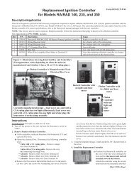
1. Turn off all the power to the boiler <strong>and</strong> disconnect the combustion<br />
air tubing from the compressor. Allow the boiler to cool.<br />
2. Remove the outer cover on the front of the boiler. Slightly pick up<br />
the panel, tilt it toward you, <strong>and</strong> slide up to clear the burner.<br />
Remove the bolts that hold the combustion chamber door (2 on<br />
Sizes 140 & 235; 4 on Sizes 350 & 500). Open the combustion<br />
chamber door. Remove the old liner <strong>and</strong> vacuum the combustion<br />
chamber. See Figure 1.<br />
Figure 1 - Remove the old liner <strong>and</strong> vacuum the combustion<br />
chamber.<br />
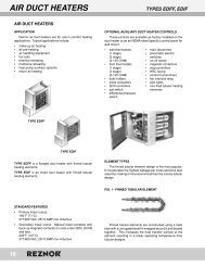
3. Install the Back Plate - Open the plastic bag <strong>and</strong> locate the liner<br />
section for the back plate (See Figure 2). Refer to the illustrations<br />
<strong>and</strong> position the back plate liner in the orientation that is required<br />
for the size of boiler.<br />
Figure 2 - Facing the combustion<br />
chamber opening,<br />
position the<br />
back plate<br />
liner as<br />
illustrated<br />
for the size<br />
of boiler.<br />
Top<br />
Sizes<br />
140 <strong>and</strong> 235<br />
Bottom<br />
Top<br />
Sizes<br />
350 <strong>and</strong> 500<br />
Bottom<br />
WARNING: Do not operate the boiler<br />
without a liner in the combustion chamber<br />
or a burner tube insulator. Inspect regularly<br />
<strong>and</strong> replace deteriorated liner <strong>and</strong>/or burner<br />
tube insulator.<br />
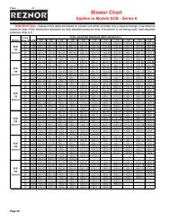
Keeping that orientation, put the liner in the chamber covering the<br />
back of the combustion chamber. On Sizes 350 <strong>and</strong> 500 (<strong>and</strong> possibly<br />
on Sizes 140 <strong>and</strong> 235, depending on the installer), a tool is<br />
needed to reach the back of the chamber. Use any type of extension<br />
tool that does not have edges that could cut through or damage the<br />
liner (the illustration in Figure 3 shows the installer using a rag<br />
taped to a wooden pole). Starting at the bottom <strong>and</strong> working up,<br />
apply pressure to the liner to mold it to the back plate.<br />
Figure 3 - Working from the bottom up, mold the liner to<br />
the back plate.<br />
Figure 4 - <strong>Liner</strong><br />
molded to the<br />
back plate.<br />
Form RGM CP-W44, Mfg # 175996, Page 1
Instructions for Installing <strong>Replacement</strong> <strong>Liner</strong> (cont’d)<br />
4. Install the <strong>Chamber</strong> Sleeve (Refer to Figures 5 <strong>and</strong> 6) - Position<br />
the liner sleeve into the chamber with the front edge as close as<br />
possible to the front edge of the chamber. (NOTES: In Sizes 235<br />
<strong>and</strong> 500 a portion of the rear section of the chamber is not covered.<br />
In Sizes 350 <strong>and</strong> 500, a second liner sleeve will fill in the<br />
“gap” between the chamber opening <strong>and</strong> the door.) Starting at<br />
the bottom <strong>and</strong> working up, mold the liner to the chamber. After the<br />
entire liner is molded to the chamber, work upwards again applying<br />
more pressure.<br />
Figure 5 - Position the liner sleeve so that the front<br />
edge is as close as possible to the front edge of the<br />
chamber. Working from the bottom up, mold the liner<br />
to the combustion chamber.<br />
When the liner is molded properly, the shape of each boiler section<br />
will be apparent through the liner. Use the narrow b<strong>and</strong>s of steel<br />
supplied with the boiler to support the liner until it has been heated<br />
<strong>and</strong> dried. Being careful not to cut through, push the ends of the<br />
b<strong>and</strong>s into the liner to keep them in place.<br />
Figure 6 - The back plate liner <strong>and</strong> the chamber sleeve<br />
liner are installed. Use the metal b<strong>and</strong>s supplied with<br />
the boiler to hold the liner sleeve in place.<br />
If the unit is a Size 350 or 500, proceed to Step 5. If the unit is a Size<br />
140 or 235, the liner is ready to dry; skip Step 5 <strong>and</strong> go directly to Step<br />
6.<br />
Form CP-W44, Page 2<br />
5. Install the “Opening” <strong>Liner</strong> Sleeve - Sizes 350 <strong>and</strong> 500 only<br />
(See Figures 7 <strong>and</strong> 8) - Position the liner so that it is flush with the<br />
front opening. Mold the liner starting at the bottom <strong>and</strong> working<br />
from front to back. Keep the outer edge even with the opening <strong>and</strong><br />
mold any excess liner material toward the chamber liner.<br />
Figure 7 - Position the “opening” liner sleeve with the<br />
outer edge even with the front opening.<br />
Figure 8 - Mold the liner starting at the bottom <strong>and</strong><br />
working from the front toward the back. Keep the outer<br />
edge even with the opening; mold any “excess” over the<br />
edge of the chamber liner.<br />
6. Install the <strong>Burner</strong> <strong>Tube</strong> <strong>Insulator</strong> (See Figure 9)<br />
a) Rotate the old burner tube insulator until the screws line up<br />
with the slots in the insulator. Slide the insulator off of the burner<br />
tube <strong>and</strong> discard.<br />
b) Clean the end cone being careful not to move or damage the<br />
burner parts. Vacuum any particles.<br />
c) Align the slots in the inside of the new insulator to the screw<br />
heads on the end cone. Slide the insulator over the end cone<br />
until it is flush with the opening. Rotate the insulator approximately<br />
1” to lock it in place.
Figure 9 - Slide<br />
the burner<br />
insulator over<br />
the end cone<br />
until it is flush;<br />
rotate to lock.<br />
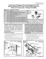
Figure 10A - <strong>Replacement</strong><br />
liner installed on a Model<br />
RAB 350 or 500<br />
Remove the b<strong>and</strong>s <strong>and</strong> save<br />
them for the next replacement<br />
liner installation.<br />
Back Plate <strong>Liner</strong><br />
<strong>Chamber</strong> <strong>Liner</strong><br />
Opening <strong>Liner</strong><br />
Figure 10B - <strong>Replacement</strong><br />
liner installed on a Model<br />
RAB 140 or 235<br />
Back Plate <strong>Liner</strong><br />
<strong>Chamber</strong> <strong>Liner</strong><br />
Installation of the replacement kit is complete.<br />
o Close <strong>and</strong> bolt the door. Replace the outer cover.<br />
o Reconnect the compressed air hose.<br />
o Turn on the power.<br />
7. Dry the <strong>Liner</strong> - Close the chamber access door <strong>and</strong> bolt it shut. Turn on<br />
the power <strong>and</strong> reconnect the compressed air. Start up the unit (NOTE: A<br />
ten-minute delay may occur before firing depending on the preheated oil<br />
temperature.) <strong>and</strong> fire it for at least ten minutes to completely dry the liner.<br />
Turn down the thermostat until the unit shuts down; turn off all power to<br />
the unit; disconnect the compressed air hose; allow the boiler to cool down;<br />
<strong>and</strong> open the access door.<br />
Inspect the liner. The liner must be rigid. If the liner is not hardened, repeat<br />
the drying procedure.<br />
When the combustion chamber replacement liner is rigid, remove the metal<br />
b<strong>and</strong>s <strong>and</strong> save them for installing the next replacement liner.<br />
o Turn the thermostat up to start the circulating pump.<br />
o Check for proper operation.<br />
Form RGM CP-W44, Mfg # 175996, Page 3
Form CP-W44, Page 4<br />
©1999 Thomas & Betts Corporation, All rights reserved. Printed in the U.S.A.<br />
MANUFACTURER OF GAS, OIL, ELECTRIC HEATING AND VENTILATING SYSTEMS<br />
Trademark Note: Reznor ® is registered in the United States <strong>and</strong> other countries.<br />
8/99 600 MForm CP-W44 (New)