Auxiliary Winding Switching Circuit for Single-Phase Induction Motors.
Auxiliary Winding Switching Circuit for Single-Phase Induction Motors.
Auxiliary Winding Switching Circuit for Single-Phase Induction Motors.

Create successful ePaper yourself
Turn your PDF publications into a flip-book with our unique Google optimized e-Paper software.
ABSTRACT<br />
<strong>Auxiliary</strong> <strong>Winding</strong> <strong>Switching</strong> <strong>Circuit</strong> <strong>for</strong> <strong>Single</strong>-<strong>Phase</strong> <strong>Induction</strong> <strong>Motors</strong>.<br />
I.A. Odigwe, MNSE, MIEEE, MIET * ; A.U. Adoghe, MNSE, MIEEE, MIET;<br />
A.A. Awelewa, MNSE, MIEEE; and I.A. Samuel, MNSE, R-Engr.<br />
Department of Electrical and In<strong>for</strong>mation Engineering, College of Science and Technology,<br />
Covenant University, Ota, PMB 1023, Ota, Ogun State, Nigeria.<br />
The most common practice <strong>for</strong> starting a singlephase<br />
induction motor is to connect a starting<br />
capacitor, in series, with the auxiliary winding.<br />
Here, the possibility of using an electronic switch<br />
in parallel with the starting capacitor, is discussed.<br />
This work relates particularly to a switching device<br />
<strong>for</strong> electrically connecting and removing the<br />
auxiliary winding and starting capacitor from the<br />
single-phase induction motor's circuitry. The<br />
starting capacitor with the auxiliary winding are<br />
disconnected by electronic means as the motor<br />
gains speed hence leaving only the main winding<br />
in the motor circuit <strong>for</strong> normal operation.<br />
(Keywords: centrifugal switch, auxiliary winding,<br />
electronic switch, induction motor, synchronous speed,<br />
starting capacitor)<br />
INTRODUCTION<br />
<strong>Single</strong>-phase motors are probably the most used<br />
AC motors today. It is logical that the least<br />
expensive, lowest maintenance type of AC motor<br />
should be used most often. The single-phase AC<br />
induction motor fits that description.<br />
Unlike polyphase induction motors, the stator field<br />
in the single-phase motor does not rotate. Instead<br />
it simply alternates polarity between poles as the<br />
AC voltage changes polarity. Voltage is induced in<br />
the rotor as a result of electromagnetic induction,<br />
and a magnetic field is produced around the rotor.<br />
This field will always be in opposition to the stator<br />
field (Lenz's law applies) [1]. The interaction<br />
between the rotor and stator fields will not<br />
produce rotation, however. Because this <strong>for</strong>ce is<br />
across the rotor and through the pole pieces,<br />
there is no rotary motion, just a push and/or pull<br />
along the magnetic lines.<br />
E-mail: iaodigwe@ieee.org<br />
<strong>Single</strong>-phase induction motors, typically comprise<br />
a distributed stator main winding, an auxiliary<br />
winding, and a squirrel-cage rotor. An AC supply<br />
voltage applied only to the stator winding creates<br />
a field fixed in space and alternating in<br />
magnitude. The field there<strong>for</strong>e produces no<br />
starting torque on the rotor. This condition,<br />
however, prevails only at rotor standstill. If, by<br />
some means, the rotor is started in either<br />
direction, it will develop a non-zero net torque in<br />
that direction and thereby cause the motor to<br />
approach its normal operating speed [1, 2].<br />
The typical non-mechanical method of starting a<br />
single phase induction motor is to temporarily<br />
include a second, auxiliary winding around the<br />
rotor to produce a revolving field of constant<br />
amplitude and constant linear velocity. This<br />
revolving field creates the necessary starting<br />
torque needed to start the rotor turning on its<br />
axis. To obtain this revolving field, the two<br />
windings are displaced in space by 90 electrical<br />
degrees. Additionally, the current flowing through<br />
these windings is time-displaced by 90 electrical<br />
degrees and the windings must have equal<br />
magnitude of mmfs [2].<br />
The space-displacement criterion is met by<br />
placing the auxiliary winding in the stator with its<br />
axis in quadrature with that of the main winding.<br />
Typically, the main winding occupies two-thirds of<br />
the stator slots, with the auxiliary winding<br />
occupying the remaining one-third [1, 2].<br />
The time displacement criterion regarding the<br />
currents through the two windings is at least<br />
partially obtained by designing the auxiliary<br />
winding <strong>for</strong> high resistance and low leakage<br />
reactance [2, 4]. This is in contrast to the main<br />
winding which typically has lower resistance and<br />
higher leakage reactance. Due to the highresistance<br />
characteristic and the short time<br />
power rating inherent in the auxiliary winding,<br />
The Pacific Journal of Science and Technology –324–<br />
http://www.akamaiuniversity.us/PJST.htm Volume 9. Number 2. November 2008 (Fall)
they must be removed from the supply once a<br />
sufficient percentage of normal operating speed is<br />
reached.<br />
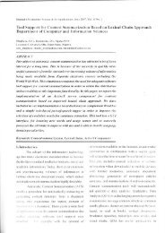
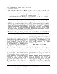
One method <strong>for</strong> removing the auxiliary winding<br />
and starting capacitor from the supply is by a cutoff<br />
switch, placed in the auxiliary winding circuit as<br />
shown in Figure 1, which by centrifugal action<br />
electrically removes the auxiliary winding and<br />
starting capacitor from the supply when the motor<br />
speed attains a certain percentage of<br />
synchronous speed. However, due to the large<br />
current flow and the switching action, the<br />
centrifugal switch contacts become damaged over<br />
time due to arcing [4]. This is disadvantageous<br />
because the auxiliary winding could burn itself out<br />
if the switch becomes faulty. Additionally, since<br />
the switch resides in the motor, it is difficult to<br />
miniaturize the overall motor size.<br />
Figure 1: Capacitor-Start, AC <strong>Induction</strong> Motor.<br />
Another method <strong>for</strong> removing the auxiliary winding<br />
from the supply involves replacing the centrifugal<br />
action switch with a 555 timer-based electronic<br />
circuit. This method will be fully discussed later in<br />
this paper.<br />
CENTRIFUGAL SWITCHING METHOD<br />
A centrifugal switch is an electric switch that<br />
operates using the centrifugal <strong>for</strong>ce created from<br />
a rotating shaft, most commonly that of an electric<br />
motor or car engine. The switch is designed to<br />
activate or de-activate as a function of the<br />
rotational speed of the shaft.<br />
The most common use of centrifugal switches is<br />
within single-phase, split-phase induction motors.<br />
Here, the switch is used to disconnect the starting<br />
winding and/or the starting capacitor of the<br />
single-phase induction motor once it approaches<br />
its normal operating speed. In this case, the<br />
centrifugal switch consists of weights mounted to<br />
the shaft of the motor and held near the shaft by<br />
spring <strong>for</strong>ces. At rest, levers attached to the<br />
weights press a low-friction, non-conductive plate<br />
against a set of electrical contacts mounted to the<br />
motor housing, closing the contacts and<br />
connecting the starting winding and capacitor to<br />
the power source. When the motor approaches<br />
its normal operating speed, centrifugal <strong>for</strong>ce<br />
overcomes the spring <strong>for</strong>ce and the weights<br />
swing out, raising the plate away from the<br />
electrical contacts. This allows the contacts to<br />
open and disconnect the starting winding from<br />
the power source; the motor then continues<br />
operating solely using its running winding.<br />
<strong>Motors</strong> using such a centrifugal switch make a<br />
distinct clicking noise when starting and stopping<br />
as the centrifugal switch opens and closes.<br />
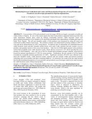
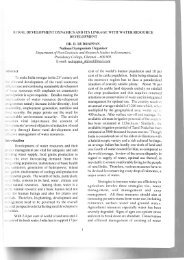
Figure 2 shows a cut-out view of a single-phase<br />
induction motor showing the position occupied by<br />
the centrifugal mechanism.<br />
Figure 2: Motor Interior View.<br />
ELECTRONIC SWITCHING APPROACH<br />
centrifugal<br />
mechanism<br />
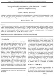
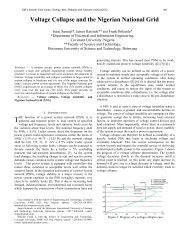
The circuit diagram <strong>for</strong> the electronic switching<br />
circuit is as shown in Figure 3. This is divided into<br />
5 units namely: the power supply, timer, amplifier,<br />
and relay circuits.<br />
The Pacific Journal of Science and Technology –325–<br />
http://www.akamaiuniversity.us/PJST.htm Volume 9. Number 2. November 2008 (Fall)
220-Vac<br />
Figure 3: The Electronic <strong>Switching</strong> <strong>Circuit</strong>.<br />
Power Supply <strong>Circuit</strong><br />
A 12-V trans<strong>for</strong>mer is used to deliver a regulated<br />
DC supply to the electronic switching circuit.<br />
Rectification was achieved with integrated circuit<br />
IN4001, a full-wave bridge rectification of the AC<br />
supply; and a 7812 three terminal integrated<br />
circuit <strong>for</strong> regulation with capacitors present <strong>for</strong><br />
filtering and transient compensation purposes as<br />
shown in Figure 4. Diode D2 is a power supply<br />
light emitting diode (LED) indicator with<br />
characteristic voltage drop in the <strong>for</strong>ward biased<br />
condition of 2V and sinks a maximum current of<br />
15mA. The current limiting resistor R4 is<br />
calculated using equations 1 and 2 [3].<br />
VR = VS – VD (1)<br />
where Vs = DC supply voltage<br />
VD = Diode voltage drop<br />
VR = Voltage across resistor, R4<br />
sw<br />
Timer <strong>Circuit</strong><br />
1000-µF<br />
0.01-µF<br />
7812<br />
Figure 4: Power Supply <strong>Circuit</strong>.<br />
(2)<br />
0.01-µF<br />
12-Vdc<br />
The timer circuit designed <strong>for</strong> the cutting-out<br />
process is a monostable multivibrator circuit, and<br />
when the trigger input signal at Pin 2 goes<br />
negative, it triggers the 555 timer IC with its<br />
output pin 3 going high <strong>for</strong> a period given by<br />
Equation 3 [3].<br />
Thigh = 1.1R2C2 (3)<br />
Choosing a value <strong>for</strong> C2 and with a period of 2<br />
seconds chosen <strong>for</strong> the cut-out time, the value of<br />
R2 is obtained.<br />
Amplifier <strong>Circuit</strong><br />
A TIP 41C transistor is used <strong>for</strong> the amplification<br />
of the output signal at pin 3 <strong>for</strong> the switching<br />
action of the amplifier circuit. By Kirchoff’s law,<br />
the base limiting resistor R3 is calculated using<br />
Equations 4 and 5 [3]. When the output of the<br />
multiviabrator goes low, the transistor switch is<br />
turned off and thus initiates the toggling action of<br />
the relay contacts. The transistor switching action<br />
is indicated by LED D5 (this comes ON and OFF<br />
when output pin 3 goes high and low<br />
respectively).<br />
(4)<br />
(5)<br />
where the transistor gain ß = 15 and VBE = 0.7<br />
(silicon type).<br />
Relay <strong>Circuit</strong><br />
Here, the switching action of the relay<br />
disconnects the starting capacitor and the<br />
auxiliary winding away from the main winding.<br />
The relay contact as shown in Figure 3 simply<br />
toggles away to contact position 3 after the relay<br />
coil has been energized. The diode D1 ensures<br />
reverse current flow when the output of transistor<br />
goes high<br />
CONCLUSION<br />
With this method of switching, the possibility of<br />
arcing at the relay contacts is completely<br />
The Pacific Journal of Science and Technology –326–<br />
http://www.akamaiuniversity.us/PJST.htm Volume 9. Number 2. November 2008 (Fall)
eliminated and as such ensures a smoother motor<br />
operation as compared to the centrifugal switching<br />
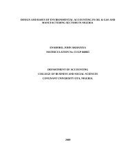
method. The outer frame of the single-phase<br />
capacitor start induction motor as shown in Figure<br />
5 indicates the positions <strong>for</strong> the electronic switch<br />
and the capacitor compartments.<br />
<strong>Switching</strong> circuit +<br />
Terminal-Box<br />
Compartment<br />
Figure 5: The Proposed Outer Frame<br />
Construction of the <strong>Single</strong>-phase <strong>Induction</strong> Motor.<br />
The electronic switching process will lower<br />
maintenance cost as the centrifugal mechanism is<br />
completely replaced. Smaller motors are also<br />
made possible as the space usually occupied by<br />
the mechanical switch will be no more. Hence, the<br />
smaller an induction motor is, the lower the cost of<br />
constructing it.<br />
REFERENCES<br />
1. Theraja, B.L. and A.K. Theraja. 2002. Electrical<br />
Technology. S. Chand and Company Ltd.: New<br />
Delhi, India.<br />
2. Werninck, E.H. 1978. Electric Motor Handbook.<br />
McGraw-Hill: New York, NY.<br />
3. Boylestad, R. and L. Nashelsky. 1993. Electronic<br />
Devices and <strong>Circuit</strong> Theory. Prentice-Hall: New<br />
Delhi, India.<br />
4. Rosenberg, R. 1985. Electric Motor Repairs. Holt-<br />
Saunders: New York, NY.<br />
ABOUT THE AUTHORS<br />
Mr. Ishioma A. Odigwe is a Lecturer and a<br />
Research Assistant with Covenant University, Ota<br />
in the Department of Electrical and In<strong>for</strong>mation<br />
Engineering. He holds a Bachelors and a<br />
Masters degree in Electrical Engineering. He is a<br />
Member of the IET (<strong>for</strong>merly IEE), Member of the<br />
IEEE, and Member of the Nigerian Society of<br />
Engineers (NSE). His research interests are in<br />
renewable energy sources, power system<br />
dynamics, protection and control.<br />
Starting capacitor<br />
compartment Mr. Antony U. Adoghe is a Lecturer and a<br />
Research Assistant with Covenant University,<br />
Ota in the Department of Electrical and<br />
In<strong>for</strong>mation Engineering. He holds a Bachelors<br />
and a Masters degree in Electrical Engineering.<br />
He is a Member of the IEEE, and Member of the<br />
Nigerian Society of Engineers (NSE). His<br />
research interests are in power system reliability,<br />
protection and control.<br />
Mr. Ayokunle A. Awelewa is a Lecturer and a<br />
Research Assistant with Covenant University,<br />
Ota in the Department of Electrical and<br />
In<strong>for</strong>mation Engineering. He holds a Bachelors<br />
and a Masters degree in Electrical Engineering.<br />
He is a Member of the IEEE, and Member of the<br />
Nigerian Society of Engineers (NSE). His<br />
research interests are in power system reliability,<br />
stability and control.<br />
Engr. Isaac A. Samuel is a Lecturer and a<br />
Research Assistant with Covenant University,<br />
Ota in the Department of Electrical and<br />
In<strong>for</strong>mation Engineering. He holds a Bachelors<br />
and a Masters degree in Electrical Engineering.<br />
He is a Member of the Nigerian Society of<br />
Engineers (NSE) and a registered engineer with<br />
the council <strong>for</strong> regulation of engineering in<br />
Nigeria (COREN). His research interests are in<br />
power system reliability, maintenance and<br />
operation.<br />
SUGGESTED CITATION<br />
Odigwe, I.A., A.U. Adoghe, A.A. Awelewa, and<br />
I.A. Samuel. 2008. “<strong>Auxiliary</strong> <strong>Winding</strong> <strong>Switching</strong><br />
<strong>Circuit</strong> <strong>for</strong> <strong>Single</strong>-<strong>Phase</strong> <strong>Induction</strong> <strong>Motors</strong>”.<br />
Pacific Journal of Science and Technology.<br />
9(2):324-327.<br />
Pacific Journal of Science and Technology<br />
The Pacific Journal of Science and Technology –327–<br />
http://www.akamaiuniversity.us/PJST.htm Volume 9. Number 2. November 2008 (Fall)