AN1 Series - Chief
AN1 Series - Chief
AN1 Series - Chief

You also want an ePaper? Increase the reach of your titles
YUMPU automatically turns print PDFs into web optimized ePapers that Google loves.
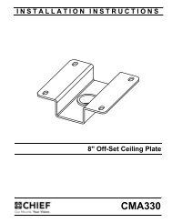
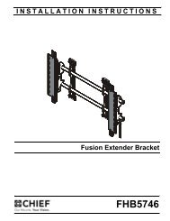
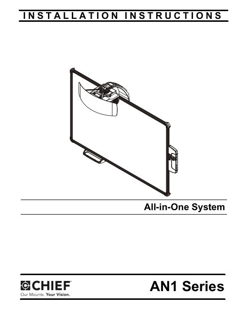
INSTALLATION INSTRUCTIONS<br />
All-in-One System<br />
Spanish Product Description<br />
German Product Description<br />
Portuguese Product Description<br />
Italian Product Description<br />
Dutch Product Description<br />
French Product Description<br />
<strong>AN1</strong> <strong>Series</strong>
<strong>AN1</strong> <strong>Series</strong> Installation Instructions<br />
DISCLAIMER<br />
Milestone AV Technologies and its affiliated corporations and<br />
subsidiaries (collectively "Milestone"), intend to make this<br />
manual accurate and complete. However, Milestone makes no<br />
claim that the information contained herein covers all details,<br />
conditions or variations, nor does it provide for every possible<br />
contingency in connection with the installation or use of this<br />
product. The information contained in this document is subject<br />
to change without notice or obligation of any kind. Milestone<br />
makes no representation of warranty, expressed or implied,<br />
regarding the information contained herein. Milestone assumes<br />
no responsibility for accuracy, completeness or sufficiency of<br />
the information contained in this document.<br />
<strong>Chief</strong>® is a registered trademark of Milestone AV Technologies.<br />
All rights reserved.<br />
2<br />
IMPORTANT SAFETY INSTRUCTIONS<br />
WARNING: A WARNING alerts you to the possibility of<br />
serious injury or death if you do not follow the instructions.<br />
CAUTION: A CAUTION alerts you to the possibility of<br />
damage or destruction of equipment if you do not follow the<br />
corresponding instructions.<br />
WARNING: Failure to read, thoroughly understand, and<br />
follow all instructions can result in serious personal injury,<br />
damage to equipment, or voiding of factory warranty! It is the<br />
installer’s responsibility to make sure all components are<br />
properly assembled and installed using the instructions<br />
provided.<br />
WARNING: Failure to provide adequate structural strength<br />
for this component can result in serious personal injury or<br />
damage to equipment! It is the installer’s responsibility to<br />
make sure the structure to which this component is attached<br />
can support five times the combined weight of all equipment.<br />
Reinforce the structure as required before installing the<br />
component. The wall to which the mount is being attached<br />
may have a maximum drywall thickness of 5/8" (1.6cm) for<br />
wood and steel stud walls, and NO drywall on concrete walls.<br />
WARNING: Use this mounting system only for its intended<br />
use as described in these instructions. Do not use<br />
attachments not recommended by the manufacturer.<br />
WARNING: Never operate this mounting system if it is<br />
damaged. Return the mounting system to a service center for<br />
examination and repair.<br />
WARNING: Do not use this product outdoors.<br />
IMPORTANT ! : The <strong>AN1</strong> <strong>Series</strong> mounts are designed to be<br />
used ONLY with the Epson BrightLink Pro 1410Wi projector.<br />
IMPORTANT ! : The <strong>AN1</strong> <strong>Series</strong> mounts are designed to be<br />
mounted to:<br />
an 8" concrete or 8"x8"x16" concrete block wall;<br />
a 2" x 4" wood studs (16" on center minimum) wall;<br />
a 2" x 4"-25ga minimum steel studs (16" on center<br />
minimum) wall.<br />
--SAVE THESE INSTRUCTIONS--
Installation Instructions <strong>AN1</strong> <strong>Series</strong><br />
DIMENSIONS<br />
DIMENSIONS: INCHES<br />
[MILLIMETERS]<br />
3
<strong>AN1</strong> <strong>Series</strong> Installation Instructions<br />
LEGEND<br />
4<br />
Tighten Fastener<br />
Apretar elemento de fijación<br />
Befestigungsteil festziehen<br />
Apertar fixador<br />
Serrare il fissaggio<br />
Bevestiging vastdraaien<br />
Serrez les fixations<br />
Loosen Fastener<br />
Aflojar elemento de fijación<br />
Befestigungsteil lösen<br />
Desapertar fixador<br />
Allentare il fissaggio<br />
Bevestiging losdraaien<br />
Desserrez les fixations<br />
Phillips Screwdriver<br />
Destornillador Phillips<br />
Kreuzschlitzschraubendreher<br />
Chave de fendas Phillips<br />
Cacciavite a stella<br />
Kruiskopschroevendraaier<br />
Tournevis à pointe cruciforme<br />
Open-Ended Wrench<br />
Llave de boca<br />
Gabelschlüssel<br />
Chave de bocas<br />
Chiave a punte aperte<br />
Steeksleutel<br />
Clé à fourche<br />
By Hand<br />
A mano<br />
Von Hand<br />
Com a mão<br />
A mano<br />
Met de hand<br />
À la main<br />
Hex-Head Wrench<br />
Llave de cabeza hexagonal<br />
Sechskantschlüssel<br />
Chave de cabeça sextavada<br />
Chiave esagonale<br />
Zeskantsleutel<br />
Clé à tête hexagonale<br />
Pencil Mark<br />
Marcar con lápiz<br />
Stiftmarkierung<br />
Marcar com lápis<br />
Segno a matita<br />
Potloodmerkteken<br />
Marquage au crayon<br />
Drill Hole<br />
Perforar<br />
Bohrloch<br />
Fazer furo<br />
Praticare un foro<br />
Gat boren<br />
Percez un trou<br />
Adjust<br />
Ajustar<br />
Einstellen<br />
Ajustar<br />
Regolare<br />
Afstellen<br />
Ajuster<br />
Remove<br />
Quitar<br />
Entfernen<br />
Remover<br />
Rimuovere<br />
Verwijderen<br />
Retirez<br />
Optional<br />
Opcional<br />
Optional<br />
Opcional<br />
Opzionale<br />
Optie<br />
En option<br />
Security Wrench<br />
Llave de seguridad<br />
Sicherheitsschlüssel<br />
Chave de segurança<br />
Chiave di sicurezza<br />
Veiligheidssleutel<br />
Clé de sécurité
Installation Instructions <strong>AN1</strong> <strong>Series</strong><br />
TOOLS REQUIRED FOR INSTALLATION<br />
PARTS<br />
1/8" (wood) #2<br />
7/16"<br />
1/2" (drywall)<br />
8mm (concrete)<br />
6mm (concrete - AF6 toggler)<br />
Q (1)<br />
[Screen assembly]<br />
Install<br />
Hardware<br />
Kit<br />
A (4)<br />
1/4 x 2-1/2"<br />
K (8)<br />
#8 x 1/2"<br />
B (4)<br />
Hilti Hud-L #8 x 60<br />
F (8)<br />
[4" cable tie]<br />
L (6)<br />
#8-9 x 1-1/2"<br />
R (1)<br />
[Wall bracket]<br />
U (1)<br />
[Boom projector<br />
mount]<br />
X (1)<br />
[Left valence bracket] Y (1)<br />
[Right valence bracket]<br />
Z (1)<br />
[RF Cable]<br />
G (4)<br />
10-24 x 3/8"<br />
M (6)<br />
Toggler AF6<br />
C (4)<br />
1/4-20 x 1-3/4"<br />
S (1)<br />
[Projector interface]<br />
D (4)<br />
1/4"<br />
E (4)<br />
1/4-20<br />
[Toggler anchor kit]<br />
H (10)<br />
10-24 x 3/8"<br />
N (2)<br />
#4-24 x 1/4"<br />
AA (1)<br />
[Valence]<br />
V (1)<br />
[Marker set]<br />
J (4)<br />
M4 x 10mm<br />
P (6)<br />
[Screen<br />
bracket]<br />
T (1)<br />
[Control panel<br />
assembly]<br />
W (1)<br />
[Marker tray]<br />
5
<strong>AN1</strong> <strong>Series</strong> Installation Instructions<br />
INSTALLATION<br />
Determining Location<br />
6<br />
1<br />
HEIGHT FROM FLOOR<br />
STUDS<br />
1. Determine desired height of screen (measured from floor).<br />
(See Figure 1)<br />
2. Determine desired center of screen. (See Figure 1)<br />
3. Measure 6.5 inches up from desired height (top) of screen<br />
and 2.75 inches to the right of center of screen and mark<br />
location. (See Figure 1)<br />
4. Determine location of studs behind drywall.<br />
5. Drill one pilot hole (see Table 1 for size) at location marked<br />
in Step 3 (See Figure 1) and follow fastener information<br />
(appropriate for wall type) located in Table 1.<br />
IMPORTANT ! : See Fastener Installation Methods at<br />
end of Installation Instructions for details on installing<br />
product into various wall types.<br />
Figure 1<br />
CENTER OF SCREEN<br />
73.00”<br />
2<br />
2.75”<br />
WALL TYPE PILOT<br />
HOLE<br />
Drywall only-<br />
(boom attach<br />
only) /<br />
Steel studs<br />
3 5<br />
FLOOR<br />
Table 1: Fastener Information<br />
6.50” 2<br />
46.00”<br />
FASTENERS (see<br />
PARTS drawing)<br />
1/2" 1/4-20 Toggler anchor kit (C,<br />
D, E)<br />
- 1/4-20 x 1-3/4" Phillips<br />
screw (C)<br />
- 1/4" washer (D)<br />
- 1/4-20 Snap toggler (E)<br />
Wood stud 1/8" 1/4 x 2-1/2" hex head lag (A)<br />
Concrete 8mm x 80mm<br />
(Only for<br />
installing<br />
screen bracket<br />
into concrete)<br />
6mm x 45mm<br />
1/4 x 2-1/2" hex head lag (A)<br />
Hilti Hud-L #8x60 anchor (B)<br />
#8-9x1-1/2" Phillips screw(L)<br />
Toggler AF6 (M)
Installation Instructions <strong>AN1</strong> <strong>Series</strong><br />
Installing Wall Bracket / Boom Projector Mount<br />
1. Install one fastener (See Table 1) into previously drilled<br />
hole, leaving 1/2" of fastener extending from wall. (See<br />
Figure 2)<br />
Notch indicates<br />
center of screen<br />
Figure 2<br />
2. Hang wall bracket (R) onto fastener.<br />
NOTE: Notch in wall bracket (R) indicates center of screen.<br />
(See Figure 2)<br />
3. Tighten fastener against wall bracket.<br />
4. Lower boom projector mount (U) onto wall bracket (R)<br />
matching two fastener holes in upper arm with holes in<br />
upper wall bracket. (See Figure 3)<br />
5. Align four fastener holes along bottom of boom projector<br />
mount with four holes in wall bracket. (See Figure 3)<br />
(R)<br />
1<br />
3<br />
Figure 3<br />
x 1<br />
(U)<br />
4<br />
5<br />
(R)<br />
6. Install and tighten two 10-24 x 3/8" Phillips cap head screws<br />
(H) through upper arm of boom projector mount (U) into<br />
vertical portion of wall bracket (R). (See Figure 4)<br />
7. Install and tighten four 10-24 x 3/8" Phillips flat head screws<br />
(G) through wall bracket (R) into boom projector arm (U).<br />
(See Figure 4)<br />
8. Determine location of studs behind drywall, and mark a<br />
minimum of two locations for wall bracket attachment over<br />
studs.<br />
NOTE: For concrete walls, mark at least two locations for<br />
attachment a minimum of 16" apart AND within slots on<br />
wall bracket (R).<br />
9. Drill one pilot hole (see Table 1 for size) at each location<br />
marked in Step 8 (See Figure 4) and follow fastener<br />
information (appropriate for wall type) located in Table 1.<br />
NOTE: Proceed to Fastener Installation Methods section at<br />
end of Installation Instructions.<br />
10. Fasten wall bracket assembly to wall using fasteners<br />
appropriate to wall type (See Table 1). (See Figure 4)<br />
(U)<br />
8<br />
7<br />
9 10<br />
(G) x 4<br />
Figure 4<br />
6<br />
x 2 (minimum)<br />
(H) x 2<br />
(R)<br />
7
<strong>AN1</strong> <strong>Series</strong> Installation Instructions<br />
Attaching Screen<br />
1. Hang screen assembly (Q) onto wall bracket (R) using pre-installed bracket on back of screen assembly. (See Figure 5)<br />
2. Center screen assembly on wall bracket, matching pieces of tape on top of screen with edges of boom mount on wall bracket.<br />
NOTE: Notch in wall bracket (R) indicates center of screen. (See Figure 2)<br />
8<br />
Pre-installed<br />
bracket<br />
Tape<br />
locations<br />
3. Using screen brackets (P) as a template, locate studs, slide<br />
bracket up under screen, and trace line under brackets at<br />
locations on studs or on concrete wall. (See Figure 6)<br />
NOTE: Use 3 screen brackets (minimum of 2 brackets) along<br />
bottom of screen, and locate brackets as close to outer<br />
corners as possible. Remaining brackets may be used<br />
along sides of screen, as desired.<br />
4 4<br />
3 3<br />
3<br />
Mark location by<br />
tracing line under<br />
bracket<br />
(Wood or steel<br />
stud installation<br />
shown as example)<br />
(P)<br />
Figure 6<br />
1<br />
Lower frame<br />
of screen<br />
Figure 5<br />
1<br />
(Q)<br />
(R)<br />
(View shown from behind<br />
wall to which wall bracket<br />
is attached)<br />
4. Lift and remove screen from wall bracket.<br />
5. Install screen brackets (P) using:<br />
Wood/steel studs: one #8-9 x 1-1/2" wood screw (L)<br />
into top of each bracket slot and slightly lower than<br />
marked location. (See Figure 6)<br />
Concrete wall: one #8-9 x 1-1/2" wood screw (L) into<br />
top of each bracket slot and slightly lower than<br />
marked location, and into installed AF6 toggler. (See<br />
Figure 6)<br />
6. Replace screen onto wall bracket.<br />
7. Slide screen brackets (P) up on wood screw and fasten to<br />
screen frame using one #8 x 1/2" self-drilling screw (K) per<br />
screen bracket (P). (See Figure 7)<br />
7<br />
Bottom of<br />
screen<br />
(K)<br />
Figure 7<br />
(P)
Installation Instructions <strong>AN1</strong> <strong>Series</strong><br />
Installing Projector<br />
1. Attach projector interface (S) to projector using four<br />
M4 x 10mm Phillips cap head screws (J). (See Figure 8)<br />
Figure 8<br />
2. Lift projector with attached interface (S) and slide buttons on<br />
interface into slots on boom projector mount (U). (See<br />
Figure 9)<br />
Slot<br />
Latch<br />
Buttons<br />
LOCKED 3<br />
Figure 9<br />
3. Slide latch to LOCKED position to lock projector in place.<br />
(See Figure 9)<br />
2<br />
1<br />
Slot<br />
(J) x 4<br />
(U)<br />
(S)<br />
(S)<br />
Installing Control Housing<br />
1. Open door on control panel assembly (T).<br />
2. Insert edges of control panel assembly (T) into groove in<br />
screen frame, with tab placed behind screen. (See Figure 10)<br />
3. Slide control panel assembly up along side of screen<br />
assembly to the desired height. (See Figure 10)<br />
Screen<br />
4<br />
Attach to wall<br />
through this slot<br />
Figure 10<br />
4. Determine attachment location on wall. (See Figure 10)<br />
5. Mark attachment hole through slot in control panel<br />
assembly (T). (See Figure 10)<br />
6. Slide control panel assembly up or down, away from<br />
marked hole.<br />
7. Drill one pilot hole (see Table 1 for size) at location marked<br />
in Step 5 (See Figure 10) and follow fastener information<br />
(appropriate for wall type) located in Table 1.<br />
8. Proceed to Fastener Installation Methods section at end<br />
of Installation Instructions.<br />
3<br />
5<br />
7<br />
(T)<br />
9
<strong>AN1</strong> <strong>Series</strong> Installation Instructions<br />
Installing Control Pad<br />
1. Remove top cover from control pad. (See Figure 11)<br />
2. Open lower cover on control pad. (See Figure 11)<br />
3. Insert control pad into control housing (T) by sliding it up<br />
under tabs inside housing. (See Figure 11)<br />
10<br />
1<br />
2<br />
Lower cover<br />
Control<br />
pad<br />
Figure 11<br />
Top cover<br />
Tabs<br />
4. Align holes in control pad with bosses in control housing<br />
and push control pad into place. (See Figure 12)<br />
5. Secure control pad into place using two #4-24 x 1/4" Phillips<br />
pan head screws (N). Do NOT overtighten. (See Figure 12)<br />
6. Attach all cables, including RF cable (Z), to control pad<br />
following instructions included with projector/control pad.<br />
IMPORTANT ! : Connect cables BEFORE replacing control<br />
pad cover.<br />
7. Use cable ties (F), as necessary, to secure the cables within<br />
control panel. (See Figure 12)<br />
8. Replace top cover onto control pad. (See Figure 12)<br />
3<br />
(T)<br />
6<br />
4 Bosses<br />
25<br />
5<br />
Connect cables<br />
BEFORE replacing<br />
control pad cover.<br />
8<br />
(N) x 2<br />
Figure 12<br />
9. OPTIONAL: The tab in the control panel assembly door<br />
may be removed to allow attachment to the USB port. (See<br />
Figure 12)<br />
7<br />
Tab<br />
USB port<br />
Cable<br />
tie<br />
anchors<br />
9
Installation Instructions <strong>AN1</strong> <strong>Series</strong><br />
Projector Adjustments<br />
Yaw Adjustment<br />
1. Loosen yaw adjustment locking screw using a #2 Phillips<br />
screwdriver. (See Figure 13)<br />
2. Turn yaw micro-adjustment screw right or left using a #2<br />
Phillips screwdriver until image is properly aligned on target.<br />
3. Tighten yaw adjustment locking screw using a #2 Phillips<br />
screwdriver. (See Figure 13)<br />
Pitch Adjustment<br />
Figure 13<br />
1. Loosen pitch adjustment locking screw using a #2 Phillips<br />
screwdriver. (See Figure 14)<br />
2. Turn pitch micro-adjustment screw right or left using a #2<br />
Phillips screwdriver until image is properly aligned on target.<br />
3. Tighten pitch adjustment locking screw using a #2 Phillips<br />
screwdriver.<br />
2<br />
1 3<br />
2<br />
Roll Adjustment<br />
Figure 14<br />
1. Loosen roll adjustment locking screw using a #2 Phillips<br />
screwdriver. (See Figure 15)<br />
2. Turn roll micro-adjustment screw right or left using a #2<br />
Phillips screwdriver until image is properly aligned on target.<br />
3. Tighten roll adjustment locking screw using a #2 Phillips<br />
screwdriver.<br />
1 3<br />
2<br />
Figure 15<br />
1 3<br />
11
<strong>AN1</strong> <strong>Series</strong> Installation Instructions<br />
Micro Adjustment<br />
1. If required, turn the micro adjust fastener clockwise to<br />
extend projector further from wall. (See Figure 16)<br />
2. If required, turn the micro adjust fastener<br />
counterclockwise to retract projector closer to wall.<br />
12<br />
1 Extend<br />
2<br />
Attaching Marker Tray<br />
Figure 16<br />
1. Attach marker tray (W) at any point along bottom of screen<br />
frame using two #8 x 1/2" self-drilling screws (K). (See<br />
Figure 17)<br />
1<br />
Retract<br />
(W)<br />
(K) x 2<br />
Attaching Valence<br />
Figure 17<br />
1. Align right valence bracket (Y) along outside of right brace<br />
on back of valence (AA), and fasten with two 10-24 x 3/8"<br />
Phillips pan head machine screws (H). (See Figure 18)<br />
2. Align left valence bracket (X) along outside of left brace on<br />
back of valence (AA), and fasten with two 10-24 x 3/8"<br />
Phillips pan head machine screws (H). (See Figure 18)<br />
(X)<br />
Left brace<br />
1<br />
Figure 18<br />
3. Slide the valence (AA) with attached brackets into the boom<br />
mount (U), sliding brackets under tabs in boom. (See<br />
Figure 19)<br />
4. Adjust distance as required.<br />
2<br />
5. Fasten through bracket slots into boom mount using four<br />
10-24 x 3/8" Phillips pan head machine screws (H). (See<br />
Figure 19)<br />
(AA)<br />
2<br />
Tabs<br />
3<br />
(H) x 2<br />
(AA)<br />
Right brace<br />
Figure 19<br />
5<br />
1<br />
(Y)<br />
Bracket<br />
placed on<br />
outside edge<br />
of brace<br />
(H) x 4
Installation Instructions <strong>AN1</strong> <strong>Series</strong><br />
FASTENER INSTALLATION METHODS<br />
NOTE: Refer to Table 1 for appropriate hardware and pilot hole<br />
sizes for various wall types.<br />
Steel Stud / Drywall<br />
1. Hold metal channel on anchor (E) flat alongside plastic<br />
straps and slide channel through hole. (See Figure 20)<br />
Drywall<br />
Plastic straps<br />
(E)<br />
Figure 20<br />
2. Holding plastic straps on anchor (E), pull anchor away from<br />
wall until channel rests flush behind wall making sure anchor<br />
channel is positioned vertically on drywall, or steel stud (if<br />
present). (See Figure 21)<br />
3. Slide plastic cap on anchor (E) towards wall until flange of<br />
cap is flush with wall. (See Figure 21)<br />
Plastic cap<br />
(side view)<br />
Steel stud<br />
(if present)<br />
Drywall<br />
3<br />
(E)<br />
Anchor metal channel<br />
Figure 21<br />
4. Snap off plastic straps on anchor at wall by pushing side to<br />
side, snapping off straps level with flange of plastic cap.<br />
(See Figure 22)<br />
1<br />
2<br />
4<br />
Plastic straps<br />
(side view)<br />
Figure 22<br />
5. Line up anchor with attachment point.<br />
6. Insert 1/4-20 x 1-3/4" Phillips pan head screw (C) through<br />
1/4" washer (D), corresponding mounting hole in product<br />
and into anchor (E), and tighten until flush against product.<br />
DO NOT overtighten! (See Figure 23)<br />
6<br />
Wood Stud<br />
(D) x 4<br />
Steel stud<br />
(if present)<br />
Drywall<br />
Plastic cap<br />
Anchor metal channel<br />
Steel stud<br />
(if present)<br />
Drywall<br />
(C) x 4<br />
Anchor metal channel<br />
(side view)<br />
Figure 23<br />
NOTE: Refer to Table 1 for appropriate hardware and pilot hole<br />
sizes for various wall types.<br />
1. Use one 1/4 x 2-1/2" lag bolt through product and into pilot<br />
hole. (See Figure 24)<br />
2. Repeat for remaining pilot hole.<br />
1<br />
2<br />
Product<br />
(A) x 2<br />
Figure 24<br />
13
<strong>AN1</strong> <strong>Series</strong> Installation Instructions<br />
Concrete<br />
NOTE: Refer to Table 1 for appropriate hardware and pilot hole<br />
sizes for various wall types.<br />
1. Install an anchor (B) into each pilot hole using a hammer,<br />
making sure that the anchor is flush with the wall.<br />
2. Use one 1/4 x 2-1/2" lag bolt (A) through product into each<br />
anchor in wall.<br />
14<br />
2<br />
(A)<br />
Figure 25<br />
1<br />
(B)
Installation Instructions <strong>AN1</strong> <strong>Series</strong><br />
15
<strong>AN1</strong> <strong>Series</strong> Installation Instructions<br />
<strong>Chief</strong> Manufacturing, a products division<br />
of Milestone AV Technologies<br />
8800-002354 Rev01<br />
2013 Milestone AV Technologies, a<br />
Duchossois Group Company<br />
www.chiefmfg.com<br />
05/13<br />
USA/International A 6436 City West Parkway, Eden Prairie, MN 55344<br />
P 800.582.6480 / 952.225.6000<br />
F 877.894.6918 / 952.894.6918<br />
Europe A Franklinstraat 14, 6003 DK Weert, Netherlands<br />
P +31 (0) 495 580 852<br />
F +31 (0) 495 580 845<br />
Asia Pacific A Office No. 1 on 12/F, Shatin Galleria<br />
18-24 Shan Mei Street<br />
Fotan, Shatin, Hong Kong<br />
P 852 2145 4099<br />
F 852 2145 4477