EQUINOX LV - Salicru, SA
EQUINOX LV - Salicru, SA
EQUINOX LV - Salicru, SA

Create successful ePaper yourself
Turn your PDF publications into a flip-book with our unique Google optimized e-Paper software.
UNINTERRUPTIBLE POWER SUPPLY (UPS) + VOLTAGE STABILIZERS AND POWER LINE CONDITIONERS + SWITCH MODE POWER SUPPLY + INDUSTRIAL POWER SUPPLY + LIGHTING FLOW DIMMER STABILIZERS + STATIC INVERTERS<br />
USEr’S MaNUaL<br />
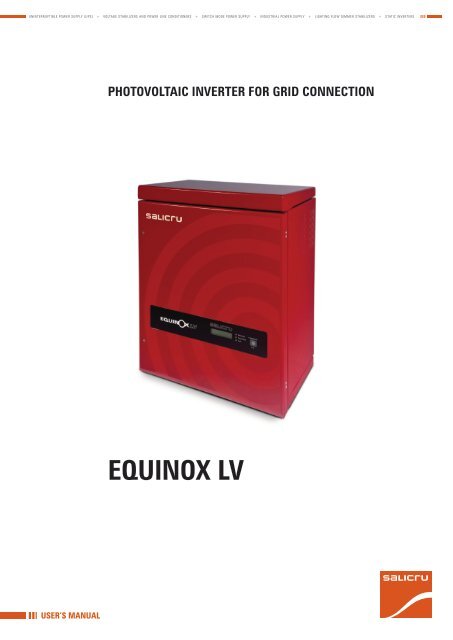
phOtOVOLtaIc INVErtEr fOr grId cONNEctION<br />
<strong>EQUINOX</strong> <strong>LV</strong>
gENEraL INdEX<br />
1. INtrOdUctION.<br />
1.1. GRATEFULNESS LETTER.<br />
1.2. USING THIS MANUAL.<br />
1.2.1. Conventions and used symbols.<br />
1.2.2. For more information and/or help.<br />
2. QUaLIty aNd StaNdard gUaraNtEE.<br />
2.1. MANAGEMENT DECLARATION.<br />
2.2. STANDARD.<br />
2.3. ENVIRONMENT.<br />
3. prESENtatION.<br />
3.1. VIEWS.<br />
3.1.1. Wall mounting case.<br />
3.1.2. Control panel.<br />
3.2. DEFINITION AND STRUCTURE.<br />
3.2.1. Nomenclature.<br />
3.3. DESCRIPTION OF THE SYSTEM.<br />
3.3.1. Main quality performances.<br />
4. INStaLLatION.<br />
4.1. IMPORTANT <strong>SA</strong>FETY INSTRUCTIONS.<br />
4.1.1. To keep in mind.<br />
4.2. RECEPTION OF THE EqUIPMENT.<br />
4.2.1. Unpacking and contents checking.<br />
4.2.2. Location.<br />
4.2.3. Physical installation.<br />
4.3. CONNECTION.<br />
4.3.1. Of DC input.<br />
4.3.2. Of AC output.<br />
4.4. UNINSTALLATION.<br />
4.5. INSTALLATION AND COMMUNICATION PROTOCOL FOR LAN.<br />
5. OpEratINg.<br />
5.1. START UP AND SHUTDOWN.<br />
5.1.1. First start up.<br />
5.2. CONTROL PANEL.<br />
5.2.1. Modes of LCD panel and their functions.<br />
5.2.2. Shutdown procedure.<br />
SaLIcrU<br />
6. MaINtENaNcE, warraNty aNd SErVIcE.<br />
6.1. MAINTENANCE BASIC GUIDE.<br />
6.2. TROUBLESHOOTING.<br />
6.3. WARRANTY CONDITIONS.<br />
6.3.1. Covered product.<br />
6.3.2. Warranty terms.<br />
6.3.3. Out of scope of supply.<br />
6.4. DESCRIPTION OF AVAILABLE MAINTENANCE CONTRACTS AND<br />
SERVICES.<br />
6.5. TECHNICAL SERVICE NETWORk.<br />
7. aNNEXES.<br />
7.1. TECHNICAL FEATURES.<br />
7.2. TYPICAL INSTALLATION OF EqUINOX - THIN-FILM MODULES IN<br />
PARALLEL CONFIGURATION.<br />
3
4<br />
1. INtrOdUctION.<br />
1.1. gratEfULNESS LEttEr.<br />
We would like to thank you in advance for the trust you have placed<br />
in us by purchasing this product. Read this instruction manual carefully<br />
before starting up the equipment and keep it for any possible<br />
future consult that can arise.<br />
We remain at you entire disposal for any further information or any<br />
query you should wish to make.<br />
Yours sincerely.<br />
SaLIcrU<br />
The equipment here described can cause important physical<br />
damages due to wrong handling. This is why, the installation,<br />
maintenance and/or fixing of the here described equipment<br />
must be done by our staff or specifically authorised.<br />
According to our policy of constant evolution, we reserve<br />
the right to modify the specifications in part or in whole<br />
without forewarning.<br />
All reproduction or third party concession of this manual is<br />
prohibited without the previous written authorization of our<br />
firm.<br />
1.2. USINg thIS MaNUaL.<br />
The purpose of this manual is to give explanations and procedures for<br />
the installation and operating of the equipment. This manual has to<br />
be read carefully before installing and operating it. keep this manual for<br />
future consults.<br />
1.2.1. conventions and used symbols.<br />
«warning» symbol. Carefully read the indicated paragraph<br />
and take the stated prevention measures.<br />
«danger of electrical discharge» symbol. Pay special<br />
attention to it, both in the indication on the equipment<br />
and in the paragraph referred to this user’s manual.<br />
i<br />
i<br />
«Main protective earthing terminal» symbol. Connect<br />
the earth cable coming from the installation to this terminal.<br />
«Notes of information» symbol. Additional topics that<br />
complement the basic procedures.<br />
preservation of the environment: The presence of this<br />
symbol in the product or in their associated documentation<br />
states that, when its useful life is expired, it will not be disposed<br />
together with the domestic residuals. In order to avoid possible<br />
damages to the environment, separate this product from other residuals<br />
and recycle it suitably. The users can contact with their provider<br />
or with the pertinent local authorities to be informed on how<br />
and where they can take the product to be recycled and/or disposed<br />
correctly.<br />
1.2.2. for more information and/or help.<br />
For more information and/or help of the version of your specific unit,<br />
request it to our Service and Technical Support (S.t.S.).<br />
USEr MaNUaL
2. QUaLIty aNd StaNdard gUaraNtEE.<br />
2.1. MaNagEMENt dEcLaratION.<br />
Our target is the client’s satisfaction, therefore this Management<br />
has decided to establish a quality and Environmental policy, by<br />
means of installation a quality and Environmental Management<br />
System that becomes us capable to comply the requirements demanded<br />
by the standard ISO 9001:2000 and ISO 14001:2004<br />
and by our Clients and concerned parts too.<br />
Likewise, the enterprise Management is committed with the development<br />
and improvement of the quality and Environmental Management<br />
System, through:<br />
• The communication to all the company about the importance<br />
of satisfaction both in the client’s requirements and in the legal<br />
and regulations.<br />
•<br />
The quality and Environmental Policy diffusion and the fixation<br />
of the quality and Environment targets.<br />
• To carry out revisions by the Management.<br />
• To provide the needed resources.<br />
Management agent.<br />
The Management has designated as management agent the person<br />
in charge about the quality and Environment department, who with<br />
independence of other responsibilities, has the responsibility and<br />
authority to assure that the processes of the quality and environmental<br />
management system are established and maintained; to<br />
inform to the Management about the operating of the quality and<br />
environmental management system, including the necessities for<br />
the improvement; and to promote the knowledge of the client’s requirements<br />
and environmental requirements at all the levels of the<br />
organization.<br />
In the next PROCESS MAP is represented the interaction among all<br />
the processes of the quality and Environmental System:<br />
cLIENtS<br />
fig. 9.<br />
cONtINUOUS IMprOVEMENt prOcESS / MaNagEMENt<br />
rEVIEw<br />
QUaLIty<br />
MaNagEMENt<br />
prOcESS<br />
r & d prOcESS<br />
cOMMErcIaL<br />
prOcESS<br />
INtErNaL LOgIStIc prOcESS<br />
SaLIcrU<br />
MaINtENaNcE prOcESS<br />
traININg prOcESS<br />
ENVIrONMENtaL<br />
MaNagEMENt<br />
prOcESS<br />
tEchNIcaL OffIcE<br />
prOcESS<br />
MaNUfactUrINg<br />
prOcESS<br />
cLIENtS:<br />
- prOdUct<br />
- SErVIcE<br />
Process map of quality and Environment system.<br />
2.2. StaNdard.<br />
The <strong>EQUINOX</strong> <strong>LV</strong> product is designed, manufactured and commercialized<br />
in accordance with the standard EN ISO 9001 of quality<br />
Assurance. The marking shows the conformity to the EEC Directive<br />
(quoted between brackets) by means of the application of the<br />
following standards:<br />
• 2006/95/Ec of Low Voltage Safety.<br />
• 2004/108/Ec of Electromagnetic Compatibility (EMC).<br />
In accordance with the harmonized standards. Reference regulations:<br />
• EMc:<br />
DIN EN 61000-6-3 (VDE0839-6-3, EMV-interference<br />
emission) (class B) y DIN EN 61000-6-2 (VDE08039-6-2. EMVinterference<br />
immunity).<br />
• grid perturbations:<br />
DIN EN 61000-3-2 / DIN EN 61000-3-3<br />
• grid monitoring:<br />
Independent devices of disconnection (MSD,<br />
Grid monitoring with switching devices) in accordance with<br />
VDEW; EN DIN VDE 0126-1-1 (2006.02).<br />
• Low voltage:<br />
DIN EN 50178 (4.98) (VDE 0160) (IEC62103) and<br />
DIN EN 60146 part 1-1 (3.94) (VDE 0558 part 11).<br />
• dc switching:<br />
VDE0100-7-712, requirements of the system<br />
(not standard).<br />
2.3. ENVIrONMENt.<br />
This product has been designed to respect the environment and has<br />
been manufactured in accordance with the standard ISO 14001.<br />
recycling the device at the end of its useful life:<br />
Our company commits to use the services of authorised societies<br />
and according to the regulations, in order to treat the recovered<br />
product at the end of its useful life (contact your distributor).<br />
packaging: To recycle the packing, follow the legal regulations in<br />
force.<br />
5
6<br />
3. prESENtatION.<br />
This manual contents the instructions to install, start up, maintenance<br />
and troubleshooting of <strong>EQUINOX</strong> <strong>LV</strong> photovoltaic inverters<br />
for grid connection.<br />
3.1. VIEwS.<br />
3.1.1. wall mounting case.<br />
fig. 1.<br />
fig. 2.<br />
Details of wall mounting case opened and closed<br />
Detail of removing power electronic module and ter-<br />
minal block<br />
3.1.2. control panel.<br />
The following figure shows the appereance of control panel of these<br />
equipments, which is based on on/off button and LCD panel of 2<br />
rows and 16 characteres.<br />
fig. 3.<br />
Control panel view of the system<br />
Generating Wake/Scroll<br />
Earth Leakage<br />
Fault<br />
3.2. dEfINItION aNd StrUctUrE.<br />
3.2.1. Nomenclature.<br />
3.3. dEScrIptION Of thE SyStEM.<br />
Photovoltaic inverters <strong>EQUINOX</strong> <strong>LV</strong> series are the only ones in the<br />
market with Step pulse technology of low voltage, offering several<br />
unique advantages like the massive parallel connection of thin-film<br />
modules paraLEX without serial connections, easier design of<br />
installations, low influence of shadow areas or shorter payback period.<br />
fig. 4.<br />
“Step pulse” technology.<br />
3.3.1. Main quality performances.<br />
• Patented technology of Step pulse.<br />
• Low voltage operating of photovoltaic field.<br />
• Compatible with any type of photovoltaic panel (single-crystal<br />
+ thin-film).<br />
• Optimized for thin-film panels.<br />
• No efficiency derate when overheating.<br />
• Increasing the production till 10% when doing the connection of<br />
massive equipments in parallel to the photovoltaic field.<br />
• Efficiency > 95%<br />
• Power factor > 0,99<br />
• Integrated galvanic isolation.<br />
• Modular design to make easier its installation and maintenance.<br />
• Communication ports RS485 and Ethernet.<br />
• Integrated datalogger for historical of production and events.<br />
• LCD screen to follow up the energy generation.<br />
• Electronics completely sealed, ready for outdoor applications.<br />
• LAN communication.<br />
• Acquistion software for remote data.<br />
• Up to 120 days of data storage.<br />
USEr MaNUaL
4. INStaLLatION.<br />
4.1. IMpOrtaNt SafEty INStrUctIONS.<br />
KEEp thIS INStrUctIONS<br />
This manual has important instructions for <strong>EQUINOX</strong> <strong>LV</strong> photovoltaic<br />
inverter for grid connection, which has to be followed during<br />
its installation and maintenance.<br />
daNgEr ! haZardOUS VOLtagES<br />
this inverter has hazardous voltages. It can only be installed by<br />
qualified personnel that has been read this manual and it is familiar<br />
with its handling.<br />
1.<br />
2.<br />
3.<br />
4.<br />
5.<br />
6.<br />
7.<br />
Connect the output of the inverter to 230 VAC, 50 Hz, grid<br />
only, and according to the electrical diagrams showed in this<br />
manual.<br />
Connect the input of the inverter to a photovoltaic matrix set<br />
to work inside the voltage and current limits stated in this<br />
manual.<br />
Be sure that the earth connection is done in accordance with<br />
the local regulations.<br />
Be sure the cooling is enough to cool it down suitably.<br />
Never operate the system in a different way as the stated in<br />
this manual.<br />
The equipment can only be maintained by qualified personnel.<br />
Once the installation has been finished, check that all covers<br />
are well fixed.<br />
4.1.1. to keep in mind.<br />
Before proceeding with the installation, read all the instructions and<br />
warnings of this manual in order to be get used with the installation<br />
procedure.<br />
any installation work has to be done in accordance<br />
with the local regulations.<br />
Isolate the inverter of any power supply before installing<br />
it by means of switches, circuit breakers,<br />
connectors or sun protectors for panels. Insulation failures<br />
in ac or dc power supplies can cause serious injuries or<br />
even the death.<br />
SaLIcrU<br />
4.2. rEcEptION Of thE EQUIpMENt.<br />
4.2.1. Unpacking and contents checking.<br />
Once received, the inverter has to be visually inspected in order to<br />
detect possible damages made by transport. In case they would be,<br />
contact with your local distributor. Check that packaging contents<br />
the following elements:<br />
•<br />
•<br />
•<br />
•<br />
1 Electronic module.<br />
1 Transformer module.<br />
1 Wall mounting support.<br />
1 kit for wall mounting assembling.<br />
4.2.2. Location.<br />
keep in mind the following considerations when choosing the location<br />
of the inverter:<br />
1. Inverter enclosure is ready to be installed outdoors in noncorrosive<br />
environments. Avoid direct sunlight.<br />
2. It is important to locate the inverter in appropiate height to<br />
make easier: its connection, LCD panel reading and future inspection<br />
and/or maintenance tasks.<br />
4.2.3. physical installation.<br />
The following procedure describes the installation of the inverter as<br />
part of a photovoltaic system.<br />
weight of transformer module is 64 Kg. handle it<br />
with care.<br />
Total weight of the inverter is 76 kg. Support has to be fixed to a<br />
structure able to support its weight. There are some particular requirements<br />
depending on the type of wall (steel, wood, cement).<br />
Step by step installation procedure (see fig.1):<br />
1.<br />
2.<br />
3.<br />
4.<br />
Put the support against the wall, by considering the installation<br />
height in order to have the wiring access at usual working<br />
height. Fix the support to the wall by using bolts with metric<br />
M8.<br />
Unpack the transformer module and hang it up on the support.<br />
Fix the transformer module to the support by using the 2 supplied<br />
screws.<br />
Unpack the electronic module and slide it over the lower<br />
guides of transformer module. Fix it to the left and right sides<br />
of transformer module by using the 4 supplied screws. Connect<br />
the earth cable from the electronic module to the transformer<br />
module.<br />
7
5.<br />
6.<br />
8<br />
Connect the left and right power cables from transformer to<br />
the studs in the rear side of electronic module. Connectors<br />
have a tactile mechanical locking. Connect the AC power cable<br />
to the rear side (bottom left) of electronic module.<br />
Note: avoid that cables touch the transformers.<br />
Connect the AC cables from grid to AC connector located at<br />
bottom-right side of transformer module.<br />
Put the left and right covers of transformer module. Connect<br />
the earth cables and fix the covers to transformer module by<br />
using the 2 supplied screws (it is only shown the left side - repeat<br />
the process for left side).<br />
fig. 5.<br />
Process of physical installation.<br />
4.3. cONNEctION.<br />
Wiring methods must be in accordance with local regulations.<br />
Appendix A includes a detailed electrical diagram for a typical<br />
EqUINOX <strong>LV</strong> system.<br />
photovoltaic modules (pV) have to be disconnected<br />
from wires that link the panel with the inverter before<br />
the installation. risk of electrocution.<br />
4.3.1. Of dc input.<br />
The following procedure describes the steps to connect the inverter<br />
to the photovoltaic panels.<br />
attention: a wrong connection can both damage<br />
the equipment and make injuries to the personnel.<br />
do no exceed the stated maximum dc voltage.<br />
1.<br />
2.<br />
3.<br />
4.<br />
5.<br />
6.<br />
7.<br />
Check that power supply cables from photovoltaic panels are<br />
disconnected or not alive.<br />
do not disconnect the cables from photovoltaic<br />
panels, risk of electrocution exists.<br />
Address the DC cables from panels to DC input cable glands of<br />
combinator module.<br />
Connect the negative cable to “PV Array Negative” terminal<br />
strip.<br />
Connect the positive cable to “PV Array Positive” terminal<br />
strip.<br />
Connect the photovoltaic panels to the wires of combinator<br />
module.<br />
Check the open circuit voltage of each circuit (positive cable<br />
of each circuit has to be isolated from DC bus) with a digital<br />
voltmeter. Check the voltage between each positive cable and<br />
negative of terminal strip first. Voltage can be a little bit different<br />
from the expected open circuit votlage due to the temperature<br />
of the module and/or the sunlight. Nevertheless, if<br />
panels are properly wired, each circuit should be at a few volts<br />
from the other ones.<br />
Leave DC switches in OFF position.<br />
4.3.2. Of ac output.<br />
The following procedure describes the steps to connect the inverter<br />
to the protection switchgear panel (interconnection point).<br />
1.<br />
2.<br />
3.<br />
attention: a wrong connection of the panel wiring<br />
can damage the unit and make personal injuries.<br />
Remove the panel of AC wiring.<br />
Connect the AC cable.<br />
Address cables to L1 and L2. Connect the earth cable to GND<br />
terminal.<br />
4.4. UNINStaLLatION.<br />
an error when disconnecting the cables of photovoltaic<br />
panels can cause risk of electrocution.<br />
USEr MaNUaL
4.5. INStaLLatION aNd cOMMUNIcatION prOtOcOL<br />
fOr LaN.<br />
LaN port<br />
Internet interface is 10/100 Mbps, half-duplex.<br />
IT network setting is under the setting tool of the installator. Information<br />
is provided to define the procedure of wiring from LAN cable<br />
to LAN port of the inverter. The setting of this port must be done by<br />
a qualified IT network administrator.<br />
If port is directly connected to a pc, it is needed a crossed<br />
cable.<br />
Inverter IP address by default for a direct connection to PC is<br />
169.254.0.XX, where XX is the lowest byte from MAD ID of the inverter,<br />
converted to decimal. For example, for an inverter with MAD<br />
ID 00-15-F5-00-01-4E, the IP address by default is 169.254.0.78.<br />
Port setting must be done by a qualified IT network administrator.<br />
PC IP address must be fix: 169.254.0.1.<br />
If port is connected to LaN through router hub/switch, it is<br />
needed a direct cable.<br />
Inverter uses the static IP address of multi-cast messenger:<br />
239.169.6.7.; port: 2001.<br />
DHCP router / server could need an adjustment in the multi/cast<br />
filter to allow the messenger. Port setting must be done by a qualified<br />
IT network administrator.<br />
wiring instruction:<br />
Note: It is recommended a CAT-5e cable, and it cannot be longer<br />
than 150 metres. For an optimum quality performances, communication<br />
cable must keep 400 mm. separation between grid and any<br />
other cable.<br />
SaLIcrU<br />
9
10<br />
5. OpEratINg.<br />
5.1. Start Up aNd ShUtdOwN.<br />
<strong>EQUINOX</strong> <strong>LV</strong> solar inverters require an accurate start up procedure.<br />
Read this section, before start it up; follow the steps in order.<br />
to not follow the steps in appropriate way can<br />
damage the equipment.<br />
5.1.1. first start up.<br />
The following procedure describes the steps to start up the equipment.<br />
1.<br />
2.<br />
Turn on DC power to the inverter (turn the switch that disconnnects<br />
the system to ON). LCD panel will light. Now power<br />
from panels is available. The start up mode of the inverter<br />
includes a test of 10 seconds for fans, later on they will be<br />
shutdown when ending the test.<br />
Turn on AC power to the inverter (turn the AC circuit breaker<br />
of the system to ON).<br />
Standby mode (SB)<br />
Inverter is set to validate voltage and frequency from grid<br />
during a limited* period of time before connecting to grid itself.<br />
During this period, voltages from grid and from photovoltaic<br />
panels are monitored. After this period of time, inverter checks<br />
the available power from panels by generating an AC voltage<br />
synchronised with the grid. Inverter will only be connected to<br />
grid if it can generate the required voltage.<br />
generation mode (gEN)<br />
Once it is connected to grid, the inverter will always track the<br />
maximum power point of photovoltaic panels**, starting from<br />
their open circuit voltage.<br />
* Period time of grid checking depends on the local regulations.<br />
** MPPT voltage depends on the matrix configuration of installed<br />
panels.<br />
If the inverter does not start up after the period time of<br />
grid validation, check the fault message in the LCD panel<br />
and consult the Troubleshooting section of this manual.esta en<br />
marcha.<br />
5.2. cONtrOL paNEL.<br />
5.2.1. Modes of Lcd panel and their functions.<br />
Lcd panel<br />
LCD panel works in sleep mode to reduce its consumption and increase<br />
its useful lifetime. Wake up mode can be activated through<br />
two ways:<br />
fig. 6.<br />
Detail of LCD panel.<br />
Generating Wake/Scroll<br />
Earth Leakage<br />
a. Pressing button wake/scroll, or<br />
b. with the initial application of voltage* from panel set, and voltage*<br />
from panels when sunrise.<br />
* Voltage from panel set has to be higher than 30 Vdc to activate the LCD panel.<br />
LCD panel will return back to sleep mode after 5 minutes.<br />
LEd indicators<br />
• Generation (blue) - inverter is reinjecting power to grid.<br />
• Earth fault (yellow) - there is an earth fault in the system.<br />
• Fault (red) - this indicator works in these two modes:<br />
Continuous - it means a failure that could require service<br />
for the inverter or other parts. In most of the cases, this<br />
fault would mean a temporary fault, of frequency or voltage<br />
from grid, or due to a decrease of sunlight conditions. These<br />
faults are usually cleared automatically.<br />
Blinking - it means a critical fault that require an intervention<br />
in the inverter.<br />
wake/Scroll button<br />
This button makes the following functions:<br />
• Press once the button to wake up the LCD panel.<br />
• Press it again to display the next message in the LCD panel.<br />
Repeat it till see all messages. Consult the meaning of each<br />
one at table 1.<br />
fig. 7.<br />
Sunergy Equinox<br />
Welcome<br />
Status: xxxxx<br />
Fault: nnnnn<br />
Total: nnn kWh<br />
AC Watts: nnnn*<br />
Fault<br />
COM : xxxx<br />
GFDI: n<br />
DCV: nnn.nn<br />
DCA: nnn.nn<br />
Today: nnh nnm<br />
Today: nnnnWh<br />
Flow of messages in the LCD panel.<br />
USEr MaNUaL
for service personnel only! keep Wake/Scroll button<br />
pressed for 5 seconds to activate the service mode of the<br />
inverter. See its description at code 52 in the Troubleshooting guide.<br />
To return back to normal operation keep it pressed for 5 seconds<br />
more. Inverter will return back to normal operating once the voltage<br />
from panels is turned off and/or it drops below 30 Vdc (at the end of<br />
the day).<br />
StaNdBy MOdE<br />
Upper row message function<br />
Standby It means that the inverter is on Standby mode and it is<br />
not generating power to grid.<br />
Not valid grid Inverter will display this message during the initial<br />
start up, till the DSP controller detects voltage in the<br />
grid. During the normal running, this message will only<br />
be displayed if grid is out of range, including voltage<br />
and frequency.<br />
Measurement of grid Inverter checks the stability of grid voltage for a period<br />
of time stated by the local regulations (for example,<br />
60 seconds).<br />
Checking the output Inverter validates the grid stability for the stated<br />
period of time and starts the sequence of the output<br />
to determine, based on the available power in the<br />
panels, if it can keep the voltage. This function takes<br />
10 seconds.<br />
Lower row message function<br />
life: nnnn kWh Total power generated by the inverter in all its useful<br />
lifetime, given in kWh<br />
last: nnnn Wh Total power generated by the inverter in its last<br />
connection, given in Wh<br />
last: nn h nn min Total time of generation in its last connection, given in<br />
hours and minutes<br />
AC power nnnn W Current AC output power of the inverter<br />
DC amps: nnnn Current of the panel set<br />
DC volts: nnnn Current voltage of panel set<br />
tabla 1. Inverter on Standby mode: checking the grid and power<br />
availability in the panels.<br />
gENEratION MOdE<br />
Upper row message function<br />
Generating It means that the inverter is on Generation mode to<br />
grid<br />
Lower row message function<br />
life: nnnn kWh Total power generated by the inverter in all its useful<br />
lifetime, given in kWh<br />
today: nnnn Wh Total power generated by the inverter in current<br />
connection, given in Wh<br />
today: nn h nn min Total time of generation in current connection, given in<br />
hours and minutes<br />
tabla 2.<br />
power AC nnnn W Current AC output power of the inverter<br />
amps DC: nnnn Current of the panel set<br />
volts DC: nnnn Current voltage of the panel set<br />
Inverter on Generation mode: generating power to grid.<br />
SaLIcrU<br />
5.2.2. Shutdown procedure.<br />
In case, the inverter was needed to be shutdown for its reparation<br />
or replacing, follow the following instructions:<br />
1.<br />
2.<br />
3.<br />
Turn off the AC switch.<br />
Turn off the DC switch.<br />
Turn of the general grid switch.<br />
attention - risk of electrocution exists due to the<br />
energy stored in the capacitors of the electronic<br />
module. check that all switches are turned off and do not<br />
remove the cover before 5 minutes after shutdown all<br />
voltage power supplies.<br />
11
12<br />
6. MaINtENaNcE, warraNty aNd SErVIcE.<br />
6.1. MaINtENaNcE BaSIc gUIdE.<br />
This product does not have any part that can be set by the end-user,<br />
therefore it doesn’t require any maintenance. Occasional inspection<br />
of both fans and air channels guarantee a performance of first<br />
level.<br />
6.2. trOUBLEShOOtINg.<br />
There are two type of codes implemented in the control to protect<br />
the inverter: allowed codes and critical faults.<br />
Mode* allowed codes description troubleshooting guide<br />
SB Not valid grid A parameter from grid* is out of<br />
range in standby mode.<br />
GEN High temperature Temperature of electronic<br />
module has exceed the limit.<br />
SB Sunlight too low There is not enough power in<br />
the panels to generate energy.<br />
SB High VDC* DC voltage from panels exceeds<br />
the inverter range.<br />
GEN High VAC* Grid voltage exceeds the upper<br />
limit on generation mode.<br />
GEN Low VAC* Grid voltage exceeds the lower<br />
limit on generation mode.<br />
GEN High frequency* Grid frequency exceeds the<br />
upper operating range.<br />
GEN Low frequency* Grid frequency exceeds the<br />
lower operating range.<br />
GEN phase* There is phase error between<br />
the inverter output and grid.<br />
Check voltage and frequency from AC grid. If they are out of range, contact with the electricity<br />
provider.<br />
Check that internal external fans are operative. If there is a fan stopped and the warning message of<br />
temperature too high is displayed, replace it.<br />
Check the DC voltage at terminal strip from panel side. If voltage is low and it seems that there is<br />
enough sunlight, inspect all panel circuits individually. Check that all DC switches have been turned<br />
ON.<br />
Check the DC voltage at the inverter input. Check that it doesn’t exceeds 135 VDC.<br />
attENtION: Inverter can be damaged permanently, when panel voltage exceeds over 150<br />
Vdc.<br />
Check the grid voltage. If it is out of range meanwhile the inverter is on Standby mode, contact with<br />
the electricity company; otherwise, if problem persists, call to technical service.<br />
Note: when the inverter is on generation mode, the AC voltage can be increased as much as the<br />
inverter output. This is due to the AC wiring resistance between the inverter and main grid transformer<br />
(load). If this voltage increase would be very high to make frequent AC voltage faults, it would be better<br />
to re-size the AC wiring or to relocate the inverter.<br />
Check the grid voltage. If it is out of range meanwhile the inverter is on Standby mode, contact with<br />
the electricity company; otherwise, if problem persists, call to technical service.<br />
Check the AC wiring. If it is correct and problem persists, contact with the technical service.<br />
Mode* critical faults description troubleshooting guide<br />
SB/<br />
GEN<br />
AC line open There is a wrong condition in<br />
grid when trying to connect to<br />
it.<br />
GEN Unit blocked - not<br />
possible to start up<br />
tabla 3.<br />
There is a fault condition,<br />
which is not corrected after<br />
3 consecutive retries of<br />
connecting to grid.<br />
Guide of allowed codes and critical faults.<br />
SB Standby: fault only happens on standby mode.<br />
GEN Generation: fault only happens on generation mode, forcing the<br />
inverter to transfer to standby mode.<br />
SB/GEN Fault happens in any mode.<br />
Check the AC wiring. If it is correct and problem persists, contact with the technical service.<br />
Reset all AC and DC switches. If problem persists, the inverter has to be replaced. Call to technical<br />
service.<br />
USEr MaNUaL
An allowed code is activated both on Standby and Generation<br />
modes. If it is activated on Generation mode, the particular parameter<br />
is stored in the internal memory of the controller. These<br />
codes, stated with an asterisk*, will be displayed for 4 seconds.<br />
The inverter will transfer to Standby mode till the allowed codes<br />
have been cleared. Allowed codes can be autocorrected, so normal<br />
operating can be restored without reseting the inverter.<br />
Critical faults require service at site: replacing or reset the inverter.<br />
Both type of faults are recorded in the internal datalogger of controller,<br />
being them accessissable by service personel only.<br />
6.3. warraNty cONdItIONS.<br />
The limited warranty by SaLIcrU, S.a. only applies to those products<br />
that you acquire for commercial or industrial use in the normal<br />
development of your business.<br />
6.3.1. covered product.<br />
<strong>EQUINOX</strong> <strong>LV</strong> Photovoltaic inverter with grid connection.<br />
6.3.2. warranty terms.<br />
SaLIcrU, S.a. guarantees the product against any parts and/<br />
or labour defect for 5 years, from its start up by personel from<br />
SaLIcrU, S.a. or other one authorised specifically. In case of<br />
failure of the product inside the warranty period, SaLIcrU, S.a.<br />
must repair, at your facilities at no cost, the faulty part or parts. The<br />
transport expenses and packaging will be borne to the user.<br />
For equipments out from the national territory, contact<br />
with the Export Department.<br />
SaLIcrU, S.a. guarantees for period time higher than 10 years,<br />
the availability of parts and spare parts, as hardware as software, as<br />
well as a complete assistance regarding the reparations, components<br />
replacement and software updating.<br />
6.3.3. Out of scope of supply.<br />
SaLIcrU, S.a. is not forced by the warranty if it appreciates that<br />
the defect in the product doesn’t exist or it was caused by a wrong<br />
use, negligence, installation and/or inadequate testing, tentative of<br />
repairing or not authorized modification, or any other cause beyond<br />
the foreseen use, or by accident, fire, lightnings or other dangers.<br />
Neither it will cover, in any case, compensations for damages or<br />
injuries.<br />
SaLIcrU<br />
6.4. dEScrIptION Of aVaILaBLE MaINtENaNcE<br />
cONtractS aNd SErVIcES.<br />
When the warranty is expired, SaLIcrU, S.a., adapting to the<br />
customer’s needs, has several maintenance modalities:<br />
• preventive.<br />
It guarantees a higher safety to preserve the correct<br />
operating of the equipments with a yearly Preventive visit,<br />
in which the specialised technicians from SaLIcrU, S.a. make<br />
several tests and sets in the systems:<br />
Check and write down the input and output voltages and<br />
currents per phase.<br />
Check the logged alarms.<br />
Check the readings of the LCD panel.<br />
Other measurements.<br />
Check the status of the fans.<br />
Check the load level.<br />
Check the selected language.<br />
Check the correct location of the equipment.<br />
General cleaning of the equipment.<br />
This way, it is guaranteed the perfect operating and the possible<br />
coming faults are avoided.<br />
These supervisions are usually done without shutdown the<br />
equipment. In those cases that a shutdown were needed, date<br />
and time would agree with the customer to do the task.<br />
This maintenance modality covers, inside the working timetable,<br />
all the journey expenses and manpower.<br />
• corrective. When a fault occurs in the equipment operating, and<br />
previous notice to our Service and Technical Support (S.t.S.), in<br />
which a specialized technician will establish the failure scope and<br />
he will determine a first diagnostic, the corrective action starts.<br />
The needed visits for its correct resolution are unlimited and<br />
they are included inside the maintenance modalities. It means<br />
that in case of failure, SaLIcrU, S.a. will check the equipments<br />
as many time as it were needed.<br />
Besides, inside these two modalities, is possible to fix the action<br />
timetable and response times in order to be adapted to<br />
the customer’s needs:<br />
<strong>LV</strong>8hLS. Customer’s attention from Monday to Friday from<br />
9 h. to 18 h. The response time is inside the same day or, as<br />
maximum, in the next 24 hours of the fault notification.<br />
LS14hLS. Customer’s attention from Monday to Saturday<br />
from 6 h. to 20 h. Response time is inside the same day or,<br />
as maximum, at first time of the next working day.<br />
L d 2 4 h L S . Customer’s attention from Monday to Sunday 24<br />
h., 365 days per year. Response time in less than two or three<br />
hours after the fault notification.<br />
•<br />
additional arrangement: 1-m-cb.<br />
Index 1. It means the number or preventive visits per<br />
year. It includes displacement and manpower expenses<br />
inside the established timetable for each maintenance modality,<br />
as well as all the needed corrective visits. Excluding<br />
all the parts and batteries in case of reparation.<br />
Index m. It means to include all the spare parts.<br />
Index cb. It means that batteries are included.<br />
13
14<br />
6.5. tEchNIcaL SErVIcE NEtwOrK.<br />
The covering, as national as international, of Service and Technical<br />
Support (S.t.S.) points, are made up by:<br />
at national level:<br />
Andorra, Barcelona, Madrid, Bilbao, Gijon, A Coruña, Las Palmas<br />
de G. Canaria, Malaga, Murcia, Palma de Mallorca, San Sebastian,<br />
Santa Cruz de Tenerife, Seville, Taco (La Laguna - Tenerife), Valencia<br />
and Zaragoza.<br />
at international level:<br />
France, Brazil, Hungary, Portugal, Singapore, U.k., China, Mexico,<br />
Uruguay, Chile, Venezuela, Colombia, Argentina, Poland, The Philippines,<br />
Malaysia, Pakistan, Morocco, Thailand, Emirates Arabs<br />
United, Egypt, Australia and New Zealand.<br />
USEr MaNUaL
7. aNNEXES.<br />
7.1. tEchNIcaL fEatUrES.<br />
INpUt<br />
SaLIcrU<br />
EQX 5000 <strong>LV</strong>60 EQX 5000 <strong>LV</strong>85<br />
Maximum input voltage 120 V 150 V<br />
Nominal voltage 60 85<br />
Operating voltage range 50 - 120 V 70 - 150 V<br />
Mppt voltage range 50 - 95 V 70 - 130 V<br />
Maximum input current 108 A 77 A<br />
Maximum short circuit current 120<br />
OUtpUt<br />
Voltage Single phase<br />
ac nominal voltage 230 V<br />
ac nominal frequency 50 Hz<br />
Nominal power 5.000 W<br />
Maximum power 5.000 W<br />
Output protection 32 A<br />
power factor > 0,99<br />
thdi harmonic distortion < 2% in accordance with IEEE 519<br />
Maximum efficiency 95%<br />
EU efficiency 94%<br />
gENEraLS<br />
ambient temperature - 25ºC to +50ºC<br />
relative humidity Up to 95%, non-condensing<br />
Enclosure IP23<br />
galvanic isolation As standard<br />
cooling Forced<br />
warraNty 5 years, extended to 10 or 20 years<br />
cOMMUNIcatIONS<br />
ports RS485 and Ethernet<br />
protocol Modbus<br />
data logger As standard<br />
Lcd panel 2 rows x 16 characters<br />
StaNdardS<br />
technology patent ‘pulse Step’ 6198178, 6608404 and 6765315<br />
EE.UU<br />
certified Royal decree 1663/2000<br />
Safety IEC 62103 / EN 50178<br />
Electromagnetic compatibility (EMc) EN 61000<br />
Marking CE<br />
Quality and environmental<br />
management<br />
phySIcaL<br />
ISO 9001 and ISO 14001 TÜV<br />
dimensions (d x w x h mm) 250 x 400 x 540<br />
weight (Kg) 68<br />
15
16<br />
7.2. typIcaL INStaLLatION Of <strong>EQUINOX</strong> - thIN-fILM<br />
MOdULES IN paraLLEL cONfIgUratION.<br />
fig. 8.<br />
Thin-film installation with EqUINOX of 5 kW.<br />
part list for inverter of 5kw<br />
Item part Q. description<br />
1 Inverter 1 Equinox 5kW AC, grid connection.<br />
2 DC switch 1 Included in Equinox: 2 poles, 125 Vdc, 100 A<br />
3 Combinator 1 Combinator circuit 5 string: Fuses (5 @ 20<br />
A, 125 Vdc)<br />
4 Bus N 4 cables 14 Negative bus module, 4 modules per cable<br />
5 Bus P 4 cables 14 Positive bus module, 4 modules per cable<br />
6 Photovol.<br />
module<br />
56<br />
Installation of particular cables<br />
cable section Q. cable connetor type Length<br />
A 5 6 mm 2 MC4 -/blank *TBD<br />
B 5 6 mm 2 MC4 +/blank *TBD<br />
C 2 16 mm 2 blank/blank *0,5 m<br />
* Current lenght are determined depending on the parts location .<br />
combinator<br />
circuit<br />
dc switches<br />
Inverter<br />
Install the peripherals adjacent<br />
to the inverter<br />
USEr MaNUaL
UNINTERRUPTIBLE POWER SUPPLY (UPS) + VOLTAGE STABILIZERS AND POWER LINE CONDITIONERS + SWITCH MODE POWER SUPPLY + INDUSTRIAL POWER SUPPLY + LIGHTING FLOW DIMMER STABILIZERS + STATIC INVERTERS<br />
EK825a01<br />
avda. de la Serra, 100<br />
08460 palautordera<br />
BarcELONa<br />
tel. +34 93 848 24 00<br />
902 48 24 00<br />
fax. +34 94 848 11 51<br />
comercial@salicru.com<br />
tel. (S.t.S.) 902 48 24 01<br />
fax. (S.t.S.) +34 848 22 05<br />
sst@salicru.com<br />
SaLIcrU.cOM<br />
BraNchES aNd SErVIcES and tEchNIcaL SUppOrt (S.t.S.....)<br />
MADRID<br />
BARCELONA<br />
BADAJOZ<br />
BILBAO<br />
GIJÓN<br />
LA CORUÑA<br />
LAS PALMAS DE G. CANARIA<br />
MÁLAGA<br />
MURCIA<br />
SUBSIdIarIES<br />
FRANCIA<br />
PORTUGAL<br />
HUNGRIA<br />
REINO UNIDO<br />
POLONIA<br />
rESt of wOrLd<br />
ALEMANIA<br />
BÉLGICA<br />
DINAMARCA<br />
GRECIA<br />
HOLANDA<br />
IRLANDA<br />
NORUEGA<br />
REPÚBLICA CHECA<br />
SUECIA<br />
SUIZA<br />
UCRANIA<br />
ARGENTINA<br />
BRASIL<br />
CHILE<br />
COLOMBIA<br />
product range<br />
Uninterruptible Power Supply UPS<br />
PALMA DE MALLORCA<br />
PAMPLONA<br />
<strong>SA</strong>N SEBASTIAN<br />
<strong>SA</strong>NTA CRUZ DE TENERIFE<br />
SEVILLA<br />
VALENCIA<br />
VALLADOLID<br />
ZARAGOZA<br />
RUSIA<br />
CHINA<br />
SINGAPUR<br />
MÉXICO<br />
URUGUAY<br />
ECUADOR<br />
PERÚ<br />
ARABIA <strong>SA</strong>UDÍ<br />
ARGELIA<br />
EGIPTO<br />
JORDANIA<br />
kUWAIT<br />
MARRUECOS<br />
TÚNEZ<br />
kAZAJSTÁN<br />
PAkISTÁN<br />
FILIPINAS<br />
INDONESIA<br />
MALASIA<br />
TAILANDIA<br />
Voltage Stabilizers and Power Line Conditioners<br />
Switch Mode Power Supplies<br />
Industrial Power Supplies<br />
Lighting Flow Dimmer-Stabilizers<br />
Static Inverters<br />
Continuous Regulation Autotransformers<br />
Nota: <strong>Salicru</strong> can give other electronics solutions according to the application specifications or technical specifications.

![EMi2 [19.07.2010.ENG] - Catálogo de Salicru](https://img.yumpu.com/19262334/1/184x260/emi2-19072010eng-catalogo-de-salicru.jpg?quality=85)